EP1717094B1 - Power seat operation switch - Google Patents
Power seat operation switch Download PDFInfo
- Publication number
- EP1717094B1 EP1717094B1 EP06005905A EP06005905A EP1717094B1 EP 1717094 B1 EP1717094 B1 EP 1717094B1 EP 06005905 A EP06005905 A EP 06005905A EP 06005905 A EP06005905 A EP 06005905A EP 1717094 B1 EP1717094 B1 EP 1717094B1
- Authority
- EP
- European Patent Office
- Prior art keywords
- seat
- switch
- grip portion
- power seat
- backward
- Prior art date
- Legal status (The legal status is an assumption and is not a legal conclusion. Google has not performed a legal analysis and makes no representation as to the accuracy of the status listed.)
- Active
Links
- 230000007246 mechanism Effects 0.000 description 1
- 230000007935 neutral effect Effects 0.000 description 1
Images


Classifications
-
- B—PERFORMING OPERATIONS; TRANSPORTING
- B60—VEHICLES IN GENERAL
- B60N—SEATS SPECIALLY ADAPTED FOR VEHICLES; VEHICLE PASSENGER ACCOMMODATION NOT OTHERWISE PROVIDED FOR
- B60N2/00—Seats specially adapted for vehicles; Arrangement or mounting of seats in vehicles
- B60N2/02—Seats specially adapted for vehicles; Arrangement or mounting of seats in vehicles the seat or part thereof being movable, e.g. adjustable
- B60N2/0224—Non-manual adjustments, e.g. with electrical operation
- B60N2/0226—User interfaces specially adapted for seat adjustment
- B60N2/0228—Hand-activated mechanical switches
Definitions
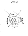
- Fig. 2 shows a control grip portion 1 of the operation switch, which has an oval shape viewed from the front.
- the user can grasp the whole grip portion by the palm of his/her hand and move the grip portion in a longitudinal direction X and in a vertical direction Y and rotate the grip portion in a forward/backward direction ⁇ .
- the switches for reclining movement A, the switch for back-portion tilting movement B and the switch 3 for front-portion tilting movement D are designed each to automatically return to its normal neutral position where no operation is made.
Description
- The present invention relates to an operation switch for a power seat in a vehicle, which is used for moving forward/backward, tilting the seat and adjusting the level of the front/back portion of the seat.
-
EP 0 530 509 A2 andDE 197 29 866 A1 each disclose an operation switch of a power seat in a vehicle, which is formed as an operation switch box provided with a seat reclining switch, seat switches for sliding the seat forward and backward and switches for adjusting the height of the front and rear portion of the seat. This operation switch box is easy to mount but requires the occupant to separately operate each of the switches arranged on the case. Namely, the occupant has to felt for a necessary one of the respective function switches on the switch box and operates it by his or her finger. This operation switch box is not easy to operate and cause incorrect selection of switches. -
DE 100 02 493 C1 on which the preamble ofclaim 1 is based shows another power seat operation switch which is featured by improved operability and which comprises a round control grip attached to the side of the power seat which is similar to the embodiment as shown inFig. 7 . Thisgrip 71 allows the occupant to slide the seat forward or backward by moving the grip in the direction X and recline the back of the seat by rotating thegrip 71 in the direction θ. Thisgrip 71 is also provided at its top surface with aseesaw type switch 72 for adjusting the level of the front portion of the seat up or down by pressing an upper part or a lower part of the switch and aseesaw switch 73 for adjusting the level of the back portion of the seat up or down by pressing an upper part or a lower part of the switch. This operation switch device allows the occupant to adjust the power seat by operating the control grip in conformity with the movement of the seat. - The above-described power seat switch attached to the side of the power seat in the vehicle allows the occupant to adjust the power seat by moving the control grip in accordance with the movement of the power seat in such a manner that the seat is moved forward and backward by moving the grip forward and backward and the back of the seat is tilted forward and backward by turning the grip to forward and backward. However, the occupant being in the state holding the grip cannot operate the seesaw type switches for adjusting the level of the seat.
- The above problems are.overcome by an operation switch for a power seat in a vehicle, comprising a main body attached to a side of the power seat, said body being provided thereat with a control grip portion operable to move in a longitudinal direction and a vertical direction relative to the main body and turn forward and backward about a center axis of the main body, wherein the main body incorporates a switch for sliding the power seat forward or backward while moving the grip portion in the longitudinal direction, a switch for reclining a backrest of the seat while turning the grip portion forward or backward, and a switch for tilting the rear part of the seat up or down while moving the grip portion in the vertical direction, characterized in that said control grip portion incorporates in the front part thereof a switch for tilting the front part of the seat up or down while operating upward or downward a knob attached to a front of the grip portion.
- The power seat operation switch according to the present invention allows a user to adjust the power seat forward/backward and up/down and reclined to suit the occupant by naturally operating by hand only a grip portion of the operation switch, feeling the high operability of the switch in conformity with movements of the power seat.
-
-
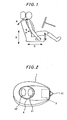
Figure 1 is illustrative of the operation of a power seat by using a power seat operation switch according to the present invention. -
Figure 2 is a front view of a control grip portion of a power seat operation switch for a vehicle according to the present invention. -
Figure 3 is a front view of a control grip portion of a power seat operation switch according to the present invention, which is in the palm of a user's hand for operating the power seat. -
Figure 4 is side sectional view of a main body of a power seat operating switch incorporating a switch for tilting a back of the seat and a switch for sliding the seat. -
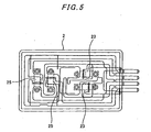
Figure 5 is a plan view of contact portions of the switch structure shown inFig. 4 . -
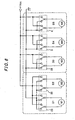
Figure 6 shows driving circuits of driving motors to be operated by corresponding switches of a power seat operation switch according to the present invention. -
Figure 7 is a front view of a control grip portion of a conventional operation switch for a power seat for a vehicle. -
Fig. 1 illustrates movements of a power seat which is operated by using an operation switch according to the present invention. The power seat can be adjusted by using the power operation switch capable of reclining the seat backrest as shown by arrows A, adjusting the seat back portion up and down as shown by arrows B, sliding the seat body forward and backward as shown by arrows C, moving the seat front portion up and down as shown by arrows D and push/draw the seat lumbar support forward/backward as shown by arrows E. Conventional driving mechanisms may be applied for respective movements of the power seat are therefore not shown. - A power seat operation switch according to the present invention has a main body mounted on one side of the power seat and a control grip portion attached to the main body. The control grip portion of the power seat operation switch can be operated in directions forward/backward and upward/downward relative and also turned forward/backward relative to the main body attached to the seat.
-
Fig. 2 shows acontrol grip portion 1 of the operation switch, which has an oval shape viewed from the front. As shown inFig. 3 , the user can grasp the whole grip portion by the palm of his/her hand and move the grip portion in a longitudinal direction X and in a vertical direction Y and rotate the grip portion in a forward/backward direction θ. -
Fig. 4 shows the structure of thepower switch body 2 which comprises a switch for rear-portion tilting movement B to raise and lower the rear portion of the seat, a switch for slide movement C to slide the seat forward and backward.Fig. 5 shows contacts of the switches shown inFig. 4 . - Referring to
Fig. 4 , the fore-and-aft movement of the control grip portion (not shown) mounted on thelever 21 of the operation switch body causes thelever 21 to move and switch on and off pairedseesaw type switches 23 through acontactor 22, changing the direction of rotation of a driving motor for sliding the seat. - The up-and-down movement of the control grip portion causes the
lever 21 to move and switch on and off pairedseesaw type switches 25 throughcontactor 24, changing the direction of rotation of a driving motor for moving the rear portion of the seat. - Similarly, the forward-and-backward rotational movement of the control grip portion causes a lever (not shown) attached thereto to move and switch on and off paired seesaw type switches, changing the direction of rotation of a driving motor for reclining the seat. This conventional switch structure is also incorporated in the main body of the power seat operating switch.
- Referring back to
Fig. 2 , thecontrol grip portion 1 of the power seat switch incorporates a switch 3 for front portion tilting movement, which operates to raise or lower the front portion of the seat when the user moves up or down aknob 31 of thegrip portion 1. - The switches for reclining movement A, the switch for back-portion tilting movement B and the switch 3 for front-portion tilting movement D are designed each to automatically return to its normal neutral position where no operation is made.
- In the central part of the
grip portion 1, a pair of seesaw type push-button switches 4 is mounted, which has twopush buttons - In
Fig. 6 , there is shown a drive circuit D1 for normally or reversely rotating a motor M1 for sliding the power seat forward or backward in accordance with switching action of pairedseesaw type switches 23 in themain body 2 of the power seat operation switch when the control grip portion is operated for the sliding operation C; a drive circuit D2 for normally or reversely rotating a motor M2 for tilting up or down the rear portion of the power seat in accordance with switching action of pairedseesaw type switches 25 in themain body 2 of the power seat operation switch when the control grip portion is operated for the rear-portion tilt operation B; a drive circuit D3 for normally or reversely rotating a motor M3 for reclining the backrest of the power seat in accordance with switching action of pairedseesaw type switches 26 in themain body 2 of the power seat operation switch when the control grip portion is operated for the reclining operation A; a drive circuit D4 for normally or reversely rotating a motor M4 for tilting up or down the front portion of the power seat in accordance with switching action of a switch 3 when the control grip portion of the operation switch is operated for the front-portion tilting operation D; and a drive circuit D5 for normally or reversely rotating a motor M5 for pushing or drawing the lumber support of the power seat in accordance with switching action of pairedbutton switches 4 of the control grip portion when it is operated for the lumbar support operation E. - In the power seat operation switch for vehicle according to the present invention, the
control grip portion 1 may not necessarily be provided at its center part with a pair of push-button switches 4 for adjusting the lumber support. - As is apparent from the foregoing, the power seat operation switch according to the present invention is devised to allow a user to adjust the power seat forward/backward and up/down and reclined to suit the user by naturally operating by hand only a grip portion of the operation switch, feeling the high operability of the switch in conformity with movements of the power seat.
- An operation switch for a power seat in vehicle, which allows an occupant to adjust the seat forward/backward, tilt the rear/front part of the seat up/down and recline a backrest of the seat by naturally operating a grip portion and which comprises a main body attached to a side of the seat and a grip portion movable in longitudinal and vertical directions relative to the main body and turnable forward/backward about a center axis of the body, wherein the main body incorporates a switch for sliding the power seat forward or backward while moving the grip portion in the longitudinal direction, a switch for tilting the rear part of the seat up or down while moving the grip portion in the vertical direction, a switch for reclining a backrest of the seat while turning the grip portion forward or backward and a switch for tilting the front part of the seat up or down while operating upward or downward a knob attached to a front of the grip portion.
Claims (2)
- An operation switch for a power seat in a vehicle, comprising a main body (2) attachable to a side of the power seat, said body (2) being provided thereat with a control grip portion (1) operable to move in a longitudinal direction (X) and a vertical direction (Y) relative to the main body (2) and turn forward and backward (θ) about a center axis of the main body (2),
wherein the main body (2) incorporates a switch (23) for sliding (C) the power seat forward or backward while moving the grip portion (1) in the longitudinal direction (X), a switch (26) for reclining (A) a backrest of the seat while turning (θ) the grip portion forward or backward, and,
a switch (25) for tilting (B) the rear part of the seat up or down while moving the grip portion in the vertical direction (Y),
characterized in that said control grip portion (1) incorporates in the front part thereof a switch (3) for tilting (D) the front part of the seat up or down while operating upward or downward a knob (31) attached to a front of the grip portion (1). - An operating switch for a power seat in a vehicle as defined in claim 1, characterized in that the control grip portion (1) of the power seat switch has a pair of pushbutton switches (41, 42) arranged at a center part of the grip portion (1) along the longitudinal axis thereof for pushing forward (E) a lumbar support of the power seat while pressing a front one (41) of the paired switches and draw-in the lumbar support while pressing a rear one (42) of the paired switches.
Applications Claiming Priority (1)
| Application Number | Priority Date | Filing Date | Title |
|---|---|---|---|
| JP2005160368A JP4560817B2 (en) | 2005-04-28 | 2005-04-28 | Operation switch for vehicle power seat |
Publications (3)
| Publication Number | Publication Date |
|---|---|
| EP1717094A2 EP1717094A2 (en) | 2006-11-02 |
| EP1717094A3 EP1717094A3 (en) | 2007-06-13 |
| EP1717094B1 true EP1717094B1 (en) | 2008-09-03 |
Family
ID=36659928
Family Applications (1)
| Application Number | Title | Priority Date | Filing Date |
|---|---|---|---|
| EP06005905A Active EP1717094B1 (en) | 2005-04-28 | 2006-03-22 | Power seat operation switch |
Country Status (5)
| Country | Link |
|---|---|
| US (1) | US20060243566A1 (en) |
| EP (1) | EP1717094B1 (en) |
| JP (1) | JP4560817B2 (en) |
| CN (1) | CN100411917C (en) |
| DE (1) | DE602006002540D1 (en) |
Families Citing this family (14)
| Publication number | Priority date | Publication date | Assignee | Title |
|---|---|---|---|---|
| US20070267243A1 (en) * | 2006-05-19 | 2007-11-22 | Textron Inc. | Multi-purpose key switch for lightweight utility vehicle |
| JP4917416B2 (en) * | 2006-11-29 | 2012-04-18 | トヨタ紡織株式会社 | Electric operating device for vehicle seat |
| JP5386189B2 (en) | 2009-02-05 | 2014-01-15 | デルタ工業株式会社 | Power seat adjustment device |
| US8471158B2 (en) * | 2009-12-17 | 2013-06-25 | Omron Dualtec Automotive Electronics Inc. | Power seat switch assembly |
| JP5605907B2 (en) * | 2011-01-11 | 2014-10-15 | アルプス電気株式会社 | Switch device |
| IN2015DN01655A (en) | 2012-08-31 | 2015-07-03 | Nhk Spring Co Ltd | |
| US9783081B2 (en) * | 2013-06-26 | 2017-10-10 | Ricon Corp. | Power transfer seat |
| US11124092B2 (en) | 2013-06-26 | 2021-09-21 | Ricon Corp. | Transfer seat and method |
| CN103692935B (en) * | 2013-11-26 | 2016-04-06 | 上海延锋江森座椅有限公司 | A kind of automotive seat regulating handle |
| USD762180S1 (en) * | 2013-12-20 | 2016-07-26 | Ford Motor Company | Vehicle switch |
| CN104085322A (en) * | 2014-06-20 | 2014-10-08 | 苏州中航中振汽车饰件有限公司 | Automobile seat provided with table board |
| CN104085319A (en) * | 2014-06-20 | 2014-10-08 | 苏州中航中振汽车饰件有限公司 | Automobile seat provided with fixed armrests |
| WO2017064534A1 (en) * | 2015-10-14 | 2017-04-20 | Continental Automotive Gmbh | Seat adjustment control using wearable |
| DE102018117000B4 (en) * | 2018-07-13 | 2020-04-02 | Grammer Ag | Vehicle seat with control device |
Family Cites Families (15)
| Publication number | Priority date | Publication date | Assignee | Title |
|---|---|---|---|---|
| US4678872A (en) * | 1986-09-10 | 1987-07-07 | United Techologies Automotive, Inc. | Button set and switch |
| JPH0340124U (en) * | 1988-12-01 | 1991-04-17 | ||
| DE3933561C1 (en) * | 1989-10-07 | 1991-01-31 | Mercedes-Benz Aktiengesellschaft, 7000 Stuttgart, De | |
| JPH0410940U (en) * | 1990-05-14 | 1992-01-29 | ||
| EP0530509B1 (en) * | 1991-07-31 | 1996-06-19 | Omron Corporation | Switch device |
| JPH0629111A (en) | 1992-07-10 | 1994-02-04 | Murata Mfg Co Ltd | Method of adjusting resistance value of resistor |
| JPH0922642A (en) * | 1995-07-07 | 1997-01-21 | Yazaki Corp | Multidirectional changeover switch |
| JPH09240340A (en) | 1996-03-01 | 1997-09-16 | Niles Parts Co Ltd | Power seat switch |
| US5866862A (en) * | 1997-04-07 | 1999-02-02 | Ut Automotive Dearborn, Inc. | Vehicle positioning control |
| DE19729866B4 (en) * | 1997-07-11 | 2006-06-14 | Bayerische Motoren Werke Ag | Switch arrangement for an externally adjustable vehicle seat |
| DE10002493C1 (en) * | 2000-01-21 | 2001-06-13 | Faure Bertrand Sitztech Gmbh | Automobile passenger seat adjustment switch has single switch operating element rotated in opposite directions and provided with horizontal and vertical sliding and tipping movements |
| ES2160540B1 (en) * | 2000-02-11 | 2003-04-01 | Lear Automotive Eeds Spain | MEMBRANE SLIDING SWITCH. |
| CN2433118Y (en) * | 2000-05-30 | 2001-06-06 | 朱丰 | Seat of electric vehicle |
| ITTO20020165A1 (en) * | 2002-02-27 | 2003-08-27 | Bitron Spa | MANUAL CONTROL FOR ADJUSTING THE POSITION OF A SEAT. |
| FR2847712B1 (en) * | 2002-11-22 | 2008-08-22 | Dav | METHOD FOR CONTROLLING AT LEAST TWO FUNCTIONS OF AN ORGAN AND / OR AT LEAST TWO DISTINCT PARTS OF AN ORGAN AND CONTROL DEVICE |
-
2005
- 2005-04-28 JP JP2005160368A patent/JP4560817B2/en active Active
-
2006
- 2006-03-22 EP EP06005905A patent/EP1717094B1/en active Active
- 2006-03-22 DE DE602006002540T patent/DE602006002540D1/de active Active
- 2006-04-13 CN CNB2006100736364A patent/CN100411917C/en active Active
- 2006-04-21 US US11/409,413 patent/US20060243566A1/en not_active Abandoned
Also Published As
| Publication number | Publication date |
|---|---|
| CN1853985A (en) | 2006-11-01 |
| DE602006002540D1 (en) | 2008-10-16 |
| CN100411917C (en) | 2008-08-20 |
| JP4560817B2 (en) | 2010-10-13 |
| EP1717094A2 (en) | 2006-11-02 |
| JP2006310243A (en) | 2006-11-09 |
| US20060243566A1 (en) | 2006-11-02 |
| EP1717094A3 (en) | 2007-06-13 |
Similar Documents
| Publication | Publication Date | Title |
|---|---|---|
| EP1717094B1 (en) | Power seat operation switch | |
| JP5386189B2 (en) | Power seat adjustment device | |
| EP2266833B1 (en) | Interface for vehicle function control via touch screen | |
| JPH0755636B2 (en) | Control device for controlling an operating motor for adjusting a car seat | |
| US6894234B1 (en) | Seat adjusting mechanism | |
| JP2007522016A (en) | Operation device for vehicle | |
| WO2007086466A1 (en) | Seat | |
| JP2004504983A (en) | Arrangement of operator control | |
| CN110281859A (en) | Control operator's control unit of the electronic adjustable lumbar support part of automobile seat | |
| JP2002144937A (en) | Automobile power seat switch device | |
| CN110712578A (en) | Vehicle seat with operating device | |
| CN110712577B (en) | Vehicle seat with operating device | |
| US20080012413A1 (en) | Seat Adjustment Mechanism Comprising a Rotative Actuating Element | |
| CN109476233B (en) | Operating device for a motor vehicle and method for operating a motor vehicle by means of an operating device | |
| CN109982893B (en) | Seat for a vehicle having a segmented backrest and a movable lumbar | |
| JPH11208385A (en) | Arm rest setting switch for vehicle | |
| JP2001084873A (en) | Switch device | |
| US20040108192A1 (en) | Electromotive furniture drive for displacing parts of a piece of furniture in relation to each other | |
| EP0545676A1 (en) | An ergonomic control system for swing reach vehicles | |
| KR100692076B1 (en) | A contact on the power seat switch | |
| JP2943095B2 (en) | Control stick for reach forklift truck | |
| JP2000118275A (en) | Vehicular seat | |
| US11623546B2 (en) | Seat switch device | |
| JPH08268125A (en) | Control device for vehicular seat | |
| CN220856399U (en) | Electric eight-direction function regulating switch structure |
Legal Events
| Date | Code | Title | Description |
|---|---|---|---|
| PUAI | Public reference made under article 153(3) epc to a published international application that has entered the european phase |
Free format text: ORIGINAL CODE: 0009012 |
|
| 17P | Request for examination filed |
Effective date: 20060322 |
|
| AK | Designated contracting states |
Kind code of ref document: A2 Designated state(s): AT BE BG CH CY CZ DE DK EE ES FI FR GB GR HU IE IS IT LI LT LU LV MC NL PL PT RO SE SI SK TR |
|
| AX | Request for extension of the european patent |
Extension state: AL BA HR MK YU |
|
| PUAL | Search report despatched |
Free format text: ORIGINAL CODE: 0009013 |
|
| AK | Designated contracting states |
Kind code of ref document: A3 Designated state(s): AT BE BG CH CY CZ DE DK EE ES FI FR GB GR HU IE IS IT LI LT LU LV MC NL PL PT RO SE SI SK TR |
|
| AX | Request for extension of the european patent |
Extension state: AL BA HR MK YU |
|
| 17Q | First examination report despatched |
Effective date: 20071115 |
|
| AKX | Designation fees paid |
Designated state(s): DE FR GB IT |
|
| GRAP | Despatch of communication of intention to grant a patent |
Free format text: ORIGINAL CODE: EPIDOSNIGR1 |
|
| GRAS | Grant fee paid |
Free format text: ORIGINAL CODE: EPIDOSNIGR3 |
|
| GRAA | (expected) grant |
Free format text: ORIGINAL CODE: 0009210 |
|
| AK | Designated contracting states |
Kind code of ref document: B1 Designated state(s): DE FR GB IT |
|
| REG | Reference to a national code |
Ref country code: GB Ref legal event code: FG4D |
|
| REF | Corresponds to: |
Ref document number: 602006002540 Country of ref document: DE Date of ref document: 20081016 Kind code of ref document: P |
|
| PLBE | No opposition filed within time limit |
Free format text: ORIGINAL CODE: 0009261 |
|
| STAA | Information on the status of an ep patent application or granted ep patent |
Free format text: STATUS: NO OPPOSITION FILED WITHIN TIME LIMIT |
|
| 26N | No opposition filed |
Effective date: 20090604 |
|
| REG | Reference to a national code |
Ref country code: FR Ref legal event code: PLFP Year of fee payment: 11 |
|
| REG | Reference to a national code |
Ref country code: FR Ref legal event code: PLFP Year of fee payment: 12 |
|
| REG | Reference to a national code |
Ref country code: FR Ref legal event code: PLFP Year of fee payment: 13 |
|
| PGFP | Annual fee paid to national office [announced via postgrant information from national office to epo] |
Ref country code: FR Payment date: 20230208 Year of fee payment: 18 |
|
| PGFP | Annual fee paid to national office [announced via postgrant information from national office to epo] |
Ref country code: IT Payment date: 20230213 Year of fee payment: 18 Ref country code: GB Payment date: 20230202 Year of fee payment: 18 Ref country code: DE Payment date: 20230131 Year of fee payment: 18 |