EP1716683B1 - Frequency compensated communications reception - Google Patents
Frequency compensated communications reception Download PDFInfo
- Publication number
- EP1716683B1 EP1716683B1 EP05708328A EP05708328A EP1716683B1 EP 1716683 B1 EP1716683 B1 EP 1716683B1 EP 05708328 A EP05708328 A EP 05708328A EP 05708328 A EP05708328 A EP 05708328A EP 1716683 B1 EP1716683 B1 EP 1716683B1
- Authority
- EP
- European Patent Office
- Prior art keywords
- matrix
- vector
- cost function
- received signal
- signal
- Prior art date
- Legal status (The legal status is an assumption and is not a legal conclusion. Google has not performed a legal analysis and makes no representation as to the accuracy of the status listed.)
- Expired - Lifetime
Links
- 238000004891 communication Methods 0.000 title claims abstract description 18
- 230000006870 function Effects 0.000 claims abstract description 126
- 239000011159 matrix material Substances 0.000 claims abstract description 115
- 239000013598 vector Substances 0.000 claims abstract description 101
- 238000012549 training Methods 0.000 claims abstract description 93
- 230000003044 adaptive effect Effects 0.000 claims abstract description 48
- 238000000034 method Methods 0.000 claims description 61
- 238000012545 processing Methods 0.000 claims description 9
- 238000001514 detection method Methods 0.000 description 44
- 239000000523 sample Substances 0.000 description 23
- 238000013459 approach Methods 0.000 description 10
- 230000008859 change Effects 0.000 description 9
- 230000000694 effects Effects 0.000 description 8
- 230000002596 correlated effect Effects 0.000 description 6
- 230000005540 biological transmission Effects 0.000 description 5
- 230000001934 delay Effects 0.000 description 5
- 238000011084 recovery Methods 0.000 description 5
- 230000007480 spreading Effects 0.000 description 5
- 238000004364 calculation method Methods 0.000 description 4
- 238000001914 filtration Methods 0.000 description 4
- 230000033001 locomotion Effects 0.000 description 4
- 238000004088 simulation Methods 0.000 description 4
- 230000015572 biosynthetic process Effects 0.000 description 3
- 238000004422 calculation algorithm Methods 0.000 description 3
- 238000004590 computer program Methods 0.000 description 3
- 230000001143 conditioned effect Effects 0.000 description 3
- 238000012937 correction Methods 0.000 description 3
- 230000008520 organization Effects 0.000 description 3
- 230000000737 periodic effect Effects 0.000 description 3
- 238000001228 spectrum Methods 0.000 description 3
- 238000003786 synthesis reaction Methods 0.000 description 3
- 238000007792 addition Methods 0.000 description 2
- 238000005284 basis set Methods 0.000 description 2
- 238000000354 decomposition reaction Methods 0.000 description 2
- 238000002156 mixing Methods 0.000 description 2
- 238000010295 mobile communication Methods 0.000 description 2
- 230000003287 optical effect Effects 0.000 description 2
- 230000010363 phase shift Effects 0.000 description 2
- 230000008569 process Effects 0.000 description 2
- 238000012360 testing method Methods 0.000 description 2
- 238000007476 Maximum Likelihood Methods 0.000 description 1
- 239000008186 active pharmaceutical agent Substances 0.000 description 1
- 230000008901 benefit Effects 0.000 description 1
- 239000002131 composite material Substances 0.000 description 1
- 238000010276 construction Methods 0.000 description 1
- 230000001276 controlling effect Effects 0.000 description 1
- 238000005314 correlation function Methods 0.000 description 1
- 230000000875 corresponding effect Effects 0.000 description 1
- 230000007423 decrease Effects 0.000 description 1
- 230000003247 decreasing effect Effects 0.000 description 1
- 230000002950 deficient Effects 0.000 description 1
- 230000003111 delayed effect Effects 0.000 description 1
- 238000012217 deletion Methods 0.000 description 1
- 230000037430 deletion Effects 0.000 description 1
- 230000003467 diminishing effect Effects 0.000 description 1
- 238000002474 experimental method Methods 0.000 description 1
- 238000010348 incorporation Methods 0.000 description 1
- 230000004044 response Effects 0.000 description 1
- 238000012776 robust process Methods 0.000 description 1
- 238000005070 sampling Methods 0.000 description 1
- 238000010561 standard procedure Methods 0.000 description 1
- 230000003068 static effect Effects 0.000 description 1
- 230000007704 transition Effects 0.000 description 1
- 238000012800 visualization Methods 0.000 description 1
Images


Classifications
-
- H—ELECTRICITY
- H04—ELECTRIC COMMUNICATION TECHNIQUE
- H04L—TRANSMISSION OF DIGITAL INFORMATION, e.g. TELEGRAPHIC COMMUNICATION
- H04L27/00—Modulated-carrier systems
- H04L27/0014—Carrier regulation
Definitions
- This invention relates to frequency compensated communications reception, and more particularly to a method, an apparatus and a computer program for such reception.
- any radio communications receiver must first acquire a signal of interest. In practice this can give difficulty associated with conventional superheterodyne techniques: i.e. a transmitter upconverts the frequency of a signal for transmission to radio frequency (RF) by mixing it with a high frequency local oscillator (LO) signal. A receiver downconverts a received signal to baseband by mixing it with an LO signal.
- RF radio frequency
- LO local oscillator
- the transmit and receive LOs may not be accurately at the same frequency and if so will not cancel out exactly, so the baseband signal will have a residual frequency offset which may make it difficult or even impossible for a receiver to acquire the wanted signal.
- the frequency offset arising from signal propagation through the atmosphere and relative motion between transmitter and receiver. There may also be interference and noise.
- a training sequence in it, i.e. a sequence of prearranged data known to the intended receiver: see for example the Standardization Agreement, North Atlantic Treaty Organization, Military Agency for Standardization, "Characteristics of 1200/2400/3600 bits per second single tone modulators/demodulators for HF radio links", 1989.
- Digital communications signals are transmitted as blocks of data known as "frames", in which the training sequence is in a prearranged position normally at the beginning of the frame.
- the receiver correlates the training sequence with the received signal, and if a high correlation is reached the training sequence has been located in the received signal. The receiver can then declare that detection has occurred. It is necessary for correlation to be carried out at a frequency sufficiently close to the actual frequency of the received signal such that the magnitude of the correlation is within 1dB or so of the optimum.
- the actual frequency offset of a received signal may be unknown, albeit a frequency uncertainty range ⁇ F may be known in which the signal may lie. This implies that during signal acquisition a search over the known frequency range is needed.
- the simplest approach is to use a set of trial frequency offsets in the known frequency range, the frequencies being sufficiently close together that the correlation loss for a received signal frequency between two adjacent trial frequencies is in the region of, or preferably less than, 1 dB.
- a detection parameter or statistic is calculated for each frequency offset indicating the degree of correlation obtained between the training sequence and the signal with that offset.
- the offset associated with the maximum degree of correlation is then taken to be the actual signal offset.
- the problem here is that a large set of trial frequency offsets may be needed, which requires a burdensome degree of computation to calculate detection parameters.
- 'chip' is a term of art in the field of DS-SS communications.
- data bits of a signal at a rate R b are multiplied by elements of a spreading code whose values change at a rate R c where R c >R b .
- the elements of the spreading code are called 'chips' and the rate of change R c is called the chip rate.
- R c is a convenient term defined in the art of communications.
- Another convenient term defined in the art of communications is "normalised Doppler", which is a product f d T or f d T c of Doppler offset f d and symbol time interval T or chip time interval T c .
- a military HF M-ary phase-shift-keying (MPSK) communications system should have, typically,
- the degree of correlation obtained between a training sequence and a signal with Doppler offset f d is proportional to
- Signal acquisition may be implemented with a receiver having a single antenna or multiple antenna elements.
- To perform signal acquisition in the presence of interference and noise with a receiver having multiple antenna elements it is known to use all of the antenna elements jointly.
- One method is a least-squares approach as disclosed by Brennan L.E. and Reed I.S., in "An Adaptive Array Signal Processing Algorithm for Communications", IEEE Trans. On Aerospace and Electronic Systems, Vol. AES-18, No. 1, Jan 1982, pp124-30 .
- M antenna elements are used to acquire a signal with a training sequence having L symbols each extending over a time interval of duration T.
- the training sequence is expressed as a (K,1) vector. c, with K>M.
- the output signal samples are assembled to provide a (K,M) data matrix X at time nT s .
- n is a time index number that indicates the time associated with the last matrix row in X .
- w is an (M,1) weight vector with M vector elements which weight outputs of respective antenna elements, and the weighted outputs are summed to combine them before subtracting the training sequence vector. c as indicated in Equation (1).
- the weight vector w is therefore a beamformer weight because it implements a weighted combination of antenna outputs as is done in forming a beam to or from a phased array of antenna elements. It is known from L.E Brennan and L.S. Reed, "An Adaptive Array Signal Processing Algorithm for Communications", IEEE Transactions Aerospace Electronics Systems, Vol. 18, No.
- US 6393073 is similarly concerned with a system having multiple antennae. It devises weighting coefficients for specific components of the composite signals received by the multiple antennae and selects the best weighting coefficients using a training sequence and a least square algorithm.
- the present invention provides an automated method for compensating for frequency offset in a received signal and approximating a desired frequency-shifted signal comprising the steps of constructing a reference signal that is an adaptively formed combination of basis functions and an original training sequence; minimising a cost function of the reference signal, where the cost function includes an adaptively weighted combination of the basis functions, the original training sequence and the received signal; and acquiring the desired frequency-shifted signal when the cost function indicates that there is an acceptable degree of correlation between the constructed reference signal and the received signal.
- the invention provides the advantage that the adaptive combination automatically compensates for frequency offset within a range covered by the basis functions without the need to determine offset explicitly.
- the method of the invention may include constructing a reference signal or comparison training sequence that is an adaptively formed combination of basis functions and the training sequence. It may be for acquiring a signal with a receiver having multiple antenna elements, and may include constructing the reference signal by minimising a cost function constructed from an adaptively weighted combination of basis functions, a training sequence and a received signal, together with a constraint to obtain non-trivial solutions. The constraint may require non-zero signal power.
- the adaptive weight vectors w and v may be determined at intervals from true estimates of a correlation matrix determined from multiple data vectors and from inverses of such estimates recursively updated to reflect successive new data vectors which are rows of the matrix X.
- the inverse correlation matrices may be recursively updated by:
- the method may include acquiring a signal with a receiver having a single antenna element and constructing the reference signal by minimising a cost function constructed from an adaptively weighted combination of basis functions, a training sequence, a scaled received signal and a constraint requiring non-zero signal power.
- J ⁇ x-Gv ⁇ 2 + ⁇ ( ⁇ *x H x ⁇ - 1)
- ⁇ a scaling factor
- x a vector of received signal samples
- G a matrix equal to CF
- v ⁇ , C, F and H are as defined earlier.
- the present invention provides apparatus for frequency compensated communications reception comprising: means for compensating for frequency offset in a received signal and approximating to a desired frequency-shifted signal to be acquired; means for constructing a reference signal that is an adaptively formed combination of basis functions and an original training sequence; wherein the means for constructing the reference signal is operable to minimise a cost function, the cost function including an adaptively weighted combination of basis functions, the original training sequence and the received signal; and means for acquiring the desired frequency-shifted signal when the cost function indicates that there is an acceptable degree of correlation between the constructed reference signal and the received signal.
- the present invention provides computer software for controlling a computer processor and for use in frequency compensated communications reception characterised in that it includes program code instructions for compensating for frequency offset in a received signal and approximating to a desired frequency-shifted signal comprising: program code instructions for constructing a reference signal that is an adaptively formed combination of basis functions and an original training sequence; program code instructions for minimising a cost function of the reference signal, where the cost function includes an adaptively weighted combination of the basis functions, the original training sequence and the received signal; and program code instructions for acquiring the desired frequency-shifted signal when the cost function indicates that there is an acceptable degree of correlation between the constructed reference signal and the received signal.
- the apparatus and software aspects of the invention may have preferred features equivalent mutatis mutandis to those of the method aspect.
- a reference signal/training sequence is constructed that is an approximation to a reference signal/training sequence in a received signal. This is achieved by multiplication of an original reference signal/training sequence by an adaptive combination of an appropriately selected set of basis functions that span a subspace in which the cisoid (complex sinusoid) associated with the frequency offset lies.
- the basis functions may for example be complex sinusoids (cisoids), real sinusoids, functions derived from a singular value decomposition (SVD) of a set of cisoids or sinusoids spanning a Doppler offset range, Legendre polynomials or prolate spheroids. All of these have been used and found to be effective.
- a constructed reference signal/training sequence a product of the original training sequence and a weighted combination of basis functions
- the degree of correlation between the two is determined using a cost function in this example.
- a minimum in the cost function indicates a maximum correlation and a most appropriately weighted combination of basis functions.
- the product Fv provides a weighted combination of the basis functions in F.
- the parameter ⁇ is a Lagrange multiplier and the term of which it is a part constrains beamformer output power to be non-zero, in order to obtain non-trivial solutions for w and v. Other constraints may also be used. Constraining the beamformer output power is a simple scaling operation which has no impact on signal acquisition. As described by S.Haykin, Adaptive Filter Theory, 2 nd ed. Pub. Prentice-Hall, Englewood Cliffs, NJ, 1991, J has conjugate derivatives with respect to v and w denoted by ⁇ J v* and ⁇ J w* respectively. Here * indicates a complex conjugate.
- Equation (6) is an eigenvalue equation, solution of which gives the weight vector w.
- w is taken as a principal eigenvector associated with a maximum eigenvalue of A (this corresponds to scaling and does not affect results because w is a beamformer weight).
- the vector v can then be found by substituting for w in Equation (4).
- a detection statistic is now defined to provide a measure of the degree of success of signal acquisition.
- the frequency compensation method of the invention synthesises a version of the training sequence which matches the frequency offset equivalent in the received signal. This allows the signal to be acquired/detected, but it leaves unaffected the received signal frequency offset, i.e. that between the received signal and the receiver LO together with any contribution from signal propagation effects. Consequently, this frequency offset remains to be removed from the array output before the data in the signal can be obtained.
- a correlation of the complex conjugate transpose g H of g with cisoid frequencies f that span the frequency uncertainty region is therefore performed to determine which frequency f opt is a best match to the frequency offset between the received signal and the receiver LO; i.e. a frequency f opt and associated cisoid s (f opt )are found which maximise a correlation expression
- C is a diagonal matrix
- G is a diagonal matrix whose diagonal elements are elements of g , which itself is a weighted version of the basis functions.
- s*(f opt ) is the cisoid required to remove the frequency offset from the beamformer output Xw over the training sequence portion of a data frame: this cisoid is now extended to cover the full duration of the data frame, which gives e -j ⁇ (diag(s*(f opt ))) Xw as a recovered signal from which frequency offset has been removed at least in large part.
- the superscript T denotes vector transpose.
- Xw is the beamformer output over the training sequence portion of the data frame and C is a diagonal matrix with training sequence elements as defined previously.
- the recovered signal is e -j ⁇ (diag(s* (f opt ))) Xw .
- frequency searching can be divided into regions with decreasing step size, e.g. a bisection search can be performed in steps of say 10, 5, 1, 0.1Hz; a frequency offset is first localised to one 10Hz interval, then it is localised to one of two 5Hz intervals and so on until it is localised to one 0.1 Hz interval.
- the k th element in g i.e.
- the frequency offset can also be estimated in other ways (i.e. conventional single-channel methods) based on optimum T-spaced samples. In this connection see e.g. Meyr H. Moeneclaey M. and Fmül S.A., Digital Communications Receivers, pub. John Wiley and Sons, New York, 1988 , and Su Y.T. and Wu R.C., "Frequency Acquisition and Tracking in High Dynamic Environments", IEEE Trans. Vehic. Technol., Vol. 49, No. 6, Nov 2000, pp2419-29 .
- a Doppler shift estimated from the training data can be applied to the data segment of the data frame (assumed to consist of a training sequence followed by a data block).
- the objective is to find a matrix F consisting of a suitable set of functions that allows synthesis of a cisoid that lies within a given range of frequencies.
- the frequency range may be divided into, say, a number of sub-ranges.
- a suitable set of functions spanning a given range of frequencies is obtained as follows. It is firstly assumed that the required frequency offset does not exceed a maximum value that is known in advance.
- a matrix A is then formed with columns which are respective complex sinusoids (i.e. cisoids) in other words elements in each of its columns are values defining these cisoids.
- This SVD is now computed as described in the Haykin reference previously given. Since the matrix A is composed of cisoids some of which will be correlated with one another, it is likely to be rank deficient, i.e. to have a rank r (denoting the number of its linearly independent columns) which is less than the number of columns of A.
- the rank r can be found via information theoretic techniques in the Haykin reference or by thresholding singular values resulting from the SVD of the matrix A.
- the basis function set is optimised in the sense that it should minimise mean-square-error in re-construction of a cisoid.
- the initial detection or acquisition search may be modified to cover a range of time delays. There are two reasons why time delays are relevant: the training sequence in a block of received data has a starting point which is initially unknown, so the acquisition search may be speeded up searching in parallel for the starting point, i.e. at a number of different delays simultaneously. Alternatively, it might be useful to combine multipath signals, these being signals which are relatively delayed versions of one another.
- ⁇ a matrix of matrices C 1 F etc.
- v ⁇ a vector of vectors v 1 etc.
- the n th matrix C n has n-1 zeroes on the upper part of its diagonal, the rest of which is occupied by at least the initial part of the training sequence. Solutions of Equation (7) for the weight vectors w and v ⁇ can be found as indicated earlier.
- Adaptive frequency compensation in accordance with the invention was tested by simulation.
- a received signal was simulated as an HF Standard NATO Agreement 4285 signal with signal to noise ratio 3 dB: this signal was incident on an antenna array with six antenna elements arranged with centres in a straight line spaced by half-wavelength intervals.
- the signal had a channel symbol rate of 2.4 kilosymbols/s.
- This signal was based on a periodic data frame structure of 256 symbols the first 80 of which form a known training sequence published in the Standardization Agreement, North Atlantic Treaty Organization, Military Agency for Standardization, "Characteristics of 1200/2400/3600 bits per second single tone modulators/demodulators for HF radio links", 1989 (referred to as "STANAG").
- the angle of incidence of the signal on the antenna array was 30° from the normal to the antenna array.
- a barrage noise jammer with jammer to noise ratio 30 dB incident from 50° from the normal to the antenna array was also simulated.
- the Doppler frequency offset ⁇ f d was varied from -75 Hz to +75 Hz in steps of 2 Hz, giving a maximum normalised Doppler of approximately 0.03 (high enough to give signal acquisition difficulty.
- Figure 1 shows the antenna array output signal-to-interference-plus-noise-ratio (SINR) as a function of normalised Doppler frequency
- a first curve 10 shows SINR variation with normalised frequency when there is no frequency compensation of any kind. As expected, detection/acquisition performance is acceptable at zero normalised Doppler frequency, but degrades significantly as the normalised Doppler frequency increases, worsening by about 20 dB as the normalised frequency passes 0.01.
- a second curve 12 shows SINR versus normalised Doppler frequency for the case where a conventional frequency search was used with a frequency bin width of 10 Hz and 15 bins in total.
- This curve has peaks (e.g. at 14) at regular intervals of normalised Doppler frequency and corresponding multiples of 10 Hz; here detection is optimum, but between the peaks 14 detection degrades by over 2 dB at minima such as 16.
- a third curve 18 shows SINR versus normalised Doppler frequency for an MC-LSQ with frequency compensation based on a Taylor expansion of a cisoid to populate the matrix F in the method of the invention.
- the curve 18 shows that detection performance can be maintained over a central region of normalised frequency from about -0.015 to +0.015 for which the Taylor expansion is valid.
- a last curve 20 shows SINR versus normalised Doppler frequency for an MC-LSQ used with adaptive basis function combining in accordance with the invention.
- a basis function set was used which consisted of seven basis functions, as necessary to cover a maximum frequency offset of 75 Hz.
- the curve 20 shows that detection performance is maintained across the entire range of normalised frequency. Moreover, it can be shown that it involved a computation load which was roughly half that associated with curve 12.
- the basis function set was derived as described earlier by SVD of a matrix A with columns which were complex (other functions may also be used as indicated earlier).
- the rank r of the matrix A was found by thresholding singular values resulting from its SVD.
- Figure 4 is equivalent to Figure 3 except that it was obtained from data processed using an adaptive basis function set with seven basis functions for frequency shift compensation in accordance with the invention.
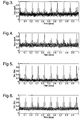
- Figure 5 shows a detection statistic plotted against time for a short segment of off-air data processed as for Figure 3.
- Figure 6 is equivalent to Figure 5 except that it was obtained from data processed using the adaptive basis function set in accordance with the invention.
- the detection statistic is a parameter that lies between 0 and 1; it is used to indicate whether or not a signal has been successfully detected.
- a minimum threshold for detection to be said to occur was set as 0.4.
- Figures 3 to 6 show that this embodiment of the invention works satisfactorily with the STANAG signal being detected.
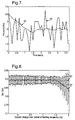
- Figure 7 shows evolution of frequency estimates as a function of time over a longer segment of off-air data compared to that used for Figures 3 to 6.
- a first curve 50 shows the frequency as tracked by the software modem implementation referred to above, i.e. after timing offset recovery, fine frequency compensation and filtering.
- a second curve 52 curve shows initial frequency estimates on acquisition returned by this embodiment of the invention. These estimates would seem to be in excellent agreement with the true frequency. In this case, frequency estimation was performed in maximum likelihood fashion by correlating the adaptively weighted basis function with sinusoids. This may not be the best option since the signal formed from adaptively weighted basis functions is not necessarily a clean sinusoid. However, as the results indicate, it is reasonable.
- the AFC method of the invention is less demanding than conventional MC-LSQ.
- minimisation of the cost function J requires the inverse correlation matrix( X H X ) -1 of a correlation matrix X H X where X is a data matrix.
- a recursive approach may be adopted.
- a received signal which has been acquired may be stored in a data buffer prior to processing.
- the inverse correlation matrix previously derived recursively using sample vector x(2K-1) is discarded and a new estimate of the true correlation matrix is calculated from accumulated data and used to re-initialise the inverse of the correlation matrix for further recursive computations for sample times 2K+1 to 3K-1.
- true correlation estimates are formed at times mK where m is an integer and used to initialise the recursive computation for times mK +1 to (m+1)K-1.
- Recursive computations generally tend to build up numerical errors, but in this case the problem is circumvented by the periodic re-initialisation of the inverse of the correlation matrix.
- a correlation matrix X H X of a sample vector outer products x ( k ) x H (k) can be inverted.
- an inverse correlation matrix can be formed recursively via a recursive least squares (RLS) approach, as in the Haykin reference previously given.
- the table below appear the numbers of arithmetic operations required to carry out the various steps of calculating P (n). In this connection, the square root of a real number is assumed to take Q operations and finding the reciprocal of this number is also assumed to take Q operations.
- ⁇ is a "forget factor" of known kind, and is usually in the range 0.95 to 1. If less than 1, it has the effect of progressively diminishing the effect of older data so that the calculation in Table 2 is weighted in favour of more recent data.
- ⁇ is set to 1, which weights all data equally.
- the received signal may also exhibit a rate-of-change of Doppler shift, i.e. Doppler rate.
- Doppler rate is linear with time t, it can be represented by ⁇ t, where ⁇ is a constant, the Doppler rate in Hz/s.
- r m (t)at the mth antenna element s ⁇ t - ⁇ m ⁇ e - j ⁇ 2 ⁇ ⁇ ⁇ f c ⁇ t + ⁇ b t ⁇ e - j ⁇ 2 ⁇ ⁇ ⁇ ft m t
- Equation (15) has a spatial term e -j2 ⁇ f ⁇ m (t) (controlled by. ⁇ m (t)), and this term is essentially static over the duration of the training sequence. That is, in Equation (12), f b (t) is very small compared to f c in Equation (11).
- the signal phase spatial component for the mth antenna element e -j2 ⁇ ft ⁇ m (t) e -j2 ⁇ f ( d / c )( m-1 ) sin ⁇ ( t ) , where d is the inter-antenna element spacing, c is the velocity of light and ⁇ ( t ) is the possibly (but not necessarily) time-varying angle of arrival of a signal to be detected at the receiver.
- An antenna element at an edge of the M-antenna array is taken to be a phase reference for all antenna elements (i.e. 0 ⁇ m ⁇ M- 1).
- Equation (16) The approximation of the right of Equation (16) holds good if f b (t) is very small compared to f c , which will usually be satisfied in practice. In which case, it is only necessary to consider how to compensate for the time-varying Doppler term, f b (t), in time and not space, i.e. via the adaptive basis function method described with reference to Equation (3).
- the relationship between the maximum Doppler rate that can be tolerated and the maximum frequency span of the sinusoidal basis functions is [(( ⁇ K/f s )+f d )] ⁇ f max , where f d is the Doppler offset, f s is the sample rate, K is the number of samples in a processing window defined by the length of the training sequence. That is, the invention can cope with a degree of Doppler offset inherently, provided that the sum of the Doppler offset and the change in Doppler offset over the duration of the training sequence does not lead to a frequency that lies outside the maximum frequency span of the set of basis functions.
- an appropriate basis can be constructed as described above, for example, from a data matrix A of complex sinusoids and its SVD (or other methods as mentioned earlier).
- the received signal was an HF standard NATO Agreement 4285 signal with signal-to-noise-ratio 3 dB, incident at 30° on an antenna array with six antenna elements arranged with centres in a straight line spaced by half-wavelength intervals.
- the situation which was envisaged was a fixed Doppler offset of 32 Hz and a Doppler rate varying from -100 Hz/s to +100 Hz/s and ten successive training periods.
- An initial 80 symbols of a 256 symbol data frame were used as a training sequence.
- the frequency span which the basis functions were designed to cover in the earlier embodiment was -75 Hz to + 75 Hz, so it will accommodate the above most negative value of Doppler offset.
- a detection statistic provides a measure of performance with a threshold of 0.4.
- Figure 8 shows two curves 60 and 62 of detection statistics for different MC-LSQ methods plotted against Doppler change in frequency over a training period.
- Curve 60 was calculated for a case where a theoretical ideal Doppler compensation had been implemented from knowledge of offset and rate, and curve 62 is for Doppler compensation using the MC-LSQ method of the invention incorporating adaptive basis function combining.
- the error bars indicate a standard deviation of the detection statistic averaged over detections in the ten successive training periods.
- the abscissa is quantified in terms of values of the Doppler change over the duration of a single training sequence; the total change will be 10 times these values.
- Curve 60 is the best detection performance that can be achieved.
- the above adaptive Doppler offset compensation technique was designed to render initial detection/acquisition of a signal of interest relatively insensitive to Doppler effects: synthesis of a Doppler component suitable for the signal recovery stage was not originally required. Estimation of the Doppler rate is likely to prove more difficult than recovery of Doppler offset. For example, the prior art methods given in the four references below require that the signal used to estimate the Doppler rate is a true sinusoid.
- Unwrapped phase is a term of art for absolute phase, i.e. not merely phase with a value in the range 0 to 2 ⁇ , but including also an appropriate integer multiple of 2 ⁇ .
- ⁇ kT s ⁇ 0 + ⁇ d ⁇ kT s + 0.5 ⁇ ⁇ ⁇ d ⁇ k 2 ⁇ T s 2
- ⁇ 0 is the phase of a signal at a reference antenna element at an edge of the antenna array
- k is a sample time index
- T s is a sample time interval between successive samples and other terms are as previously defined.
- J ⁇ ⁇ ⁇ x - Gv ⁇ 2 + ⁇ ⁇ ⁇ * ⁇ x H ⁇ x ⁇ ⁇ - 1
- G is a matrix equal to a product CF
- C is a (K,K) diagonal matrix with a training sequence (without frequency shift), c , on its diagonal
- F is a (K,P) matrix with columns which are appropriately selected basis functions as described previously
- v is a vector of weights which are adaptive to minimise J
- * indicates a complex conjugate.
- a detection statistic is now defined to provide a measure of degree of success of signal acquisition. There is a variety of possible detection statistics.
- the Doppler offset can be found as previously described for the multi-channel case: e.g. a correlation of the complex conjugate transpose g H of g with sinusoidal functions s ( f ) that span the frequency uncertainty region is performed to determine which frequency is a best match to the frequency offset between the signal and the receiver LO.
- Adaptive Doppler rate compensation can also be implemented for a single-antenna receiver in a similar way to that for a multiple antenna receiver. Also, an initial detection or acquisition search may be modified to cover a range of time delays.
- v ⁇ is a vector of vectors v 1 etc.
- Adaptive Doppler compensation for a single-channel direct sequence spread-spectrum (DS-SS) receiver may be achieved as follows. For illustrative purposes, consider the case of a symbol-periodic DS-SS system, i.e. where the length of the spreading code (defined earlier) in chips is LT c , where L is the number of chips in the spreading code and T c is the time duration of a chip. For illustrative purposes it is assumed that there is no multipath and that synchronisation has been achieved.
- UMTS has a training sequence of bits referred to as a pilot signal, of which each receiver has a replica referred to as a replica code. Received signal samples will be collected into a vector x and samples of the receiver's replica code collected into another vector c .
- a Doppler frequency uncertainty space ( ⁇ f ⁇
- imag indicates that an imaginary part of a receiver sample correlation product is taken since the pilot signal is expected to reside on a quadrature or "Q" channel
- diag indicates that the subsequent terms in parenthesis are diagonal elements of a diagonal matrix
- o denotes "element-wise” multiplication, i.e.
- Results for adaptive compensation for Doppler shift using a receiver with a single antenna were obtained as follows.
- the acquisition of a single-channel binary phase shift keying (BPSK) signal of signal-to-noise ratio (SNR) 5 dB was simulated.
- This signal was filtered on transmit and receive with a root-raised cosine (RRC) filter of roll-off 0.2.
- RRC filter impulse response truncated to 10 symbols There were 4 samples per symbol (RRC filter impulse response truncated to 10 symbols) and the SNR was set at the output of the receive filter.
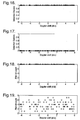
- Results are shown in Figures 11 and 12, which are plots of SNR on acquisition as a function of normalised Doppler offset ( ⁇ f d T) on a logarithmic scale for training sequences of length 30 and 100 symbols respectively, each averaged over one hundred experimental runs.
- curves 80 and 90 show how SNR varies in the absence of any frequency compensation, i.e. the SNR falls away as normalised Doppler increases to 10 -2 .
- Curves 82 and 92 show how SNR varies if adaptive basis function frequency compensation in accordance with the invention is used: these curves demonstrate that a virtually constant and high SNR is maintained for the entire range of normalised Doppler, i.e. 10 -5 to 10 -1 .
- Table 3 shows sizes of basis sets of frequency functions used in frequency compensation in accordance with the invention to obtain the results shown in Figures 11 and 12.
- Table 3 Size of basis set as a function of normalised Doppler and training sequence length. Normalised Doppler Figure 11 30 training symbols Figure 12 100 training symbols 1.0e-05 1 1 1 1.0e-04 1 1 1.0e-03 1 2 1.0e-02 2 4 1.0e-01 8 23
- Table 4 shows estimated mean normalised Dopplers ("est") and true equivalents ("true”). It can be seen that these mean values are within 1% of true values in three out of four cases, and within 5% in the fourth case. Table 4: True and estimated normalised Dopplers. Training symbols Normalised Doppler Normalised Doppler 30: Figure 11 True: 0.01 est 0.009536 True 0.1 est 0.09952 100: Figure 12 True 0.01 est 0.009928 True 0.1 est 0.1
- the method of the invention was incorporated in a software implementation of a single-channel HF STANAG 4285 modem and run with off-air data.
- a STANAG signal was employed which had a frame format (256 symbols) with a period of 106.67 ms and a channel symbol rate of 2.4 kilosymbols/s. Acquisition was performed using a training sequence of 80 symbols that was a periodic repetition of a 31-chip m-sequence (31+31+18) as published in the Standardization Agreement, North Atlantic Treaty Organization, Military Agency for Standardization, "Characteristics of 1200/2400/3600 bits per second single tone modulators/demodulators for HF radio links", 1989.
- the correlation function has a main peak flanked by subsidiary peaks 31 symbols either side.
- the detection method used searched for two correlation peaks 31 symbols apart.
- a correlation coefficient alone is shown in Figures 13 and 14 plotted against time for a short segment of off-air data.
- Figure 13 shows the correlation coefficient for a received signal correlated with the training sequence for a zero Doppler offset.
- Figure 14 shows the correlation coefficient for a received signal when using the method of the invention (with seven basis functions to cover Doppler offsets up to a maximum ⁇ f d of 75 Hz.
- the invention operates satisfactorily, as the STANAG signal is detected.
- Figure 15 shows frequency offset estimates over a segment of off-air data plotted against time.
- a first curve 110 shows "true" frequency offset as tracked by a software modem implementation, i.e. after timing offset recovery, fine frequency compensation and filtering.
- a second curve 112 shows raw or initial frequency offset estimates on acquisition obtained by the method of the invention. As can be seen, these initial frequency estimates are in good agreement with the true frequency offset.
- initial detection or acquisition search may be modified to cover a range of time delays as well as incorporating adaptive Doppler compensation.
- UMTS universal mobile telephone systems
- a simulation of the universal mobile telephone systems (UMTS) uplink i.e. handset to base station, was implemented using the adaptive frequency compensation method of the invention.
- UMTS universal mobile telephone systems
- ten UMTS emitters were uniformly distributed in distance between 1km and 5km from a base-station and multipath and channel Doppler spread were ignored.
- the simulation employed power control as disclosed by Morelli M. in "Doppler-Rate Estimation for Burst Digital Transmission", IEEE Trans. Commun., Vol. 50, No. 5, May 2002, pp707-10 .
- Figures 16 and 17 indicate detection performance for a particular emitter over the pilot bit sequence with and without the adaptive frequency compensation method of the invention respectively.
- a detection statistic is plotted against Doppler offset, and a detection statistic value of 1 indicates that the 8-bit pilot bit sequence was correctly detected and 0 indicates it was not.
- Figure 16 shows that 100% of the values were 1, and therefore the adaptive frequency compensation method of the invention always detected the pilot bit sequence correctly.
- Figure 17 shows that 100% of the values were 0, indicating that without frequency compensation the pilot bit sequence was never detected.
- Figures 18 and 19 show pilot bit counts from which the results shown in Figures 16 and 17 respectively were derived.
- Figure 18 shows that all eight pilot bits were always detected using the adaptive frequency compensation method of the invention.
- Figure 19 shows that, without frequency compensation, the number of pilot bits detected varied from one to seven but all eight pilot bits were never detected.
Landscapes
- Engineering & Computer Science (AREA)
- Computer Networks & Wireless Communication (AREA)
- Signal Processing (AREA)
- Radio Transmission System (AREA)
- Input Circuits Of Receivers And Coupling Of Receivers And Audio Equipment (AREA)
- Noise Elimination (AREA)
- Variable-Direction Aerials And Aerial Arrays (AREA)
- Channel Selection Circuits, Automatic Tuning Circuits (AREA)
- Circuits Of Receivers In General (AREA)
Applications Claiming Priority (2)
| Application Number | Priority Date | Filing Date | Title |
|---|---|---|---|
| GBGB0403762.8A GB0403762D0 (en) | 2004-02-20 | 2004-02-20 | Frequency compensated communications reception |
| PCT/GB2005/000509 WO2005081484A1 (en) | 2004-02-20 | 2005-02-15 | Frequency compensated communications reception |
Publications (2)
| Publication Number | Publication Date |
|---|---|
| EP1716683A1 EP1716683A1 (en) | 2006-11-02 |
| EP1716683B1 true EP1716683B1 (en) | 2008-01-23 |
Family
ID=32040058
Family Applications (1)
| Application Number | Title | Priority Date | Filing Date |
|---|---|---|---|
| EP05708328A Expired - Lifetime EP1716683B1 (en) | 2004-02-20 | 2005-02-15 | Frequency compensated communications reception |
Country Status (7)
| Country | Link |
|---|---|
| US (1) | US7715499B2 (enExample) |
| EP (1) | EP1716683B1 (enExample) |
| JP (1) | JP4805849B2 (enExample) |
| AT (1) | ATE385116T1 (enExample) |
| DE (1) | DE602005004511T2 (enExample) |
| GB (1) | GB0403762D0 (enExample) |
| WO (1) | WO2005081484A1 (enExample) |
Cited By (1)
| Publication number | Priority date | Publication date | Assignee | Title |
|---|---|---|---|---|
| CN107171748A (zh) * | 2017-05-11 | 2017-09-15 | 电子科技大学 | 欠采样的多阵列协同测频与直接定位方法 |
Families Citing this family (7)
| Publication number | Priority date | Publication date | Assignee | Title |
|---|---|---|---|---|
| WO2008082344A1 (en) * | 2007-01-04 | 2008-07-10 | Telefonaktiebolaget L M Ericsson (Publ) | Method and apparatus for improving transmission efficiency in a mobile radio communications system |
| US7978135B2 (en) * | 2008-02-15 | 2011-07-12 | Atc Technologies, Llc | Antenna beam forming systems/methods using unconstrained phase response |
| US8339308B2 (en) * | 2009-03-16 | 2012-12-25 | Atc Technologies Llc | Antenna beam forming systems, methods and devices using phase adjusted least squares beam forming |
| WO2012114413A1 (ja) * | 2011-02-24 | 2012-08-30 | 三洋電機株式会社 | 受信装置 |
| CN102332947B (zh) * | 2011-07-07 | 2014-07-30 | 清华大学 | 基于虚拟天线阵列的多普勒扩展补偿器及补偿方法 |
| US11125870B2 (en) * | 2016-08-26 | 2021-09-21 | Nec Corporation | Moving-target detection system and moving-target detection method |
| CN113541650B (zh) * | 2021-06-23 | 2024-03-15 | 苏州大学 | 稀疏线性约束递归最大相关熵自适应滤波器 |
Family Cites Families (16)
| Publication number | Priority date | Publication date | Assignee | Title |
|---|---|---|---|---|
| US5297165A (en) * | 1990-07-06 | 1994-03-22 | Nippon Telegraph And Telephone Corporation | Equalizer for radio receive signal |
| DE4219311C2 (de) | 1991-06-13 | 1996-03-07 | Sony Magnescale Inc | Verschiebungsdetektor |
| CA2110881C (en) | 1992-12-09 | 1998-07-28 | Kyo Takahashi | Adaptive equalizer capable of compensating for carrier frequency offset |
| JP3587985B2 (ja) * | 1998-02-19 | 2004-11-10 | 三菱電機株式会社 | アダプティブアンテナ |
| US6331996B1 (en) | 1998-05-28 | 2001-12-18 | Lucent Technologies Inc. | Channel synchronization and impulse sounding in the presence of frequency offset |
| JP3678023B2 (ja) * | 1998-10-23 | 2005-08-03 | 株式会社日立製作所 | 符号分割多元接続方式移動通信システムにおける通信装置 |
| US6445751B1 (en) * | 1999-01-29 | 2002-09-03 | Lucent Technologies Inc. | Estimation of frequency offset in a communication system |
| US6393073B1 (en) * | 1999-06-28 | 2002-05-21 | Raytheon Company | Method of frequency offset estimation and correction for adaptive antennas |
| US6795392B1 (en) * | 2000-03-27 | 2004-09-21 | At&T Corp. | Clustered OFDM with channel estimation |
| JP2001285189A (ja) * | 2000-04-03 | 2001-10-12 | Sanyo Electric Co Ltd | 無線基地局、プログラム記憶媒体 |
| FI20001133A7 (fi) * | 2000-05-12 | 2001-11-13 | Nokia Corp | Menetelmä päätelaitteiden ja yhteysaseman välisen tiedonsiirron järjestämiseksi tiedonsiirtojärjestelmässä |
| SE517039C2 (sv) * | 2000-05-31 | 2002-04-02 | Bjoern Ottersten | Anordning och metod för kanalinterferensdämpning |
| US6650714B2 (en) | 2000-11-30 | 2003-11-18 | Arraycomm, Inc. | Spatial processing and timing estimation using a training sequence in a radio communications system |
| JP3669915B2 (ja) * | 2000-10-06 | 2005-07-13 | 株式会社国際電気通信基礎技術研究所 | アレーアンテナの制御装置及び制御方法 |
| JP3779554B2 (ja) * | 2001-03-13 | 2006-05-31 | 株式会社エヌ・ティ・ティ・ドコモ | 周波数オフセット推定方法及び周波数オフセット推定器 |
| JP4020420B2 (ja) * | 2002-07-22 | 2007-12-12 | 小島プレス工業株式会社 | 直交周波数多重信号を受信する装置、及び方法 |
-
2004
- 2004-02-20 GB GBGB0403762.8A patent/GB0403762D0/en not_active Ceased
-
2005
- 2005-02-15 JP JP2006553647A patent/JP4805849B2/ja not_active Expired - Fee Related
- 2005-02-15 WO PCT/GB2005/000509 patent/WO2005081484A1/en not_active Ceased
- 2005-02-15 AT AT05708328T patent/ATE385116T1/de not_active IP Right Cessation
- 2005-02-15 US US10/589,530 patent/US7715499B2/en not_active Expired - Fee Related
- 2005-02-15 EP EP05708328A patent/EP1716683B1/en not_active Expired - Lifetime
- 2005-02-15 DE DE602005004511T patent/DE602005004511T2/de not_active Expired - Lifetime
Cited By (2)
| Publication number | Priority date | Publication date | Assignee | Title |
|---|---|---|---|---|
| CN107171748A (zh) * | 2017-05-11 | 2017-09-15 | 电子科技大学 | 欠采样的多阵列协同测频与直接定位方法 |
| CN107171748B (zh) * | 2017-05-11 | 2020-11-13 | 电子科技大学 | 欠采样的多阵列协同测频与直接定位方法 |
Also Published As
| Publication number | Publication date |
|---|---|
| ATE385116T1 (de) | 2008-02-15 |
| US20070165752A1 (en) | 2007-07-19 |
| EP1716683A1 (en) | 2006-11-02 |
| DE602005004511D1 (de) | 2008-03-13 |
| JP2007523553A (ja) | 2007-08-16 |
| WO2005081484A1 (en) | 2005-09-01 |
| US7715499B2 (en) | 2010-05-11 |
| DE602005004511T2 (de) | 2009-01-22 |
| JP4805849B2 (ja) | 2011-11-02 |
| GB0403762D0 (en) | 2004-03-24 |
Similar Documents
| Publication | Publication Date | Title |
|---|---|---|
| US6031881A (en) | Method for mitigating multipath effects in radio ranging systems | |
| Swindlehurst | Time delay and spatial signature estimation using known asynchronous signals | |
| US7379757B2 (en) | System and method for estimating the multi-path delays in a signal using a spatially blind antenna array | |
| EP1376150B1 (en) | Radio positioning system using interference cancellation | |
| US7126533B2 (en) | Direction-finding for multiple cochannel sources | |
| JP3600459B2 (ja) | 電波到来方向推定方法及びその装置 | |
| US5982809A (en) | Method and apparatus for carrier recovery and compensation in spread spectrum communications | |
| US6445692B1 (en) | Blind adaptive algorithms for optimal minimum variance CDMA receivers | |
| US20030054845A1 (en) | Enhanced time of arrival estimation using reduced complexity optimal processing | |
| EP1716683B1 (en) | Frequency compensated communications reception | |
| US20040101073A1 (en) | Method and apparatus for estimating response characteristic, and receiving method and receiver utilizing the same | |
| US5517531A (en) | Kernel adaptive interference suppression system | |
| CN117060985B (zh) | 一种船载双天线pcma系统信号重捕方法及装置 | |
| US6353731B1 (en) | Method and measurement configuration for measuring the characteristics of radio channels | |
| WO1998038772A1 (en) | Channel impulse response estimation using singular value decomposition | |
| US7006800B1 (en) | Signal-to-noise ratio (SNR) estimator in wireless fading channels | |
| US20170195158A1 (en) | System and Method for Performing Initial Synchronization During Wireless Sector Searches | |
| Rashid et al. | Multitarget joint delay and Doppler-shift estimation in bistatic passive radar | |
| Wang et al. | Performance of correlation-based frequency estimation methods in the presence of multiplicative noise | |
| Kulmer et al. | Delay estimation in presence of dense multipath | |
| EP1910862B1 (en) | Delay estimation apparatus and method | |
| Stock et al. | Correlation-based doppler shift estimation for opportunistic leo-pnt with starlink signals | |
| KR102574425B1 (ko) | 기저대역의 ofdm 수신 장치 및 그 장치에서의 샘플 클럭 오류 추정 방법 | |
| Öktem et al. | Power delay Doppler profile fingerprinting for mobile localization in NLOS | |
| US6683569B1 (en) | Non-linear technique for mitigating correlation timing errors due to multipath signals |
Legal Events
| Date | Code | Title | Description |
|---|---|---|---|
| PUAI | Public reference made under article 153(3) epc to a published international application that has entered the european phase |
Free format text: ORIGINAL CODE: 0009012 |
|
| 17P | Request for examination filed |
Effective date: 20060807 |
|
| AK | Designated contracting states |
Kind code of ref document: A1 Designated state(s): AT BE BG CH CY CZ DE DK EE ES FI FR GB GR HU IE IS IT LI LT LU MC NL PL PT RO SE SI SK TR |
|
| 17Q | First examination report despatched |
Effective date: 20061219 |
|
| DAX | Request for extension of the european patent (deleted) | ||
| RAP1 | Party data changed (applicant data changed or rights of an application transferred) |
Owner name: VOCALCOMM GROUP, LLC |
|
| GRAP | Despatch of communication of intention to grant a patent |
Free format text: ORIGINAL CODE: EPIDOSNIGR1 |
|
| GRAS | Grant fee paid |
Free format text: ORIGINAL CODE: EPIDOSNIGR3 |
|
| GRAA | (expected) grant |
Free format text: ORIGINAL CODE: 0009210 |
|
| AK | Designated contracting states |
Kind code of ref document: B1 Designated state(s): AT BE BG CH CY CZ DE DK EE ES FI FR GB GR HU IE IS IT LI LT LU MC NL PL PT RO SE SI SK TR |
|
| REG | Reference to a national code |
Ref country code: GB Ref legal event code: FG4D |
|
| REG | Reference to a national code |
Ref country code: CH Ref legal event code: EP |
|
| REG | Reference to a national code |
Ref country code: IE Ref legal event code: FG4D |
|
| REF | Corresponds to: |
Ref document number: 602005004511 Country of ref document: DE Date of ref document: 20080313 Kind code of ref document: P |
|
| NLV1 | Nl: lapsed or annulled due to failure to fulfill the requirements of art. 29p and 29m of the patents act | ||
| PG25 | Lapsed in a contracting state [announced via postgrant information from national office to epo] |
Ref country code: CH Free format text: LAPSE BECAUSE OF FAILURE TO SUBMIT A TRANSLATION OF THE DESCRIPTION OR TO PAY THE FEE WITHIN THE PRESCRIBED TIME-LIMIT Effective date: 20080123 Ref country code: ES Free format text: LAPSE BECAUSE OF FAILURE TO SUBMIT A TRANSLATION OF THE DESCRIPTION OR TO PAY THE FEE WITHIN THE PRESCRIBED TIME-LIMIT Effective date: 20080504 Ref country code: FI Free format text: LAPSE BECAUSE OF FAILURE TO SUBMIT A TRANSLATION OF THE DESCRIPTION OR TO PAY THE FEE WITHIN THE PRESCRIBED TIME-LIMIT Effective date: 20080123 Ref country code: IS Free format text: LAPSE BECAUSE OF FAILURE TO SUBMIT A TRANSLATION OF THE DESCRIPTION OR TO PAY THE FEE WITHIN THE PRESCRIBED TIME-LIMIT Effective date: 20080523 Ref country code: LI Free format text: LAPSE BECAUSE OF FAILURE TO SUBMIT A TRANSLATION OF THE DESCRIPTION OR TO PAY THE FEE WITHIN THE PRESCRIBED TIME-LIMIT Effective date: 20080123 |
|
| REG | Reference to a national code |
Ref country code: CH Ref legal event code: PL |
|
| PG25 | Lapsed in a contracting state [announced via postgrant information from national office to epo] |
Ref country code: AT Free format text: LAPSE BECAUSE OF FAILURE TO SUBMIT A TRANSLATION OF THE DESCRIPTION OR TO PAY THE FEE WITHIN THE PRESCRIBED TIME-LIMIT Effective date: 20080123 Ref country code: BG Free format text: LAPSE BECAUSE OF FAILURE TO SUBMIT A TRANSLATION OF THE DESCRIPTION OR TO PAY THE FEE WITHIN THE PRESCRIBED TIME-LIMIT Effective date: 20080423 |
|
| PG25 | Lapsed in a contracting state [announced via postgrant information from national office to epo] |
Ref country code: PL Free format text: LAPSE BECAUSE OF FAILURE TO SUBMIT A TRANSLATION OF THE DESCRIPTION OR TO PAY THE FEE WITHIN THE PRESCRIBED TIME-LIMIT Effective date: 20080123 Ref country code: PT Free format text: LAPSE BECAUSE OF FAILURE TO SUBMIT A TRANSLATION OF THE DESCRIPTION OR TO PAY THE FEE WITHIN THE PRESCRIBED TIME-LIMIT Effective date: 20080623 Ref country code: SI Free format text: LAPSE BECAUSE OF FAILURE TO SUBMIT A TRANSLATION OF THE DESCRIPTION OR TO PAY THE FEE WITHIN THE PRESCRIBED TIME-LIMIT Effective date: 20080123 Ref country code: BE Free format text: LAPSE BECAUSE OF FAILURE TO SUBMIT A TRANSLATION OF THE DESCRIPTION OR TO PAY THE FEE WITHIN THE PRESCRIBED TIME-LIMIT Effective date: 20080123 |
|
| ET | Fr: translation filed | ||
| PG25 | Lapsed in a contracting state [announced via postgrant information from national office to epo] |
Ref country code: MC Free format text: LAPSE BECAUSE OF NON-PAYMENT OF DUE FEES Effective date: 20080228 Ref country code: CZ Free format text: LAPSE BECAUSE OF FAILURE TO SUBMIT A TRANSLATION OF THE DESCRIPTION OR TO PAY THE FEE WITHIN THE PRESCRIBED TIME-LIMIT Effective date: 20080123 Ref country code: DK Free format text: LAPSE BECAUSE OF FAILURE TO SUBMIT A TRANSLATION OF THE DESCRIPTION OR TO PAY THE FEE WITHIN THE PRESCRIBED TIME-LIMIT Effective date: 20080123 Ref country code: SK Free format text: LAPSE BECAUSE OF FAILURE TO SUBMIT A TRANSLATION OF THE DESCRIPTION OR TO PAY THE FEE WITHIN THE PRESCRIBED TIME-LIMIT Effective date: 20080123 Ref country code: SE Free format text: LAPSE BECAUSE OF FAILURE TO SUBMIT A TRANSLATION OF THE DESCRIPTION OR TO PAY THE FEE WITHIN THE PRESCRIBED TIME-LIMIT Effective date: 20080423 Ref country code: NL Free format text: LAPSE BECAUSE OF FAILURE TO SUBMIT A TRANSLATION OF THE DESCRIPTION OR TO PAY THE FEE WITHIN THE PRESCRIBED TIME-LIMIT Effective date: 20080123 |
|
| PG25 | Lapsed in a contracting state [announced via postgrant information from national office to epo] |
Ref country code: RO Free format text: LAPSE BECAUSE OF FAILURE TO SUBMIT A TRANSLATION OF THE DESCRIPTION OR TO PAY THE FEE WITHIN THE PRESCRIBED TIME-LIMIT Effective date: 20080123 |
|
| PLBE | No opposition filed within time limit |
Free format text: ORIGINAL CODE: 0009261 |
|
| STAA | Information on the status of an ep patent application or granted ep patent |
Free format text: STATUS: NO OPPOSITION FILED WITHIN TIME LIMIT |
|
| 26N | No opposition filed |
Effective date: 20081024 |
|
| PG25 | Lapsed in a contracting state [announced via postgrant information from national office to epo] |
Ref country code: IE Free format text: LAPSE BECAUSE OF NON-PAYMENT OF DUE FEES Effective date: 20080215 Ref country code: LT Free format text: LAPSE BECAUSE OF FAILURE TO SUBMIT A TRANSLATION OF THE DESCRIPTION OR TO PAY THE FEE WITHIN THE PRESCRIBED TIME-LIMIT Effective date: 20080123 Ref country code: EE Free format text: LAPSE BECAUSE OF FAILURE TO SUBMIT A TRANSLATION OF THE DESCRIPTION OR TO PAY THE FEE WITHIN THE PRESCRIBED TIME-LIMIT Effective date: 20080123 |
|
| PG25 | Lapsed in a contracting state [announced via postgrant information from national office to epo] |
Ref country code: CY Free format text: LAPSE BECAUSE OF FAILURE TO SUBMIT A TRANSLATION OF THE DESCRIPTION OR TO PAY THE FEE WITHIN THE PRESCRIBED TIME-LIMIT Effective date: 20080123 |
|
| PG25 | Lapsed in a contracting state [announced via postgrant information from national office to epo] |
Ref country code: IT Free format text: LAPSE BECAUSE OF FAILURE TO SUBMIT A TRANSLATION OF THE DESCRIPTION OR TO PAY THE FEE WITHIN THE PRESCRIBED TIME-LIMIT Effective date: 20080123 |
|
| PG25 | Lapsed in a contracting state [announced via postgrant information from national office to epo] |
Ref country code: LU Free format text: LAPSE BECAUSE OF NON-PAYMENT OF DUE FEES Effective date: 20080215 Ref country code: HU Free format text: LAPSE BECAUSE OF FAILURE TO SUBMIT A TRANSLATION OF THE DESCRIPTION OR TO PAY THE FEE WITHIN THE PRESCRIBED TIME-LIMIT Effective date: 20080724 |
|
| PG25 | Lapsed in a contracting state [announced via postgrant information from national office to epo] |
Ref country code: TR Free format text: LAPSE BECAUSE OF FAILURE TO SUBMIT A TRANSLATION OF THE DESCRIPTION OR TO PAY THE FEE WITHIN THE PRESCRIBED TIME-LIMIT Effective date: 20080123 |
|
| PG25 | Lapsed in a contracting state [announced via postgrant information from national office to epo] |
Ref country code: GR Free format text: LAPSE BECAUSE OF FAILURE TO SUBMIT A TRANSLATION OF THE DESCRIPTION OR TO PAY THE FEE WITHIN THE PRESCRIBED TIME-LIMIT Effective date: 20080424 |
|
| PGFP | Annual fee paid to national office [announced via postgrant information from national office to epo] |
Ref country code: DE Payment date: 20150227 Year of fee payment: 11 |
|
| REG | Reference to a national code |
Ref country code: FR Ref legal event code: PLFP Year of fee payment: 12 |
|
| REG | Reference to a national code |
Ref country code: DE Ref legal event code: R119 Ref document number: 602005004511 Country of ref document: DE |
|
| REG | Reference to a national code |
Ref country code: FR Ref legal event code: PLFP Year of fee payment: 13 |
|
| PG25 | Lapsed in a contracting state [announced via postgrant information from national office to epo] |
Ref country code: DE Free format text: LAPSE BECAUSE OF NON-PAYMENT OF DUE FEES Effective date: 20160901 |
|
| REG | Reference to a national code |
Ref country code: FR Ref legal event code: PLFP Year of fee payment: 14 |
|
| PGFP | Annual fee paid to national office [announced via postgrant information from national office to epo] |
Ref country code: GB Payment date: 20180125 Year of fee payment: 14 |
|
| PGFP | Annual fee paid to national office [announced via postgrant information from national office to epo] |
Ref country code: FR Payment date: 20180118 Year of fee payment: 14 |
|
| GBPC | Gb: european patent ceased through non-payment of renewal fee |
Effective date: 20190215 |
|
| PG25 | Lapsed in a contracting state [announced via postgrant information from national office to epo] |
Ref country code: GB Free format text: LAPSE BECAUSE OF NON-PAYMENT OF DUE FEES Effective date: 20190215 |
|
| PG25 | Lapsed in a contracting state [announced via postgrant information from national office to epo] |
Ref country code: FR Free format text: LAPSE BECAUSE OF NON-PAYMENT OF DUE FEES Effective date: 20190228 |