US7006800B1 - Signal-to-noise ratio (SNR) estimator in wireless fading channels - Google Patents
Signal-to-noise ratio (SNR) estimator in wireless fading channels Download PDFInfo
- Publication number
- US7006800B1 US7006800B1 US10/457,057 US45705703A US7006800B1 US 7006800 B1 US7006800 B1 US 7006800B1 US 45705703 A US45705703 A US 45705703A US 7006800 B1 US7006800 B1 US 7006800B1
- Authority
- US
- United States
- Prior art keywords
- vector
- signal
- circuit
- energy
- noise
- Prior art date
- Legal status (The legal status is an assumption and is not a legal conclusion. Google has not performed a legal analysis and makes no representation as to the accuracy of the status listed.)
- Active, expires
Links
Images


Classifications
-
- H—ELECTRICITY
- H04—ELECTRIC COMMUNICATION TECHNIQUE
- H04B—TRANSMISSION
- H04B17/00—Monitoring; Testing
- H04B17/30—Monitoring; Testing of propagation channels
- H04B17/309—Measuring or estimating channel quality parameters
- H04B17/336—Signal-to-interference ratio [SIR] or carrier-to-interference ratio [CIR]
-
- H—ELECTRICITY
- H04—ELECTRIC COMMUNICATION TECHNIQUE
- H04B—TRANSMISSION
- H04B17/00—Monitoring; Testing
- H04B17/20—Monitoring; Testing of receivers
- H04B17/26—Monitoring; Testing of receivers using historical data, averaging values or statistics
-
- H—ELECTRICITY
- H04—ELECTRIC COMMUNICATION TECHNIQUE
- H04B—TRANSMISSION
- H04B17/00—Monitoring; Testing
- H04B17/30—Monitoring; Testing of propagation channels
- H04B17/382—Monitoring; Testing of propagation channels for resource allocation, admission control or handover
Definitions
- the present invention relates generally to wide-band code division multiple access (WCDMA) systems, and more particularly to turbo decoding likelihood ratio estimation in WCDMA systems.
- WCDMA wide-band code division multiple access
- the generation and transmission of signals invariably involves the introduction of noise into signals, which degrades the quality of the signals and may prevent accurate decoding of the signals.
- a determination (or an accurate estimate) of the noise contained in the system is useful for enhancing the signal-to-noise ratio of a received signal.
- Wide-band code division multiple access (WCDMA) systems such as base stations and mobile terminals, employ a turbo decoder, which uses signal noise power values to enhance accurate decoding of the degraded signals that the WCDMA systems receive.
- WCDMA systems control power transmission by measuring the received Signal-to-Noise power Ratio (SNR). Accordingly, an accurate estimate of SNR improves the power control and subsequently increases the system performance and capacity.
- SNR Signal-to-Noise power Ratio
- FIG. 1 is a diagram of a generalized WCDMA system comprising a Base Station and a Mobile Terminal used in accordance with the present invention.
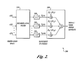
- FIG. 2 is a block diagram for a signal-to-noise estimator for estimating the signal-to-noise ratio in wireless fading channels in accordance with the present invention.
- FIG. 3 is a flow diagram for estimating the signal-to-noise ratio in wireless fading channels in accordance with the present invention.
- the meaning of “a,” “an,” and “the” includes plural reference, the meaning of “in” includes “in” and “on.”
- the term “connected” means a direct electrical connection between the items connected, without any intermediate devices.
- the term “coupled” means either a direct electrical connection between the items connected, or an indirect connection through one or more passive or active intermediary devices.
- the term “circuit” means either a single component or a multiplicity of components, either active and/or passive, that are coupled together to provide a desired function.
- signal means at least one current, voltage, or data signal.
- the present invention is directed towards a signal-to-noise estimator for estimating the Signal-to-Noise power Ratio (SNR) of mobile wireless systems in wireless fading channels.
- the estimator is applied to likelihood ratio estimation of turbo decoders in Third Generation Wideband Code Division Multiple Access (WCDMA) receivers in Base Stations and Mobile Terminals.
- WCDMA Wideband Code Division Multiple Access
- the SNR estimate is used for transmission power control in WCDMA systems.
- Time-multiplexed samples of pilot symbols from a wireless receiver are supplied to the estimator to obtain individual estimates of signal power and/or noise power and/or signal-to-noise power ratio.
- the estimator uses a de-correlating filter in which the coefficients are known functions (such as eigen-vectors) of the auto-correlation matrix for a wireless multi-path fading channel.
- the decorrelating filter is used by the estimator to map an observation vector (from received pilot symbols) into a set of statistically independent samples (“sufficient statistics”).
- the energy of each vector component is computed individually and combined (weighted sum) to produce estimates of the signal and interference power estimates.
- the weighting factors depend on the type of estimators, such as maximum likelihood and sub-space methods.
- the estimator can produce joint estimations of signal and noise power in wireless channels by using properties of signal and noise sub-spaces to decouple the observation space into orthogonal domains.
- FIG. 1 is a diagram of a generalized WCDMA system comprising a Base Station and a Mobile Terminal, which depicts the usage of the Signal-to-Noise Ratio Estimator in the system.
- System 100 comprises at least one base station (BS) 110 and at least one mobile transmitter (MT).
- Base station 110 comprises the RF transceivers, antennas, and other electrical equipment that are located in each cell site.
- Mobile station 120 is typically a portable wireless communication device, although other configurations are possible.
- BS 110 and MT 120 may transfer voice and data signals between each other and other networks such as the public switched telephone network (PSTN) (not shown), the internet, and the like.
- PSTN public switched telephone network
- BS 110 and MT 120 comprise functional blocks that perform similar functions (although the physical implementations may vary considerably).
- BS 110 and MT 120 comprise Turbo/Channel Decoder 130 , SNR Estimator 140 , Transmission Power Control 150 , Transmitter 160 , and Receiver 170 .
- SNR Estimator 140 operates in response to a signal that is received by Receiver 170 and is used to adjust the power of Transmitter 160 and to improve the performance of the channel decoder 130 .
- FIG. 2 is a block diagram for a signal-to-noise estimator for estimating the signal-to-noise ratio in wireless fading channels in accordance with the present invention.
- Estimator 200 comprises decorrelating filter 210 , a plurality of sufficient statistics generators 220 , and weighted sum generator 203 .
- decorrelating filter 210 receives an observation vector from N (total) received pilot symbols.
- the operation of estimator 200 is generally described with respect to FIG. 2 , while a more detailed description follows with respect to FIG. 3 .
- Decorrelating filter 210 projects the received observation vector into signal and noise subspaces.
- the coefficients of this filter i.e., the projection vectors
- the plurality of sufficient statistics generators ( 120 ) produces a set of N (total) sufficient statistics, which are produced according to the square-magnitude of the outputs of decorrelating filter 210 .
- Weighted sum generator 230 receives the generated sufficient statistics and generates signal and/or noise (“signal/noise”) power estimates in response. Specific sets (in accordance with various estimation algorithms) of weighting coefficients can be used to weight each of the generated N sufficient statistics for producing the signal/noise power estimate.
- FIG. 3 is a flow diagram for estimating the signal-to-noise ratio in wireless fading channels in accordance with the present invention.
- a matched filter receiver or equalizer such as from a “finger” of a rake receiver
- Each slot is typically 10–15 milliseconds, although other durations are possible.
- the outputs are de-multiplexed into data symbols, control symbols, and pilot symbols.
- a number of pilot symbols (in which P is the number of pilot symbols) are de-rotated by the known phase of the transmitted symbols.
- the de-rotated P pilot symbols obtained from a number of successive slots (in which L is the number of successive slots) are assembled in an “observation vector.”
- a “projection vector” is obtained for projection of the observation vector onto orthogonal signal subspaces.
- the projection vector is an array, which is also (typically) of length N.
- the projection vectors (which are used as coefficients of the de-correlating filter) are the N eigen-vectors associated with the auto-correlation matrix of the fading channel.
- the auto-correlation matrix can be assumed to be known beforehand for any given Doppler frequency.
- the Doppler frequency of a mobile transmitted signal is directly proportional to the speed of the mobile and typically introduces phase distortion into the transmitted signal.
- the projection vectors can be obtained by various methods by which the computational load can be reduced and power can be conserved.
- the projection vectors can be pre-calculated for different Doppler frequencies, or for example, obtained by nonlinear interpolation from an estimate of the Doppler frequency.
- a lookup table of pre-calculated sets of coefficients for different Doppler frequencies can be stored in the memory of the mobile.
- a set of coefficients can be selected from the table based on a real-time coarse estimate of the Doppler frequency.
- the coarse estimate can, for example, be divided into low Doppler (around 5 Hz), medium Doppler (around 50 Hz), or High Doppler (around 500 Hz).
- a fixed set of coefficients can be used regardless of the speed of the mobile. The coefficients are selected such that a relatively good performance is achieved over the entire range of mobile speed.
- the N projection vectors can be calculated by interpolation for one or more pre-calculated set(s) of coefficients (projection vectors) for particular Doppler frequencies.
- the particular Doppler frequencies are chosen such that adequate coefficients can be derived using the particular Doppler frequencies.
- the pre-calculated vectors are calculated for frequency f 0 , which is typically a low frequency such as 0 Hz.
- the interpolation coefficients, ⁇ ij and ⁇ ij are obtained by an interpolation algorithm such as a least-squares estimation technique.
- T j Re ( ⁇ tilde over (x) ⁇ j ) 2 +Im ( ⁇ tilde over (x) ⁇ j ) 2
- estimates of signal ( ⁇ ) and interference ( ⁇ 2 ) power are computed.
- N s is the size of signal subspace and ⁇ i 's are the eigen-values (singular values) of the fading channel auto-correlation matrix (which may be calculated off-line or in real-time).
- the weight coefficients obtained from a maximum-likelihood estimator can be produced according to the following equations.
- the weight coefficients obtained from a sub-space estimator can be produced according to the following equations.
- the signal-to-noise power ratio estimate is then calculated by dividing the signal power estimate derived in block 360 by the noise power estimate computed in block 360 .
- weighting coefficients that are used to produce the signal/noise estimate may be produced by methods other than maximum-likelihood or subspace estimations.
- the above specification, examples and data provide a complete description of the manufacture and use of the composition of the invention. Since many embodiments of the invention can be made without departing from the spirit and scope of the invention, the invention resides in the claims hereinafter appended.
Abstract
A signal-to-noise estimator is provided for estimating the signal-to-noise ratio in wireless fading channels. The estimator can be applied to likelihood ratio estimation of turbo decoders in third generation wide-band code division multiple access (WCDMA) systems. Time-multiplexed samples of pilot symbols from a wireless receiver are supplied to the estimator to obtain individual estimates of signal power and/or noise power. The estimator uses a de-correlating filter in which the coefficients are known functions (such as eigen-vectors) of the auto-correlation matrix for a wireless channel. The decorrelating filter is used by the estimator to map an observation vector into a set of statistically independent samples. The energy of each vector component is computed individually and combined to produce an aggregate sum for the vector. The aggregate sum can be subtracted from the pilot tone power in order to produce an estimate of noise power.
Description
The present invention relates generally to wide-band code division multiple access (WCDMA) systems, and more particularly to turbo decoding likelihood ratio estimation in WCDMA systems.
The generation and transmission of signals invariably involves the introduction of noise into signals, which degrades the quality of the signals and may prevent accurate decoding of the signals. A determination (or an accurate estimate) of the noise contained in the system is useful for enhancing the signal-to-noise ratio of a received signal. Wide-band code division multiple access (WCDMA) systems, such as base stations and mobile terminals, employ a turbo decoder, which uses signal noise power values to enhance accurate decoding of the degraded signals that the WCDMA systems receive. Furthermore, WCDMA systems control power transmission by measuring the received Signal-to-Noise power Ratio (SNR). Accordingly, an accurate estimate of SNR improves the power control and subsequently increases the system performance and capacity.
An appreciation of the present invention and its improvements can be obtained by reference to the accompanying drawings, which are briefly summarized below, to the following detailed description of illustrated embodiments of the invention, and to the appended claims.
In the following detailed description of exemplary embodiments of the invention, reference is made to the accompanied drawings, which form a part hereof, and which is shown by way of illustration, specific exemplary embodiments of which the invention may be practiced. These embodiments are described in sufficient detail to enable those skilled in the art to practice the invention, and it is to be understood that other embodiments may be utilized, and other changes may be made, without departing from the spirit or scope of the present invention. The following detailed description is, therefore, not to be taken in a limiting sense, and the scope of the present invention is defined only by the appended claims.
Throughout the specification and claims, the following terms take the meanings explicitly associated herein, unless the context clearly dictates otherwise. The meaning of “a,” “an,” and “the” includes plural reference, the meaning of “in” includes “in” and “on.” The term “connected” means a direct electrical connection between the items connected, without any intermediate devices. The term “coupled” means either a direct electrical connection between the items connected, or an indirect connection through one or more passive or active intermediary devices. The term “circuit” means either a single component or a multiplicity of components, either active and/or passive, that are coupled together to provide a desired function. The term “signal” means at least one current, voltage, or data signal. Referring to the drawings, like numbers indicate like parts throughout the views.
The present invention is directed towards a signal-to-noise estimator for estimating the Signal-to-Noise power Ratio (SNR) of mobile wireless systems in wireless fading channels. The estimator is applied to likelihood ratio estimation of turbo decoders in Third Generation Wideband Code Division Multiple Access (WCDMA) receivers in Base Stations and Mobile Terminals. In addition, the SNR estimate is used for transmission power control in WCDMA systems. Time-multiplexed samples of pilot symbols from a wireless receiver are supplied to the estimator to obtain individual estimates of signal power and/or noise power and/or signal-to-noise power ratio. The estimator uses a de-correlating filter in which the coefficients are known functions (such as eigen-vectors) of the auto-correlation matrix for a wireless multi-path fading channel. The decorrelating filter is used by the estimator to map an observation vector (from received pilot symbols) into a set of statistically independent samples (“sufficient statistics”). The energy of each vector component is computed individually and combined (weighted sum) to produce estimates of the signal and interference power estimates. The weighting factors depend on the type of estimators, such as maximum likelihood and sub-space methods. In various embodiments, the estimator can produce joint estimations of signal and noise power in wireless channels by using properties of signal and noise sub-spaces to decouple the observation space into orthogonal domains.
BS 110 and MT 120 may transfer voice and data signals between each other and other networks such as the public switched telephone network (PSTN) (not shown), the internet, and the like. BS 110 and MT 120 comprise functional blocks that perform similar functions (although the physical implementations may vary considerably). BS 110 and MT 120 comprise Turbo/Channel Decoder 130, SNR Estimator 140, Transmission Power Control 150, Transmitter 160, and Receiver 170. As described in more detail below, SNR Estimator 140 operates in response to a signal that is received by Receiver 170 and is used to adjust the power of Transmitter 160 and to improve the performance of the channel decoder 130.
In general, decorrelating filter 210 receives an observation vector from N (total) received pilot symbols. (The operation of estimator 200 is generally described with respect to FIG. 2 , while a more detailed description follows with respect to FIG. 3 .) Decorrelating filter 210 projects the received observation vector into signal and noise subspaces. The coefficients of this filter (i.e., the projection vectors) are the N (total) eigen-vectors of the fading channel autocorrelation matrix. The plurality of sufficient statistics generators (120) produces a set of N (total) sufficient statistics, which are produced according to the square-magnitude of the outputs of decorrelating filter 210. Weighted sum generator 230 receives the generated sufficient statistics and generates signal and/or noise (“signal/noise”) power estimates in response. Specific sets (in accordance with various estimation algorithms) of weighting coefficients can be used to weight each of the generated N sufficient statistics for producing the signal/noise power estimate.
In block 320, a number of pilot symbols (in which P is the number of pilot symbols) are de-rotated by the known phase of the transmitted symbols. The de-rotated P pilot symbols obtained from a number of successive slots (in which L is the number of successive slots) are assembled in an “observation vector.” The observation vector is an array of length N, wherein N=LXP with L being the number of time-slots used for estimation and. P being the number of pilots per time-slot. The observation vector may be expressed as:
X=[x[1]], [x[1]], . . . [x[N]]
X=[x[1]], [x[1]], . . . [x[N]]
In block 330, a “projection vector” is obtained for projection of the observation vector onto orthogonal signal subspaces. The projection vector is an array, which is also (typically) of length N. The N projection vectors may be expressed as:
uj=1, . . . , N
where the N projection vectors are projected onto N orthogonal signal subspaces.
uj=1, . . . , N
where the N projection vectors are projected onto N orthogonal signal subspaces.
In various embodiments of the invention, the projection vectors (which are used as coefficients of the de-correlating filter) are the N eigen-vectors associated with the auto-correlation matrix of the fading channel. The auto-correlation matrix can be assumed to be known beforehand for any given Doppler frequency. The Doppler frequency of a mobile transmitted signal is directly proportional to the speed of the mobile and typically introduces phase distortion into the transmitted signal.
Calculating the N projection vectors in real time is computationally intensive. The projection vectors can be obtained by various methods by which the computational load can be reduced and power can be conserved. For example, the projection vectors can be pre-calculated for different Doppler frequencies, or for example, obtained by nonlinear interpolation from an estimate of the Doppler frequency.
In the example where the projection vectors are pre-calculated, a lookup table of pre-calculated sets of coefficients (i.e., projection vectors) for different Doppler frequencies can be stored in the memory of the mobile. A set of coefficients can be selected from the table based on a real-time coarse estimate of the Doppler frequency. The coarse estimate can, for example, be divided into low Doppler (around 5 Hz), medium Doppler (around 50 Hz), or High Doppler (around 500 Hz). For cases where a Doppler estimate may be unavailable or unreliable, a fixed set of coefficients can be used regardless of the speed of the mobile. The coefficients are selected such that a relatively good performance is achieved over the entire range of mobile speed.
In the example where the projection vectors are obtained by nonlinear interpolation, the N projection vectors can be calculated by interpolation for one or more pre-calculated set(s) of coefficients (projection vectors) for particular Doppler frequencies. The particular Doppler frequencies are chosen such that adequate coefficients can be derived using the particular Doppler frequencies.
The interpolation equation can be expressed as:
where the projection vectors at an arbitrary frequency f1 are obtained from ui(f0), in which i=1, . . . N, and in which exponents ξi and θij are pre-calculated and stored off-line. The pre-calculated vectors are calculated for frequency f0, which is typically a low frequency such as 0 Hz. The interpolation coefficients, θij and ξij are obtained by an interpolation algorithm such as a least-squares estimation technique.
where the projection vectors at an arbitrary frequency f1 are obtained from ui(f0), in which i=1, . . . N, and in which exponents ξi and θij are pre-calculated and stored off-line. The pre-calculated vectors are calculated for frequency f0, which is typically a low frequency such as 0 Hz. The interpolation coefficients, θij and ξij are obtained by an interpolation algorithm such as a least-squares estimation technique.
In block 340, a de-correlating filter projects the obtained observation vector onto the j-th signal subspace according to the following equation for j=1, . . . , N:
In block 350, sufficient statistics Tj, for j=1, . . . , N are calculated. The sufficient statistics are calculated by computing energy of the observation vector in each signal subspace as:
T j =Re({tilde over (x)} j)2 +Im({tilde over (x)} j)2
T j =Re({tilde over (x)} j)2 +Im({tilde over (x)} j)2
In block 360, estimates of signal (ρ) and interference (σ2) power are computed. The estimates can be computed by forming a weighted sum of the sufficient statistics Tj as in the following equations
and
where ζ and β are weight coefficients given by, for example, maximum-likelihood and subspace estimators. In the following equations for the maximum-likelihood and subspace estimators, Ns is the size of signal subspace and γi's are the eigen-values (singular values) of the fading channel auto-correlation matrix (which may be calculated off-line or in real-time).
The weight coefficients obtained from a maximum-likelihood estimator can be produced according to the following equations. The signal coefficients of the maximum-likelihood estimator can be produced according to
and the noise coefficients of the maximum-likelihood estimator can be produced according to
where
and the noise coefficients of the maximum-likelihood estimator can be produced according to
where
The weight coefficients obtained from a sub-space estimator can be produced according to the following equations. The signal coefficients of the maximum-likelihood estimator can be produced according to
The noise coefficients of the sub-space estimator can be produced according to
In block 370, the signal-to-noise power ratio estimate is then calculated by dividing the signal power estimate derived in block 360 by the noise power estimate computed in block 360.
Various embodiments of the invention are possible without departing from the spirit and scope of the invention. For example, weighting coefficients that are used to produce the signal/noise estimate may be produced by methods other than maximum-likelihood or subspace estimations. The above specification, examples and data provide a complete description of the manufacture and use of the composition of the invention. Since many embodiments of the invention can be made without departing from the spirit and scope of the invention, the invention resides in the claims hereinafter appended.
Claims (20)
1. An estimation circuit for estimating the signal-to-noise ratio in a signal, comprising:
a decorrelating filter that is configured to receive an observation vector and project the received observation vector into signal/noise subspaces;
a plurality of sufficient statistics generators that are configured to map the projected observation vector into a set of sufficient statistics; and
a weighted sum generator that is configured to compute the energy of each vector component from the set of sufficient statistics and to produce an aggregate sum for the vector in response to the computed energies of each vector component.
2. The circuit of claim 1 , wherein the weighted sum generator computes the energy of each vector component according to a maximum-likelihood estimation.
3. The circuit of claim 1 , wherein the weighted sum generator computes the energy of each vector component according to a sub-space estimation.
4. The circuit of claim 1 , wherein the weighted sum generator is further configured to apply the aggregate sum to likelihood ratio estimation of turbo decoders.
5. The circuit of claim 1 , wherein the decorrelating filter comprises coefficients that are eigen-vectors that are associated with the autocorrelation matrix for a wireless channel.
6. The circuit of claim 1 , wherein the decorrelating filter is further configured to project the observation vector using nonlinear interpolation.
7. The circuit of claim 1 , wherein the weighted sum generator is further configured to subtract the aggregate sum from the pilot tone power in order to produce an estimate of noise power.
8. A method for estimating the signal-to-noise ratio in a signal, comprising:
receiving an observation vector and projecting the received observation vector into signal/noise subspaces;
mapping the projected observation vector into a set of sufficient statistics;
computing the energy of each vector component from the set of sufficient statistics; and
producing an aggregate sum for the vector in response to the computed energies of each vector component.
9. The method of claim 8 , wherein the energy of each vector component is computed according to a maximum-likelihood estimation.
10. The method of claim 8 , wherein the energy of each vector component is computed according to a sub-space estimation.
11. The method of claim 8 , further comprising applying the aggregate sum to likelihood ratio estimation used in turbo decoders.
12. The method of claim 8 , wherein the observation vector is projected using coefficients that are eigen-vectors of the autocorrelation matrix for a wireless channel.
13. The method of claim 8 , wherein the observation vector is projected using nonlinear interpolation.
14. The method of claim 8 , wherein the aggregate sum is subtracted from the pilot tone power in order to produce an estimate of noise power.
15. A circuit for estimating the signal-to-noise ratio in a signal, comprising:
means for receiving an observation vector and projecting the received observation vector into signal/noise subspaces;
means for mapping the projected observation vector into a set of sufficient statistics;
means for computing the energy of each vector component from the set of sufficient statistics; and
means for producing an aggregate sum for the vector in response to the computed energies of each vector component.
16. The circuit of claim 15 , wherein the means for computing the energy of each vector component is configured to compute the energy according to a maximum-likelihood estimation.
17. The circuit of claim 15 , wherein the means for computing the energy of each vector component is configured to compute the energy according to a sub-space estimation.
18. The circuit of claim 15 , further comprising wherein the means for applying the aggregate sum to likelihood ratio estimation used in turbo decoders.
19. The circuit of claim 15 , wherein the means for projecting the observation vector is configured to projected the observation vector using coefficients that are eigen-vectors of the autocorrelation matrix for a wireless channel.
20. The circuit of claim 15 , wherein the means for projecting the observation vector is configured to projected the observation vector using nonlinear interpolation.
Priority Applications (1)
| Application Number | Priority Date | Filing Date | Title |
|---|---|---|---|
| US10/457,057 US7006800B1 (en) | 2003-06-05 | 2003-06-05 | Signal-to-noise ratio (SNR) estimator in wireless fading channels |
Applications Claiming Priority (1)
| Application Number | Priority Date | Filing Date | Title |
|---|---|---|---|
| US10/457,057 US7006800B1 (en) | 2003-06-05 | 2003-06-05 | Signal-to-noise ratio (SNR) estimator in wireless fading channels |
Publications (1)
| Publication Number | Publication Date |
|---|---|
| US7006800B1 true US7006800B1 (en) | 2006-02-28 |
Family
ID=35922885
Family Applications (1)
| Application Number | Title | Priority Date | Filing Date |
|---|---|---|---|
| US10/457,057 Active 2024-08-11 US7006800B1 (en) | 2003-06-05 | 2003-06-05 | Signal-to-noise ratio (SNR) estimator in wireless fading channels |
Country Status (1)
| Country | Link |
|---|---|
| US (1) | US7006800B1 (en) |
Cited By (11)
| Publication number | Priority date | Publication date | Assignee | Title |
|---|---|---|---|---|
| US20050195924A1 (en) * | 2004-03-05 | 2005-09-08 | Tai-Ann Chen | Method and system for predicting signal power to interference metric |
| US20060190181A1 (en) * | 2005-02-18 | 2006-08-24 | Exxonmobil Upstream Research Company | Method for combining seismic data sets |
| US20070042717A1 (en) * | 2005-08-16 | 2007-02-22 | Lucent Technologies, Inc. | Scheduling multi-user transmission in the downlink of a multi-antenna wireless communication system |
| US20090161746A1 (en) * | 2007-12-20 | 2009-06-25 | Qualcomm Incorporated | Receiver adjustment between pilot bursts |
| US20110149773A1 (en) * | 2009-12-17 | 2011-06-23 | Electronics And Telecommunications Research Institute | Apparatus and method for receiving data in wireless communication system |
| CN102811100A (en) * | 2011-05-30 | 2012-12-05 | 中兴通讯股份有限公司 | Single to interference plus noise power ratio estimation method and device |
| US20120314742A1 (en) * | 2010-02-15 | 2012-12-13 | Telefonaktiebolaget Lm Ericsson (Publ) | Macro Diversity Using Likelihood Values |
| US20120322520A1 (en) * | 2011-06-15 | 2012-12-20 | Straeter James E | Agricultural vehicle utilizing a hard object detection assembly |
| US20130122843A1 (en) * | 2010-05-28 | 2013-05-16 | Ntt Docomo, Inc | Receiver and method of estimating signal to noise power ratio |
| WO2018169620A1 (en) * | 2017-03-16 | 2018-09-20 | Intel IP Corporation | Channel estimation circuits and methods for estimating communication channels |
| CN113364539A (en) * | 2021-08-09 | 2021-09-07 | 成都华日通讯技术股份有限公司 | Blind estimation method for signal-to-noise ratio of digital signal in frequency spectrum monitoring equipment |
Citations (9)
| Publication number | Priority date | Publication date | Assignee | Title |
|---|---|---|---|---|
| US4492923A (en) * | 1982-06-21 | 1985-01-08 | The United States Of America As Represented By The Secretary Of The Navy | Apparatus for measuring the spatial scalar variation of a magnetic field with vector magnetic sensors on a moderately stable moving platform |
| US5131011A (en) * | 1989-06-26 | 1992-07-14 | N. V. Philips' Gloeilampenfabrieken | Receiver for data transmission system with nonlinearities |
| US5202903A (en) * | 1990-03-30 | 1993-04-13 | Nec Corporation | Noise-immune space diversity receiver |
| US6044083A (en) * | 1995-10-20 | 2000-03-28 | Zenith Electronics Corporation | Synchronous code division multiple access communication system |
| US6122309A (en) * | 1998-01-30 | 2000-09-19 | Motorola, Inc. | Method and apparatus for performing interference suppression using modal moment estimates |
| US6307888B1 (en) * | 1998-04-14 | 2001-10-23 | Thomson Licensing S.A | Method for estimating the noise level in a video sequence |
| US6397083B2 (en) * | 1998-05-19 | 2002-05-28 | Harris Corporation | Bootstrapped, piecewise-asymptotic directivity pattern control mechanism setting weighting coefficients of phased array antenna |
| US6477214B1 (en) * | 1999-02-04 | 2002-11-05 | Lockheed Martin Corporation | Phase-based frequency estimation using filter banks |
| US20040028155A1 (en) * | 2000-07-28 | 2004-02-12 | Jean-Louis Dornstetter | Method for processing a digital input signal of a channel equalizer |
-
2003
- 2003-06-05 US US10/457,057 patent/US7006800B1/en active Active
Patent Citations (9)
| Publication number | Priority date | Publication date | Assignee | Title |
|---|---|---|---|---|
| US4492923A (en) * | 1982-06-21 | 1985-01-08 | The United States Of America As Represented By The Secretary Of The Navy | Apparatus for measuring the spatial scalar variation of a magnetic field with vector magnetic sensors on a moderately stable moving platform |
| US5131011A (en) * | 1989-06-26 | 1992-07-14 | N. V. Philips' Gloeilampenfabrieken | Receiver for data transmission system with nonlinearities |
| US5202903A (en) * | 1990-03-30 | 1993-04-13 | Nec Corporation | Noise-immune space diversity receiver |
| US6044083A (en) * | 1995-10-20 | 2000-03-28 | Zenith Electronics Corporation | Synchronous code division multiple access communication system |
| US6122309A (en) * | 1998-01-30 | 2000-09-19 | Motorola, Inc. | Method and apparatus for performing interference suppression using modal moment estimates |
| US6307888B1 (en) * | 1998-04-14 | 2001-10-23 | Thomson Licensing S.A | Method for estimating the noise level in a video sequence |
| US6397083B2 (en) * | 1998-05-19 | 2002-05-28 | Harris Corporation | Bootstrapped, piecewise-asymptotic directivity pattern control mechanism setting weighting coefficients of phased array antenna |
| US6477214B1 (en) * | 1999-02-04 | 2002-11-05 | Lockheed Martin Corporation | Phase-based frequency estimation using filter banks |
| US20040028155A1 (en) * | 2000-07-28 | 2004-02-12 | Jean-Louis Dornstetter | Method for processing a digital input signal of a channel equalizer |
Cited By (28)
| Publication number | Priority date | Publication date | Assignee | Title |
|---|---|---|---|---|
| US20050195924A1 (en) * | 2004-03-05 | 2005-09-08 | Tai-Ann Chen | Method and system for predicting signal power to interference metric |
| US7852963B2 (en) * | 2004-03-05 | 2010-12-14 | Alcatel-Lucent Usa Inc. | Method and system for predicting signal power to interference metric |
| US20110137569A1 (en) * | 2005-02-18 | 2011-06-09 | Max Deffenbaugh | Method For Combining Seismic Data Sets |
| US20060190181A1 (en) * | 2005-02-18 | 2006-08-24 | Exxonmobil Upstream Research Company | Method for combining seismic data sets |
| US7477992B2 (en) * | 2005-02-18 | 2009-01-13 | Exxonmobil Upstream Research Company | Method for combining seismic data sets |
| US20090135670A1 (en) * | 2005-02-18 | 2009-05-28 | Max Deffenbaugh | Method For Combining Seismic Data Sets |
| US8073625B2 (en) * | 2005-02-18 | 2011-12-06 | Exxonmobil Upstream Research Co. | Method for combining seismic data sets |
| US20110134721A1 (en) * | 2005-02-18 | 2011-06-09 | Max Deffenbaugh | Method For Combining Seismic Data Sets |
| US20070042717A1 (en) * | 2005-08-16 | 2007-02-22 | Lucent Technologies, Inc. | Scheduling multi-user transmission in the downlink of a multi-antenna wireless communication system |
| US7907911B2 (en) * | 2005-08-16 | 2011-03-15 | Alcatel-Lucent Usa Inc. | Scheduling multi-user transmission in the downlink of a multi-antenna wireless communication system |
| WO2009085869A3 (en) * | 2007-12-20 | 2009-11-12 | Qualcomm Incorporated | Receiver adjustment between pilot bursts |
| WO2009085869A2 (en) * | 2007-12-20 | 2009-07-09 | Qualcomm Incorporated | Receiver adjustment between pilot bursts |
| EP2239878A3 (en) * | 2007-12-20 | 2011-07-06 | Qualcomm Incorporated | Receiver adjustment between pilot bursts |
| US20090161746A1 (en) * | 2007-12-20 | 2009-06-25 | Qualcomm Incorporated | Receiver adjustment between pilot bursts |
| US8098767B2 (en) | 2007-12-20 | 2012-01-17 | Qualcomm Incorporated | Receiver adjustment between pilot bursts |
| US20110149773A1 (en) * | 2009-12-17 | 2011-06-23 | Electronics And Telecommunications Research Institute | Apparatus and method for receiving data in wireless communication system |
| US9473217B2 (en) * | 2010-02-15 | 2016-10-18 | Telefonaktiebolaget Lm Ericsson (Publ) | Macro diversity using likelihood values |
| US20120314742A1 (en) * | 2010-02-15 | 2012-12-13 | Telefonaktiebolaget Lm Ericsson (Publ) | Macro Diversity Using Likelihood Values |
| US20130122843A1 (en) * | 2010-05-28 | 2013-05-16 | Ntt Docomo, Inc | Receiver and method of estimating signal to noise power ratio |
| US8670735B2 (en) * | 2010-05-28 | 2014-03-11 | Nec Corporation | Receiver and method of estimating signal to noise power ratio |
| WO2012163102A1 (en) * | 2011-05-30 | 2012-12-06 | 中兴通讯股份有限公司 | Method and apparatus for estimating signal to interference noise ratio |
| CN102811100B (en) * | 2011-05-30 | 2015-01-28 | 中兴通讯股份有限公司 | Single to interference plus noise power ratio estimation method and device |
| CN102811100A (en) * | 2011-05-30 | 2012-12-05 | 中兴通讯股份有限公司 | Single to interference plus noise power ratio estimation method and device |
| US20120322520A1 (en) * | 2011-06-15 | 2012-12-20 | Straeter James E | Agricultural vehicle utilizing a hard object detection assembly |
| WO2018169620A1 (en) * | 2017-03-16 | 2018-09-20 | Intel IP Corporation | Channel estimation circuits and methods for estimating communication channels |
| US10708091B2 (en) | 2017-03-16 | 2020-07-07 | Intel IP Corporation | Channel estimation circuits and methods for estimating communication channels |
| CN113364539A (en) * | 2021-08-09 | 2021-09-07 | 成都华日通讯技术股份有限公司 | Blind estimation method for signal-to-noise ratio of digital signal in frequency spectrum monitoring equipment |
| CN113364539B (en) * | 2021-08-09 | 2021-11-16 | 成都华日通讯技术股份有限公司 | Blind estimation method for signal-to-noise ratio of digital signal in frequency spectrum monitoring equipment |
Similar Documents
| Publication | Publication Date | Title |
|---|---|---|
| US5875216A (en) | Weight generation in stationary interference and noise environments | |
| US7149258B2 (en) | Method and apparatus for estimation of phase offset between communication channels | |
| US7539240B2 (en) | Method and apparatus for parameter estimation in a generalized rake receiver | |
| JP5575859B2 (en) | Received signal prediction system and method in a wireless communication system | |
| KR101017208B1 (en) | Method of determining a gain offset between transmission channels | |
| US6044120A (en) | Time-varying weight estimation | |
| US6501747B1 (en) | Manifold assisted channel estimation and demodulation for CDMA systems in fast fading environments | |
| EP2244388A2 (en) | System and method for adjusting combiner weights using an adaptive algorithm in a wireless communications system | |
| US7532664B2 (en) | Method and apparatus to estimate signal to interference plus noise ratio (SINR) in a multiple antenna receiver | |
| EP1362492A2 (en) | Positioning method and radio system | |
| JP2009260968A6 (en) | Received signal prediction system and method in a wireless communication system | |
| US6147985A (en) | Subspace method for adaptive array weight tracking | |
| JP2003529282A (en) | Channel estimation method and apparatus using multislot average interpolation | |
| KR20070059992A (en) | Beam-forming apparatus and method in smart antenna systems | |
| JP2012231514A (en) | Code division multiple access wireless system with closed loop mode using 90-degree phase rotation and beamformer verification | |
| US7006800B1 (en) | Signal-to-noise ratio (SNR) estimator in wireless fading channels | |
| WO2004073223A1 (en) | Noise power estimation method and noise power estimation device | |
| US8275023B2 (en) | Method and apparatus for shared parameter estimation in a generalized rake receiver | |
| EP1668853B1 (en) | Channel estimation using different types of pilot symbols | |
| US8351487B1 (en) | Equalizer with adaptive noise loading | |
| US7489732B2 (en) | Decreasing computational complexity of TD-SCDMA measurement process | |
| US8259854B2 (en) | Channel estimation using common and dedicated pilots | |
| EP1087539B1 (en) | Demodulating receiver with simple structure | |
| US20050118955A1 (en) | Method for prediction of a channel coefficient | |
| Tarighat et al. | Improved wireless location accuracy using antenna arrays and interference cancellation |
Legal Events
| Date | Code | Title | Description |
|---|---|---|---|
| AS | Assignment |
Owner name: NATIONAL SEMICONDUCTOR CORPORATION, CALIFORNIA Free format text: ASSIGNMENT OF ASSIGNORS INTEREST;ASSIGNORS:LASHKARIAN, NAVID;NASSIRI-TOUSSI, KARIM;REEL/FRAME:014533/0704;SIGNING DATES FROM 20030807 TO 20030808 |
|
| FEPP | Fee payment procedure |
Free format text: PAYOR NUMBER ASSIGNED (ORIGINAL EVENT CODE: ASPN); ENTITY STATUS OF PATENT OWNER: LARGE ENTITY |
|
| STCF | Information on status: patent grant |
Free format text: PATENTED CASE |
|
| CC | Certificate of correction | ||
| FPAY | Fee payment |
Year of fee payment: 4 |
|
| FPAY | Fee payment |
Year of fee payment: 8 |
|
| FPAY | Fee payment |
Year of fee payment: 12 |