EP1715574B1 - Méthode pour actionner un consommateur électrique et un système de commande fonctionnant selon cette méthode - Google Patents
Méthode pour actionner un consommateur électrique et un système de commande fonctionnant selon cette méthode Download PDFInfo
- Publication number
- EP1715574B1 EP1715574B1 EP05008664A EP05008664A EP1715574B1 EP 1715574 B1 EP1715574 B1 EP 1715574B1 EP 05008664 A EP05008664 A EP 05008664A EP 05008664 A EP05008664 A EP 05008664A EP 1715574 B1 EP1715574 B1 EP 1715574B1
- Authority
- EP
- European Patent Office
- Prior art keywords
- capacitor
- current
- duty factor
- operating
- limit value
- Prior art date
- Legal status (The legal status is an assumption and is not a legal conclusion. Google has not performed a legal analysis and makes no representation as to the accuracy of the status listed.)
- Expired - Fee Related
Links
Images


Classifications
-
- H—ELECTRICITY
- H02—GENERATION; CONVERSION OR DISTRIBUTION OF ELECTRIC POWER
- H02P—CONTROL OR REGULATION OF ELECTRIC MOTORS, ELECTRIC GENERATORS OR DYNAMO-ELECTRIC CONVERTERS; CONTROLLING TRANSFORMERS, REACTORS OR CHOKE COILS
- H02P7/00—Arrangements for regulating or controlling the speed or torque of electric DC motors
- H02P7/06—Arrangements for regulating or controlling the speed or torque of electric DC motors for regulating or controlling an individual dc dynamo-electric motor by varying field or armature current
- H02P7/18—Arrangements for regulating or controlling the speed or torque of electric DC motors for regulating or controlling an individual dc dynamo-electric motor by varying field or armature current by master control with auxiliary power
- H02P7/24—Arrangements for regulating or controlling the speed or torque of electric DC motors for regulating or controlling an individual dc dynamo-electric motor by varying field or armature current by master control with auxiliary power using discharge tubes or semiconductor devices
- H02P7/28—Arrangements for regulating or controlling the speed or torque of electric DC motors for regulating or controlling an individual dc dynamo-electric motor by varying field or armature current by master control with auxiliary power using discharge tubes or semiconductor devices using semiconductor devices
- H02P7/285—Arrangements for regulating or controlling the speed or torque of electric DC motors for regulating or controlling an individual dc dynamo-electric motor by varying field or armature current by master control with auxiliary power using discharge tubes or semiconductor devices using semiconductor devices controlling armature supply only
- H02P7/29—Arrangements for regulating or controlling the speed or torque of electric DC motors for regulating or controlling an individual dc dynamo-electric motor by varying field or armature current by master control with auxiliary power using discharge tubes or semiconductor devices using semiconductor devices controlling armature supply only using pulse modulation
-
- H—ELECTRICITY
- H02—GENERATION; CONVERSION OR DISTRIBUTION OF ELECTRIC POWER
- H02M—APPARATUS FOR CONVERSION BETWEEN AC AND AC, BETWEEN AC AND DC, OR BETWEEN DC AND DC, AND FOR USE WITH MAINS OR SIMILAR POWER SUPPLY SYSTEMS; CONVERSION OF DC OR AC INPUT POWER INTO SURGE OUTPUT POWER; CONTROL OR REGULATION THEREOF
- H02M1/00—Details of apparatus for conversion
- H02M1/12—Arrangements for reducing harmonics from ac input or output
Definitions
- the invention relates to a method for operating an electrical load, in particular an electric motor, to which an operating current generated by a current or voltage source and buffered by a capacitor is supplied.
- the invention further relates to a thereafter working electrical drive system for an electrical load, in particular for a (ohmic) inductive load, preferably for an electric motor, for. B. for a brushed or brushless DC motor.
- a capacitor preferably an electrolytic capacitor, or a capacitor arrangement is often used as energy buffer (DC link capacitor).
- an operating current supplied by a voltage or current source is buffered or buffered by the capacitor, so that the current value of the operating current supplied by the voltage source can be set below the current value of the operating current required for the respectively desired operating state of the electric motor.
- An electronic control system which is usually used for this purpose sets on and off cycles of the motor as a function of the desired or required operating state of the electric motor, in particular as a function of the selected or set engine speed.
- the capacitor delivers as a result of discharging the lack of current component or amount required for the respective operating condition operating current of the electric motor.
- From the EP 1 383 232 A2 is a method for controlling an electric drive via a drive module which controls with an electronic circuit board electrically connected circuit breaker (3) via a PWM signal (27) known.
- a first limit temperature of the circuit breaker-driving electronic board is the current Duty cycle changed to a modified, maximum duty cycle and on reaching a second limit temperature, which is higher than the first limit temperature, the current duty cycle to its minimum value.
- the invention is based on the object, in a method for operating an electrical load, in particular an electric motor, to increase the operational reliability and safety. Furthermore, a particularly suitable electrical or electronic drive system for such a consumer should be specified.
- this object is achieved according to the invention by the features of claim 1.
- the consumer or electric motor generated by a current or voltage source and buffered by the capacitor or cached operating current via an actuator supplied with an outside of an exclusion or Threshold range lying duty cycle is driven.
- Threshold range is here understood to mean a prohibited or undesired predetermined, defined or defined range (exclusion range) above or below a limit value.
- Duty cycle is understood to mean the particular percentage of the duty cycle of the actuator relative to the period of a clock period, wherein the difference between the period and the duty cycle corresponds to the turn-off of the actuator. The duty cycle thus indicates the relative proportion of the duration of a turn-on cycle and / or the duration of a turn-off cycle on the period of a clock period.
- the invention is based on the consideration that the reliability of a capacitor used in a drive system of an electric motor as an energy buffer can be increased if its operational load in each operating condition, especially at elevated ambient temperature, is as low as possible. If a clock signal with an adjustable pulse and pause durations related to one clock period is used in a preferably electronic control of an electric motor representing an ohmic or inductive load, the load of the capacitor can be reduced by certain duty cycles for the activation and increasing capacitor load thus avoided for the operation of the electric motor, or at least set only briefly.
- a brief term here is understood to mean a time interval which is dependent on the thermal time constant of the capacitor and which is short in comparison with a duty cycle of the electric motor predetermined or set, for example, by a higher-level control device during an operating cycle.
- a duty cycle of the electric motor predetermined or set, for example, by a higher-level control device during an operating cycle.
- a certain engine running time eg. B. a certain fan or Gebläselaufdauer
- this duty cycle is set only for a short in relation to the thermal time constant duration.
- the time duration is therefore short in comparison to the total running time, so that the corresponding duty cycle is set only for a comparatively small number of clock periods.
- a duty cycle which causes an increased load on the capacitor can be determined by means of a drive function which shows or represents the dependence of an operating parameter or operating state on the duty cycle.
- a so-called current ripple This represents the AC component (ripple current) generated by the charging and discharging of the capacitor, which must be absorbed by the capacitor and this thermally loaded. It is known that there is a functional relationship between the current ripple and the respective duty cycle.
- the current ripple shows as a function of the duty cycle at a certain duty cycle a maximum.
- this maximum or a corresponding maximum value range depends inter alia on the load current, on a counter voltage and / or on the respective source voltage and thus also on the respective operating voltage predetermined by the motor speed.
- the amount of current ripple increases with the motor or load current.
- a lying in the range of the respective maximum threshold or threshold range of the associated function values of a duty cycle derivable to avoid overloading the capacitor is not or only temporarily set.
- This functional relationship between the duty cycle - or this in turn determining engine speed - and the corresponding operating state, d. H. in particular the current ripple or the capacitor current, the capacitor temperature, the ambient temperature and / or the operating, capacitor or supply voltage can be used equally or analogously both for operating a brush-operated (brush-type) and a brushless electric motor.
- the actuator of an electronically controlled drive system of the motor is expediently controlled with a above a first (upper) limit, ie in particular with a lying above the forbidden area or the respective maximum duty cycle.
- To the actuator is driven with a duty cycle less than or equal to 100% and greater than or equal to a duty cycle corresponding to the first threshold or limit value.
- the actuator can also be actuated with a duty cycle lying below a second (lower) threshold value or limit value of the prohibited region, and below the respective maximum, in particular if a comparatively low engine power is sufficient for operational reasons.
- a clocked actuator is provided, which supplied via a current or voltage source and a DC link capacitor with an operating current electrical load, in particular the electric motor in an outside a threshold or threshold range lying duty cycle controls.
- the actuator comprises in particular an electronic circuit breaker or semiconductor, z. B. a MOS field effect transistor (MOSFET) and a PWM generator that controls or operates with the predetermined duty cycle.
- MOSFET MOS field effect transistor
- the pulse duration and pause duration of the PWM generator which is related to one clock period, is set as a function of the operating state of the electric motor, in that the duty cycle specifies the switch-on cycles and the switch-off cycles of the circuit breaker. This in turn will change the actual engine speed, that is, the operating state of the electric motor determined. From this and from the impedance of the voltage source - possibly supplemented by a throttle or by multiple throttles - results in the current ripple or ripple current of the capacitor and thus the load.
- MOSFET MOS field effect transistor
- the actuator in a brushed motor, includes at least one such circuit breaker (eg, two circuit breakers for one direction of rotation and four circuit breakers for two directions of rotation), while in a brushless electric motor, the actuator for each of the z. B. three motor phases each have two such circuit breaker (and thus a total of six Lesitungsschalter).
- the or each circuit breaker can be connected to a freewheeling diode.
- drive means drive system 1 comprises a capacitor 2, which is connected via a throttle 3 or two throttles 3, 3 'to a power or voltage source 4.
- the drive system 1 further comprises an actuator 5, which drives an electric motor 6.
- the electric motor 6 is for example a fan or blower motor of a motor vehicle.
- the hereinafter also referred to as fan motor 6 electric motor is operated with a motor or operating current IM, the supply side is provided on the one hand by the voltage source 4 and on the other hand by the capacitor 2.
- the capacitor 2 forms a so-called intermediate circuit capacitor an energy buffer.
- a capacitor arrangement with a plurality of capacitors 2 can also be used.
- the capacitor 2 may be a foil or electrolytic capacitor, for example an aluminum electrolytic capacitor.
- the electrical system of the motor vehicle which provides a DC voltage of eg 9V to 16V as the operating voltage U available.
- the current I B supplied by the voltage source 4 hereinafter also referred to as battery current, corresponds to a specific fraction or proportion of the motor current IM.
- the respective Current component adjusts as a result of the charging and discharging cycles of the capacitor 2.
- the actuator 5 comprises a controllable switch 7 and a control device 8 which drives the latter.
- a power semiconductor for example a MOS field-effect transistor (MOSFET), which is connected to a freewheeling diode 9, is used as the controllable switch 7.
- MOSFET MOS field-effect transistor
- the control device 8 has one or a number of pulse width modulation generators (PWM generators), of which one PWM generator 8 is shown. This controls the power semiconductor hereinafter referred to as power switch 7 in a predetermined clock between an open and a closed position with a specific duty ratio t ON / t OFF .
- the electric motor 6 is operated.
- the power switch 7 is open or non-conductive and the capacitor 2 is charged (off or charge cycle) and there is a buffering or buffering of the battery current I B.
- the power switch 7 is closed or conductive, and the capacitor 2 is discharged (turn-on or discharge cycle).
- the resulting Discharge current I K corresponds to the reduced by the power source 4 supplied by the power or battery current I B switch current I S , which flows through the closed circuit breaker 7 during the turn-on cycle t ON .
- FIG. 2 shows the corresponding current waveforms I [A] over the time t.
- FIG. 2 shows the second current-time diagram, the course of the operating current IM of the electric motor 6 over time t. It can be seen that an alternating current component is superimposed on the direct current I M ⁇ 10A. This alternating current component is approximately equal to the so-called ripple current I R caused by the charging and discharging process of the capacitor 2, ie the current ripple.
- battery current I B can be seen that the motor current IM from the sum of the amounts of the current I B and the capacitor current I K composed. It can be seen from the diagrams that, during the switch-on time t ON, the current I B supplied by the voltage source 4 is 0,6 0.6 * I M , while the proportion of the capacitor current I S ⁇ 0.4 * I M.
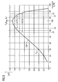
- the corresponding drive function I (d C ) was determined from a number of control points P A at a particular duty cycle, with which the power switch 7 was controlled and thus the motor 6 has been operated or driven.
- the course of the resulting drive function I (d C ) shows a maximum effective ripple current I max of about 1.5 A (per capacitor 2) at a relative duty cycle or duty cycle d c of about 75%.
- a second exclusion region A2 is given to the PWM generator 8, which lies between an upper limit value S3 with d C ⁇ 87.5% and a lower limit value S4 with d C ⁇ 57.5%.
- This comparatively large masked exclusion area A2 is specified to the PWM generator 8 when a second temperature limit value T2 of the operating temperature T C of the capacitor is reached or exceeded.
- the corresponding duty ratio d C is thus set such that exceeding the limit value T1, T2 is reliably avoided.
- the forbidden, excluded or hidden area A1, A2 may possibly be traversed for a short time.
- the excluded or blanked areas A1, A2 can also be set as a function of the capacitor current I E itself and / or of the operating voltage U B. These areas A1, A2 can also be predefined as a function of the ambient temperature. Furthermore, the respective duty cycle d C can be set directly as a function of the ripple current I R , excluding the duty cycle d C assigned to the maximum value I max , in particular with the exclusion of the range A 1, A 2.
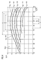
- FIG. 4 shows in a characteristic field, the capacitor current I E at different operating voltages U B , wherein the operating voltage U B increases in the direction of increasing current values from characteristic to characteristic.
- the characteristic curves represent the profile of the respective capacitor current I K in dependence on the PWM generator 8 predetermined relative duty ratio d C.
- the current curves show certain commutation fluctuations, which are caused by the electric motor 6 representing an ohmic inductive load. Recognizable turn are certain duty cycle d c , in which the respective capacitor current I K reaches a maximum I max .
- the respective ripple current amount or value of the capacitor current I K is dependent on the set operating voltage U B.
- the electric motor 6 is a brushless motor, while in the drive characteristic I (d C ) according to FIG. 3 a brush motor is simulated.
- Duty cycle d C Analogous to the embodiment in FIG. 3 can also according to the variant FIG. 4 depending on the set operating voltage U B always above the upper limit value S1 lying Duty cycle d C are set.
- U B 13V
- a duty cycle of d C > 90% can be set.
- a duty cycle of d C ⁇ 80% would not lead to an increased capacitor load here.
- a desired operating condition eg. B. a required fan operation, is not given.
- the corresponding characteristic curves or characteristics fields or the associated control functions I (d C ) are stored for example in an electronic memory of the actuator 5 or a higher-level control device.
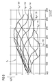
- FIG. 5 shows analogously to FIG. 4 a characteristic field with control functions I (u) at different operating voltages U B , but as a function of the engine speed u [1 / min]. in the Characteristic field are also the control functions I (u) crossing lines of the same duty cycle d C between 70% and 100% deposited. From the maximum value of the respective capacitor current I E arise at a given operating voltage U B for certain engine speeds u turn areas with excluded or forbidden duty cycles d C. According to this characteristic field, only those duty cycles d C are preferably set when driving the circuit breaker 7, which are above a stored first, upper threshold or threshold value S1 of about 90% or below a stored second, lower threshold or threshold value S2 of approx 70% lie.
- the pulse duration t ON related to a clock period t P and the pause duration t OFF and thus the duty cycle d C of the PWM generator 8 are set.
- the respective duty cycle d C is the time t ON the turn-on and the time t OFF of the turn-off of the circuit breaker 7 before.
- the leading to an increased load or even overloading of the capacitor 2 duty cycles d C are avoided. This can be achieved either by their exclusion or by the fact that the corresponding duty cycle d C are set only briefly.
- a corresponding short-term activation of the circuit breaker 7 with a duty cycle d c to be avoided can be effected, for example, by the fact that the PWM generator 8 is driven with this duty ratio d c only with a limited number of clock periods t p. Subsequently, then the control of the PWM generator 8 with a lying outside the predetermined range at duty cycle d C for a number of clock periods t P , the total number of example given by a control unit of a motor duty cycle of the fan and thus the currently required operating time of the engine 6 corresponds.
- a predetermined temperature threshold T1, T2 of the capacitor temperature T C and depending on the respectively set operating voltage U B a certain speed range u avoided during operation of the electric motor 6 or hidden.
- those associated duty cycles d C are hidden, which would lead to a lying in the region of the maximum value capacitor current I K or Ripplestrom I R.
Landscapes
- Engineering & Computer Science (AREA)
- Power Engineering (AREA)
- Control Of Direct Current Motors (AREA)
Claims (5)
- Méthode pour actionner un consommateur électrique (6), en particulier un moteur électrique, auquel est amené un courant de service (IM) produit par une source de tension (4) et stocké par un condensateur (2) par l'intermédiaire d'un élément de réglage (5), qui est commandé avec un taux d'impulsions (de) situé hors de la plage d'exclusion (An), la plage d'exclusion (An) étant définie par une première valeur limite (S1, S3) et une seconde valeur limite (S2, S4) et l'élément de réglage (5) étant commandé à un taux d'impulsions (dc) situé au-delà de la première valeur limite (S1, S3) ou en-deçà de la seconde valeur limite (S2, S4),
le taux d'impulsions (de) étant ajusté à l'aide d'une fonction de commande (I(dc), I(u)) en évitant ou en limitant dans la durée un maximum (PA) de la fonction de commande (I(dc), I(u)) situé dans la plage d'exclusion (An), et
le taux d'impulsions (dc) étant adapté en fonction du courant de condensateur (IK) ou du courant ondulé (IR) du condensateur (2), et
le taux d'impulsions (dc) étant adapté en fonction de la température de service (Tc) du condensateur (2), et
le taux d'impulsions (dc) étant adapté en fonction de la tension de service (UB). - Procédé selon la revendication 1, l'élément de réglage (5) étant commandé avec un taux d'impulsions (dc) inférieur ou égal à 100 et supérieur ou égal à un taux d'impulsions (dc) correspondant à la (première) valeur limite supérieure (S1, S3).
- Système de commande (1) pour un consommateur électrique (6), en particulier pour un moteur électrique, doté d'une source de tension (4) produisant un courant de service (IM) et d'un condensateur (2) ainsi que d'un élément de réglage cadencé (5), qui commande le consommateur (6) à un taux d'impulsions (dc) situé en-dehors d'une plage d'exclusion (Sm, An),
la plage d'exclusion (An) étant définie par une première valeur limite (S1, S3) et une seconde valeur limite (S2, S4) et l'élément de réglage (5) commandant le consommateur (6) à un taux d'impulsions (dc) situé au-delà de la première valeur limite (S1, S3) ou en-deçà de la seconde valeur limite (S2, S4),
le taux d'impulsions (dc) étant ajusté à l'aide d'une fonction de commande (I(dc), I(u)) en évitant ou en limitant dans la durée un maximum (PA) de la fonction de commande (I(dc), I(u)) situé dans la plage d'exclusion (An), et
le taux d'impulsions (dc) étant adapté en fonction du courant de condensateur (IK) ou du courant ondulé (IR) du condensateur (2), et
le taux d'impulsions (dc) étant adapté en fonction de la température de service (Tc) du condensateur (2), et
le taux d'impulsions (dc) étant adapté en fonction de la tension de service (UB). - Système de commande selon la revendication 3, l'élément de réglage (5) comprenant un interrupteur de puissance électronique (7) et un générateur MID (8) commandant ce dernier au taux d'impulsions (de) prédéterminé.
- Système de commande selon la revendication 3 ou 4, dans lequel la durée d'impulsions et de pause (tON, TOFF) du générateur MID (8) se référant à une période d'horloge (tp) est paramétrée en fonction de l'état de service du condensateur (2) de telle sorte que, avec le taux d'impulsions actuel (dc) déterminant la durée temporelle (tON) des cycles de marche et la durée temporelle (tOFF) des cycles d'arrêt de l'interrupteur de puissance (7), une température de service (Tc) du condensateur (2) dépassant une valeur limite (T1, T2) est évitée.
Priority Applications (1)
| Application Number | Priority Date | Filing Date | Title |
|---|---|---|---|
| EP05008664A EP1715574B1 (fr) | 2005-04-20 | 2005-04-20 | Méthode pour actionner un consommateur électrique et un système de commande fonctionnant selon cette méthode |
Applications Claiming Priority (1)
| Application Number | Priority Date | Filing Date | Title |
|---|---|---|---|
| EP05008664A EP1715574B1 (fr) | 2005-04-20 | 2005-04-20 | Méthode pour actionner un consommateur électrique et un système de commande fonctionnant selon cette méthode |
Publications (2)
| Publication Number | Publication Date |
|---|---|
| EP1715574A1 EP1715574A1 (fr) | 2006-10-25 |
| EP1715574B1 true EP1715574B1 (fr) | 2012-08-08 |
Family
ID=34935471
Family Applications (1)
| Application Number | Title | Priority Date | Filing Date |
|---|---|---|---|
| EP05008664A Expired - Fee Related EP1715574B1 (fr) | 2005-04-20 | 2005-04-20 | Méthode pour actionner un consommateur électrique et un système de commande fonctionnant selon cette méthode |
Country Status (1)
| Country | Link |
|---|---|
| EP (1) | EP1715574B1 (fr) |
Families Citing this family (1)
| Publication number | Priority date | Publication date | Assignee | Title |
|---|---|---|---|---|
| DE102012213874A1 (de) | 2012-03-07 | 2013-09-12 | Continental Teves Ag & Co. Ohg | Verfahren und Schaltungsanordnung zur Begrenzung von Spitzenströmen sowie Steigung der Stromflanken |
Citations (1)
| Publication number | Priority date | Publication date | Assignee | Title |
|---|---|---|---|---|
| EP1383232A2 (fr) * | 2002-07-16 | 2004-01-21 | Robert Bosch Gmbh | Méthode d'amélioration de la disponibilité d'un système de ventilateur |
Family Cites Families (3)
| Publication number | Priority date | Publication date | Assignee | Title |
|---|---|---|---|---|
| DE19522045A1 (de) * | 1994-07-12 | 1996-01-18 | Hans Hermann Rottmerhusen | Elektronik für Stromwendermotoren |
| US6864646B2 (en) * | 2003-02-14 | 2005-03-08 | General Motors Corporation | Multiple inverter system with low power bus ripples and method therefor |
| US7016205B2 (en) * | 2003-10-01 | 2006-03-21 | General Electric Company | Ripple-current reduction schemes for AC converters |
-
2005
- 2005-04-20 EP EP05008664A patent/EP1715574B1/fr not_active Expired - Fee Related
Patent Citations (1)
| Publication number | Priority date | Publication date | Assignee | Title |
|---|---|---|---|---|
| EP1383232A2 (fr) * | 2002-07-16 | 2004-01-21 | Robert Bosch Gmbh | Méthode d'amélioration de la disponibilité d'un système de ventilateur |
Also Published As
| Publication number | Publication date |
|---|---|
| EP1715574A1 (fr) | 2006-10-25 |
Similar Documents
| Publication | Publication Date | Title |
|---|---|---|
| EP1715582B1 (fr) | Agencement de circuit destiné à piloter un commutateur de puissance électrique à haute tension | |
| DE3785059T2 (de) | Geschwindigkeitssteuerung fuer ein scheibenwischersystem. | |
| WO2006077069A1 (fr) | Commutation de commande pour moteur a commutation electronique | |
| EP2850725B1 (fr) | Procédé de régulation d'une source de courant, source de courant et régulateur de processus associés | |
| WO2018091145A1 (fr) | Circuit d'attaque | |
| DE112018006822T5 (de) | Leistungsumwandlungsvorrichtung, motormodul und elektrische servolenkvorrichtung | |
| WO2002015374A1 (fr) | Montage et appareil electrique comportant une charge inductive et un convertisseur a inductance | |
| EP1715574B1 (fr) | Méthode pour actionner un consommateur électrique et un système de commande fonctionnant selon cette méthode | |
| EP3748827A1 (fr) | Convertisseur demi-pont avec tension de grille reduite pendant les temps morts | |
| DE4123105A1 (de) | Verfahren und vorrichtung zur regelung der ansteuerleistung elektrischer verbraucher | |
| EP3174204B1 (fr) | Procédé et dispositif de commande d'un élément de commande électrique ou électronique | |
| EP1715573B1 (fr) | Méthode et dispositif pour entrainer des charges électriques | |
| EP3472934A1 (fr) | Circuit à semi-conducteur de puissance | |
| DE102016209630A1 (de) | Verfahren zum Betrieb eines Umrichters sowie Schaltungsanordnung hierfür | |
| EP0551896B1 (fr) | Circuit de freinage pour petits moteurs universels | |
| EP1609236B1 (fr) | Procede et unite de commande pour commander des moteurs ventiles | |
| EP1130760B1 (fr) | Convertisseur de fréquence | |
| DE4311533A1 (de) | Ansteuerschaltung für kollektorlose Gleichstrommotoren | |
| DE10323445B4 (de) | Direkte Umkommutierung zwischen Leistungsbauteilen | |
| DE102021212348B3 (de) | Verfahren zum Ansteuern von Halbleiterschaltern mindestens einer Halbbrücke und Schaltungsanordnung | |
| DE102022201511B4 (de) | Verfahren zur Ansteuerung von Leistungshalbleitern eines Inverters, Computerprogramm, Vorrichtung zur Datenverarbeitung, Inverter, Elektroantrieb sowie Fahrzeug | |
| EP2504917B1 (fr) | Dispositif et procédé pour mesurer un courant de moteur d'un moteur à courant continu | |
| DE102004017401A1 (de) | Schaltungsanordnung und Verfahren zur Kurzschlussbremsung eines Gleichstrommotors | |
| DE102020214810B3 (de) | Verfahren zum Betreiben eines Gleichstrommotors | |
| EP2625420A1 (fr) | Procédé pour faire fonctionner une machine électrique |
Legal Events
| Date | Code | Title | Description |
|---|---|---|---|
| PUAI | Public reference made under article 153(3) epc to a published international application that has entered the european phase |
Free format text: ORIGINAL CODE: 0009012 |
|
| AK | Designated contracting states |
Kind code of ref document: A1 Designated state(s): AT BE BG CH CY CZ DE DK EE ES FI FR GB GR HU IE IS IT LI LT LU MC NL PL PT RO SE SI SK TR |
|
| AX | Request for extension of the european patent |
Extension state: AL BA HR LV MK YU |
|
| 17P | Request for examination filed |
Effective date: 20061120 |
|
| AKX | Designation fees paid |
Designated state(s): DE FR |
|
| RAP1 | Party data changed (applicant data changed or rights of an application transferred) |
Owner name: BROSE FAHRZEUGTEILE GMBH & CO. KG |
|
| RAP1 | Party data changed (applicant data changed or rights of an application transferred) |
Owner name: BROSE FAHRZEUGTEILE GMBH & CO. KG, WUERZBURG |
|
| 17Q | First examination report despatched |
Effective date: 20091029 |
|
| GRAP | Despatch of communication of intention to grant a patent |
Free format text: ORIGINAL CODE: EPIDOSNIGR1 |
|
| RIC1 | Information provided on ipc code assigned before grant |
Ipc: H02M 1/12 20060101ALI20120221BHEP Ipc: H02P 7/29 20060101AFI20120221BHEP |
|
| GRAS | Grant fee paid |
Free format text: ORIGINAL CODE: EPIDOSNIGR3 |
|
| GRAA | (expected) grant |
Free format text: ORIGINAL CODE: 0009210 |
|
| AK | Designated contracting states |
Kind code of ref document: B1 Designated state(s): DE FR |
|
| REG | Reference to a national code |
Ref country code: DE Ref legal event code: R096 Ref document number: 502005012972 Country of ref document: DE Effective date: 20121011 |
|
| PLBE | No opposition filed within time limit |
Free format text: ORIGINAL CODE: 0009261 |
|
| STAA | Information on the status of an ep patent application or granted ep patent |
Free format text: STATUS: NO OPPOSITION FILED WITHIN TIME LIMIT |
|
| 26N | No opposition filed |
Effective date: 20130510 |
|
| REG | Reference to a national code |
Ref country code: DE Ref legal event code: R097 Ref document number: 502005012972 Country of ref document: DE Effective date: 20130510 |
|
| PG25 | Lapsed in a contracting state [announced via postgrant information from national office to epo] |
Ref country code: DE Free format text: LAPSE BECAUSE OF NON-PAYMENT OF DUE FEES Effective date: 20131101 |
|
| REG | Reference to a national code |
Ref country code: FR Ref legal event code: ST Effective date: 20131231 |
|
| REG | Reference to a national code |
Ref country code: DE Ref legal event code: R119 Ref document number: 502005012972 Country of ref document: DE Effective date: 20131101 |
|
| PG25 | Lapsed in a contracting state [announced via postgrant information from national office to epo] |
Ref country code: FR Free format text: LAPSE BECAUSE OF NON-PAYMENT OF DUE FEES Effective date: 20130430 |