EP1715217A2 - Mechanical chain tensioner with ratcheting device - Google Patents
Mechanical chain tensioner with ratcheting device Download PDFInfo
- Publication number
- EP1715217A2 EP1715217A2 EP06005608A EP06005608A EP1715217A2 EP 1715217 A2 EP1715217 A2 EP 1715217A2 EP 06005608 A EP06005608 A EP 06005608A EP 06005608 A EP06005608 A EP 06005608A EP 1715217 A2 EP1715217 A2 EP 1715217A2
- Authority
- EP
- European Patent Office
- Prior art keywords
- tensioner
- sliding surface
- spring clip
- blade
- distal end
- Prior art date
- Legal status (The legal status is an assumption and is not a legal conclusion. Google has not performed a legal analysis and makes no representation as to the accuracy of the status listed.)
- Granted
Links
Images


Classifications
-
- F—MECHANICAL ENGINEERING; LIGHTING; HEATING; WEAPONS; BLASTING
- F16—ENGINEERING ELEMENTS AND UNITS; GENERAL MEASURES FOR PRODUCING AND MAINTAINING EFFECTIVE FUNCTIONING OF MACHINES OR INSTALLATIONS; THERMAL INSULATION IN GENERAL
- F16H—GEARING
- F16H7/00—Gearings for conveying rotary motion by endless flexible members
- F16H7/08—Means for varying tension of belts, ropes, or chains
- F16H7/0848—Means for varying tension of belts, ropes, or chains with means for impeding reverse motion
-
- F—MECHANICAL ENGINEERING; LIGHTING; HEATING; WEAPONS; BLASTING
- F16—ENGINEERING ELEMENTS AND UNITS; GENERAL MEASURES FOR PRODUCING AND MAINTAINING EFFECTIVE FUNCTIONING OF MACHINES OR INSTALLATIONS; THERMAL INSULATION IN GENERAL
- F16H—GEARING
- F16H7/00—Gearings for conveying rotary motion by endless flexible members
- F16H7/08—Means for varying tension of belts, ropes, or chains
- F16H2007/0802—Actuators for final output members
- F16H2007/0804—Leaf springs
-
- F—MECHANICAL ENGINEERING; LIGHTING; HEATING; WEAPONS; BLASTING
- F16—ENGINEERING ELEMENTS AND UNITS; GENERAL MEASURES FOR PRODUCING AND MAINTAINING EFFECTIVE FUNCTIONING OF MACHINES OR INSTALLATIONS; THERMAL INSULATION IN GENERAL
- F16H—GEARING
- F16H7/00—Gearings for conveying rotary motion by endless flexible members
- F16H7/08—Means for varying tension of belts, ropes, or chains
- F16H7/0848—Means for varying tension of belts, ropes, or chains with means for impeding reverse motion
- F16H2007/0853—Ratchets
-
- F—MECHANICAL ENGINEERING; LIGHTING; HEATING; WEAPONS; BLASTING
- F16—ENGINEERING ELEMENTS AND UNITS; GENERAL MEASURES FOR PRODUCING AND MAINTAINING EFFECTIVE FUNCTIONING OF MACHINES OR INSTALLATIONS; THERMAL INSULATION IN GENERAL
- F16H—GEARING
- F16H7/00—Gearings for conveying rotary motion by endless flexible members
- F16H7/08—Means for varying tension of belts, ropes, or chains
- F16H2007/0876—Control or adjustment of actuators
- F16H2007/0878—Disabling during transport
Definitions
- the invention pertains to the field of tensioners. More particularly, the invention pertains to a tensioner with a ratcheting device.
- Blade tensioners are commonly used to control a chain or belt where load fluctuations are not so severe as to over flex the spring or springs.
- a ratchet with backlash is added to tensioners to limit the effective backward or untensioned travel of a tensioning device.
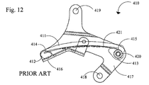
- Prior art Figure 12 shows an example of a blade tensioner.
- the conventional blade tensioner 410 includes a blade shoe 411 made of resin having a curved chain sliding face and numerous blade springs 421, preferably made of metallic material.
- the blade springs 421 are arranged in layers on the opposite side of the blade shoe 411 from the chain sliding face, and provide spring force to the blade shoe 411.
- the ends of each spring-shaped blade spring 421 are inserted in the indented portions 414 and 415, which are formed in the distal portion 412 and proximal portion 413 of the blade shoe 411, respectively.
- a bracket 417 is provided for mounting the blade tensioner 410 in an engine. Holes 418 and 419 are formed in the bracket 417, and mounting bolts are inserted into these holes 418 and 419.
- a sliding face 416 contacts the distal portion of the blade shoe 411 and permits sliding. The slide face 416 is formed on the distal portion of the bracket 417.
- a pin 420 supports the proximal portion 413 of the blade shoe 411 so that it may move in either direction. The pin 420 is secured on the bracket 417.
- the ratchet tensioner 301 comprises a tensioner housing 307 having a hole 312 for receiving a plunger 308 and a ratchet pawl 317 pivoted by a shaft 316 to the tensioner housing 307 and biased by a ratchet spring 318.
- the plunger 308 has teeth on one outer side that engage the ratchet pawl 317.
- the plunger 308 is biased out of the hole 312 to contact the tension lever 310 by fluid in the hollow section 313 and by the plunger spring 314.
- the tensioner lever 310 pivots on support shaft 309 and has a shoe surface 311 that contacts and applies tension to the slack side of the timing chain 306 wrapped around the camshaft 304 and its sprocket 305 and the crankshaft 302 and its sprocket 303.
- the plunger's 308 movement in and out of the hole 312 is limited by its teeth and the ratchet pawl 317 that engage them.
- Prior art Figure 10 shows a prior art blade tensioner with a bracket of US 6,238,311 , which is hereby incorporated by reference.
- a bracket 115 has a blade tensioner 100 attached on one side and on an opposite side from the blade tensioner a passive snubber 188 is attached to guide the chain (not shown).
- the blade tensioner 100 is comprised of a blade shoe 130 with a first end 142 and a second end 140.
- the first end 142 is attached to the bracket 115 by a pivot pin 190.
- a blade spring end is placed within the first end 142 and the second end 140 of the blade shoe 130 and pushes against the length of the blade shoe, causing it to bow slightly towards the chain.
- the second end 122 of the blade spring is secured to the blade shoe 130 by hollow roll pin 150.
- the blade spring causes the shoe to bow slightly. As the shoe heats up, the shoe bows even more until the chain prevents further bowing.
- Part of the bracket 115, adjacent to the second end of the shoe 140 is formed into a tab 135.
- the tab 135 is spaced outward from the bracket face and has a notch 145 aligned with the roll pin 150.
- the first end 142 of the blade shoe 130 pivots on pin 190.
- the blade shoe is kept on pin 190 by tab 135.
- Prior art Figure 11 shows a tensioner that uses a ratchet device.
- the tensioner includes a housing 270 having a bore 220 that receives a pair of pawls 250, 252 held in place by circlip 260.
- a piston 202 with grooves 211, is slidably received within bore 220 and is biased in a protruding direction from the bore 220 by spring 204. As the piston 202 moves in a protruding direction from the bore 220, the grooves 211 of the piston engage the teeth of pawls 250, 252.
- a blade tensioner that imparts tension to a chain that drivingly connects a driven shaft to a driving shaft in an engine.
- the blade tensioner has a blade shoe with an accurately curved chain sliding face, a proximal end pivotally attached to a pivot pin of a bracket and a distal end that receives a ratchet rod.
- the distal end of the blade shoe slides along a first side of a sliding surface, which may be part of the bracket.
- the ratchet rod has a first end pivotally attached to the distal end of the shoe and a second end with a length having a plurality of teeth having a length.
- a spring clip receives the second end of the ratchet rod and has an edge for abutting or engaging the teeth of the ratchet rod.
- the spring clip biases the ratchet rod on the side opposite the length having a plurality of teeth so that the teeth of the ratchet rod engage with the edge of the spring clip.
- the spring clip is slidable along the second side of the sliding surface until the tab on the spring clip engages with a corresponding indentation on the second side of the sliding surface.
- the distal end of the blade shoe pivots away from the chain and slides on the first side of the sliding surface, forcing the ratchet rod toward the pivot pin.
- the toothed ramp of the ratchet rod is in contact with the edge of the spring clip and drags the spring clip on the second side of the sliding surface of the bracket along, until the spring clip tab mates with a corresponding indentation in the bracket.
- the slack of the chain may allow continued movement of the distal end of the blade shoe, ratcheting other teeth on the ratchet rod over the engaged edge of the spring clip.
- Figure 1 shows a schematic of the tensioner 501 with a chain 500.
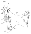
- Figures 2a and 2b show the tensioner 501 and bracket 502 without the chain.
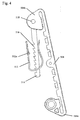
- Figure 3 shows just the bracket 502.
- the tensioner 501 and guide 520 are attached to the bracket 502.
- the tensioner is comprised of a blade shoe 504 having an arcuately curved chain sliding face 504c, a distal end 504b, and a proximal end 504a.
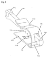
- the distal end 504b of the tensioner is bifurcated as shown in Figure 5 and receives a first end 514a of ratchet rod 514 and pin 518.
- the proximal end of the blade shoe pivots on pivot pin 510 of bracket 502.
- a blade spring 506 is placed between the blade shoe 504 and the bracket 502.
- the blade spring 506 runs along the length of the blade shoe (e.g. from the distal end to the proximal end).
- the blade spring 506 may consist of a single blade spring or multiple blade springs.
- the bracket 502 has a guide side 502c and an opposing tensioner side 502b.
- Tab 502a, spaced away from the bracket faces is integral to the tensioner side 502b of the bracket 502 is bent up away from the bracket and towards the center of the bracket 502.
- the distal end 504b of the blade shoe 504 fits between the tab 502a and the bracket face.
- Tab 502a prevents the proximal end 504a of the blade shoe 504 from disengaging pivot pin 510 of bracket 502.
- the distal end 504b of the blade shoe 504 slides on the inner ramp surface 502d of bent portion of the bracket 502 that forms tab 502a of the bracket 502.
- the outer surface 502e of the bent portion of the bracket 502 that forms tab 502a receives a spring clip 512, preferably U-shaped. Also located on the tensioner side 502b of the bracket is pivot pin 510, which the proximal end 504a of the blade shoe 504 pivots.
- the guide 520 is preferably stationary and fixedly attached to the guide side 502c of bracket 502 and aids in maintaining chain placement with respect to the blade shoe 504 on the opposite side of the bracket 502.
- a ratchet rod 514 Pivotally attached to the bifurcated distal end 504b of the blade shoe 504 by pin 518 is a ratchet rod 514 with a first end 514a for receiving pin 518 and a second end 514b with ratchet teeth 516 along its length on at least one side as shown in Figures 4 and 7.
- the U-shaped spring clip 512 slides onto and receives the outer portion 502e of the bent portion of the bracket 502 that forms tab 502a and the ratchet teethed second end 514b of the ratchet rod 514.
- the bottom 512e of the U-shaped spring clip 512 joins the straight side 512c of the spring clip 512 with the curved side 512d of the spring clip as shown in Figure 6 and 8.
- the curved side 512d of the U-shaped spring clip 512 applies a spring force on a portion of the ratchet rod 514 that does not have the ratchet teeth 516, forcing the ratchet teeth 516 on the other side of the ratchet rod 514 to engage or act as a ratchet with the edge of the opening 512b at the bottom 512e of the U-shaped spring clip 512.
- the spring force applied to the ratchet rod 514 by the curved side 512d of the spring clip 512 causes the edge of opening 512b at the bottom 512e of the U-shaped spring clip 512 to be forcefully engaged with the teeth 516 of ratchet rod 514.
- the resulting friction plus the angle of ramp 516a of teeth 516 in contact with edge 512b of the clip moves spring clip 512 in the direction of arrow 550, to the limit allowed by the forced engagement of tab 512a with the edge of the indentation in the outer portion 502e of the bracket.
- the distance between the bottom 512e of spring clip 512 and the pivot pin end of inner ramp surface 502d of bracket 502 determines one element of backlash of the tensioner. Additional movement of the distal end portion of the blade shoe 504 and companion ratchet rod 514 in the direction of arrow 550 would cause sliding between ramp 516a of the ratchet rod teeth 516 and the spring clip edge 512b ratcheting from tooth to tooth 516. Tooth length is the determinate of the second element of backlash of the tensioner. Backlash is the sum of the two elements and is the functional limit of the movement allowed in the direction opposite of arrow 550.
- the spring force applied to the ratchet rod 514 by the curved side 512d of the spring clip 512 causes the edge of the opening 512b at the bottom of the U-shaped clip to engage with the teeth 516 on the ratchet rod 514.
- the distal end portion 504b will continue to move towards the pivot pin 510, shown by arrow 550, as long as increased chain length due to chain wear continues to provide slack.
- the length of the ratchet rod 514, the number of teeth 516, and the location of spring clip 512 as related to arrow 550 depend on the intended wear life of the chain and how the related wear caused length growth effects the position of the distal end of the blade shoe 504b in sliding contact with ramp surface 502d of the bracket 502.
- the force of the chain 500 compresses the blade shoe 504, and the distal end portion 504b of the blade shoe 504 slides on the inner ramp surface 502d of the bent portion of the bracket 502 and away form the pivot pin 510 in a direction opposite of arrow 550.
- the spring clip 512 moves a distance up the outer surface 502e of the bent portion of bracket 502 until the bottom 512e of U-shaped clip 512 abuts with the end of surface 502e and stops.
- Ratchet 514 continues to move with the blade shoe, by tooth 516 sliding in engagement with edge of opening 512b at the bottom 512e of U-shaped clip 512 until the blunt edge of tooth 516 at the end of ramp 516a abuts the bottom 512e and is stopped. This limited motion is the backlash.
- Pin 508 is present to maintain the tensioner in a fixed shipping/installation position.
- the function of the bracket 502 may be achieved by protrusions on the engine block.
Abstract
Description
- The invention pertains to the field of tensioners. More particularly, the invention pertains to a tensioner with a ratcheting device.
- Blade tensioners are commonly used to control a chain or belt where load fluctuations are not so severe as to over flex the spring or springs. A ratchet with backlash is added to tensioners to limit the effective backward or untensioned travel of a tensioning device.
- Prior art Figure 12 shows an example of a blade tensioner. The
conventional blade tensioner 410 includes ablade shoe 411 made of resin having a curved chain sliding face andnumerous blade springs 421, preferably made of metallic material. Theblade springs 421 are arranged in layers on the opposite side of theblade shoe 411 from the chain sliding face, and provide spring force to theblade shoe 411. The ends of each spring-shaped blade spring 421 are inserted in theindented portions distal portion 412 andproximal portion 413 of theblade shoe 411, respectively. - A
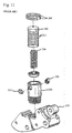
bracket 417 is provided for mounting theblade tensioner 410 in an engine.Holes bracket 417, and mounting bolts are inserted into theseholes face 416 contacts the distal portion of theblade shoe 411 and permits sliding. Theslide face 416 is formed on the distal portion of thebracket 417. Apin 420 supports theproximal portion 413 of theblade shoe 411 so that it may move in either direction. Thepin 420 is secured on thebracket 417. - One example of a tensioner that uses a ratchet device is shown in prior art Figure 9. The
ratchet tensioner 301 comprises atensioner housing 307 having ahole 312 for receiving aplunger 308 and aratchet pawl 317 pivoted by ashaft 316 to thetensioner housing 307 and biased by aratchet spring 318. Theplunger 308 has teeth on one outer side that engage theratchet pawl 317. Theplunger 308 is biased out of thehole 312 to contact thetension lever 310 by fluid in thehollow section 313 and by theplunger spring 314. The tensioner lever 310 pivots onsupport shaft 309 and has ashoe surface 311 that contacts and applies tension to the slack side of thetiming chain 306 wrapped around thecamshaft 304 and itssprocket 305 and thecrankshaft 302 and itssprocket 303. The plunger's 308 movement in and out of thehole 312 is limited by its teeth and theratchet pawl 317 that engage them. - Prior art Figure 10 shows a prior art blade tensioner with a bracket of
US 6,238,311 , which is hereby incorporated by reference. Abracket 115 has ablade tensioner 100 attached on one side and on an opposite side from the blade tensioner apassive snubber 188 is attached to guide the chain (not shown). Theblade tensioner 100 is comprised of ablade shoe 130 with afirst end 142 and asecond end 140. Thefirst end 142 is attached to thebracket 115 by apivot pin 190. A blade spring end is placed within thefirst end 142 and thesecond end 140 of theblade shoe 130 and pushes against the length of the blade shoe, causing it to bow slightly towards the chain. Thesecond end 122 of the blade spring is secured to theblade shoe 130 byhollow roll pin 150. The blade spring causes the shoe to bow slightly. As the shoe heats up, the shoe bows even more until the chain prevents further bowing. Part of thebracket 115, adjacent to the second end of theshoe 140 is formed into atab 135. Thetab 135 is spaced outward from the bracket face and has anotch 145 aligned with theroll pin 150. Thefirst end 142 of theblade shoe 130 pivots onpin 190. The blade shoe is kept onpin 190 bytab 135. When theretaining pin 155 is placed in theroll pin 150, the blade tensioner is held in a retracted position for shipping. - Prior art Figure 11 shows a tensioner that uses a ratchet device. The tensioner includes a
housing 270 having abore 220 that receives a pair ofpawls circlip 260. Apiston 202, withgrooves 211, is slidably received withinbore 220 and is biased in a protruding direction from thebore 220 byspring 204. As thepiston 202 moves in a protruding direction from thebore 220, thegrooves 211 of the piston engage the teeth ofpawls - The prior art does not show an adequate means of adding a ratchet device to a blade tensioner.
- A blade tensioner that imparts tension to a chain that drivingly connects a driven shaft to a driving shaft in an engine. The blade tensioner has a blade shoe with an accurately curved chain sliding face, a proximal end pivotally attached to a pivot pin of a bracket and a distal end that receives a ratchet rod. The distal end of the blade shoe slides along a first side of a sliding surface, which may be part of the bracket. The ratchet rod has a first end pivotally attached to the distal end of the shoe and a second end with a length having a plurality of teeth having a length. A spring clip receives the second end of the ratchet rod and has an edge for abutting or engaging the teeth of the ratchet rod. The spring clip biases the ratchet rod on the side opposite the length having a plurality of teeth so that the teeth of the ratchet rod engage with the edge of the spring clip. The spring clip is slidable along the second side of the sliding surface until the tab on the spring clip engages with a corresponding indentation on the second side of the sliding surface.
- When the slack of the chain increases, the distal end of the blade shoe pivots away from the chain and slides on the first side of the sliding surface, forcing the ratchet rod toward the pivot pin. The toothed ramp of the ratchet rod is in contact with the edge of the spring clip and drags the spring clip on the second side of the sliding surface of the bracket along, until the spring clip tab mates with a corresponding indentation in the bracket. The slack of the chain may allow continued movement of the distal end of the blade shoe, ratcheting other teeth on the ratchet rod over the engaged edge of the spring clip.
- Movement in the opposite direction is denied except for the intended backlash of the teeth of the ratchet rod as they abut the edge of the spring clip. Backlash is the allowed shuttle movement of the spring clip plus the length of one tooth of the plurality of teeth on the ratchet rod.
-
- Fig. 1 shows a schematic of the tensioner of the present invention with a chain.
- Fig. 2a shows a front view of the tensioner of the present invention without a chain. Fig. 2b shows an alternate view of the tensioner of the present invention without a chain.
- Fig. 3 shows a front view of the bracket of the tensioner.
- Fig. 4 shows the blade shoe of the tensioner with the ratchet device and clip.
- Fig. 5 shows a side view of the blade shoe of the tensioner.
- Fig. 6 shows a view of the clip.
- Fig. 7 shows the ratchet rod with ratchet teeth.
- Fig. 8 shows the interaction between the U-shaped clip and the teeth of the ratchet rod.
- Fig. 9 shows a prior art ratcheting tensioner and chain.
- Fig. 10 shows a prior art blade tensioner and bracket.
- Fig. 11 shows a prior art tensioner with a ratcheting device.
- Fig. 12 shows another prior art blade tensioner and bracket.
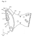
- Fig. 13 shows a schematic of the tensioner of the present invention when the slack in the chain increases.
- Figure 1 shows a schematic of the
tensioner 501 with achain 500. Figures 2a and 2b show thetensioner 501 andbracket 502 without the chain. Figure 3 shows just thebracket 502. - The
tensioner 501 and guide 520 are attached to thebracket 502. Referring to Figures 2a and 2b, the tensioner is comprised of ablade shoe 504 having an arcuately curvedchain sliding face 504c, adistal end 504b, and aproximal end 504a. Thedistal end 504b of the tensioner is bifurcated as shown in Figure 5 and receives afirst end 514a ofratchet rod 514 andpin 518. The proximal end of the blade shoe pivots onpivot pin 510 ofbracket 502. Ablade spring 506 is placed between theblade shoe 504 and thebracket 502. Theblade spring 506 runs along the length of the blade shoe (e.g. from the distal end to the proximal end). Theblade spring 506 may consist of a single blade spring or multiple blade springs. - Referring to Figure 3, the
bracket 502 has aguide side 502c and an opposingtensioner side 502b.Tab 502a, spaced away from the bracket faces is integral to thetensioner side 502b of thebracket 502 is bent up away from the bracket and towards the center of thebracket 502. Thedistal end 504b of theblade shoe 504 fits between thetab 502a and the bracket face.Tab 502a prevents theproximal end 504a of theblade shoe 504 from disengagingpivot pin 510 ofbracket 502. Thedistal end 504b of theblade shoe 504 slides on theinner ramp surface 502d of bent portion of thebracket 502 that formstab 502a of thebracket 502. Theouter surface 502e of the bent portion of thebracket 502 that formstab 502a receives aspring clip 512, preferably U-shaped. Also located on thetensioner side 502b of the bracket ispivot pin 510, which theproximal end 504a of theblade shoe 504 pivots. Theguide 520 is preferably stationary and fixedly attached to theguide side 502c ofbracket 502 and aids in maintaining chain placement with respect to theblade shoe 504 on the opposite side of thebracket 502. - Pivotally attached to the bifurcated
distal end 504b of theblade shoe 504 bypin 518 is aratchet rod 514 with afirst end 514a for receivingpin 518 and asecond end 514b withratchet teeth 516 along its length on at least one side as shown in Figures 4 and 7. TheU-shaped spring clip 512 slides onto and receives theouter portion 502e of the bent portion of thebracket 502 that formstab 502a and the ratchet teethedsecond end 514b of theratchet rod 514. The bottom 512e of theU-shaped spring clip 512 joins thestraight side 512c of thespring clip 512 with thecurved side 512d of the spring clip as shown in Figure 6 and 8. Thecurved side 512d of theU-shaped spring clip 512 applies a spring force on a portion of theratchet rod 514 that does not have theratchet teeth 516, forcing theratchet teeth 516 on the other side of theratchet rod 514 to engage or act as a ratchet with the edge of theopening 512b at the bottom 512e of theU-shaped spring clip 512. - More specifically, as the
distal end portion 504b of theblade shoe 504 moves towards thepivot pin 510, the spring force applied to theratchet rod 514 by thecurved side 512d of thespring clip 512 causes the edge of opening 512b at the bottom 512e of theU-shaped spring clip 512 to be forcefully engaged with theteeth 516 ofratchet rod 514. The resulting friction plus the angle oframp 516a ofteeth 516 in contact withedge 512b of the clip movesspring clip 512 in the direction ofarrow 550, to the limit allowed by the forced engagement oftab 512a with the edge of the indentation in theouter portion 502e of the bracket. The distance between the bottom 512e ofspring clip 512 and the pivot pin end ofinner ramp surface 502d ofbracket 502 determines one element of backlash of the tensioner. Additional movement of the distal end portion of theblade shoe 504 andcompanion ratchet rod 514 in the direction ofarrow 550 would cause sliding betweenramp 516a of theratchet rod teeth 516 and thespring clip edge 512b ratcheting from tooth totooth 516. Tooth length is the determinate of the second element of backlash of the tensioner. Backlash is the sum of the two elements and is the functional limit of the movement allowed in the direction opposite ofarrow 550. - When the slack in the
chain 500 increases, or the tension in the chain decreases, as shown in Figure 13, thedistal end portion 504b of theblade shoe 504 slides oninner ramp surface 502d of bent portion of thebracket 502, towards thepivot pin 510 shown byarrow 550, causing theblade shoe 504 to slightly bow out towards the chain 500 (not shown) and thus tension thechain 500. As thedistal end portion 504b slides on theinner ramp surface 502d of thebracket 502, thespring clip 512 moves to the limit allowed bysecured tab 502a forcefully engaged in the indentation in theouter portion 502e ofbracket 502 for preventing theU-shaped clip 512 from sliding further down and off of thebracket 502. As stated above, the spring force applied to theratchet rod 514 by thecurved side 512d of thespring clip 512 causes the edge of theopening 512b at the bottom of the U-shaped clip to engage with theteeth 516 on theratchet rod 514. Thedistal end portion 504b will continue to move towards thepivot pin 510, shown byarrow 550, as long as increased chain length due to chain wear continues to provide slack. The length of theratchet rod 514, the number ofteeth 516, and the location ofspring clip 512 as related toarrow 550 depend on the intended wear life of the chain and how the related wear caused length growth effects the position of the distal end of theblade shoe 504b in sliding contact withramp surface 502d of thebracket 502. - When the slack on the
chain 500 decreases or the load on the chain increases, the force of thechain 500 compresses theblade shoe 504, and thedistal end portion 504b of theblade shoe 504 slides on theinner ramp surface 502d of the bent portion of thebracket 502 and away form thepivot pin 510 in a direction opposite ofarrow 550. As thedistal end portion 504b slides on theinner ramp surface 502d ofbracket 502, thespring clip 512 moves a distance up theouter surface 502e of the bent portion ofbracket 502 until the bottom 512e ofU-shaped clip 512 abuts with the end ofsurface 502e and stops.Ratchet 514, however, continues to move with the blade shoe, bytooth 516 sliding in engagement with edge of opening 512b at the bottom 512e ofU-shaped clip 512 until the blunt edge oftooth 516 at the end oframp 516a abuts the bottom 512e and is stopped. This limited motion is the backlash. -
Pin 508 is present to maintain the tensioner in a fixed shipping/installation position. - While a
spring clip 512 that is U-shaped is the preferred shape for the clip, other shapes performing the same functions may also be used. - The function of the
bracket 502 may be achieved by protrusions on the engine block. - Accordingly, it is to be understood that the embodiments of the invention herein described are merely illustrative of the application of the principles of the invention. Reference herein to details of the illustrated embodiments is not intended to limit the scope of the claims, which themselves recite those features regarded as essential to the invention.
Claims (18)
- A blade tensioner system for a chain, the system including a blade tensioner imparting tension to the chain that drivingly connects a driven shaft to a driving shaft in an engine, the blade tensioner comprising:a blade shoe having an arcuately curved chain sliding face, a proximal end portion pivotally attached to a bracket and a distal end portion;a sliding surface having a first side for slidably receiving the distal end portion of the blade shoe and a second side;a ratchet rod having a first end pivotally attached to the distal end of the blade shoe and a second end with a length having a plurality of teeth with a length; anda spring clip for receiving the second end of the ratchet rod and being slidable along the second side of the sliding surface, the spring clip having: an edge for abutting the plurality of teeth of the ratchet rod and pressing against the ratchet rod opposite the length of the rod having the plurality of teeth, to bias the ratchet rod into engagement with the edge of the spring clip and a tab for engagement with a corresponding indentation on the second side of the sliding surface;wherein when slack of the chain increases, the distal end of the blade shoe pivots away from the chain and slides on the first side of the sliding surface, and the spring clip slides on the second side of the sliding surface a distance limited by the engagement of the tab of the spring clip with the corresponding indentation on the second side of the sliding surface, such that the edge of the spring clip abuts the plurality of teeth of the ratchet rod, allowing movement of the distal end of the blade shoe towards the proximal end of the blade shoe and preventing movement in an opposite direction.
- The tensioner of claim 1, wherein the distal end of the blade shoe is bifurcated.
- The tensioner of claim 1, wherein the bracket is an engine block.
- The tensioner of claim 1, wherein the bracket further comprising a snubber attached opposite the sliding surface for receiving the distal end portion of the blade shoe.
- The tensioner of claim 1, wherein the bracket further comprises an integral tab for maintaining the blade shoe pivotally attached to the bracket.
- The tensioner of claim 1, wherein the sliding surface for receiving the distal end portion of the blade shoe is on the bracket.
- The tensioner of claim 1, wherein the sliding surface for receiving the distal end portion of the blade shoe is on the engine block.
- The tensioner of claim 1, wherein the spring clip is U-shaped and has a straight side and a curved side connected by a curved bottom defining a hole with the edge for abutting the plurality of teeth of the ratchet rod.
- The tensioner of claim 8, wherein the straight side of the spring clip has the tab for engagement with a corresponding indentation on the second side of the sliding surface.
- The tensioner of claim 1, wherein maximum backlash of the tensioner is a sum of a distance between the edge of the spring clip and a bottom of the first sliding surface and the length of the teeth of the ratchet rod.
- A blade tensioner system for a chain, the system including a blade tensioner imparting tension to the chain that drivingly connects a driven shaft to a driving shaft in an engine, the blade tensioner comprising:a blade shoe having an arcuately curved chain sliding face, a proximal end portion pivotally attached to a bracket and a distal end portion;a sliding surface having a first side for slidably receiving the distal end portion of the blade shoe and a second side;a ratchet rod having a first end pivotally attached to the distal end of the blade shoe and a second end with a length having a plurality of teeth with a length; anda spring clip for receiving the second end of the ratchet rod and being slidable along the second side of the sliding surface, the spring clip having: an edge for abutting the plurality of teeth of the ratchet rod and pressing against the ratchet rod opposite the length of the rod having the plurality of teeth, to bias the ratchet rod into engagement with the edge of the spring clip and a tab for engagement with a corresponding indentation on the second side of the sliding surface;wherein when slack of the chain increases, the distal end of the blade shoe pivots away from the chain and slides on the first side of the sliding surface, and the spring clip slides on the second side of the sliding surface a distance limited by the engagement of the tab of the spring clip with the corresponding indentation on the second side of the sliding surface, such that the edge of the spring clip abuts the plurality of teeth of the ratchet rod, allowing movement of the distal end of the blade shoe towards the proximal end of the blade shoe and preventing movement in an opposite direction;wherein maximum backlash of the tensioner is a sum of a distance between the edge of the spring clip and a bottom of the first sliding surface and the length of the teeth of the ratchet rod.
- The tensioner of claim 11, wherein the distal end of the blade shoe is bifurcated.
- The tensioner of claim 11, wherein the bracket is an engine block.
- The tensioner of claim 11, wherein the bracket further comprising a snubber attached opposite the sliding surface for receiving the distal end portion of the blade shoe.
- The tensioner of claim 11, wherein the sliding surface for receiving the distal end portion of the blade shoe is on the bracket.
- The tensioner of claim 11, wherein the sliding surface for receiving the distal end portion of the blade shoe is on the engine block.
- The tensioner of claim 11, wherein the spring clip is U-shaped and has a straight side and a curved side connected by a curved bottom defining a hole with the edge for abutting the plurality of teeth of the ratchet rod..
- The tensioner of claim 17, wherein the straight side of the spring clip has the tab for engagement with a corresponding indentation on the second side of the sliding surface.
Applications Claiming Priority (1)
| Application Number | Priority Date | Filing Date | Title |
|---|---|---|---|
| US11/108,449 US7513843B2 (en) | 2005-04-18 | 2005-04-18 | Mechanical chain tensioner with ratcheting device |
Publications (3)
| Publication Number | Publication Date |
|---|---|
| EP1715217A2 true EP1715217A2 (en) | 2006-10-25 |
| EP1715217A3 EP1715217A3 (en) | 2008-02-06 |
| EP1715217B1 EP1715217B1 (en) | 2009-09-02 |
Family
ID=36676008
Family Applications (1)
| Application Number | Title | Priority Date | Filing Date |
|---|---|---|---|
| EP06005608A Expired - Fee Related EP1715217B1 (en) | 2005-04-18 | 2006-03-20 | Mechanical chain tensioner with ratcheting device |
Country Status (4)
| Country | Link |
|---|---|
| US (1) | US7513843B2 (en) |
| EP (1) | EP1715217B1 (en) |
| JP (1) | JP4815234B2 (en) |
| DE (1) | DE602006008855D1 (en) |
Cited By (3)
| Publication number | Priority date | Publication date | Assignee | Title |
|---|---|---|---|---|
| EP2166197A1 (en) * | 2008-09-22 | 2010-03-24 | Kunststoff Schwanden AG | Chain drive for camshafts |
| WO2013013839A1 (en) * | 2011-07-22 | 2013-01-31 | Schaeffler Technologies AG & Co. KG | Clamping device |
| US9394976B2 (en) | 2013-06-07 | 2016-07-19 | Schaeffler Technologies AG & Co. KG | Hydraulically ratcheted chain tensioner |
Families Citing this family (17)
| Publication number | Priority date | Publication date | Assignee | Title |
|---|---|---|---|---|
| JP5221388B2 (en) * | 2006-02-07 | 2013-06-26 | ボーグワーナー インコーポレーテッド | Self-intensifying brake for tensioners |
| JP5226665B2 (en) * | 2006-04-20 | 2013-07-03 | ボーグワーナー インコーポレーテッド | Ratchet mechanism for chain drive |
| DE202006012966U1 (en) * | 2006-08-23 | 2007-12-27 | JOH. WINKLHOFER & SÖHNE GMBH & Co. KG | Clamping rail for a chain drive with a bridging guide channel section as pressing area |
| KR101407456B1 (en) * | 2006-10-25 | 2014-06-16 | 보르그워너 인코퍼레이티드 | Pivot arm tensioner with sliding ratchet mechanism |
| US8529388B2 (en) * | 2009-10-30 | 2013-09-10 | Schaeffler Technologies AG & Co, KG | Mechanical tensioner with damping feature |
| JP5166473B2 (en) * | 2010-03-31 | 2013-03-21 | ジヤトコ株式会社 | Chain type continuously variable transmission and assembly method thereof |
| CN101893071B (en) * | 2010-05-25 | 2012-07-04 | 贾文良 | Multi-operating condition chain tensioning device |
| CN103154571B (en) * | 2010-08-09 | 2016-03-23 | 克劳伊斯传动装置产品有限公司 | There is the blade tensioner of spring retention performance |
| JP5611145B2 (en) * | 2011-08-02 | 2014-10-22 | 株式会社椿本チエイン | Guide for transmission |
| JP5631825B2 (en) * | 2011-09-07 | 2014-11-26 | 株式会社椿本チエイン | Guide for transmission |
| CN104870862B (en) | 2012-12-09 | 2017-09-01 | 克劳伊斯传动装置产品有限公司 | Chain tensioning device |
| DE102015008877A1 (en) * | 2015-07-08 | 2016-08-04 | Iwis Motorsysteme Gmbh & Co. Kg | Modular sliding or tensioning rail |
| CN107407380A (en) * | 2015-03-09 | 2017-11-28 | 克劳伊斯传动装置产品有限公司 | There is the chain tensioning device plastic blade of improved structural rigidity in the spring end reaction surface of blade |
| JP6539244B2 (en) * | 2016-09-30 | 2019-07-03 | 本田技研工業株式会社 | Internal combustion engine |
| JP6906840B2 (en) * | 2017-04-07 | 2021-07-21 | 株式会社椿本チエイン | Chain guide mechanism |
| JP7177343B2 (en) * | 2018-10-16 | 2022-11-24 | 株式会社椿本チエイン | chain tensioner |
| JP2022109518A (en) * | 2021-01-15 | 2022-07-28 | 株式会社椿本チエイン | Chain guide mechanism |
Citations (1)
| Publication number | Priority date | Publication date | Assignee | Title |
|---|---|---|---|---|
| EP1096174A1 (en) | 1999-10-27 | 2001-05-02 | BorgWarner Inc. | Blade tensioner with retaining pin and bracket |
Family Cites Families (32)
| Publication number | Priority date | Publication date | Assignee | Title |
|---|---|---|---|---|
| GB9718408D0 (en) * | 1997-09-01 | 1997-11-05 | Ontario Drive & Gear Limited | Automatic chain tensioner |
| FR1358841A (en) | 1963-06-06 | 1964-04-17 | Winkelhofer & Soehne Joh | Chain tensioner |
| GB1190366A (en) * | 1966-05-17 | 1970-05-06 | Renold Ltd Formerly Renold Cha | Improvements in or relating to Tensioning Devices for Chains, Belts and Like Driving Elements |
| GB1172716A (en) * | 1967-05-31 | 1969-12-03 | Borge Warner Ltd | Chain Tensioner. |
| GB1380801A (en) * | 1972-01-08 | 1975-01-15 | Rotary Hoes Ltd | Chain tensioner |
| DE2550639C2 (en) | 1975-11-11 | 1983-10-27 | Joresa S.A., Sardanyola | Automatic adjustment device for a chain tensioning device |
| JPS5281467A (en) * | 1975-12-28 | 1977-07-07 | Kubota Ltd | Automatic tension regulator for chain tightener |
| DE2647578C2 (en) * | 1976-10-21 | 1982-06-09 | Metallgesellschaft Ag, 6000 Frankfurt | Centrifugal mill |
| US4225053A (en) * | 1978-05-15 | 1980-09-30 | International Paper Company | Composite container for storing food |
| US4395251A (en) * | 1980-02-11 | 1983-07-26 | Borg-Warner Limited | Tensioning devices |
| JPS6138356A (en) * | 1984-07-31 | 1986-02-24 | Matsushita Electric Ind Co Ltd | Hot-water supplier utilizing solar heat |
| JPS62188812A (en) | 1986-02-12 | 1987-08-18 | Nhk Spring Co Ltd | Device for absorbing looseness of wire |
| JPS6362946A (en) | 1986-09-02 | 1988-03-19 | Tadashi Iwata | Drive tensioner |
| US4921472A (en) * | 1989-06-12 | 1990-05-01 | Borg-Warner Automotive Transmission & Engine Components Corporation | Chain tensioner |
| US5152552A (en) * | 1989-09-28 | 1992-10-06 | Fuji Kiko Company, Ltd. | Emergency tensioning device for automotive seat belt |
| US5286234A (en) | 1992-07-27 | 1994-02-15 | Cloyes-Iwis Company L.P. | Chain tensioner apparatus |
| JPH08226503A (en) | 1995-02-20 | 1996-09-03 | Daihatsu Motor Co Ltd | Hydraulic chain tensioner device in internal combustion engine |
| US5797818A (en) * | 1996-04-02 | 1998-08-25 | Cloyes Gear And Products, Inc. | Chain tensioner with damping feature |
| JPH102386A (en) | 1996-06-13 | 1998-01-06 | Tsubakimoto Chain Co | Ratchet type tensioner with cushioning mechanism |
| IT1290499B1 (en) | 1997-03-28 | 1998-12-04 | Borg Warner Automotive | TENSIONER FOR CHAINS, WITH PLASTIC SHOE AND LAMINA SPRING (S) WITH CURVED ENDS |
| JPH10311392A (en) * | 1997-05-12 | 1998-11-24 | Tsubakimoto Chain Co | Tensioner lever device |
| US5967921A (en) * | 1997-10-09 | 1999-10-19 | Borg-Warner Automotive, Inc. | Hydraulic chain tensioner with molded plastic body |
| US6244981B1 (en) * | 1998-09-21 | 2001-06-12 | Borgwarner Inc. | Hydraulic tensioner with pawl-style external rack |
| US6120402A (en) * | 1998-09-21 | 2000-09-19 | Borgwarner Inc. | Hydraulic tensioner with external rack having backlash restriction |
| JP3226037B2 (en) * | 2000-01-21 | 2001-11-05 | 株式会社椿本チエイン | Ratchet type tensioner with plunger locking and unlocking mechanism |
| JP3432197B2 (en) * | 2000-02-02 | 2003-08-04 | 株式会社椿本チエイン | Ratchet type tensioner with backlash |
| JP3402587B2 (en) * | 2000-07-03 | 2003-05-06 | 株式会社椿本チエイン | Ratchet tensioner with plunger unlocking mechanism |
| US6447416B1 (en) * | 2000-09-14 | 2002-09-10 | General Motors Corporation | Cam drive system tensioner |
| WO2002033288A2 (en) * | 2000-10-17 | 2002-04-25 | Cloyes Gear And Products, Inc. | Blade-type mechanical chain tensioner with external strengthening rib |
| JP3883192B2 (en) | 2002-07-15 | 2007-02-21 | 株式会社椿本チエイン | Ratchet tensioner resin plunger stopper |
| ITMI20031644A1 (en) * | 2003-08-08 | 2005-02-09 | Regina Ind Spa | CHAIN POWER TRANSMISSION SYSTEM EQUIPPED WITH MECHANICAL TENSIONER. |
| JP4056454B2 (en) * | 2003-10-10 | 2008-03-05 | 本田技研工業株式会社 | Tensioner device |
-
2005
- 2005-04-18 US US11/108,449 patent/US7513843B2/en not_active Expired - Fee Related
-
2006
- 2006-02-28 JP JP2006052985A patent/JP4815234B2/en not_active Expired - Fee Related
- 2006-03-20 EP EP06005608A patent/EP1715217B1/en not_active Expired - Fee Related
- 2006-03-20 DE DE602006008855T patent/DE602006008855D1/en active Active
Patent Citations (2)
| Publication number | Priority date | Publication date | Assignee | Title |
|---|---|---|---|---|
| EP1096174A1 (en) | 1999-10-27 | 2001-05-02 | BorgWarner Inc. | Blade tensioner with retaining pin and bracket |
| US6238311B1 (en) | 1999-10-27 | 2001-05-29 | Borgwarner Inc. | Blade tensioner with retaining pin and bracket |
Cited By (3)
| Publication number | Priority date | Publication date | Assignee | Title |
|---|---|---|---|---|
| EP2166197A1 (en) * | 2008-09-22 | 2010-03-24 | Kunststoff Schwanden AG | Chain drive for camshafts |
| WO2013013839A1 (en) * | 2011-07-22 | 2013-01-31 | Schaeffler Technologies AG & Co. KG | Clamping device |
| US9394976B2 (en) | 2013-06-07 | 2016-07-19 | Schaeffler Technologies AG & Co. KG | Hydraulically ratcheted chain tensioner |
Also Published As
| Publication number | Publication date |
|---|---|
| US7513843B2 (en) | 2009-04-07 |
| DE602006008855D1 (en) | 2009-10-15 |
| JP4815234B2 (en) | 2011-11-16 |
| EP1715217B1 (en) | 2009-09-02 |
| EP1715217A3 (en) | 2008-02-06 |
| US20060234819A1 (en) | 2006-10-19 |
| JP2006300316A (en) | 2006-11-02 |
Similar Documents
| Publication | Publication Date | Title |
|---|---|---|
| EP1715217B1 (en) | Mechanical chain tensioner with ratcheting device | |
| EP1915549B1 (en) | Long mechanical tensioner with a compliant blade spring | |
| US7468012B2 (en) | Ratchet type tensioner | |
| US5184983A (en) | Floating preventive structure for shoe of tensioner lever | |
| JP4938102B2 (en) | Chain tensioner | |
| US7455606B2 (en) | Mechanical chain tensioner with a rotational ratcheting device | |
| EP2008001B1 (en) | Ratchet mechanism for a chain drive | |
| US7955206B2 (en) | Self-energizing brake for a tensioner | |
| US7641577B2 (en) | Mechanical chain tensioner with compliant blade spring | |
| US8512184B2 (en) | Tensioning device with restraint system | |
| EP1984649B1 (en) | Force limiting tensioning arm | |
| US6835149B2 (en) | Tensioner lever for transmitting medium | |
| US20080261737A1 (en) | Hydraulic tensioner | |
| GB2254671A (en) | Tensioner device for chains and the like | |
| JP5244808B2 (en) | Pivoting arm tensioner with sliding ratchet mechanism | |
| EP1650474A2 (en) | Chain tensioner | |
| US7794345B2 (en) | Dual backlash chain tensioner | |
| EP1323949B1 (en) | Hydraulic tensioner with stop mechanism |
Legal Events
| Date | Code | Title | Description |
|---|---|---|---|
| PUAI | Public reference made under article 153(3) epc to a published international application that has entered the european phase |
Free format text: ORIGINAL CODE: 0009012 |
|
| AK | Designated contracting states |
Kind code of ref document: A2 Designated state(s): AT BE BG CH CY CZ DE DK EE ES FI FR GB GR HU IE IS IT LI LT LU LV MC NL PL PT RO SE SI SK TR |
|
| AX | Request for extension of the european patent |
Extension state: AL BA HR MK YU |
|
| PUAL | Search report despatched |
Free format text: ORIGINAL CODE: 0009013 |
|
| AK | Designated contracting states |
Kind code of ref document: A3 Designated state(s): AT BE BG CH CY CZ DE DK EE ES FI FR GB GR HU IE IS IT LI LT LU LV MC NL PL PT RO SE SI SK TR |
|
| AX | Request for extension of the european patent |
Extension state: AL BA HR MK YU |
|
| 17P | Request for examination filed |
Effective date: 20080620 |
|
| AKX | Designation fees paid |
Designated state(s): DE FR IT |
|
| 17Q | First examination report despatched |
Effective date: 20081117 |
|
| GRAP | Despatch of communication of intention to grant a patent |
Free format text: ORIGINAL CODE: EPIDOSNIGR1 |
|
| GRAS | Grant fee paid |
Free format text: ORIGINAL CODE: EPIDOSNIGR3 |
|
| GRAA | (expected) grant |
Free format text: ORIGINAL CODE: 0009210 |
|
| AK | Designated contracting states |
Kind code of ref document: B1 Designated state(s): DE FR IT |
|
| REF | Corresponds to: |
Ref document number: 602006008855 Country of ref document: DE Date of ref document: 20091015 Kind code of ref document: P |
|
| PGFP | Annual fee paid to national office [announced via postgrant information from national office to epo] |
Ref country code: IT Payment date: 20100324 Year of fee payment: 5 |
|
| PLBE | No opposition filed within time limit |
Free format text: ORIGINAL CODE: 0009261 |
|
| STAA | Information on the status of an ep patent application or granted ep patent |
Free format text: STATUS: NO OPPOSITION FILED WITHIN TIME LIMIT |
|
| 26N | No opposition filed |
Effective date: 20100603 |
|
| PG25 | Lapsed in a contracting state [announced via postgrant information from national office to epo] |
Ref country code: IT Free format text: LAPSE BECAUSE OF NON-PAYMENT OF DUE FEES Effective date: 20110320 |
|
| PGFP | Annual fee paid to national office [announced via postgrant information from national office to epo] |
Ref country code: FR Payment date: 20120328 Year of fee payment: 7 |
|
| PGFP | Annual fee paid to national office [announced via postgrant information from national office to epo] |
Ref country code: DE Payment date: 20130328 Year of fee payment: 8 |
|
| REG | Reference to a national code |
Ref country code: FR Ref legal event code: ST Effective date: 20131129 |
|
| PG25 | Lapsed in a contracting state [announced via postgrant information from national office to epo] |
Ref country code: FR Free format text: LAPSE BECAUSE OF NON-PAYMENT OF DUE FEES Effective date: 20130402 |
|
| REG | Reference to a national code |
Ref country code: DE Ref legal event code: R119 Ref document number: 602006008855 Country of ref document: DE |
|
| REG | Reference to a national code |
Ref country code: DE Ref legal event code: R119 Ref document number: 602006008855 Country of ref document: DE Effective date: 20141001 |
|
| PG25 | Lapsed in a contracting state [announced via postgrant information from national office to epo] |
Ref country code: DE Free format text: LAPSE BECAUSE OF NON-PAYMENT OF DUE FEES Effective date: 20141001 |