EP1715078A1 - Continuous OLED coating apparatus - Google Patents
Continuous OLED coating apparatus Download PDFInfo
- Publication number
- EP1715078A1 EP1715078A1 EP05008669A EP05008669A EP1715078A1 EP 1715078 A1 EP1715078 A1 EP 1715078A1 EP 05008669 A EP05008669 A EP 05008669A EP 05008669 A EP05008669 A EP 05008669A EP 1715078 A1 EP1715078 A1 EP 1715078A1
- Authority
- EP
- European Patent Office
- Prior art keywords
- mask
- substrate
- transport
- coating
- carrier
- Prior art date
- Legal status (The legal status is an assumption and is not a legal conclusion. Google has not performed a legal analysis and makes no representation as to the accuracy of the status listed.)
- Withdrawn
Links
Images


Classifications
-
- C—CHEMISTRY; METALLURGY
- C23—COATING METALLIC MATERIAL; COATING MATERIAL WITH METALLIC MATERIAL; CHEMICAL SURFACE TREATMENT; DIFFUSION TREATMENT OF METALLIC MATERIAL; COATING BY VACUUM EVAPORATION, BY SPUTTERING, BY ION IMPLANTATION OR BY CHEMICAL VAPOUR DEPOSITION, IN GENERAL; INHIBITING CORROSION OF METALLIC MATERIAL OR INCRUSTATION IN GENERAL
- C23C—COATING METALLIC MATERIAL; COATING MATERIAL WITH METALLIC MATERIAL; SURFACE TREATMENT OF METALLIC MATERIAL BY DIFFUSION INTO THE SURFACE, BY CHEMICAL CONVERSION OR SUBSTITUTION; COATING BY VACUUM EVAPORATION, BY SPUTTERING, BY ION IMPLANTATION OR BY CHEMICAL VAPOUR DEPOSITION, IN GENERAL
- C23C14/00—Coating by vacuum evaporation, by sputtering or by ion implantation of the coating forming material
- C23C14/22—Coating by vacuum evaporation, by sputtering or by ion implantation of the coating forming material characterised by the process of coating
- C23C14/56—Apparatus specially adapted for continuous coating; Arrangements for maintaining the vacuum, e.g. vacuum locks
- C23C14/568—Transferring the substrates through a series of coating stations
Definitions
- the present invention relates to a device according to the preamble of claim 1 and a method for producing substrates provided with organic electroluminescent materials (OLED).
- OLED organic electroluminescent materials
- OLED displays In which organic electroluminescent materials are deposited between electrodes on a flat transparent substrate in order to generate by means of the control via the electrodes light emissions that can be used for image display ,
- WO 03/090260 A2 describes a device for depositing multilayer coatings on substrates, wherein the substrates are passed through the coater on a substantially linear path several times to deposit the different layers.
- a device for producing organic electroluminescent light emitting devices for mass production in which the substrate to be coated is arranged on a carrier which is guided along a track arrangement through a vacuum coating system, for example, and in which the carriers with the substrate are in adjacent coating chambers can dive to perform various coating processes there.
- the cost of lowering the substrates in the individual coating chambers both in terms of time during the coating process and structurally very high.
- all processes such as substrate cleaning, mask arrangement for the structuring and cleaning of the masks and the coatings in the various chambers must be carried out one after the other.
- OLED organic electroluminescent materials
- the corresponding device should be easy to manufacture or the method should be easy to operate.
- the proposed solution is characterized in that the coating system or device is constructed according to a dual-chamber principle, i. that the entire vacuum space of the vacuum coating system is preferably divided into two parts along the longitudinal axis, wherein a first part of the vacuum space is used to transport the carriers loaded with the substrates for transporting the substrates through the coating equipment from the loading to the unloading station and the other , Second part of the system for recycling and cleaning of the substrate carrier and in particular the masks necessary for structuring serves.
- This has the advantage that a very compact system with real continuous operation as a so-called in-line system can be realized, both a stock for carriers and masks by guiding carriers and / or masks is avoided in endless loops.
- the Doppelkammem can be configured as universally usable modules, so that corresponding process tools and other facilities can be arranged as needed in the corresponding double-chamber modules , This also facilitates the conversion significantly.
- such a structure allows for a continuous transport of substrates and / or masks for microstructuring the coatings in a vacuum. This avoids contamination of the carriers or masks by the environment.
- lock chambers and / or lock devices as well as closing devices between the individual chambers or chamber modules can be provided so that certain areas can be sealed off to avoid contamination or in the case of partial ventilation of the plant.
- endless loop for the transport of the carrier which extends with the first section of the transport device in the substrate transport direction along the first part of the vacuum space and with the oppositely directed second section of the transport device, ie in Raj Wegtransport therapies, in the second part of the vacuum chamber or the Vakuumdoppelkammem extends, are advantageously additionally additionally preferably provided a plurality of second endless loops for the transport of masks, which serve for structuring or microstructuring of the coatings.
- the corresponding transport arrangements of the second endless loops for the mask transport are also located with a first section in the part of the vacuum space in which the substrate transport takes place from the entry area into the discharge area and with a second section for the return transport in the second part of the vacuum space.
- the transport devices for the carriers and the transport arrangements for the masks partly use the same means of transport and handling devices, so that at least part of the transport takes place together.
- the substrate carriers preferably also serve as mask carriers for the at least partial return transport of the masks.
- the change from the first section of the transport device or the transport arrangement to the second section of the transport device or transport arrangements takes place in the endless loops and vice versa in the substrate loading stations and / or Substratentladestationen in which the substrates are arranged on the carriers or removed from these and / or in the mask application stations and / or mask removal stations, at which the masks are assigned to the substrates or are arranged on these or removed therefrom.
- a rotation module which performs both the mask change for two adjacent coating areas in one station as well as the transfer of the masks from the coating section into the cleaning section and vice versa, wherein on the rotation module corresponding mask application and / or removal stations and Masks and masking and holding elements for the masks are provided.
- the rotary module comprises a rotating mechanism with a turntable on which two receptacles are provided with transfer positions for substrate carriers from both the first section and from the second section of the transport device, wherein by rotation of the turntable to 180 ° took on the take in transfer positions of the other transport section and can be placed in transfer positions for transfer into an adjacently arranged mask exchange region when rotated by 90 °.
- the endless loops can be realized by a single continuously operating transport device or by a plurality of handling devices and transport means, in which, for example, the substrates and / or carriers or the masks are transferred from one device to the other.
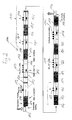
- the device 1 shows a device according to the invention with a configuration for producing white light-emitting organic LEDs (OLEDs).
- the device 1 comprises a multiplicity of vacuum double chambers 2 arranged one behind the other, which are each divided into two parts 3 and 4 and form a vacuum space with their adjacent chambers.
- the vacuum space is also divided by the Masêtbringungsstation 14 and the mask removal station 13 in the embodiment shown in Fig. 1 in two areas, which also have a division into several areas can.
- the subdivision however, the mask deposition and removal stations 13 and 14, as well as the longitudinal division into parts 3 and 4, are to be understood as having different vacuum ratios.
- a separation can take place in that sluices or closure elements 20 are provided, which allow a separation or partitioning off of individual regions of the vacuum space.
- the vacuum space is constructed of similar modules which are differently equipped according to their use as mask application and removal stations or substrate loading and unloading stations, coating stations and the like.
- the device 1 has an overall linear structure, wherein at one end of a Substratseinschleus adopted 5 and at the opposite end a Substratausschleus driving 6 are provided. In addition to the linear structure, of course, another structure with corresponding curves or a transport around the corner is possible.
- substrate insertion device 5 and the Substratausschleus driving 6 a substrate to be coated by environmental conditions or other vacuum treatment plant in the vacuum space of the device 1 are introduced or discharged again.
- Substrate insertion device 5 is followed, after an unspecified lock or closure device, by substrate charging station 7, in which the substrate to be coated is placed on a support 40 (see FIG. 3), on which the substrate strikes during the coating process or during the transport through the device 1 is located.
- the substrate loading station 7 provides a transfer device, as shown in the partial image at the bottom right of FIG. 1, which allows a change of the carrier 40 from the part 4 of the vacuum space in the part 3 of the vacuum space and vice versa. How later is still shown, the carrier 40 in the substrate loading station changes its transport direction from the Suschtransportraum in the substrate transport direction.
- the substrate loading station can also be provided in the substrate inserting device, so that the handling of the substrate during positioning on the substrate carrier can easily take place in air and not in vacuum.
- only one transfer module would join the substrate-inserting device, in which the substrate carrier is transferred from the part 4 into the part 3 and then transported into the substrate-inserting device for loading. Accordingly, the discharge area could be designed.
- the mask application station 8 in which a mask (shadow mask) (see FIG. 3) is placed on the substrate arranged in the carrier 40 in order to achieve a structuring of the coating in the subsequent coating in such a way that the substrate is not coated in the areas covered by the mask, while coating occurs in the other areas.
- the mask is aligned or adjusted here so that the structuring can be carried out in a location-specific manner.
- the mask application station 8 also comprises a transfer device, not shown, by means of which a mask can be transferred from the part 4 of the vacuum space into the part 3 of the vacuum space, wherein at the same time the mask likewise changes the transport direction from a return transport direction into a substrate transport direction.
- a transfer device not shown, by means of which a mask can be transferred from the part 4 of the vacuum space into the part 3 of the vacuum space, wherein at the same time the mask likewise changes the transport direction from a return transport direction into a substrate transport direction.
- the mask application station 8 is adjoined by a multiplicity of vacuum double chambers 2, which are equipped in or on the part 3 for corresponding coating processes.
- coating regions 9, 10 and 11 are provided in which corresponding auxiliary layers, such as hole injection layer HIL, hole transport layer HTL and electron blocking layer EBL in region 9, and the light-emitting material in region 10 and further auxiliary layers, such as electron injection layer EIL, electron transport layer ETL and hole blocking layer HBL are applied in area 11.
- auxiliary layers such as hole injection layer HIL, hole transport layer HTL and electron blocking layer EBL in region 9, and the light-emitting material in region 10 and further auxiliary layers, such as electron injection layer EIL, electron transport layer ETL and hole blocking layer HBL are applied in area 11.
- the carrier After having passed through the coating regions 9 to 11 with the substrate and the mask attached thereto, the carrier passes into the adjoining mask removal station 13 where the mask is removed from the substrate.
- the mask removal station 13 also has a transfer device, by means of which the removed mask is transferred into the part 4 of the vacuum space, in order to be transported back to the mask application station 8 counter to the substrate transport direction, which runs from left to right in the exemplary embodiment of FIG ,
- a mask cleaning station 12 is provided in one of the vacuum double chambers 2, which performs a cleaning of the mask and removal of the placed in the coating stations 9 to 11 coating materials directly on the return transport of the mask. In this way, the mask can be immediately used again in the mask application station 8.
- the cleaning can be done in any suitable way.
- the carrier moves with the substrate into the mask application station 14 located downstream of the mask removal station 13, in which, similar to the mask application station 8, a new mask is again applied to the substrate to provide a correspondingly adapted mask for subsequent electrode application by thermal evaporation ,
- the corresponding mask is transferred from the part 4 of the vacuum space to the part 3 of the vacuum space, the mask changing its transport direction.
- an alignment of the mask is performed, so that the structuring of the applied coating material takes place exactly in the areas in which the structures are necessary.
- the vacuum double chambers 2 following the mask application station 14 are equipped in the region 15 in such a way that thermal evaporation of electrode material onto the substrate can take place.
- thermal evaporation of electrode material onto the substrate can take place.
- other vapor deposition methods are also applicable.
- the substrate on the support and the mask arranged thereon pass into the mask removal station 17, in which the mask is again removed from the substrate and transferred to the part 4 of the vacuum space, so that the mask is transported back against the substrate transport direction and can be cleaned in the cleaning station 16, to then immediately available again in the mask application station.
- the substrate is removed from the carrier and fed to the substrate discharge station 6 while the carrier is transported into the part 4 of the vacuum space and moved back to the substrate loading station 7.
- a common transport of mask and carrier takes place, in which case the carrier in the mask removal station 17 receives the mask for the return transport and emits in the mask application station 14 accordingly.
- the carrier picks up the mask of the preceding coating process in order to transport it to the mask receiving station 8.
- a first endless loop for the carrier of the substrate extending from the substrate loading station 7 in part 3 of the vacuum space (upper row in the picture) via the mask application station 8 and the coating stations 9 to 11 and the mask removal station 13 and the mask receiving station 14 and the coating station 15 are moved to the substrate unloading station 18 in order to change its transport direction and then be transported against the substrate transport direction again to the substrate loading station 7.
- first endless loop there are two second endless loops with respect to the mask transport, on the one hand for the mask for the coating processes in the coating stations 9 to 11 and on the other hand for the mask for the coating process in the coating station 15.
- the mask for the coating process in the coating stations 9 11 moves from the mask application station 8 via the coating stations 9 to 11 to the mask removal station 13 where the mask is in its transport direction changes and is transported back in part 4 of the vacuum space via the mask cleaning station 12 to the mask application station 8.
- the other mask of the coating station coating process 15 moves from mask application station 14 in part 3 of the vacuum space via coating station 15 to mask removal station 17, where it also changes the direction of transport and is transported back in part 4 via cleaning station 16 to mask application station 14.
- endless loops related to the moving objects ie from the viewpoint of the carrier or the masks resulting endless loops can be formed by a variety of handling and transfer devices.
- a single continuous conveyor is provided.
- a simple rotating mechanism can be envisaged in which a support plate 70 is rotated or pivoted about an axis 80, namely 180 °, so that the support plate 70 points once with its corresponding side in the direction of the part 3 of the vacuum space and the other time after the rotation by 180 ° to part 4 of the vacuum space shows.
- the axis of rotation 80 of the pivotable support plate 70 is thus also arranged perpendicular to the image plane.
- a corresponding representation is shown in the lower right part of Fig. 1, wherein the support plate 70 has a central axis 80 about which the support plate 70 is pivotable according to the double arrow, so that the substrate support 40 are rotated between the part 3 and 4 of the vacuum space can.
- FIG. 2 shows a further embodiment of a device according to the invention for the production of so-called RGB displays, in which pixels of red, blue or green emitting electroluminescent materials have to be prepared separately from each other in a structured manner.
- RGB displays in which pixels of red, blue or green emitting electroluminescent materials have to be prepared separately from each other in a structured manner.
- different maskings for the red, green and blue emitting electroluminescent materials to be deposited with corresponding mask deposition and removal stations 124, 125, 126, 127, 128, 129 must be provided.
- a cleaning station 130 is also assigned to the coating station 121 for the red-emitting electroluminescent materials, and a cleaning station 131 for the green coating station 122 and a cleaning station 132 for the corresponding masks to the blue coating station.
- the coating stations 121, 122 and 123 together form the coating area 110 for the electroluminescent material.
- the coating areas 109 and 111 corresponding to the coating areas 9 and 11 of the embodiment of the invention are also Flg. 1, in which the respective auxiliary layers such as hole-inducing layer, hole transport layer, EBL layer, electron-inducing layer, electron transporting layer and HBL layer are applied.
- Cleaning stations 112 and 133 are also assigned to these coating stations 109 and 111 for the masks used there.
- a plasma activation station 119 is provided at the beginning of the device 100, in which the substrate or its surface is plasma-activated for the subsequent coating.
- the device 100 is also divided into two with its vacuum space along the longitudinal axis, into the part 103 and the part 104, wherein in part 103 or correspondingly at the parts 103 of the vacuum double chambers 102 provided there, the corresponding substrate treatment and coating stations 109, 110, 111, 115 and 119 are provided, while the or the parts 104, the cleaning stations 112, 130, 131, 132, 133 and 116 are assigned or arranged on this or in this.
- closure and closing devices 120 are also provided in the embodiment of the device 100, for example between the plasma activation station 119 and the coating station 109 for separating the respective atmospheres and forming a sluice area for the substrates.
- the device 106 has second endless loops for the respective masks, the first mask in the mask application station 108 being placed on the substrate relative to the substrate and aligned with the substrate during passage of the plasma activation station 119 and the coating station 109 in the respective areas to protect and release only to previously defined areas.
- this mask is removed from the substrate or carrier and transported back to the mask application station 108 in the vacuum subspace 104, passing through the mask cleaning station 112.
- the mask deposition and alignment station 108 may also be provided between the plasma activation station 119 and the coating station 109.
- other processing techniques for cleaning and / or activation of the surface in particular surface activation techniques are conceivable, such as UV ozone treatment or ion bombardment.
- the second endless loop of the second type for transporting a corresponding mask is provided for the coating area 121, wherein the mask is applied and adjusted in the mask application station 114 and removed from the substrate or carrier in the mask removal station 124 and cleaned in the cleaning station 130.
- the third, fourth, fifth and sixth endless loops of the second type are assigned to the coating stations 122, 123, 111 and 115, wherein the mask for the subsequent coating process is applied to the substrate or the carrier in the respective mask application stations 125, 127, 129 and 135 and are aligned, while in the arranged after the respective coating stations Maskabdgingstationen 126, 128, 134 and 117, the corresponding masks are removed again.
- FIGS. 3 and 4 This mode of operation is illustrated by the schematic representations of FIGS. 3 and 4, wherein in FIG. 3 for a partial section of the device 100 from FIG. 2 the transport or movement flow for the carrier 40 and the masks 50 and 51 or 52 is shown. As can be seen clearly in FIG. 3, both the first and the second endless loops always move simultaneously several carriers and masks, so that a high throughput is ensured by the coating system.
- the schematically illustrated first endless loop 140 and the second endless loops 150 can preferably have identical transport means and handling devices for realizing the transport device for the carrier or the transport arrangement for the masks.
- the transfer of the masks when changing from the red coating station 121 to the green coating station 122 in the mask removal station 124 and the mask receiving station 125 is schematically illustrated by, for example, rotatable support plates 70 as shown in FIG.
- the carrier with the mask is transferred from the red coating area 121 by rotation of the carrier plate 70 from the first part 103 of the vacuum space into the second part 104 of the vacuum space, in order to dispense the mask for the red coating area.
- the carrier plate 70 is then rotated back so that the carrier 40 (not shown) arranged on the carrier plate 70 with the substrate arranged thereon again lies in the region of the first part 103 of the vacuum chamber.
- a rotation module 260 with a rotation region 262 and a mask change region 261 is provided.
- the substrate carriers 266 are introduced with correspondingly coated masks, while in the part 204 the substrate carriers 267 are introduced cleaned masks the adjacent coating area are handed over, with the transport directions are opposite.
- this is rotated by 90 °, so that the substrate support 266,267 can be transferred to the adjacent mask change region 261.
- There mask masking systems 264 and 265 are arranged on the outer walls, which take over the masks of the substrate carriers 266.267.
- the substrate carriers are again moved onto the turntable 263, rotated there through 180 °, and reinserted into the mask exchange area 261. There, the substrate carrier 266 then takes over the clean mask of the subsequent coating area, while the substrate carrier 267 moves with the coated mask into the cleaning area of the other coating area after a further rotation through 90 °.
Abstract
Description
Die vorliegende Erfindung betrifft eine Vorrichtung nach dem Oberbegriff des Anspruchs 1 bzw. ein Verfahren zur Herstellung von mit organischen elektrolumineszierenden Materialien (OLED) versehenen Substraten.The present invention relates to a device according to the preamble of claim 1 and a method for producing substrates provided with organic electroluminescent materials (OLED).
Bei technischen Bedienungselementen und in der Unterhaltungselektronik gewinnen flache Bildschirme und Anzeigen zunehmend an Bedeutung. Eine interessante Realisierung derartiger flacher Bildschirme ist durch sogenannte OLED-Displays bzw. -Anzeigen gegeben, bei denen organische elektrolumineszierende Materialien zwischen Elektroden auf einem flachen transparenten Substrat abgeschieden werden, um mittels der Ansteuerung über die Elektroden Lichtemissionen zu erzeugen, die zur Bilddarstellung verwendet werden können.For technical controls and consumer electronics, flat screens and displays are becoming increasingly important. An interesting realization of such flat screens is given by so-called OLED displays, in which organic electroluminescent materials are deposited between electrodes on a flat transparent substrate in order to generate by means of the control via the electrodes light emissions that can be used for image display ,
Zur Herstellung derartiger OLED-Bildschirme werden Vakuumbeschichtungsverfahren eingesetzt, die üblicherweise in sogenannten Cluster Tools angewandt werden. Hierbei gibt es üblicherweise verschiedene um ein Zentrum angeordnete Module, in denen verschiedene Beschichtungsschritte durchgeführt werden, wobei die zu beschichtenden Substrate durch einen zentral angeordneten Roboter in die entsprechenden Module eingeführt, von diesen entnommen und zum nächsten Modul transportiert werden. Eine derartige Technik weist zwar hinsichtlich der Reinheitsanforderungen und Prozessbedingungen in den einzelnen Modulen gewisse Vorteile auf, ist jedoch für eine wirtschaftliche Massenherstellung von entsprechenden OLED-Bildschirmen nicht sinnvoll.For the production of such OLED screens vacuum coating methods are used, which are usually applied in so-called cluster tools. In this case, there are usually various modules arranged around a center, in which different coating steps are carried out, wherein the substrates to be coated are introduced by a centrally arranged robot into the corresponding modules, removed from these and transported to the next module. While such technology has certain advantages in terms of purity requirements and process conditions in the individual modules, it does not make sense for cost-effective mass production of corresponding OLED displays.
Deshalb gibt es bereits im Stand der Technik Vorschläge für sogenannte In-Line-Anlagen, die eine kontinuierliche Abfolge der verschiedenen notwendigen Beschichtungsschritte ermöglichen. Als Beispiele sind hier zu nennen die
In der
In der
In der
Es ist deshalb Aufgabe der vorliegenden Erfindung, eine Beschichtungsanlage bzw. eine Vorrichtung zur insbesondere kontinuierlichen Herstellung von mit organischen elektrolumineszierenden Materialien (OLED) versehenen Substraten, insbesondere OLED-Displays, - Bildschirme, -Anzeigen oder sonstigen OLED-Beleuchtungselementen zu schaffen, bei denen die Nachteile des Standes der Technik vermieden werden und insbesondere eine einfache und günstige Möglichkeit zur massentechnischen Herstellung von OLED-Elementen bei geringem Platzbedarf unter Berücksichtigung hoher Qualitätsansprüche für die OLED-Produkte bereit gestellt wird. Insbesondere soll die entsprechende Vorrichtung einfach herstellbar bzw. das Verfahren einfach betreibbar sein.It is therefore an object of the present invention to provide a coating system or a device for the particularly continuous production of substrates provided with organic electroluminescent materials (OLED), in particular OLED displays, screens, displays or other OLED lighting elements, in which the Disadvantages of the prior art are avoided and in particular a simple and inexpensive way for mass production of OLED elements in a small footprint, taking into account high quality standards for the OLED products is provided. In particular, the corresponding device should be easy to manufacture or the method should be easy to operate.
Diese Aufgabe wird gelöst durch eine Vorrichtung mit den Merkmalen des Anspruchs 1 sowie ein Verfahren mit den Merkmalen des Anspruchs 13. Vorteilhafte Ausgestaltungen sind Gegenstand der abhängigen Ansprüche.This object is achieved by a device having the features of claim 1 and a method having the features of
Die vorgeschlagene Lösung zeichnet sich dadurch aus, dass die Beschichtungsanlage bzw. Vorrichtung nach einem Doppelkammerprinzip aufgebaut wird, d.h. dass der gesamte Vakuumraum der Vakuumbeschichtungsanlage vorzugsweise entlang der Längsachse in zwei Teile unterteilt wird, wobei ein erster Teil des Vakuumraums dazu verwendet wird, die mit den Substraten beladenen Träger zum Transport der Substrate durch die Beschichtungsanlage von der Belade- zur Entladestation zu transportieren und der andere, zweite Teil der Anlage zur Rückführung und Reinigung der Substratträger und insbesondere der für die Strukturierung notwendigen Masken dient. Dies hat den Vorteil, dass eine sehr kompakte Anlage mit echter kontinuierlicher Betriebsweise als so genannte In-Line-Anlage verwirklicht werden kann, wobei sowohl eine Vorratshaltung für Träger als auch von Masken durch die Führung von Trägern und/oder Masken in Endlosschleifen vermieden wird.The proposed solution is characterized in that the coating system or device is constructed according to a dual-chamber principle, i. that the entire vacuum space of the vacuum coating system is preferably divided into two parts along the longitudinal axis, wherein a first part of the vacuum space is used to transport the carriers loaded with the substrates for transporting the substrates through the coating equipment from the loading to the unloading station and the other , Second part of the system for recycling and cleaning of the substrate carrier and in particular the masks necessary for structuring serves. This has the advantage that a very compact system with real continuous operation as a so-called in-line system can be realized, both a stock for carriers and masks by guiding carriers and / or masks is avoided in endless loops.
Durch das Doppelkammerprinzip ist ferner ein einfacher Aufbau und ein einfacher Betrieb, insbesondere auch zur Erzeugung des Vakuums möglich, wobei insbesondere die Doppelkammem als universell verwendbare Module ausgestaltet sein können, so dass je nach Bedarf in den entsprechenden Doppelkammermodulen entsprechende Prozesswerkzeuge und sonstige Einrichtungen angeordnet werden können. Dies erleichtert auch den Umbau deutlich. Außerdem ermöglicht ein derartiger Aufbau einen ununterbrochenen Transport von Substraten bzw. Trägern und/oder Masken zur Mikrostrukturierung der Beschichtungen im Vakuum. Damit wird eine Verunreinigung der Träger oder Masken durch die Umgebung vermieden.Due to the double-chamber principle, a simple structure and a simple operation, in particular also for generating the vacuum is possible, wherein in particular the Doppelkammem can be configured as universally usable modules, so that corresponding process tools and other facilities can be arranged as needed in the corresponding double-chamber modules , This also facilitates the conversion significantly. In addition, such a structure allows for a continuous transport of substrates and / or masks for microstructuring the coatings in a vacuum. This avoids contamination of the carriers or masks by the environment.
Ferner können, falls erforderlich, auch Schleusenkammern und/oder Schleuseneinrichtungen sowie Abschließvorrichtungen zwischen den einzelnen Kammern oder Kammermodulen vorgesehen sein, damit bestimmte Bereiche zur Vermeidung von Kontaminationen oder im Falle der teilweisen Belüftung der Anlage abgeschottet werden können.Furthermore, if necessary, lock chambers and / or lock devices as well as closing devices between the individual chambers or chamber modules can be provided so that certain areas can be sealed off to avoid contamination or in the case of partial ventilation of the plant.
Neben der Endlosschleife für den Transport der Träger, die sich mit dem ersten Abschnitt der Transporteinrichtung in Substrattransportrichtung entlang des ersten Teils des Vakuumraums erstreckt und mit dem gegengerichteten zweiten Abschnitt der Transporteinrichtung, also in Trägerrücktransportrichtung, im zweiten Teil des Vakuumraums bzw. der Vakuumdoppelkammem erstreckt, sind in vorteilhafter Weise zusätzlich noch vorzugsweise mehrere zweite Endlosschleifen zum Transport von Masken, die zur Strukturierung bzw. Mikrostrukturierung der Beschichtungen dienen, vorgesehen. Die entsprechenden Transportanordnungen der zweiten Endlosschleifen für den Maskentransport befinden sich mit einem ersten Abschnitt ebenfalls in dem Teil des Vakuumraums, in dem der Substrattransport vom Einschleusbereich in den Ausschleusbereich stattfindet und mit einem zweiten Abschnitt für den Rücktransport im zweiten Teil des Vakuumraums.In addition to the endless loop for the transport of the carrier, which extends with the first section of the transport device in the substrate transport direction along the first part of the vacuum space and with the oppositely directed second section of the transport device, ie in Trägerrücktransportrichtung, in the second part of the vacuum chamber or the Vakuumdoppelkammem extends, are advantageously additionally additionally preferably provided a plurality of second endless loops for the transport of masks, which serve for structuring or microstructuring of the coatings. The corresponding transport arrangements of the second endless loops for the mask transport are also located with a first section in the part of the vacuum space in which the substrate transport takes place from the entry area into the discharge area and with a second section for the return transport in the second part of the vacuum space.
Vorzugsweise verwenden die Transporteinrichtungen für die Träger und die Transportanordnungen für die Masken zum Teil die gleichen Transportmittel und Handhabungseinrichtungen, so dass zumindest teilweise der Transport gemeinsam erfolgt. Insbesondere dienen die Substratträger vorzugsweise auch als Maskenträger für den zumindest teilweisen Rücktransport der Masken.Preferably, the transport devices for the carriers and the transport arrangements for the masks partly use the same means of transport and handling devices, so that at least part of the transport takes place together. In particular, the substrate carriers preferably also serve as mask carriers for the at least partial return transport of the masks.
Vorzugsweise erfolgt der Wechsel von dem ersten Abschnitt der Transporteinrichtung bzw. der Transportanordnung auf den zweiten Abschnitt der Transporteinrichtung bzw. Transportanordnungen in den Endlosschleifen sowie umgekehrt in den Substratladestationen und/oder Substratentladestationen, in denen die Substrate an den Trägern angeordnet bzw. von diesen entfernt werden und/oder in den Maskenaufbringungsstationen und/oder Maskenabnahmestationen, an denen die Masken den Substraten zugeordnet bzw. auf diesen angeordnet werden bzw. wieder von diesen entfernt werden.Preferably, the change from the first section of the transport device or the transport arrangement to the second section of the transport device or transport arrangements takes place in the endless loops and vice versa in the substrate loading stations and / or Substratentladestationen in which the substrates are arranged on the carriers or removed from these and / or in the mask application stations and / or mask removal stations, at which the masks are assigned to the substrates or are arranged on these or removed therefrom.
Nach einer bevorzugten Ausführungsform ist ein Rotationsmodul vorgesehen, welches in einer Station sowohl den Maskenwechsel für zwei benachbarte Beschichtungsbereiche durchführt als auch den Transfer der Masken von dem Beschichtungsabschnitt in den Reinigungsabschnitt und umgekehrt bewerkstelligt, wobei an dem Rotationsmodul entsprechende Maskenaufbringungs- und/oder -abnahmestationen und/oder Maskenausrichtungsstationen sowie Halteelemente für die Masken vorgesehen sind. Das Rotationsmodul umfasst einen Drehmechanismus mit einem Drehtisch, an dem zwei Aufnahmen mit Übergabepositionen für Substratträger sowohl aus dem ersten Abschnitt als auch aus dem zweiten Abschnitt der Transporteinrichtung vorgesehen sind, wobei durch Drehung des Drehtisches um 180° die Auf nahmen in Übergabepositionen des jeweiligen anderen Transportabschnitts und bei Drehung um 90° in Übergabepositionen zur Überführung in einen benachbart angeordneten Maskenwechselbereich gebracht werden können. Zunächst werden hierbei die Masken von den Substratträgem abgenommen, dann werden die Substratträger der jeweils anderen wartenden Maske zugeordnet und nach Aufbringung im Transportsystem weiter bewegt.According to a preferred embodiment, a rotation module is provided, which performs both the mask change for two adjacent coating areas in one station as well as the transfer of the masks from the coating section into the cleaning section and vice versa, wherein on the rotation module corresponding mask application and / or removal stations and Masks and masking and holding elements for the masks are provided. The rotary module comprises a rotating mechanism with a turntable on which two receptacles are provided with transfer positions for substrate carriers from both the first section and from the second section of the transport device, wherein by rotation of the turntable to 180 ° took on the take in transfer positions of the other transport section and can be placed in transfer positions for transfer into an adjacently arranged mask exchange region when rotated by 90 °. First of all, the masks from the Substratträgem removed, then the substrate carriers are assigned to each other waiting mask and moved after application in the transport system on.
Die Endlosschleifen können durch jeweils eine einzige kontinuierlich arbeitende Transporteinrichtung oder durch eine Vielzahl von Handhabungsgeräten und Transportmitteln, bei denen beispielsweise die Substrate und/oder Träger bzw. die Masken von einer Einrichtung auf die andere übergeben werden, realisiert werden.The endless loops can be realized by a single continuously operating transport device or by a plurality of handling devices and transport means, in which, for example, the substrates and / or carriers or the masks are transferred from one device to the other.
Durch die erfindungsgemäße Ausgestaltung der Vorrichtung ist es möglich, bei entsprechenden Verfahren zur Herstellung von OLED-Elementen, die für die Strukturierung der Beschichtungen notwendigen Masken bzw. Schattenmasken direkt auf dem Rücktransport zu reinigen und eine Maskenvorratshaltung zu vermeiden sowie insgesamt die Anzahl der erforderlichen Masken zu minimieren.Due to the inventive design of the device, it is possible in corresponding processes for the production of OLED elements to clean the necessary for the structuring of the coatings masks or shadow masks directly on the return transport and to avoid mask stockpiling and a total of the required number of masks minimize.
Weitere Vorteile, Kennzeichen und Merkmale der vorliegenden Erfindung werden bei der nachfolgenden detaillierten Beschreibung zweier Ausführungsbeispiele anhand der beigefügten Zeichnungen deutlich. Die Zeichnungen zeigen hierbei in rein schematische Weise in
- Fig. 1
- eine Draufsicht auf eine erfindungsgemäße Vorrichtung;
- Fig. 2
- eine Draufsicht auf eine zweite Ausführungsform einer erfindungsgemäßen Vorrichtung;
- Fig. 3
- eine Teilansicht der Vorrichtung aus Fig. 2 mit entsprechenden Trägern und Masken;
- Fig. 4
- eine schematische Darstellung eines Teils des Verfahrensablaufs bzw. -betriebs der Vorrichtung aus Fig. 2 und 3; und in
- Fig. 5
- eine Draufsicht auf ein Rotationsmodul in einer weiteren Ausführungsform der Erfindung.
- Fig. 1
- a plan view of a device according to the invention;
- Fig. 2
- a plan view of a second embodiment of a device according to the invention;
- Fig. 3
- a partial view of the device of Figure 2 with corresponding carriers and masks.
- Fig. 4
- a schematic representation of a part of the process sequence or operation of the apparatus of Figures 2 and 3. and in
- Fig. 5
- a plan view of a rotary module in a further embodiment of the invention.
Fig. 1 zeigt eine erfindungsgemäße Vorrichtung mit einer Konfiguration zur Erzeugung von weißem Licht emittierenden organischen LEDs (OLED). Die Vorrichtung 1 umfasst eine Vielzahl von hintereinander angeordneten Vakuumdoppelkammern 2, die jeweils zweigeteilt in die Teile 3 und 4 sind und mit ihren Nachbarkammern einen Vakuumraum bilden. Neben der Teilung des Vakuumraums in die beiden Teile 3 und 4 entlang der Längsachse der Vorrichtung ist der Vakuumraum zudem durch die Maskenaufbringungsstation 14 und die Maskenabnahmestation 13 in dem in Fig. 1 gezeigten Ausführungsbeispiel in zwei Bereiche unterteilt, wobei auch eine Unterteilung in mehrere Bereiche vorliegen kann. Die Unterteilung durch die Maskenaufbringungs- und -abnahmestationen 13 und 14 ist jedoch genauso wenig wie die Längsunterteilung in die Teile 3 und 4 dahingehend zu verstehen, dass unterschiedliche Vakuumverhältnisse vorliegen. Obwohl dies im Einzelfall möglich ist, können vielmehr auch gleiche Vakuumverhältnisse herrschen. Die Unterteilung ist nur dahingehend zu verstehen, dass der Vakuumraum nicht gleich bleibend durchgängig ist. Allerdings bilden die Vakuumdoppelkammern 2 mit ihren jeweiligen Teilen 3 und 4 durchgängig Transportbereiche, die auch durch die Maskenaufbringungs- und -abnahmestationen 13 und 14 nicht unterbrochen werden, während ein Übergang zwischen den Teilen 3 und 4 nur in bestimmten Bereichen möglich ist. Auch die Unterteilung des Vakuumraums durch die Module der Vakuumdoppelkammem 2 beeinflusst die grundsätzliche Unterteilung in die Teile 3 und 4 nicht.1 shows a device according to the invention with a configuration for producing white light-emitting organic LEDs (OLEDs). The device 1 comprises a multiplicity of vacuum double chambers 2 arranged one behind the other, which are each divided into two
Zusätzlich kann eine Trennung dadurch erfolgen, dass Schleusen oder Abschließelemente 20 vorgesehen sind, die eine Abtrennung bzw. Abschottung einzelner Bereiche des Vakuumraums ermöglichen. Vorzugsweise ist der Vakuumraum aus gleichartigen Modulen aufgebaut, die entsprechend ihrer Verwendung als Maskenaufbringungs- und -abnahmestationen oder Substratlade- und -entladestationen, Beschichtungsstationen und dergleichen unterschiedlich ausgestattet sind.In addition, a separation can take place in that sluices or
Die Vorrichtung 1 weist insgesamt einen linearen Aufbau auf, wobei an dem einen Ende eine Substrateinschleuseinrichtung 5 und am gegenüberliegenden Ende eine Substratausschleuseinrichtung 6 vorgesehen sind. Neben dem linearen Aufbau ist selbstverständlich auch ein anderer Aufbau mit entsprechenden Kurven oder einem Transport um die Ecke möglich. Durch die Substrateinschleuseinrichtung 5 und die Substratausschleuseinrichtung 6 kann ein zu beschichtendes Substrat von Umgebungsbedingungen oder einer anderen Vakuumbehandlungsanlage in den Vakuumraum der Vorrichtung 1 eingeschleust bzw. wieder ausgeschleust werden.The device 1 has an overall linear structure, wherein at one end of a Substratseinschleuseinrichtung 5 and at the opposite end a Substratausschleuseinrichtung 6 are provided. In addition to the linear structure, of course, another structure with corresponding curves or a transport around the corner is possible. By substrate insertion device 5 and the Substratausschleuseinrichtung 6, a substrate to be coated by environmental conditions or other vacuum treatment plant in the vacuum space of the device 1 are introduced or discharged again.
An die Substrateinschleuseinrichtung 5 schließt sich nach einer nicht näher bezeichneten Schleus- oder Abschließvorrichtung die Substratladestation 7 an, bei der das zu beschichtende Substrat auf einem Träger 40 (siehe Fig. 3) angeordnet wird, auf dem sich das Substrat während des Beschichtungsprozesses bzw. während des Transports durch die Vorrichtung 1 befindet. Gleichzeitig stellt die Substratladestation 7 eine Transfereinrichtung, wie im Teilbild rechts unten von Fig. 1 dargestellt, bereit, die einen Wechsel des Trägers 40 aus dem Teil 4 des Vakuumraums in den Teil 3 des Vakuumraums ermöglicht und umgekehrt. Wie später noch gezeigt wird, wechselt der Träger 40 in der Substratladestation seine Transportrichtung von der Trägerrücktransportrichtung in die Substrattransportrichtung.Substrate insertion device 5 is followed, after an unspecified lock or closure device, by
Alternativ (nicht gezeigt) kann die Substratladestation auch in der Substrateinschleuseinrichtung vorgesehen sein, so dass das Handling des Substrats beim Positionieren auf dem Substratträger in einfacher Weise an Luft und nicht im Vakuum stattfinden kann. In diesem Fall würde sich an die Substrateinschleuseinrichtung lediglich eine Transfermodul anschließen, bei dem der Substratträger aus dem Teil 4 in den Teil 3 überführt und anschließend zur Beladung in die Substrateinschleuseinrichtung transportiert wird. Entsprechend könnte auch der Ausschleusbereich gestaltet sein.Alternatively (not shown), the substrate loading station can also be provided in the substrate inserting device, so that the handling of the substrate during positioning on the substrate carrier can easily take place in air and not in vacuum. In this case, only one transfer module would join the substrate-inserting device, in which the substrate carrier is transferred from the part 4 into the
Nach der Substratladestation 7 folgt die Maskenaufbringungsstation 8, bei der auf das im Träger 40 angeordnete Substrat ein Maske (Schattenmaske) (siehe Fig. 3) aufgesetzt oder zugeordnet wird, um bei der nachfolgenden Beschichtung eine Strukturierung der Beschichtung in der Weise zu erzielen, dass das Substrat in den von der Maske abgedeckten Bereichen nicht beschichtet wird, während in den anderen Bereichen eine Beschichtung erfolgt. Zusätzlich wird hier die Maske ausgerichtet bzw. justiert, damit die Strukturierung ortsgenau erfolgen kann.Subsequent to the
Auch die Maskenaufbringungsstation 8 umfasst eine nicht näher dargestellte Transfereinrichtung, mit Hilfe der eine Maske aus dem Teil 4 des Vakuumraums in den Teil 3 des Vakuumraums überführt werden kann, wobei gleichzeitig die Maske ebenfalls die Transportrichtung von einer Rücktransportrichtung in eine Substrattransportrichtung wechselt. Bei entsprechender Ausgestaltung mit Handhabungs- und Halteeinrichtungen (nicht gezeigt) können die Substratladestation 7 und die Maskenaufbringungsstation 8 auch in einer einzigen Station kombiniert werden.The
An die Maskenaufbringungsstation 8 schließen sich eine Vielzahl von Vakuumdoppelkammern 2 an, die in oder am Teil 3 für entsprechende Beschichtungsprozesse ausgestattet sind.The
Im gezeigten Ausführungsbeispiel der Fig. 1 sind Beschichtungsbereiche 9, 10 und 11 vorgesehen, bei denen entsprechende Hilfsschichten, wie Löcherinjektionsschicht HIL, Löchertransportschicht HTL und Elektronenblockierschicht EBL im Bereich 9 sowie das Licht emittierende Material im Bereich 10 und weitere Hilfsschichten, wie Elektroneninjektionsschicht EIL, Elektronentransportschicht ETL und Löcherblockierschicht HBL im Bereich 11 aufgebracht werden.In the exemplary embodiment shown in FIG. 1,
Nachdem der Träger mit dem darauf angebrachten Substrat sowie der Maske die Beschichtungsbereiche 9 bis 11 durchlaufen hat, gelangt er in die sich anschließe Maskenabnahmestation 13, in der die Maske von dem Substrat entfernt wird. Auch die Maskenabnahmestation 13 weist eine Transfereinrichtung auf, mittels der die abgenommene Maske in den Teil 4 der Vakuumraums transferiert wird, um dort entgegen der Substrattransportrichtung, die in dem Ausfiihrungsbeispiel der Fig. 1 von links nach rechts verläuft, zur Maskenaufbringungsstation 8 zurück transportiert zu werden. Auf dem Weg dahin ist in einer der Vakuumdoppelkammern 2 eine Maskenreinigungsstation 12 vorgesehen, die direkt beim Rücktransport der Maske eine Reinigung der Maske und Entfernung der in den Beschichtungsstationen 9 bis 11 auf gebrachten Beschichtungsstoffe vornimmt. Auf diese Weise kann die Maske sofort wieder in der Maskenaufbringungsstation 8 eingesetzt werden. Die Reinigung kann in jeder geeigneten Weise erfolgen.After having passed through the
Währenddessen bewegt sich der Träger mit dem Substrat in die nach der Maskenabnahmestation 13 angeordnete Maskenaufbringungsstation 14, in der ähnlich zur Maskenaufbringungsstation 8 wiederum eine neue Maske auf dem Substrat aufgebracht wird, um für die nachfolgende Elektrodenaufbringung durch thermische Verdampfung eine entsprechend angepasste Maske zur Verfügung zu stellen.Meanwhile, the carrier moves with the substrate into the
In der Maskenaufbringungsstation 14 wird die entsprechende Maske genauso wie in der Maskenaufbringungsstation 8 aus dem Teil 4 des Vakuumraums in den Teil 3 des Vakuumraums überführt, wobei die Maske ihre Transportrichtung ändert. Außerdem wird in der Maskenaufbringungsstation 14 genauso wie in der Maskenaufbringungsstation 8 eine Ausrichtung der Maske vorgenommen, so dass die Strukturierung des aufzubringenden Beschichtungsmaterials genau in den Bereichen erfolgt, in denen die Strukturen notwendig sind.In the
Die nach der Maskenaufbringungsstation 14 folgenden Vakuumdoppelkammern 2 sind im Bereich 15 so ausgestattet, dass eine thermische Verdampfung von Elektrodenmaterial auf das Substrat erfolgen kann. Auch andere Aufdampfungsverfahren sind selbstverständlich anwendbar.The vacuum double chambers 2 following the
Nach dem Durchlaufen der Beschichtungsstation 15 gelangt das Substrat auf dem Träger und die darauf angeordnete Maske in die Maskenabnahmestation 17, in der die Maske wiederum vom Substrat entfernt und in den Teil 4 des Vakuumraums überführt wird, so dass die Maske entgegen der Substrattransportrichtung zurück transportiert und in der Reinigungsstation 16 gereinigt werden kann, um anschließend sofort wieder in der Maskenaufbringungsstation zur Verfügung zu stehen.After passing through the coating station 15, the substrate on the support and the mask arranged thereon pass into the mask removal station 17, in which the mask is again removed from the substrate and transferred to the part 4 of the vacuum space, so that the mask is transported back against the substrate transport direction and can be cleaned in the cleaning station 16, to then immediately available again in the mask application station.
In der für den Träger folgenden Substratentladestation 18 wird das Substrat von dem Träger entnommen und der Substratausschleusstation 6 zugeführt, während der Träger in den Teil 4 des Vakuumraums transportiert und zur Substratladestation 7 zurück bewegt wird.In the substrate unloading station 18 following for the carrier, the substrate is removed from the carrier and fed to the substrate discharge station 6 while the carrier is transported into the part 4 of the vacuum space and moved back to the
Beim Rücktransport des Trägers erfolgt der gezeigten bevorzugten Ausführungsform ein gemeinsamer Transport von Maske und Träger, wobei in diesem Fall der Träger in der Maskenabnahmestation 17 die Maske für den Rücktransport aufnimmt und in der Maskenaufbringungsstation 14 entsprechend wieder abgibt. In gleicher Weise nimmt der Träger auf dem Rücktransport im Teil 4 des Vakuumraums in der Maskenabnahmestation 13 die Maske des vorangegangenen Beschichtungsprozesses auf, um sie bis zur Maskenaufnahmestation 8 mitzutransportieren. Allerdings ist es auch vorstellbar getrennte Transportmittel für Träger und Masken für den Rücktransport vorzusehen.During the return transport of the carrier, the preferred embodiment shown, a common transport of mask and carrier takes place, in which case the carrier in the mask removal station 17 receives the mask for the return transport and emits in the
Insgesamt ergeben sich somit in dem Ausführungsbeispiel der Fig. 1 drei Endlosschleifen und zwar eine erste Endlosschleife für den Träger des Substrats, der sich von der Substratladestation 7 im Teil 3 des Vakuumraums (im Bild obere Reihe) über die Maskenaufbringungsstation 8 und die Beschichtungsstationen 9 bis 11 und die Maskenabnahmestation 13 sowie Maskenaufnahmestation 14 und die Beschichtungsstation 15 bis zur Substratentladestation 18 bewegt, um dort seine Transportrichtung zu ändern und dann entgegen der Substrattransportrichtung wiederum bis zur Substratladestation 7 transportiert zu werden. Zusätzlich zu dieser ersten Endlosschleife gibt es zwei zweite Endlosschleifen bezüglich des Maskentransports und zwar einerseits für die Maske für die Beschichtungsprozesse in den Beschichtungsstationen 9 bis 11 und andererseits für die Maske für den Beschichtungsprozess in der Beschichtungsstation 15. Die Maske für den Beschichtungsprozess in den Beschichtungsstationen 9 bis 11 bewegt sich von der Maskenaufbringungsstation 8 über die Beschichtungsstationen 9 bis 11 bis zur Maskenabnahmestation 13, wo die Maske ihre Transportrichtung ändert und im Teil 4 des Vakuumraums über die Maskenreinigungsstation 12 zur Maskenaufbringungsstation 8 zurück transportiert wird.Thus, in the exemplary embodiment of FIG. 1, there are three endless loops, namely a first endless loop for the carrier of the substrate extending from the
Die andere Maske des Beschichtungsprozesses der Beschichtungsstation 15 bewegt sich von der Maskenaufbringungsstation 14 im Teil 3 des Vakuumraums über die Beschichtungsstation 15 zur Maskenabnahmestation 17, wo sie ebenfalls die Transportrichtung ändert und im Teil 4 über die Reinigungsstation 16 zur Maskenaufbringungsstation 14 zurück transportiert wird.The other mask of the coating station coating process 15 moves from
Diese auf die bewegten Gegenstände bezogenen Endlosschleifen, also aus der Sicht des Trägers bzw. der Masken sich ergebenden Endlosschleifen können durch eine Vielzahl von Handhabungs- und Übergabeeinrichtungen gebildet werden. Allerdings ist auch vorstellbar, dass insbesondere für die Bewegung des Trägers eine einzige kontinuierliche Beförderungseinrichtung vorgesehen ist.These endless loops related to the moving objects, ie from the viewpoint of the carrier or the masks resulting endless loops can be formed by a variety of handling and transfer devices. However, it is also conceivable that, in particular for the movement of the carrier, a single continuous conveyor is provided.
In gleicher Weise sind für die Substratlade- bzw. -entladestationen 7 und 18 sowie die Maskenaufbringungs- und -abnahmestationen 8 und 14 einerseits sowie 13 und 17 andererseits vielfältige Betätigungsvorrichtungen zur Aufnahme und Bewegung der Masken, Träger, Substrate usw. denkbar.In the same way, for the substrate loading and unloading
Als Transfereinrichtung ist beispielsweise für die Substratlade- und -entladestationen 7 und 18 sowie die Maskenaufbringungs- und -abnahmestationen 8, 13, 14 und 17 ein einfacher Drehmechanismus vorstellbar, bei dem eine Trägerplatte 70 um eine Achse 80 verdreht bzw. geschwenkt wird, und zwar um 180°, so dass die Trägerplatte 70 einmal mit ihrer entsprechenden Seite in Richtung des Teils 3 des Vakuumraums weist und das andere Mal nach der Drehung um 180° zum Teil 4 des Vakuumraums zeigt. Bei einer vertikalen Ausrichtung des Substrats, also einer Ausrichtung senkrecht zur Bildebene der Fig. 1 und einem entsprechenden vertikalen Transport, ist die Drehachse 80 der verschwenkbaren Trägerplatte 70 somit ebenfalls senkrecht zur Bildebene angeordnet. Eine entsprechende Darstellung ist im rechten unteren Teil der Fig. 1 gezeigt, wobei die Trägerplatte 70 eine mittige Achse 80 aufweist, um die die Trägerplatte 70 gemäß des Doppelpfeils verschwenkbar ist, so dass der Substratträger 40 zwischen dem Teil 3 und 4 des Vakuumraums gedreht werden kann.As a transfer device, for example, for the substrate loading and unloading
Auf diese Weise ist es auch besonders einfach, eine Kombination von Substratlade- bzw. -entladestationen 7, 18 und Maskenaufbringungs- und -abnahmestationen 8, 13, 14, 17, 18, beispielsweise von Maskenabnahmestation 13 und Maskenaufbringungsstation 14 zu realisieren, da lediglich entsprechende Zwischenhalteeinrichtungen für die abzunehmenden und aufzubringenden Teile vorgesehen sein müssen. Ein entsprechendes Rotationsmodul wird nachfolgend im Zusammenhang mit Fig. 5 beschrieben.In this way, it is also particularly easy to use a combination of substrate loading and unloading
Die Fig. 2 zeigt ein weiteres Ausführungsbeispiel einer erfindungsgemäßen Vorrichtung für die Herstellung von so genannten RGB-Displays, bei denen Pixel von rot-, blau- bzw. grün emittierenden elektrolumineszierenden Materialien in strukturierter Weise separat voneinander hergestellt werden müssen. Entsprechend müssen unterschiedliche Maskierungen für die abzuscheidenden rot-, grün- und blau emittierenden elektrolumineszierenden Materialien mit entsprechenden Maskenaufbringungs- und -abnahmestationen 124, 125, 126, 127, 128, 129 vorgesehen werden. Entsprechend ist auch der Beschichtungsstation 121 für die rot emittierenden elektrolumineszierenden Materialien eine Reinigungsstation 130 sowie für die grüne Beschichtungsstation 122 eine Reinigungsstation 131 und der blauen Beschichtungsstation eine Reinigungsstation 132 für die entsprechenden Masken zugeordnet.2 shows a further embodiment of a device according to the invention for the production of so-called RGB displays, in which pixels of red, blue or green emitting electroluminescent materials have to be prepared separately from each other in a structured manner. Accordingly, different maskings for the red, green and blue emitting electroluminescent materials to be deposited with corresponding mask deposition and
Die Beschichtungsstationen 121, 122 und 123 bilden zusammen den Beschichtungsbereich 110 für das elektrolumineszierende Material. Darüber hinaus sind auch die Beschichtungsbereiche 109 und 111 entsprechend den Beschichtungsbereichen 9 und 11 der Ausfi.ihrungsform der Flg. 1 vorgesehen, in der die entsprechenden Hilfsschichten wie Löcher induzierende Schicht, Löchertransportschicht, EBL-Schicht, Elektronen induzierende Schicht, Elektrone transportierende Schicht und HBL-Schicht aufgebracht werden. Auch diesen Beschichtungsstationen 109 und 111 sind für die dort verwendeten Masken Reinigungsstationen 112 und 133 zugeordnet. Darüber hinaus ist neben der Elektrodenbeschichtungsstation 115 eine Plasmaaktivierungsstation 119 am Beginn der Vorrichtung 100 vorgesehen, bei der das Substrat bzw. dessen Oberfläche für die nachfolgende Beschichtung plasmaaktiviert wird.The
Auch die Vorrichtung 100 ist mit ihrem Vakuumraum entlang der Längsachse zweigeteilt, in den Teil 103 und den Teil 104, wobei in Teil 103 bzw. entsprechend an den dort vorgesehenen Teilen 103 der Vakuumdoppelkammern 102 die entsprechenden Substratbehandlungs- und Beschichtungsstationen 109, 110, 111, 115 und 119 vorgesehen sind, während dem oder den Teilen 104 die Reinigungsstationen 112, 130, 131, 132, 133 und 116 zugeordnet bzw. an diesen oder in diesen angeordnet sind.The
Ähnlich wie die Schleusen- oder Abschließvorrichtung 20 des Ausführungsbeispiels der Fig. 1 zum Abtrennen bzw. Abschotten einzelner Bereiche, insbesondere im Bereich der Maskenaufbringung- und -abnahmestationen sind auch bei der Ausführungsform der Vorrichtung 100 entsprechende Schleusen- bzw. Abschließvorrichtungen 120 vorgesehen, die beispielsweise zwischen der Plasmaaktivierungsstation 119 und der Beschichtungsstation 109 zur Abtrennung der entsprechenden Atmosphären und Bildung eines Schleusenbereichs für die Substrate vorgesehen sind.Similar to the lock or
Insgesamt ergibt sich somit ein Aufbau der Vorrichtung 100 mit einer Substrateinschleusstation 105, einer Substratladestation 107, einer Maskenaufbringungsstation 108 und einer Endlosschleife für den Träger mit nicht näher dargestellten Transportmitteln, die den Träger mit aufgebrachtem Substrat und wechselnden Masken zunächst an der Plasmaaktivierungsstation 119, anschließend an der Beschichtungsstation 109 sowie den weiteren Beschichtungsstationen 121, 122, 123 und 111 sowie 115 vorbeibewegt, um schließlich in der Substratentladestation 118 das Substrat von dem Träger zu trennen und das Substrat in der Substratausschleusstation 106 auszugeben bzw. nachfolgenden Behandlungseinrichtungen zur Verfügung zu stellen. Der Träger wird dann ohne Substrat und wiederum mit wechselnden Masken im zweiten Teil 104 des Vakuumraumes zur Substratladestation 107 zurückbewegt, wobei er die Reinigungsstationen 116, 133, 132, 131, 130 und 112 in dieser Reihenfolge passiert.Overall, this results in a structure of the
Neben dieser ersten Endlosschleife weist die Vorrichtung 106 zweite Endlosschleifen für die entsprechenden Masken auf, wobei die erste Maske in der Maskenaufbringungsstation 108 auf das Substrat bzw. auf den Träger in Bezug zu dem Substrat angeordnet und ausgerichtet wird, um das Substrat während des Passierens der Plasmaaktivierungsstation 119 und der Beschichtungsstation 109 in den entsprechenden Bereichen zu schützen und nur gegenüber vorher definierten Bereiche freizugeben. In der Maskenabnahmestation 113 wird diese Maske von dem Substrat bzw. dem Träger entfernt und im Vakuumteilraum 104 unter Passieren der Maskenreinigungsstation 112 zur Maskenaufbringungsstation 108 zurücktransportiert. Falls eine Plasmaaktivierung der gesamten Oberfläche des Substrats gewünscht wird, kann die Maskenaufbringungs- und -ausrichtungsstation 108 auch zwischen der Plasmaaktivierungsstation 119 und der Beschichtungsstation 109 vorgesehen werden. Anstelle der Plasmaaktivierung sind auch andere Bearbeitungstechniken zur Reinigung und/oder Aktivierung für die Oberfläche, insbesondere Oberflächenaktivierungstechniken denkbar, wie UV-OzonBehandlung oder Ionenbeschuss.In addition to this first infinite loop, the
Die zweite Endlosschleife zweiter Art zum Transport einer entsprechenden Maske ist für den Beschichtungsbereich 121 vorgesehen, wobei die Maske in der Maskenaufbringungsstation 114 aufgebracht und justiert und in der Maskenabnahmestation 124 vom Substrat bzw. Träger entfernt und in der Reinigungsstation 130 gereinigt wird.The second endless loop of the second type for transporting a corresponding mask is provided for the
Die dritte, vierte, fünfte und sechste Endlosschleife zweiter Art ist den Beschichtungsstationen 122, 123, 111 und 115 zugeordnet, wobei jeweils in den entsprechenden Maskenaufbringungsstationen 125, 127, 129 und 135 die Masken für den nachfolgenden Beschichtungsprozess auf das Substrat bzw. dem Träger aufgebracht und ausgerichtet werden, während in den nach den jeweiligen Beschichtungsstationen angeordneten Maskenabnahmestationen 126, 128, 134 und 117 die entsprechenden Masken wieder entfernt werden.The third, fourth, fifth and sixth endless loops of the second type are assigned to the
Diese Funktionsweise wird durch die schematischen Darstellungen der Fig. 3 und 4 noch verdeutlicht, wobei in Fig. 3 für einen Teilabschnitt der Vorrichtung 100 aus Fig. 2 der Transport- bzw. Bewegungsfluss für den Träger 40 und die Masken 50 und 51 bzw. 52 dargestellt ist. Wie in Fig. 3 deutlich zu sehen ist, bewegen sich sowohl in den ersten als auch in den zweiten Endlosschleifen gleichzeitig immer mehrere Träger und Masken, so dass ein hoher Durchsatz durch die Beschichtungsanlage gewährleistet ist. Wie durch die Doppelpfeile in den Maskenaufbringungsstationen 108, 114 und 125 sowie den Maskenabnahmestationen 113 und 124 sowie der Substratladestation 107 angedeutet ist, erfolgt in diesen Stationen der Wechsel des Trägers 40 von dem zweiten Abschnitt der Transporteinrichtung für den Träger im Teil 104 des Vakuumraums auf den ersten Abschnitt der Transporteinrichtung im Teil 103 des Vakuumraums bzw. für die Masken von dem zweiten Abschnitt der Transportanordnung für die Masken im Teil 104 des Vakuumraums auf den ersten Abschnitt der Transportanordnung der Masken im Teil 103 des Vakuumraums (Maskenaufbringungsstationen) bzw. umgekehrt (Maskenabnahmestationen).This mode of operation is illustrated by the schematic representations of FIGS. 3 and 4, wherein in FIG. 3 for a partial section of the
Wie sich insbesondere aus Fig. 4 ergibt, können die schematisch dargestellte erste Endlosschleife 140 und die zweiten Endlosschleifen 150 vorzugsweise identische Transportmittel und Handhabungseinrichtungen zur Realisierung der Transporteinrichtung für den Träger bzw. der Transportanordnung für die Masken aufweisen.As can be seen in particular from FIG. 4, the schematically illustrated first
In Fig. 4 ist die Übergabe der Masken beim Wechsel von der roten Beschichtungsstation 121 auf die grüne Beschichtungsstation 122 in der Maskenabnahmestation 124 und der Maskenaufnahmestation 125 durch beispielsweise drehbare Trägerplatten 70, wie in Fig. 1 dargestellt, schematisch visualisiert. In der Maskenabnahmestation 124 wird der Träger mit der Maske aus dem roten Beschichtungsbereich 121 durch Drehung der Trägerplatte 70 von dem ersten Teil 103 des Vakuumraums in den zweiten Teil 104 des Vakuumraums überführt, um dort die Maske für den roten Beschichtungsbereich abzugeben. Dann wird die Trägerplatte 70 zurückgedreht, so dass der auf der Trägerplatte 70 angeordnete Träger 40 (nicht gezeigt) mit dem darauf angeordneten Substrat sich wieder im Bereich des ersten Teils 103 des Vakuumraums befindet. Dann folgt der Weitertransport des Substrats mit dem Träger in die Maskenaufbringungsstation 125 des grünen Bereichs 122, wobei hier zunächst wiederum die Trägerplatte 70 um 180° gedreht wird, so dass das Substrat mit dem Träger wiederum im Teil 104 des Vakuumraums angeordnet ist. Dort übernimmt der Träger bzw. das Substrat die im Teil 104 des Vakuumraums zurücktransportierte und gereinigte Maske des grünen Bereichs um nach der Anordnung und Ausrichtung der grünen Maske wieder durch eine Drehung um 180° in den Teil 103 des Vakuumraums zurückgedreht zu werden, so dass dort der Transport des Trägers mit Substrat und nunmehr grüner Maske durch den grünen Bereich fortgesetzt werden kann. Eine derartige Abfolge ist zwischen allen Beschichtungs- bzw. Substratbehandlungsstationen und auch für die Substratlade- und -entladestation realisierbar.4, the transfer of the masks when changing from the
Bei Verwendung entsprechender Handhabungsmittel, die eine kurzfristige Zwischenlagerung von zumindest jeweils einer der entsprechenden Masken erlauben, ist auch die Kombination von Maskenaufbringungs- und Maskenabnahmestationen in einer einzigen Station vorstellbar, wie dies in Fig. 5 gezeigt ist. Allerdings ist zur Vermeidung von gegenseitigen Kontaminationen der verschiedenen Beschichtungsbereiche die räumliche Trennung vorteilhaft, auch wenn dies einen etwas höheren Handhabungsaufwand darstellt. Für Beschichtungsstationen oder Substratbehandlungsstationen, in denen jedoch keine Kontaminationen zu befürchten sind oder wenn entsprechende Abtrennungen vorgesehen sind, kann eine derartige Kombination verwirklicht werden.When using appropriate handling means, which allow a short-term temporary storage of at least one of the respective masks, the combination of mask application and mask removal stations in a single station is conceivable, as shown in Fig. 5. However, in order to avoid mutual contamination of the various coating areas, the spatial separation is advantageous, even if this represents a somewhat higher handling effort. For coating stations or substrate treatment stations, however, in which no contamination is to be feared or if appropriate separations are provided, such a combination can be realized.
Im Beispiel der Fig. 5 ist ein Rotationsmodul 260 mit einem Drehbereich 262 und einem Maskenwechselbereich 261 vorgesehen. In das Rotationsmodul 260 werden im Teil 203 der Transporteinrichtung, in der die Beschichtung stattfindet, die Substratträger 266 mit entsprechend beschichteten Masken eingebracht, während im Teil 204 die Substratträger 267 mit gereinigten Masken des benachbarten Beschichtungsbereich übergeben werden, wobei die Transportrichtungen entgegengesetzt sind. Nach Aufnahme der Substratträger 266,267 auf dem Drehtisch 263 wird dieser um 90° gedreht, so dass die Substratträger 266,267 in den benachbarten Maskenwechselbereich 261 überführt werden können. Dort sind an den Außenwänden Maskenpositioniersysteme 264 und 265 angeordnet, die die Masken von den Substratträgern 266,267 übernehmen. Während die Maskenpositioniersysteme 264 und 265 die Masken halten, werden die Substratträger wieder auf den Drehtisch 263 bewegt, dort um 180° gedreht und wieder in den Maskenwechselbereich 261 eingebracht. Dort übernimmt dann der Substratträger 266 die saubere Maske des nachfolgenden Beschichtungsbereichs, während der Substratträger 267 mit der beschichteten Maske nach einer weiteren Drehung um 90° in den Reinigungsbereich des anderen Beschichtungsbereichs fährt.In the example of FIG. 5, a
Claims (18)
dadurch gekennzeichnet, dass
die Transporteinrichtung zumindest eine Endlosschleife (140) für den Transport der Träger (40) umfasst, wobei der Vakuumraum zumindest zweigeteilt mit einem ersten Teil (3,103), in dem ein erster Abschnitt der Transporteinrichtung für den Transport der Träger (40) in eine erste Richtung (Substrattransportrichtung) vorgesehen ist, und mit einem zweiten Teil (4,104) ist, in dem ein zweiter Abschnitt der Transporteinrichtung für den Transport der Träger in eine zweite Richtung (Trägerrücktransportrichtung) vorgesehen ist.Device for in particular continuous production of substrates provided with organic electroluminescent materials (OLED), in particular OLED displays, screens, displays or other lighting elements, with a vacuum space and a transport device for transporting the substrates to be coated, which are arranged at least partially along the vacuum space is and has substrates for the substrates,
characterized in that
the transport device comprises at least one endless loop (140) for transporting the carriers (40), the vacuum space being at least two-parted with a first part (3, 103) in which a first portion of the transport device for transporting the carriers (40) in a first direction (Substrate transport direction) is provided, and with a second part (4,104), in which a second portion of the transport device for the transport of the carrier in a second direction (Trägerrücktransportrichtung) is provided.
dadurch gekennzeichnet, dass
der Vakuumraum aus einer Vielzahl von nebeneinander angeordneten Kammern (2,102) aufgebaut ist, die voneinander abtrennbar sind und einen ununterbrochenen Transport der Substrate und/oder Träger (40) und/oder Masken (50,51,52) im Vakuum erlauben und/oder dass zusätzlich Schleusenkammern und/oder -einrichtungen (20,120) entlang der Endlosschleife vorgesehen sind.Device according to claim 1,
characterized in that
the vacuum space is constructed from a multiplicity of juxtaposed chambers (2, 102) which are separable from one another and permit uninterrupted transport of the substrates and / or carriers (40) and / or masks (50, 51, 52) in a vacuum and / or additionally lock chambers and / or means (20,120) are provided along the endless loop.
dadurch gekennzeichnet, dass
die Zweiteilung des Vakuumraums durch Vakuumdoppelkammern (2,102) gebildet ist, die zumindest teilweise hintereinander angeordnet sind.Device according to one of the preceding claims,
characterized in that
the division of the vacuum space by vacuum double chambers (2,102) is formed, which are at least partially arranged one behind the other.
dadurch gekennzeichnet, dass
mindestens eine zweite, vorzugsweise mehrere zweite Endlosschleifen (150) zum Transport von Masken (50,51,52) im Vakuumraum vorgesehen sind, vorzugsweise jeweils eine für den Bereich (10,110) der Abscheidung von organischen elektrolumineszierenden Materialien, insbesondere von rot (121), grün (122) und blau (123) emittierenden organischen elektrolumineszierenden Elementen, wobei insbesondere ein erster Abschnitt der Transportanordnung der zweiten Endlosschleife (150) im ersten Teil (3,103) des Vakuumraums und ein zweiter Abschnitt der Transportanordnung der zweiten Endlosschleife (150) im zweiten Teil (4,104) des Vakuumraums vorgesehen sind.Device according to one of the preceding claims,
characterized in that
at least one second, preferably a plurality of second endless loops (150) are provided for the transport of masks (50, 51, 52) in the vacuum space, preferably one in each case for the region (10, 110) of the deposition of organic electroluminescent materials, in particular of red (121), green (122) and blue (123) emitting organic electroluminescent elements, in particular a first section of the transport arrangement of the second endless loop (150) in the first part (3,103) of the vacuum space and a second portion of the transport arrangement of the second endless loop (150) in the second part (4,104) of the vacuum space are provided.
dadurch gekennzeichnet, dass
mindestens jeweils eine, vorzugsweise mehrere Substratlade- (7,107) und - entladestationen (18,118) für die Anordnung bzw. Entladung der Substrate vom Träger und/oder Maskenaufbringungs- und/oder -abnahmestationen und/oder Maskenausrichtungsstationen (8,13,14,17;108,113,114,117,124,125,126,127,128,129,134,13 5) vorgesehen sind.Device according to one of the preceding claims,
characterized in that
at least one, preferably a plurality of substrate loading (7,107) and unloading stations (18,118) for the placement or unloading of the substrates from the support and / or mask application and / or removal stations and / or mask alignment stations (8,13,14,17; 108,113,114,117,124,125,126,127,128,129,134,13 5) are provided.
dadurch gekennzeichnet, dass
Transfereinrichtungen, insbesondere in den Substratlade- (7,107) und -entladestationen (18,118) und/oder Maskenaufbringungs- und -abnahmestationen (8,13,14,17;108,113,114,117,124,125,126,127,128,129,134,135) zum Wechsel von Trägern (40) und/oder Masken (50,51,52) von dem ersten Teil (3,103) des Vakuumraums zum zweiten Teil (4,104) und umgekehrt.Device according to one of the preceding claims,
characterized in that
Transfer means, in particular in the substrate loading (7,107) and unloading stations (18,118) and / or mask application and removal stations (8,13,14,17; 108,113,114,117,124,125,126,127,128,129,134,135) for changing carriers (40) and / or masks (50,51 , 52) from the first part (3, 103) of the vacuum space to the second part (4, 104) and vice versa.
dadurch gekennzeichnet, dass
entlang der ersten Endlosschleife (140) jeweils ein oder mehrere Beschichtungstationen (9,10,11,15; 109,110,111,115), die Vakuumbeschichtungsverfahren, insbesondere chemische Dampfphasenabscheidung (CVD), physikalische Dampfphasenabscheidung (PVD), insbesondere Sputterverfahren, Plasma unterstütze Beschichtungsverfahren, Aufdampfverfahren mit oder ohne Trägergas umfassen, Reinigungsstationen (12,16;112,116,130 bis 133) für das Substrat, für die Träger und/oder die Masken und/oder sonstige Substratbehandlungsstationen, insbesondere Substrataktivierungsstationen (119), insbesondere Plasmaaktivierungsstationen und/oder Stationen zur UV-Ozon, lonenstrahl- oder Glimmentladungsbehandlung vorgesehen sind, wobei insbesondere für die Plasmaaktivierung und Abscheidung der Löcherinjektions- (HIL), Löchertransport- (HTL) und Elektronenblockier- (EBL)-Schicht eine zweite Endlosschleife zum Transport einer für diesen Beschichtungsprozess angepassten Maske und/oder für die Abscheidung der elektrolumineszierenden Materialien die gleiche oder insbesondere für jedes rot, blau oder grün emittierende Material eine weitere zweite Endlosschleife zum Transport einer für diese(n) Beschichtungsprozess(e) angepassten Maske und/oder für die Abscheidung der Elektroneninjektions- (EIL), Elektronentransport- (ETL) und Löcherblockier- (HBL)-Schicht die gleiche oder eine weitere zweite Endlosschleife zum Transport einer für diesen Beschichtungsprozess angepassten Maske und/oder für die Abscheidung der Elektroden, insbesondere mittels Vakuumbeschichtungsverfahren, insbesondere chemische Dampfphasenabscheidung (CVD), physikalische Dampfphasenabscheidung (PVD), insbesondere Sputterverfahren, Plasma unterstütze Beschichtungsverfahren, Aufdampfverfahren mit oder ohne Trägergas, eine weitere zweite Endlosschleife zum Transport einer für diesen Beschichtungsprozess angepassten Maske vorgesehen sind.Device according to one of the preceding claims,
characterized in that
along the first endless loop (140) in each case one or more coating stations (9, 10, 11, 15; 109, 110, 11, 115), the vacuum coating methods, in particular chemical vapor deposition (CVD), physical vapor deposition (PVD), in particular sputtering, plasma assisted coating methods, vapor deposition methods with or without carrier gas, cleaning stations (12, 16; 112, 116, 130 to 133) for the substrate, for the carriers and / or the masks and / or other substrate treatment stations, in particular substrate activation stations (119), in particular plasma activation stations and / or stations for UV ozone, ion beam - or glow discharge treatment are provided, in particular for the plasma activation and depositing the hole injection (HIL), hole transport (HTL) and electron blocking (EBL) layer a second endless loop for transporting a mask adapted for this coating process and / or for depositing the electroluminescent materials the same or, in particular, for each red, blue or green emitting material, a further second endless loop for transporting a mask adapted for this coating process (s) and / or for depositing the electron injection (EIL), electron transport (ETL) and hole blocking (HBL) layer same or a further second endless loop for transporting a mask adapted for this coating process and / or for depositing the electrodes, in particular by means of vacuum coating methods, in particular chemical vapor deposition (CVD), physical vapor deposition (PVD), in particular sputtering, plasma assisted coating processes, vapor deposition Ahren with or without carrier gas, a further second endless loop for transporting a mask adapted for this coating process are provided.
dadurch gekennzeichnet, dass
die Beschichtungs- und Substratbehandlungsstationen (9,10,11,15; 109,110,111,115,119) entlang des ersten Abschnitts der Transporteinrichtung im oder am ersten Teil (3,103) des Vakuumraums und die Reinigungsstationen (12,16;112,116,130 bis 133) für die Masken und/oder Träger entlang des zweiten Abschnitts der Transporteinrichtung im oder am zweiten Teil (4,104) des Vakuumraums, insbesondere an den Außenwänden angeordnet sind.Device according to claim 7,
characterized in that
the coating and substrate treatment stations (9,10,11,15; 109,110,111,115,119) along the first section of the transport means in or on the first part (3,103) of the vacuum space and the cleaning stations (12,16; 112,116,130 to 133) for the masks and / or Carrier along the second portion of the transport device in or on the second part (4,104) of the vacuum space, in particular on the outer walls are arranged.
dadurch gekennzeichnet, dass
ein Rotationsmodul (260) vorgesehen ist, in dem Maskenaufbringungs- und - abnahmestation von benachbarten Beschichtungsbereichen integriert sind, wobei ein Drehbereich (262) und ein Maskenwechselbereich (261) vorgesehen sind, und wobei im Drehbereich ein Drehmechanismus (263) vorgesehen ist, mit dem zwischen den Transportabschnitten (203,204) und/oder dem Maskenwechselbereich gewechselt werden kann.Device according to one of the preceding claims,
characterized in that
a rotation module (260) is provided, are integrated in the mask application and - Abnahmestation of adjacent coating areas, wherein a rotation region (262) and a mask exchange region (261) are provided, and wherein in the rotation region, a rotation mechanism (263) is provided with the between the transport sections (203, 204) and / or the mask change area can be changed.
dadurch gekennzeichnet, dass
die Endlosschleifen (140,150) eine einzige kontinuierliche Beförderungseinrichtung und/oder eine Vielzahl von Handhabungs- und Übergabeeinrichtungen umfassen.Device according to one of the preceding claims,
characterized in that
the endless loops (140, 150) comprise a single continuous conveyor and / or a plurality of handling and transfer devices.
dadurch gekennzeichnet, dass
erste (140) und zweite (150) Endlosschleifen zumindest teilweise dieselben Beförderungs- und Handhabungseinrichtungen verwenden.Device according to one of the preceding claims,
characterized in that
first (140) and second (150) endless loops at least partially use the same conveying and handling equipment.
dadurch gekennzeichnet, dass
an der ersten Endlosschleife (140) am Beginn des ersten Abschnitts der Transporteinrichtung eine Substrateinschleuseinrichtung (5,105) und vorzugsweise am Ende des ersten Abschnitts der Transporteinrichtung eine Substratausschleuseinrichtung (6,106) vorgesehen ist.Device according to one of the preceding claims,
characterized in that
at the first endless loop (140) at the beginning of the first section of the transport means a substrate slipping means (5,105) and preferably at the end of the first portion of the transport means a Substratausschleuseinrichtung (6,106) is provided.
dadurch gekennzeichnet, dass
die Vorrichtung als kontinuierlich arbeitende Anlage (in-line) im Wesentlichen linear ausgebildet ist.Device according to one of the preceding claims,
characterized in that
the device is designed as a continuously operating system (in-line) substantially linear.
dadurch gekennzeichnet, dass
der Rücktransport der Maske im Vakuum erfolgt.Method according to claim 14,
characterized in that
the return transport of the mask takes place in a vacuum.
dadurch gekennzeichnet, dass
die Schritte b) bis g) mehrmals hintereinander erfolgen.Method according to claim 14 or 15,
characterized in that
the steps b) to g) take place several times in succession.
dadurch gekennzeichnet, dass
der Träger nach der Entladung des Substrats sofort insbesondere entgegen, vorzugsweise antiparallel zur Substratladestation zurück transportiert wird, wobei insbesondere zumindest teilweise der Transport mit einer Maske erfolgt.Method according to one of claims 14 to 16,
characterized in that
the carrier after the discharge of the substrate immediately in particular contrary, preferably antiparallel transported back to the substrate loading station, wherein in particular at least partially carried the transport with a mask.
dadurch gekennzeichnet, dass
in der Maskenaufbringungsstation und/oder der Maskenabnahmestation eine Übergabe der Maske von der Substrattransportrichtung zur Rücktransportrichtung und umgekehrt erfolgt.Method according to one of claims 14 to 17,
characterized in that
In the mask application station and / or the mask removal station, the mask is transferred from the substrate transport direction to the return transport direction and vice versa.
Priority Applications (7)
| Application Number | Priority Date | Filing Date | Title |
|---|---|---|---|
| EP05008669A EP1715078A1 (en) | 2005-04-20 | 2005-04-20 | Continuous OLED coating apparatus |
| EP06112340A EP1717339A2 (en) | 2005-04-20 | 2006-04-06 | Continuous coating apparatus |
| TW095112732A TW200702472A (en) | 2005-04-20 | 2006-04-10 | Continuous OLED coating machine |
| US11/406,806 US20070009652A1 (en) | 2005-04-20 | 2006-04-19 | Continuous OLED coating machine |
| KR1020060035463A KR100800236B1 (en) | 2005-04-20 | 2006-04-19 | Continuous OLED coating machine |
| JP2006116398A JP2006302898A (en) | 2005-04-20 | 2006-04-20 | Oled continuous coating machine |
| CNA2006100763802A CN1854330A (en) | 2005-04-20 | 2006-04-20 | Continuous coating apparatus |
Applications Claiming Priority (1)
| Application Number | Priority Date | Filing Date | Title |
|---|---|---|---|
| EP05008669A EP1715078A1 (en) | 2005-04-20 | 2005-04-20 | Continuous OLED coating apparatus |
Publications (1)
| Publication Number | Publication Date |
|---|---|
| EP1715078A1 true EP1715078A1 (en) | 2006-10-25 |
Family
ID=34975216
Family Applications (1)
| Application Number | Title | Priority Date | Filing Date |
|---|---|---|---|
| EP05008669A Withdrawn EP1715078A1 (en) | 2005-04-20 | 2005-04-20 | Continuous OLED coating apparatus |
Country Status (2)
| Country | Link |
|---|---|
| EP (1) | EP1715078A1 (en) |
| CN (1) | CN1854330A (en) |
Cited By (3)
| Publication number | Priority date | Publication date | Assignee | Title |
|---|---|---|---|---|
| US7973345B2 (en) | 2007-05-31 | 2011-07-05 | Applied Materials, Inc. | Method of cleaning a patterning device, method of depositing a layer system on a substrate, system for cleaning a patterning device, and coating system for depositing a layer system on a substrate |
| DE102015101875A1 (en) * | 2015-02-10 | 2016-08-11 | Von Ardenne Gmbh | Processing arrangement and method for processing a substrate |
| WO2020057738A1 (en) * | 2018-09-19 | 2020-03-26 | Applied Materials, Inc. | Mask handling module for an in-line substrate processing system and method for mask transfer |
Families Citing this family (10)
| Publication number | Priority date | Publication date | Assignee | Title |
|---|---|---|---|---|
| JP5173699B2 (en) * | 2008-09-25 | 2013-04-03 | 株式会社日立ハイテクノロジーズ | Organic EL device manufacturing equipment |
| KR102120895B1 (en) * | 2013-08-09 | 2020-06-10 | 삼성디스플레이 주식회사 | Deposition apparatus, method for manufacturing organic light emitting display apparatus using the same, and organic light emitting display apparatus manufactured by the same |
| CN104752636B (en) * | 2013-12-30 | 2017-08-15 | Sfa工程股份有限公司 | System and method for the device and method of glassivation and mask and for loading substrate |
| JP6741594B2 (en) * | 2014-02-04 | 2020-08-19 | アプライド マテリアルズ インコーポレイテッドApplied Materials,Incorporated | System for depositing one or more layers on a substrate supported by a carrier, and methods of using the system |
| KR102057168B1 (en) * | 2017-03-17 | 2019-12-18 | 어플라이드 머티어리얼스, 인코포레이티드 | Methods of Operating a Vacuum Processing System |
| KR20190087996A (en) * | 2017-09-05 | 2019-07-25 | 어플라이드 머티어리얼스, 인코포레이티드 | Methods for handling mask devices, devices for replacing mask devices, mask exchange chambers, and vacuum systems |
| CN110835739A (en) * | 2018-08-17 | 2020-02-25 | 中智(泰兴)电力科技有限公司 | 7-cavity vertical PECVD-PVD integrated silicon wafer coating process |
| CN110835738A (en) * | 2018-08-17 | 2020-02-25 | 中智(泰兴)电力科技有限公司 | 7-cavity horizontal HWCVD-PVD integrated silicon wafer coating process |
| JP7249142B2 (en) * | 2018-12-14 | 2023-03-30 | キヤノントッキ株式会社 | Transport carriers, vapor deposition equipment, and electronic device manufacturing equipment |
| KR20210081597A (en) * | 2019-12-24 | 2021-07-02 | 캐논 톡키 가부시키가이샤 | Film forming system, and manufacturing method of electronic device |
Citations (3)
| Publication number | Priority date | Publication date | Assignee | Title |
|---|---|---|---|---|
| DE1236900B (en) * | 1959-03-13 | 1967-03-16 | Erwin Lothar Holland Merten | Device for producing metallic coatings on plate-shaped bodies or workpiece carriers by vacuum evaporation |
| US5474611A (en) * | 1992-05-20 | 1995-12-12 | Yoichi Murayama, Shincron Co., Ltd. | Plasma vapor deposition apparatus |
| WO2003043067A1 (en) * | 2001-11-16 | 2003-05-22 | Kwang-Ho Jeong | Apparatus for manufacturing organic electro-luminescent light emitting devices for mass production |
-
2005
- 2005-04-20 EP EP05008669A patent/EP1715078A1/en not_active Withdrawn
-
2006
- 2006-04-20 CN CNA2006100763802A patent/CN1854330A/en active Pending
Patent Citations (3)
| Publication number | Priority date | Publication date | Assignee | Title |
|---|---|---|---|---|
| DE1236900B (en) * | 1959-03-13 | 1967-03-16 | Erwin Lothar Holland Merten | Device for producing metallic coatings on plate-shaped bodies or workpiece carriers by vacuum evaporation |
| US5474611A (en) * | 1992-05-20 | 1995-12-12 | Yoichi Murayama, Shincron Co., Ltd. | Plasma vapor deposition apparatus |
| WO2003043067A1 (en) * | 2001-11-16 | 2003-05-22 | Kwang-Ho Jeong | Apparatus for manufacturing organic electro-luminescent light emitting devices for mass production |
Cited By (4)
| Publication number | Priority date | Publication date | Assignee | Title |
|---|---|---|---|---|
| US7973345B2 (en) | 2007-05-31 | 2011-07-05 | Applied Materials, Inc. | Method of cleaning a patterning device, method of depositing a layer system on a substrate, system for cleaning a patterning device, and coating system for depositing a layer system on a substrate |
| DE102015101875A1 (en) * | 2015-02-10 | 2016-08-11 | Von Ardenne Gmbh | Processing arrangement and method for processing a substrate |
| DE102015101875B4 (en) | 2015-02-10 | 2018-05-24 | VON ARDENNE Asset GmbH & Co. KG | Processing arrangement and method for processing a substrate |
| WO2020057738A1 (en) * | 2018-09-19 | 2020-03-26 | Applied Materials, Inc. | Mask handling module for an in-line substrate processing system and method for mask transfer |
Also Published As
| Publication number | Publication date |
|---|---|
| CN1854330A (en) | 2006-11-01 |
Similar Documents
| Publication | Publication Date | Title |
|---|---|---|
| EP1715078A1 (en) | Continuous OLED coating apparatus | |
| EP1717339A2 (en) | Continuous coating apparatus | |
| EP0312694B1 (en) | Apparatus according to the principle of carousel for depositing substrates | |
| DE60310907T2 (en) | DEVICE FOR APPLYING MULTILAYER SURFACES TO A SUBSTRATE | |
| DE102011017648B4 (en) | A thin film deposition apparatus, a method of manufacturing an organic light emitting display using the thin film deposition apparatus and an organic light emitting display produced by the method | |
| DE112009002468T5 (en) | Organic thin film precipitator, organic EL element manufacturing apparatus, and organic thin film deposition method | |
| DE60028492T2 (en) | Apparatus for producing thin films | |
| DE112006001996B4 (en) | Vacuum processing apparatus | |
| DE102012222673A1 (en) | Organic layer deposition apparatus, method of manufacturing organic light emitting display devices using the same, and organic light emitting display device | |
| DE102012222672A1 (en) | Organic layer deposition apparatus and method for manufacturing organic light devices of the display using the same | |
| DE4324320A1 (en) | Thin film photovoltaic converter mfr. for mass production of solar cells - has flexible carrier guided into airtight coating chambers having sealing mechanism which adheres to carrier at inlet and outlet | |
| DE102009004493B3 (en) | Vacuum coating system and method for operating a vacuum coating system | |
| DE112009003614T5 (en) | Substrate processing system | |
| DE19606463C2 (en) | Multi-chamber sputtering device | |
| DE3507337A1 (en) | DEVICE FOR CARRYING OUT VACUUM PROCESSES | |
| EP0985224B1 (en) | Device and method for separately transporting substrates | |
| DE112007001872T5 (en) | Deposition apparatus, deposition system and deposition method | |
| DE102011075092B4 (en) | Process for the preparation of an organic light-emitting lamp | |
| DE102004021734B4 (en) | Method and device for the continuous coating of flat substrates with optically active layer systems | |
| DE102013223214A1 (en) | Organic layer deposition apparatus and method for producing an organic light emitting display device using the organic layer deposition apparatus | |
| WO2004042111A2 (en) | Lock arrangement for a substrate coating installation | |
| WO2007054073A1 (en) | Apparatus and method for producing light-emitting elements with organic compounds | |
| DE112007001873T5 (en) | Deposition apparatus, deposition system and deposition method | |
| EP1524329A1 (en) | Modular device for surface coating | |
| DE102010028958B4 (en) | Substrate treatment plant |
Legal Events
| Date | Code | Title | Description |
|---|---|---|---|
| PUAI | Public reference made under article 153(3) epc to a published international application that has entered the european phase |
Free format text: ORIGINAL CODE: 0009012 |
|
| 17P | Request for examination filed |
Effective date: 20050518 |
|
| AK | Designated contracting states |
Kind code of ref document: A1 Designated state(s): AT BE BG CH CY CZ DE DK EE ES FI FR GB GR HU IE IS IT LI LT LU MC NL PL PT RO SE SI SK TR |
|
| AX | Request for extension of the european patent |
Extension state: AL BA HR LV MK YU |
|
| RAP1 | Party data changed (applicant data changed or rights of an application transferred) |
Owner name: APPLIED MATERIALS GMBH & CO. KG |
|
| STAA | Information on the status of an ep patent application or granted ep patent |
Free format text: STATUS: THE APPLICATION HAS BEEN WITHDRAWN |
|
| 18W | Application withdrawn |
Effective date: 20061209 |