EP1714799B1 - Castor with brake device - Google Patents
Castor with brake device Download PDFInfo
- Publication number
- EP1714799B1 EP1714799B1 EP06005353A EP06005353A EP1714799B1 EP 1714799 B1 EP1714799 B1 EP 1714799B1 EP 06005353 A EP06005353 A EP 06005353A EP 06005353 A EP06005353 A EP 06005353A EP 1714799 B1 EP1714799 B1 EP 1714799B1
- Authority
- EP
- European Patent Office
- Prior art keywords
- lever
- cam
- castor according
- castor
- tilting
- Prior art date
- Legal status (The legal status is an assumption and is not a legal conclusion. Google has not performed a legal analysis and makes no representation as to the accuracy of the status listed.)
- Active
Links
- 235000004443 Ricinus communis Nutrition 0.000 title claims abstract 15
- 230000004913 activation Effects 0.000 claims 8
- 230000000903 blocking effect Effects 0.000 claims 1
- 238000007373 indentation Methods 0.000 claims 1
- 230000007935 neutral effect Effects 0.000 description 2
Images

Classifications
-
- B—PERFORMING OPERATIONS; TRANSPORTING
- B60—VEHICLES IN GENERAL
- B60B—VEHICLE WHEELS; CASTORS; AXLES FOR WHEELS OR CASTORS; INCREASING WHEEL ADHESION
- B60B33/00—Castors in general; Anti-clogging castors
- B60B33/0002—Castors in general; Anti-clogging castors assembling to the object, e.g. furniture
- B60B33/0015—Castors in general; Anti-clogging castors assembling to the object, e.g. furniture characterised by adaptations made to castor
- B60B33/0018—Castors in general; Anti-clogging castors assembling to the object, e.g. furniture characterised by adaptations made to castor in the form of a flat mounting plate
-
- B—PERFORMING OPERATIONS; TRANSPORTING
- B60—VEHICLES IN GENERAL
- B60B—VEHICLE WHEELS; CASTORS; AXLES FOR WHEELS OR CASTORS; INCREASING WHEEL ADHESION
- B60B33/00—Castors in general; Anti-clogging castors
- B60B33/0078—Castors in general; Anti-clogging castors characterised by details of the wheel braking mechanism
- B60B33/0081—Castors in general; Anti-clogging castors characterised by details of the wheel braking mechanism acting on tire tread
-
- B—PERFORMING OPERATIONS; TRANSPORTING
- B60—VEHICLES IN GENERAL
- B60B—VEHICLE WHEELS; CASTORS; AXLES FOR WHEELS OR CASTORS; INCREASING WHEEL ADHESION
- B60B33/00—Castors in general; Anti-clogging castors
- B60B33/0078—Castors in general; Anti-clogging castors characterised by details of the wheel braking mechanism
- B60B33/0092—Castors in general; Anti-clogging castors characterised by details of the wheel braking mechanism actuated remotely, e.g. by cable or electrically
-
- B—PERFORMING OPERATIONS; TRANSPORTING
- B60—VEHICLES IN GENERAL
- B60B—VEHICLE WHEELS; CASTORS; AXLES FOR WHEELS OR CASTORS; INCREASING WHEEL ADHESION
- B60B33/00—Castors in general; Anti-clogging castors
- B60B33/02—Castors in general; Anti-clogging castors with disengageable swivel action, i.e. comprising a swivel locking mechanism
- B60B33/021—Castors in general; Anti-clogging castors with disengageable swivel action, i.e. comprising a swivel locking mechanism combined with braking of castor wheel
-
- B—PERFORMING OPERATIONS; TRANSPORTING
- B60—VEHICLES IN GENERAL
- B60B—VEHICLE WHEELS; CASTORS; AXLES FOR WHEELS OR CASTORS; INCREASING WHEEL ADHESION
- B60B33/00—Castors in general; Anti-clogging castors
- B60B33/02—Castors in general; Anti-clogging castors with disengageable swivel action, i.e. comprising a swivel locking mechanism
- B60B33/025—Castors in general; Anti-clogging castors with disengageable swivel action, i.e. comprising a swivel locking mechanism by using form-fit, e.g. front teeth
-
- B—PERFORMING OPERATIONS; TRANSPORTING
- B60—VEHICLES IN GENERAL
- B60B—VEHICLE WHEELS; CASTORS; AXLES FOR WHEELS OR CASTORS; INCREASING WHEEL ADHESION
- B60B33/00—Castors in general; Anti-clogging castors
- B60B33/02—Castors in general; Anti-clogging castors with disengageable swivel action, i.e. comprising a swivel locking mechanism
- B60B33/026—Castors in general; Anti-clogging castors with disengageable swivel action, i.e. comprising a swivel locking mechanism being actuated remotely, e.g. by cable or electrically
Definitions
- the invention relates to a generic role with a braking device according to the preamble of the main claim, ie a roller with a braking device with a movable in its axial direction against the force of a spring and the bearing shells centrally traversing bolts at its rear end for the purpose of braking at least one actuator actuated and thereby forward in the axial direction is displaced so that it comes with a provided at its rear end opposite to the front end of the brake element on the circumference of a held in a U-shaped fork of the roll wheel for the purpose of braking the same comes to rest.
- Such roles are known per se ( DE-U 297 08 693 ). They are, for example, attached to the underside of containers, for example refuse containers, and have, for example, a controllable braking device for at least two groups of rollers via a central rod device.
- a cam of the brake device is pressed on the head of a bearing shells passing centrally through the bolt. This one points to his opposite end to a brake element which comes to rest on the circumference of the wheel, which is supported in a U-shaped fork of the roller.
- the bolt can be rotationally and only movably supported along its axial direction.
- the braking device may be designed as a so-called parking brake for the purpose of permanent locking or as a driving brake during the movement of the roller, ie during operation of the container in order to reduce its speed.
- a disadvantage of this known embodiment is the fact that the braking device is designed either only as a parking brake or only as a driving brake, which limits the use of the known role.
- the invention is therefore the object of the brake device of the generic role at the same time both form a parking brake and as a driving brake.
- This object is achieved in a generic role according to the preamble of the main claim according to the invention by its characterizing features, ie by the fact that the braking device has a tiltable about an axis lever, that the actuating member acts on a lever arm of the lever, that this when tilting to the Axis actuates the rear end of the bolt and that a lever engaging on the other actuator is provided.
- the schematic in FIG. 1 indicated role with a braking device has a total of 10th designated base plate for cultivation, for example, on the bottom of containers such as dumpsters on.
- rotatable bearing shells 13 are provided for the formed in the embodiment shown as a steering roller role.
- a U-shaped fork 11 is fixed for receiving the wheel 12.
- the bearing shells 13 of the roller are held together by means of a centrally concentric receiving part, preferably a rivet.
- This and thus the bearing shells 13 are centrally traversed by a bolt 6 which is movable in its axial direction against the force of a spring 8, which pushes the bolt 6 in its unbraked position.
- the bolt 6 is actuated at its rear end for the purpose of braking by a cam 1 designed as an actuator and thereby forward in the axial direction so displaceable ( FIG. 2 ) that it comes with a provided at its rear end opposite to the front end provided braking element 9 on the circumference of the U-shaped fork 11 of the role Erten wheel 12 for the purpose of braking the same comes to rest.
- the cam sits on an actuating shaft 7 and is pivoted by the rotation thereof, for example.
- the braking device of the roller has a tiltable about an axis 4, provided between the cam 1 and the bolt 6 and designed as a two-armed rocker arm 3 lever whose one hand the axis 4 befind Anlagen a lever arm in the region of engaging him with the cam 1 with a sliding contour. 2 is provided and that of the bolt 6 in its neutral position ( FIG. 1 ) is pushed.
- the sliding contour 2 is provided with a trough for Studentstotriosblocktechnik of the cam 1 to form a Parking brake trained ( FIG. 2 ).
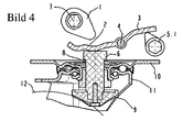
- the further actuating member may be formed with respect to the axis 4 of the other lever arm of the rocker arm 3 attacking further cam 5.1 ( FIG. 4 ).
- the cam 1 and the further cam 5.1 based on the rocker arm 3 on its different sides, namely front or rear are arranged.
- the function corresponds to the first embodiment.
Landscapes
- Engineering & Computer Science (AREA)
- Mechanical Engineering (AREA)
- Braking Arrangements (AREA)
Abstract
Description
Die Erfindung betrifft eine gattungsgemässe Rolle mit einer Bremseinrichtung nach dem Oberbegriff des Hauptanspruchs, also eine Rolle mit einer Bremseinrichtung mit einem in seiner Achsrichtung entgegen der Kraft einer Feder bewegbaren und die Lagerschalen mittig durchquerenden Bolzen, der an seinem rückwärtigen Ende zwecks Bremsung von zumindest einem Betätigungsglied betätigbar und dabei vorwärts in Achsrichtung so verschiebbar ist, dass er mit einem an seinem zu dem rückwärtigen Ende entgegengesetzt angeordneten vorderen Ende vorgesehehen Bremselement am Umfang eines in einer U-förmigen Gabel der Rolle gehalterten Rades zwecks Bremsung desselben zur Anlage kommt.The invention relates to a generic role with a braking device according to the preamble of the main claim, ie a roller with a braking device with a movable in its axial direction against the force of a spring and the bearing shells centrally traversing bolts at its rear end for the purpose of braking at least one actuator actuated and thereby forward in the axial direction is displaced so that it comes with a provided at its rear end opposite to the front end of the brake element on the circumference of a held in a U-shaped fork of the roll wheel for the purpose of braking the same comes to rest.
Solche Rollen sind an sich bekannt (
Von Nachteil bei dieser bekannten Ausführungsform ist die Tatsache, dass die Bremseinrichtung entweder nur als Feststellbremse oder aber nur als Fahrbremse ausgebildet ist, was den Einsatz der bekannten Rolle einschränkt.A disadvantage of this known embodiment is the fact that the braking device is designed either only as a parking brake or only as a driving brake, which limits the use of the known role.
Der Erfindung liegt deshalb die Aufgabe zugrunde, die Bremseinrichtung der gattungsgemässen Rolle zugleich sowohl als Feststellbremse als auch als Fahrbremse auszubilden.The invention is therefore the object of the brake device of the generic role at the same time both form a parking brake and as a driving brake.
Diese Aufgabe wird erfindungsgemäß bei einer gattungsgemässen Rolle nach dem Oberbegriff des Hauptanspruchs erfindungsgemäss durch dessen kennzeichnende Merkmale, also dadurch gelöst, dass die Bremseinrichtung einen um eine Achse kippbaren Hebel aufweist, dass das Betätigungsglied an einem Hebelarm des Hebels angreift, dass dieser beim Kippen um die Achse das rückwärtige Ende des Bolzens betätigt und dass ein an dem Hebel angreifendes weiteres Betätigungsglied vorgesehen ist.This object is achieved in a generic role according to the preamble of the main claim according to the invention by its characterizing features, ie by the fact that the braking device has a tiltable about an axis lever, that the actuating member acts on a lever arm of the lever, that this when tilting to the Axis actuates the rear end of the bolt and that a lever engaging on the other actuator is provided.
Es ist zwar eine gatungsgemässe Rolle nach dem Oberbegriff des Hauptanspruchs bekannt (
Hierdurch bedingt ist es erfindungsgemäss möglich, mittels zweier verschiedener Bremshebel, z.B. mittels eines mit dem Fuss zu betätigenden Feststellbremshebels und mittels eines Fahrbremshebels, z. B. in Form eines Handbremshebels über den Hebel auf ein und denselben Bolzen der Bremseinrichtung einzuwirken. Eine solche Rolle nach Lehre der Erfindung ist universeller einsetzbar.As a result, it is possible according to the invention, by means of two different brake levers, e.g. by means of a foot-operated parking brake lever and by means of a driving brake lever, z. B. in the form of a handbrake lever on the lever on one and the same pin of the braking device act. Such a role according to the teaching of the invention is universally applicable.
Weitere zweckmäßige Ausgestaltungen und Weiterbildung der Erfindung sind in den Unteransprüchen gekennzeichnet.Further expedient refinements and development of the invention are characterized in the subclaims.
Ein Ausführungsbeispiel der Erfindung wird nachfolgend unter Bezugnahme auf die Zeichnung näher erläutert. In dieser zeigt:
- Figur 1:
- eine erste Ausfürungsform der erfindungsgemässen Rolle, ungebremst, im schematischen Querschnitt
- Figur 2:
- die Rolle gemäss
Figur 1 - Figur 3:
- die Rolle gemäss
Figur 1 - Figur 4:
- eine zweite Ausfürungsform der Rolle, mit betätigter Fahrbremse, im schematischen Querschnitt.
- FIG. 1:
- a first Ausfürungsform the inventive roller, unbraked, in schematic cross section
- FIG. 2:
- the role according to
FIG. 1 , with activated parking brake - FIG. 3:
- the role according to
FIG. 1 , with actuated travel brake and - FIG. 4:
- a second Ausfürungsform the role, with operated drive brake, in schematic cross-section.
Die schematisch in
Die Lagerschalen 13 der Rolle sind mittels eines sie zentrisch durchgreifenden Aufnahmeteils, vorzugsweise einem Hohlniet zusammengehalten. Dieses und damit die Lagerschalen 13 sind mittig von einem Bolzen 6 durchquert, der in seiner Achsrichtung entgegen der Kraft einer Feder 8 bewegbar ist, welche den Bolzen 6 in seine ungebremste Lage schiebt. Der Bolzen 6 ist an seinem rückwärtigen Ende zwecks Bremsung von einem als Nocken 1 ausgebildeten Betätigungsglied betätigbar und dabei vorwärts in der Achsrichtung so verschiebbar (
Die Bremseinrichtung der Rolle weist einen um eine Achse 4 kippbaren, zwischen dem Nocken 1 und dem Bolzen 6 vorgesehenen und als zweiarmiger Kipphebel 3 ausgebildeten Hebel auf, dessen einerseits der Achse 4 befindlicher einer Hebelarm im Bereich des an ihm angreifenden Nockens 1 mit einer Gleitkontur 2 versehen ist und der von dem Bolzen 6 in seine Neutrallage (
Es ist ferner bei der ersten Ausführungsform ein weiteres als Seilzug 5.2 ausgebildetes Betätigungsglied vorgesehen, das an dem auf der anderen Seite der Achse 4 befindlichen anderen Hebelarm des Kipphebels 3 über eine Schraubenfeder 5.3 angreift, die in der ungebremsten Neutrallage des Kipphebels 3 gespannt und in der Übertotpunktblockierung des Nockens 1 bei betätigter Feststellbremse (
In alternativer -zweiter- Ausführungsform der Rolle kann das weitere Betätigungsglied an mit Bezug auf die Achse 4 dem anderen Hebelarm des Kipphebels 3 angreifender weiterer Nocken 5.1 ausgebildet sein (
Claims (12)
- Castor with a brake device comprising a pin (6) movable in its axial direction against the force of a spring (8) and passing through the centre of the bearing shells (13), the rear end of which can be activated by at least one activation element (1) for the purpose of braking and which can, in this context, be displaced forwards in the axial direction in such a manner that, with a brake element (9) provided at its front end disposed opposite to the rear end, it comes into contact with the periphery of a wheel mounted in a U-shaped fork (11) of the castor thereby braking the said wheel, wherein the brake device provides a lever (3) capable of being tilted about an axis (4),
characterised in that
the activation element (1) engages with a lever arm of the lever (3); that, when tilted about its axis (4), the lever activates the rear end of the pin (6); and that a further activation element (5.1, 5.2) engaging with the lever (3) is provided. - Castor according to claim 1,
characterised in that
the lever (3) is designed as two-arm tilting lever. - Castor according to claim 2,
characterised in that
the activation element engages with the one lever arm of the tilting lever (3), and the further activation element engages with the other lever arm of the tilting lever (3) disposed at the other end of the axis (4). - Castor according to any one of claims 1 to 3
characterised in that
the activation element is designed as a cam (1) engaging with the one lever arm of the tilting lever (3). - Castor according to claim 4,
characterised in that
the one lever arm of the tilting lever (3) is designed with a sliding contour in the region of the cam (1), with which it engages. - Castor according to claim 5,
characterised in that
the sliding contour of the one lever arm of the tilting lever (3) is designed with an indentation for a beyond-dead-centre blocking of the cam (1) thereby forming a locking brake. - Castor according to any one of claims 1 to 3,
characterised in that
the further activation element is designed as a further cam (5.1) engaging with the other lever arm of the tilting lever (3). - Castor according to claim 4,
characterised in that
the tilting lever (3) is provided between the cam (1) and the pin (6). - Castor according to claim 7 or 8,
characterised in that
the cam (1) and the further cam (5.1) are disposed at different ends of the tilting lever (3). - Castor according to any one of claims 1 to 3,
characterised in that
the further activation element is designed as a rope pull (5.2) engaging with the other lever arm of the tilting lever (3). - Castor according to claim 10,
characterised in that
the rope pull (5.2) engages with the other lever arm of the tilting lever (3) via a helical spring (5.3). - Castor according to claim 9,
characterised in that
the first lever arm of the tilting lever (3) is designed with a sliding contour in the region of the cam (1), with which it engages.
Applications Claiming Priority (2)
| Application Number | Priority Date | Filing Date | Title |
|---|---|---|---|
| DE200520006433 DE202005006433U1 (en) | 2005-04-21 | 2005-04-21 | Roller used on the lower side of rubbish containers comprises a braking unit having a tilting lever arranged on an actuating shaft with a further operating part arranged on the lever |
| DE200520006434 DE202005006434U1 (en) | 2005-04-21 | 2005-04-21 | Castor for use at lower side of container e.g. garbage container, has brake unit comprising lever, where actuator engages arm of lever and lever arm actuates rear end of bolt during tilting of lever and other actuator is provided at lever |
Publications (3)
| Publication Number | Publication Date |
|---|---|
| EP1714799A2 EP1714799A2 (en) | 2006-10-25 |
| EP1714799A3 EP1714799A3 (en) | 2007-03-07 |
| EP1714799B1 true EP1714799B1 (en) | 2008-07-23 |
Family
ID=36698771
Family Applications (1)
| Application Number | Title | Priority Date | Filing Date |
|---|---|---|---|
| EP06005353A Active EP1714799B1 (en) | 2005-04-21 | 2006-03-16 | Castor with brake device |
Country Status (3)
| Country | Link |
|---|---|
| EP (1) | EP1714799B1 (en) |
| AT (1) | ATE402028T1 (en) |
| DE (1) | DE502006001161D1 (en) |
Families Citing this family (2)
| Publication number | Priority date | Publication date | Assignee | Title |
|---|---|---|---|---|
| DE202009017461U1 (en) | 2009-12-17 | 2011-04-28 | Steinco Paul Vom Stein Gmbh | Brake and lock sensor and actuator for castors |
| DE102013206823B4 (en) * | 2013-04-16 | 2020-02-13 | Siemens Healthcare Gmbh | Braking device for a movement means designed for moving a medical examination and / or treatment device on a surface |
Family Cites Families (3)
| Publication number | Priority date | Publication date | Assignee | Title |
|---|---|---|---|---|
| GB695213A (en) * | 1950-10-20 | 1953-08-05 | Benford Ltd | Improvements in or relating to castors |
| DE3624089A1 (en) * | 1986-07-17 | 1988-01-21 | Schulte Soehne Gmbh Co A | Fixing device for castors in particular of rubbish containers |
| DE29708693U1 (en) * | 1997-05-15 | 1997-10-09 | Blickle Heinrich Gmbh Co Kg | role |
-
2006
- 2006-03-16 EP EP06005353A patent/EP1714799B1/en active Active
- 2006-03-16 AT AT06005353T patent/ATE402028T1/en active
- 2006-03-16 DE DE502006001161T patent/DE502006001161D1/en active Active
Also Published As
| Publication number | Publication date |
|---|---|
| ATE402028T1 (en) | 2008-08-15 |
| EP1714799A2 (en) | 2006-10-25 |
| EP1714799A3 (en) | 2007-03-07 |
| DE502006001161D1 (en) | 2008-09-04 |
Similar Documents
| Publication | Publication Date | Title |
|---|---|---|
| DE4032885A1 (en) | DISC BRAKE FOR VEHICLES, IN PARTICULAR ROAD VEHICLES | |
| EP0379065A1 (en) | Lockable castor | |
| DE3521794A1 (en) | ROLLER | |
| EP1714799B1 (en) | Castor with brake device | |
| CH642306A5 (en) | STEERING WHEEL WITH BRAKE DEVICE. | |
| DE112006001595T5 (en) | disc brake | |
| DE202005006433U1 (en) | Roller used on the lower side of rubbish containers comprises a braking unit having a tilting lever arranged on an actuating shaft with a further operating part arranged on the lever | |
| DE1257603C2 (en) | MECHANICAL ACTUATION DEVICE FOR DISC BRAKES, IN PARTICULAR FOR MOTOR VEHICLES | |
| DE102008015505B4 (en) | Pedestrian-controlled industrial truck | |
| EP0760324B1 (en) | Braking device for locking small vehicles like perambulators, wheelchairs, cleaning trolleys, shopping carts, by using a pedal | |
| DE2542122C3 (en) | Mechanical auxiliary release device for spring-loaded or combination cylinders | |
| DE10017032A1 (en) | Steering spindle locking device for automobile steering mechanism has spring tensioned by movement of locking element into locked position for spring-loaded movement into unlocked position | |
| DE202005006434U1 (en) | Castor for use at lower side of container e.g. garbage container, has brake unit comprising lever, where actuator engages arm of lever and lever arm actuates rear end of bolt during tilting of lever and other actuator is provided at lever | |
| DE10259448B4 (en) | castor | |
| DE3909629C2 (en) | ||
| DE3624089A1 (en) | Fixing device for castors in particular of rubbish containers | |
| DE102019123213B3 (en) | Roller attachment | |
| DE3018022A1 (en) | BRAKE DEVICE FOR VEHICLES | |
| DE19525722C2 (en) | Application device for a disc brake | |
| DE102010020669A1 (en) | Device for braking, steering and determining hand rim wheelchair, for physical handicap, has active unit provided with two wheel brake units, which are respectively arranged at left-sided and right-sided wheelchair wheels | |
| DE10006009C2 (en) | Four-wheel truck | |
| EP1842695B1 (en) | Brake drum | |
| DE2543930A1 (en) | ADJUSTMENT DEVICE FOR THE ACTUATING PISTON OF A PRESSURIZED BRAKE CYLINDER | |
| DE4329451C2 (en) | Brake system for vehicles | |
| DE60016539T2 (en) | Actuator for a ball-ramp brake |
Legal Events
| Date | Code | Title | Description |
|---|---|---|---|
| PUAI | Public reference made under article 153(3) epc to a published international application that has entered the european phase |
Free format text: ORIGINAL CODE: 0009012 |
|
| AK | Designated contracting states |
Kind code of ref document: A2 Designated state(s): AT BE BG CH CY CZ DE DK EE ES FI FR GB GR HU IE IS IT LI LT LU LV MC NL PL PT RO SE SI SK TR |
|
| AX | Request for extension of the european patent |
Extension state: AL BA HR MK YU |
|
| PUAL | Search report despatched |
Free format text: ORIGINAL CODE: 0009013 |
|
| AK | Designated contracting states |
Kind code of ref document: A3 Designated state(s): AT BE BG CH CY CZ DE DK EE ES FI FR GB GR HU IE IS IT LI LT LU LV MC NL PL PT RO SE SI SK TR |
|
| AX | Request for extension of the european patent |
Extension state: AL BA HR MK YU |
|
| 17P | Request for examination filed |
Effective date: 20070511 |
|
| AKX | Designation fees paid |
Designated state(s): AT CH DE IT LI |
|
| GRAP | Despatch of communication of intention to grant a patent |
Free format text: ORIGINAL CODE: EPIDOSNIGR1 |
|
| GRAS | Grant fee paid |
Free format text: ORIGINAL CODE: EPIDOSNIGR3 |
|
| GRAA | (expected) grant |
Free format text: ORIGINAL CODE: 0009210 |
|
| AK | Designated contracting states |
Kind code of ref document: B1 Designated state(s): AT CH DE IT LI |
|
| REG | Reference to a national code |
Ref country code: CH Ref legal event code: EP |
|
| REF | Corresponds to: |
Ref document number: 502006001161 Country of ref document: DE Date of ref document: 20080904 Kind code of ref document: P |
|
| REG | Reference to a national code |
Ref country code: CH Ref legal event code: NV Representative=s name: MANFRED SAEGER |
|
| PLBE | No opposition filed within time limit |
Free format text: ORIGINAL CODE: 0009261 |
|
| STAA | Information on the status of an ep patent application or granted ep patent |
Free format text: STATUS: NO OPPOSITION FILED WITHIN TIME LIMIT |
|
| 26N | No opposition filed |
Effective date: 20090424 |
|
| REG | Reference to a national code |
Ref country code: CH Ref legal event code: PFA Owner name: BLICKLE RAEDER + ROLLEN GMBH & CO.KG Free format text: BLICKLE RAEDER + ROLLEN GMBH & CO.KG#HEINRICH-BLICKLE-STRASSE 1#72348 ROSENFELD (DE) -TRANSFER TO- BLICKLE RAEDER + ROLLEN GMBH & CO.KG#HEINRICH-BLICKLE-STRASSE 1#72348 ROSENFELD (DE) |
|
| PGFP | Annual fee paid to national office [announced via postgrant information from national office to epo] |
Ref country code: CH Payment date: 20120416 Year of fee payment: 7 |
|
| PGFP | Annual fee paid to national office [announced via postgrant information from national office to epo] |
Ref country code: IT Payment date: 20120426 Year of fee payment: 7 |
|
| PGFP | Annual fee paid to national office [announced via postgrant information from national office to epo] |
Ref country code: AT Payment date: 20120420 Year of fee payment: 7 |
|
| REG | Reference to a national code |
Ref country code: CH Ref legal event code: PCAR Free format text: NEW ADDRESS: FELDGUEETLIWEG 130, 8706 MEILEN (CH) |
|
| REG | Reference to a national code |
Ref country code: CH Ref legal event code: PL |
|
| REG | Reference to a national code |
Ref country code: AT Ref legal event code: MM01 Ref document number: 402028 Country of ref document: AT Kind code of ref document: T Effective date: 20130316 |
|
| PG25 | Lapsed in a contracting state [announced via postgrant information from national office to epo] |
Ref country code: LI Free format text: LAPSE BECAUSE OF NON-PAYMENT OF DUE FEES Effective date: 20130331 Ref country code: CH Free format text: LAPSE BECAUSE OF NON-PAYMENT OF DUE FEES Effective date: 20130331 Ref country code: AT Free format text: LAPSE BECAUSE OF NON-PAYMENT OF DUE FEES Effective date: 20130316 |
|
| PG25 | Lapsed in a contracting state [announced via postgrant information from national office to epo] |
Ref country code: IT Free format text: LAPSE BECAUSE OF NON-PAYMENT OF DUE FEES Effective date: 20130316 |
|
| PGFP | Annual fee paid to national office [announced via postgrant information from national office to epo] |
Ref country code: DE Payment date: 20240321 Year of fee payment: 19 |