EP1714706A2 - Dosing pump and method for manufacturing such a filled dosing pump - Google Patents
Dosing pump and method for manufacturing such a filled dosing pump Download PDFInfo
- Publication number
- EP1714706A2 EP1714706A2 EP06007343A EP06007343A EP1714706A2 EP 1714706 A2 EP1714706 A2 EP 1714706A2 EP 06007343 A EP06007343 A EP 06007343A EP 06007343 A EP06007343 A EP 06007343A EP 1714706 A2 EP1714706 A2 EP 1714706A2
- Authority
- EP
- European Patent Office
- Prior art keywords
- container
- pump
- lid
- foil bag
- bag
- Prior art date
- Legal status (The legal status is an assumption and is not a legal conclusion. Google has not performed a legal analysis and makes no representation as to the accuracy of the status listed.)
- Withdrawn
Links
Images
Classifications
-
- B—PERFORMING OPERATIONS; TRANSPORTING
- B05—SPRAYING OR ATOMISING IN GENERAL; APPLYING FLUENT MATERIALS TO SURFACES, IN GENERAL
- B05B—SPRAYING APPARATUS; ATOMISING APPARATUS; NOZZLES
- B05B11/00—Single-unit hand-held apparatus in which flow of contents is produced by the muscular force of the operator at the moment of use
- B05B11/0005—Components or details
- B05B11/0062—Outlet valves actuated by the pressure of the fluid to be sprayed
- B05B11/0072—A valve member forming part of an outlet opening
-
- B—PERFORMING OPERATIONS; TRANSPORTING
- B05—SPRAYING OR ATOMISING IN GENERAL; APPLYING FLUENT MATERIALS TO SURFACES, IN GENERAL
- B05B—SPRAYING APPARATUS; ATOMISING APPARATUS; NOZZLES
- B05B11/00—Single-unit hand-held apparatus in which flow of contents is produced by the muscular force of the operator at the moment of use
- B05B11/0005—Components or details
- B05B11/0097—Means for filling or refilling the sprayer
-
- B—PERFORMING OPERATIONS; TRANSPORTING
- B05—SPRAYING OR ATOMISING IN GENERAL; APPLYING FLUENT MATERIALS TO SURFACES, IN GENERAL
- B05B—SPRAYING APPARATUS; ATOMISING APPARATUS; NOZZLES
- B05B11/00—Single-unit hand-held apparatus in which flow of contents is produced by the muscular force of the operator at the moment of use
- B05B11/01—Single-unit hand-held apparatus in which flow of contents is produced by the muscular force of the operator at the moment of use characterised by the means producing the flow
- B05B11/02—Membranes or pistons acting on the contents inside the container, e.g. follower pistons
- B05B11/026—Membranes separating the content remaining in the container from the atmospheric air to compensate underpressure inside the container
Definitions
- the present invention relates to a metering pump assembly comprising a container sealed to a manually operable pump which, in the unloaded condition, shuts off fluid communication between an outlet communicating outlet of the pump and the interior of the container through at least one check valve. Furthermore, the present invention relates to a method for producing a filled Dosierpumpenan extract and the use of such a Dosierpumpenan expect.
- From the DE 100 49 898 C2 is a delivery device for fluids known, with which, for example, liquid pharmaceuticals or cosmetics metered out of a container can be applied.
- the metering pump used for this purpose operates without air compensation, the liquid being accommodated inside the container in an environmentally sealed inner bag which collapses during emptying.
- valve in the discharge head of this known dispensing device is designed so that this indeed opens when the redesignate product flows under pressure from the pump in the discharge head, but is held by a spring in its closed position, as long as the product is not a sealing body against shifts the spring pressure, no residual air can be sucked through this discharge head to the outside. The extraction of the residual air is therefore only possible if the delivery head has not yet been placed on the pump.
- this entails the disadvantage that residual air always remains in the discharge head, which must be removed by a user from the discharge head before the first use by actuating the pump before the product can be removed. Since air is compressible and, for example, for the application of drugs with a pump stroke only small amounts of the product, e.g. about 28 mg, are often required this many pump strokes, which is perceived by users as unsatisfactory.
- Object of the present invention is in contrast to provide a metering pump arrangement of the type mentioned and method for producing a filled Dosierpumpenan Aunt, in which a complete suction of residual air from the container is facilitated.
- the container is sealed via a lid with a container facing, in particular concave recess relative to the pump, wherein the suction port of the pump for sucking gas in the container by the pump not or not at least protrudes substantially over the lid in the container.
- the gas in the container can be sucked by the pump, which open during suction by the negative pressure of the suction or the check valve (s) of the pump and thereby establish a fluid connection between the outlet port and the interior of the container.
- the check valves can be formed either by balls which are pressed, for example by compression springs against corresponding valve seats, or the check valves can also be formed by rubber lips or the like. Elastic elements in their unloaded Condition close a valve seat and, for example, can be lifted by fluid pressure of this.
- the suction of the residual air from the container can be carried out either in a state of Dosierpumpenanssen in which only the pump with eg. A check valve, but without an application head, which usually has a further check valve is provided on the container or the suction is carried out by the pump and the delivery head, ie through both check valves that open during aspiration.
- the discharge head or the like can be retrofitted to the pump.
- the outlet opening can therefore be formed in the sense of the present invention either by a nozzle or the like on the discharge head or by any opening through which the pump can be connected to an application head.
- the suction port of the pump according to the invention does not or not materially into the container.
- the residual air remaining in the container after filling of the container accumulates in its upper region formed by the recess, in which the pump is arranged.
- the suction must be as flush as possible with the inner wall of the container or at most only a few millimeters protrude into the interior of the container.
- a residual air bubble formed above the liquid can thus be sucked out of the container through the pump by the suction process described above, until the liquid taken up in the container is sucked through the suction opening. Since no air flows back into the container through the at least one check valve, the liquid received in the container can after suction the residual air in any position, ie directed upwards with the pump, upside down or laterally discharged by the pump from the container, the suction of the pump can always suck only liquid.
- liquid is intended to encompass all flowable substances that can be dispensed with such a pump. These may be viscous, pasty or gelatinous substances in addition to low viscosity.
- a suction cup When sucking the gas out of the container, a suction cup can be placed on the metering pump arrangement such that at least the outlet opening of the pump is surrounded by the suction cup.
- the suction cup is placed on the Dosierpumpenan Aunt that the suction cup is mounted on a wall of the container or an optionally associated with this lid and this sealingly surrounds the outside of the container or lid protruding part of the pump. It is then only necessary for sucking the residual air from the container, previously remove a possibly provided protective cap from the pump or the outlet opening.
- the negative pressure applied in the suction bell the residual air is then sucked out of the container, whereby the two check valves open by the suction pressure.
- the balls, sealing lips or the like against the elastic closing forces are lifted from its valve seat. After suction, the check valves close automatically, so that a re-entry of air into the container is avoided.
- the container has a particular flange-like lid, via which the container is sealed against the pump, wherein the suction port of the pump does not protrude or at least not substantially over the lid into the container.
- the lid can be formed of a stiffer material, so that it can be connected to a, for example. Stiffer enclosure or enclosure of the container with variable volume.
- the container Since the metering pump arrangement according to the invention operates without air compensation, the container must have a variable volume. This is possible in a particularly simple manner in that the container is formed from a collapsible foil or the like, for example as a foil bag. During the emptying of the container, it therefore contracts or folds up.
- the container is substantially associated with a rigid shell, which surrounds the container and with the pump, for example, via the lid is connectable.
- a vent opening is provided in the rigid shell, so that the collapse of the container in the shell is not hindered.
- the lid is provided with a peripheral edge, to which, for example, the film bag-like container is attached.
- the peripheral edge may be formed, for example, flange or stepped, wherein the film bag or the like container is preferably attached to the lower in use position edge region of the lid and sealingly applied.
- the use position is defined as a position in which the pump is located on the vertically upper side of the lid and the container, for example, designed as a foil bag is vertically below the lid and the pump.
- the rigid shell may be formed as a, at least on one end face open, in particular cylindrical container, said at least one open end side is closed by the lid.
- the metering pump arrangement Consequently, it is particularly easy to produce by placing the lid with the container attached thereto onto the stiffer shell.
- a seal may be provided between the stiffer shell and the lid.
- the concave recess in the cover for example, extends like a spherical cap, starting from a peripheral edge connected to the container to the suction opening.
- the depth of the recess of the attachable to the bag designed as a container edge of the lid to the suction port of the pump continuously, in particular curved increase.
- the configuration of the recess is not limited to a spherical cap-like shape, but the recess may also be conical, frusto-conical, pyramidal, truncated pyramid, stepped and / or designed with curved or straight faces.
- the recess is designed such that in use position of the preferably defined by the peripheral edge lowest point as possible adjacent to the container and in the use position vertically highest point in the region of the suction port of the pump. This makes it possible that any residual air accumulates in the container close to the suction port of the pump and thus can be easily sucked by the pump.
- the pump is a pressure chamber with a guided in this piston chamber, a first check valve which connects the pressure chamber to the container, and with a possibly a delivery head associated second check valve.
- the first check valve allows a flow from the container into the pressure chamber, if there is a lower pressure in this than in the container, while a flow in the opposite direction is basically blocked.
- the second check valve allows a flow from the pressure chamber into the environment, when the pressure in the pressure chamber exceeds a defined value, while a return flow, for example. Of ambient air in the pressure chamber through the second check valve is not possible.
- the check valves may be formed as balls, which, for example, are pressed elastically against a valve seat by a spring.
- the check valves are formed only by a sealing lip, which rests in the unloaded state on a valve seat and can be lifted by fluid pressure elastically from the valve seat.
- all non-return valves can be used for the metering pump according to the invention, which prevent backflow of air or the like.
- the metering pump In the container and allow the discharge of the liquid from the container when the pressure in the container or the pressure chamber is greater than in the pressure chamber or the environment is.
- a bellows-type pump or another suitable pumping device may be provided in a possibly removable from the pressure or piston chamber discharge head, the suction of the residual air can be done with or without the discharge head, since this only a check valve is required.
- the outlet opening may, for example, be formed by a nozzle for atomising the liquid contents of the container.
- the outlet opening in another way, for example, to deliver individual larger drops of a liquid through the metering pump arrangement.
- the dosing pump arrangement according to the invention is particularly suitable for dosing, dispensing, application or the like of liquid cosmetics and / or pharmaceuticals.
- a method for producing a filled metering pump arrangement comprises the following steps: filling a flowable product in a foil pouch, then closing the foil pouch by a manually operable pump which, in the unloaded state, shuts off fluid communication between an outlet port communicating with the environment and the interior of the foil pouch by at least one check valve and at least approximately complete removal of the pouch located in the foil pouch gases.
- the film bag in particular by means of a punch or the like. Compressed and thereby the gases contained in the foil bag are ejected from this through the pump and / or by a bypass channel bypassing them.
- the inventive ejection of the residual air by the pump itself or by a bypass channel can be achieved even with pumps or applicator heads, which do not allow extraction of the residual air, a complete venting of the film bag.
- the dosing pump arrangement is thus ready for operation and it can already be taken with the first pump stroke by a user, the flowable product.
- the ease of use of the metering pump assembly increases considerably.
- the inventive application of the residual air from the foil bag can be achieved particularly easily and quickly automated if the compression by means of a punch or alternatively by a pressure difference between the interior of the foil bag and the environment as a result of residual air suction by vacuum. As a result, the production cost of a filled metering pump arrangement according to the invention is reduced.
- the check valves can be formed either by balls which are pressed, for example, by compression springs against corresponding valve seats, or the check valves can also be formed by rubber lips or the like. Elastic elements which in their unloaded state a valve seat close and, for example, can be lifted by fluid pressure of this.
- the film bag is brought to remove the gases therein in a position in which the pump is arranged substantially vertically above the film bag.
- Collapsible foil bag is simplified when the residual air from one of the pump facing air bubble can escape through a suction, which is provided, for example, in the pump at its vertical lower end.
- the suction opening for ejecting the gases present in the film bag is provided on the pump in such a way that the suction opening does not project, or at least does not substantially protrude into the film bag.
- the foil bag is introduced before or after filling in a container which is stiffer in comparison to the foil bag and which is closed by the pump with the foil bag. In this case remains in the container at least one opening through which a stamp or the like. Introduced into the container in such a way that compresses the film bag in the container and thereby the gases contained in the foil bag from this by the pump and / or by one of these Bypass channel are ejected through.
- the film bag and / or the container are closed by a lid which is connected to the pump.
- the construction of the metering pump arrangement is therefore particularly compact and simple.
- At least one check valve of the pump may open and thereby establish a fluid connection between the outlet opening and the interior of the film bag.
- the balls, sealing lips or the like Against the elastic closing forces lifted from its valve seat.
- the check valves close automatically, so that a re-entry of air into the container is avoided.
- the discharge of the residual air from the container can be carried out either in a state of Dosierpumpenan Aunt in which only the pump with, for example.
- a check valve without an application head, which usually has a further check valve is provided on the container or the ejection is carried out by the pump and the delivery head, ie through both check valves which are opened.
- the discharge head or the like can be retrofitted to the pump.
- the outlet opening can therefore be formed in the sense of the present invention either by a nozzle or the like on the discharge head or by any opening through which the pump can be connected to an application head.
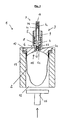
- a collapsible foil bag 2 as a container which is filled with a fluid, for example a liquid, pharmaceutical or cosmetic product.
- the film bag 2 is, as will be explained in more detail below, sealed to a pump 3, which in the illustrated embodiment comprises a pressure chamber 4 with a piston 5 sliding therein and two check valves 6 and 7, respectively.
- a spring 8 is provided in the pressure chamber 4, such that the piston 5 is acted upon in the figure upwards.
- the piston 5 has a central passage opening 9, through which a fluid can be pumped from the foil bag 2 into the environment.
- the first check valve 6 is connected such that this check valve 6 allows a flow from the foil bag 2 into the pressure chamber 4, when the spherical valve element 6a is lifted against the force of the valve spring 6b by a negative pressure in the pressure chamber 4 of its valve seat 6c. In the opposite direction, however, a flow from the pressure chamber 4 into the foil bag 2 through the first check valve 6 is blocked.
- the second check valve 7 is arranged so that at an overpressure in the pressure chamber 4 fluid can escape through the check valve 7 into the environment by the valve body 7a is lifted against the force of the valve spring 7b of its valve seat 7c. By contrast, a backflow of, for example, ambient air into the pressure chamber 4 is prevented by the check valve 7.
- the second check valve 7 is shown in the figure as part of the pump 3. Deviating from this, the second check valve may also be associated with a delivery head which can be fastened to the pump 3. In this case, the second valve does not have to be formed as shown in the figure but can also be like in the DE 101 08 486 A1 be designed described.
- the foil bag 2 is provided in the illustrated embodiment with an example. Stiffened cover 10, which seals the pump 3 against the foil bag 2.
- the cover 10 may be cast on the pump 3 or welded thereto.
- a peripheral edge of the collapsible foil bag 2 may be welded, glued or otherwise sealingly connected to an edge region of the rigid lid 10.
- the foil bag 2 is accommodated in, for example, a likewise rigid container (casing) 11, which is firmly or detachably connected to the lid 10.
- a bottom opening 12 is provided, so that the film bag 2 can freely expand or contract within the container 11, without this being hindered by an overpressure or underpressure in the container 11.
- the pump 3 has a lower in the figure suction port 13, which opens into the foil bag 2, and an upper outlet opening 14 in the figure, which communicates with the environment.
- the pump 3 and the suction opening 13 are arranged on the foil bag 2 or the cover 10 in such a way that the suction opening 13 in the embodiment shown does not or at most projects minimally beyond the lid 10 into the foil bag 2.
- a recess 15 is formed in the lid 10, in which an optionally existing in the foil bag 2 air bubble can accumulate with residual air.
- the depth of the recess 15 increases continuously from the edge of the lid 10 to the center of the lid 10, in which the suction port 13 of the pump 3 is arranged.
- the edge of the lid 10 protruding into the foil bag 2 is applied to the foil bag 2 and optionally connected to it.
- the metering pump assembly In the illustrated in the figure upright position of the metering pump assembly so collects the entire residual air inevitably in the vicinity of the suction port 13 of the pump 3 and can be discharged through this.
- a negative pressure is applied to the outlet opening 14, so that the valve bodies 6a and 6b rise against the force of the valve springs 6b and 7b from their valve seats 6c and 7c and the air through the suction opening 13 through the pump 3 to the outlet opening 14th can be sucked off.
- a punch 16 or the like Be introduced into the container 11, which compresses the film bag 2. Due to the overpressure in the container 11, the residual air is also expelled by the pump 3, whereby the valve body 6a and 7a stand against the force of the valve springs 6b and 7b of their valve seats 6c and 7c.
- the dispensing head As soon as fluid is sucked through the suction opening 13 and exits through the outlet opening 14, there is no residual air in the foil bag 2 and the pump 3 or the dispensing head.
- the two check valves 6 and 7 close again by the force of the valve springs 6b and 7b, so that no ambient air in the container 2 can flow back.
- the extraction of the residual air can, for example, take place in that a suction bell, not shown in the figure, at least the outlet opening 14 sealingly surrounds.
- the suction bell can also be placed on the lid 10, that the entire pump 3 is accommodated in the suction bell.
- the second check valve is provided in a discharge head (not shown in the figure), the residual air can be sucked out of the container 2 either before or after the placement of the delivery head.
- the first check valve 6 opens in the suction and prevents after the suction backflow of air into the container 2.
- both check valves 6, 7th are open with attached delivery head during the suction as described above, both check valves 6, 7th
- the central passage opening 9 of the pump 3 and the discharge head are filled after complete expulsion of the residual air from the metering pump assembly 1 with the product when the pressure in the container 11 remains established. In this way, a user can already remove the flowable product with the first pump stroke and does not have to first fill the pump 3 by several pump strokes before the first use of the dosing pump arrangement 1.
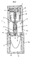
- FIG. 2 shows a further preferred embodiment of a metering pump arrangement 1 according to the invention, which is constructed similarly to the embodiment according to FIG. The function of this metering pump arrangement 1 also takes place in the manner described above with reference to FIG. Identical components are identified in this embodiment by the same reference numerals.
- the container (sleeve) accommodating the film bag 2 is formed in two parts with a partially double-walled container lower part 11a and a container upper part 11b fastened thereto by a latching connection, wherein the container upper part 11b receives the pump 3 and guides the piston 5.
- This construction allows a particularly easily produced by injection molding geometry of the container.
- the lower opening 12 in FIG. 2 for a piston or the like can be closed off after removal of the residual air from the foil bag 2 by a cover 17, in which a vent opening is again provided.
- the pump itself can by a protective cap 18, which on the container top 11 b can be plugged, are releasably closed after the residual air has been removed from the foil bag 2.
- the pressure chamber 4 forming body and the lid 10 are formed and adapted to each other, that these components are also connected by the engagement of the container upper part 11 b on the container base 11 a sealingly.
- a head 19 connected to the piston 5 is provided in the embodiment according to FIG. 2, which head is attached to the container top part 11 b.
- the stroke of the piston 5 is limited in this way.
- the second check valve 7 is provided, which has a nozzle for dispensing drops in the embodiment of Figure 2.
- the film bag 2 for removing the residual air for example, by means of a piston or the like. Compress, so as to expel the residual air from the foil bag and the pump 3.
Abstract
Description
Die vorliegende Erfindung betrifft eine Dosierpumpenanordnung mit einem Behälter, der abgedichtet mit einer manuell betätigbaren Pumpe verbunden ist, die im unbelasteten Zustand durch wenigstens ein Rückschlagventil eine Fluidverbindung zwischen einer mit der Umgebung in Verbindung stehenden Auslassöffnung der Pumpe und dem Inneren des Behälters absperrt. Weiter betrifft die vorliegende Erfindung ein Verfahren zur Herstellung einer befüllten Dosierpumpenanordnung sowie die Verwendung einer derartigen Dosierpumpenanordnung.The present invention relates to a metering pump assembly comprising a container sealed to a manually operable pump which, in the unloaded condition, shuts off fluid communication between an outlet communicating outlet of the pump and the interior of the container through at least one check valve. Furthermore, the present invention relates to a method for producing a filled Dosierpumpenanordnung and the use of such a Dosierpumpenanordnung.
Aus der
Das Befüllen derartiger Innenbeutel mit Flüssigkeiten, wie Pharmazeutika oder Kosmetika, erfolgt üblicherweise derart, dass in dem Innenbeutel Restluft verbleibt. Dies ist aus verschiedenen Gründen unerwünscht. So steht der Luftsauerstoff während der Lagerung stets mit der Flüssigkeit in Kontakt, was zu einer Verringerung der Aufbewahrungsdauer oder der Keimfreiheit der Flüssigkeit führt. Ein Abfüllen des Fluidbehälters in keimfreier Atmosphäre oder unter Schutzgas ist jedoch sehr aufwendig und teuer.The filling of such inner bags with liquids, such as pharmaceuticals or cosmetics, usually takes place in such a way that residual air remains in the inner bag. This is undesirable for several reasons. Thus, the atmospheric oxygen is always in contact with the liquid during storage, which leads to a reduction in the storage time or the sterility of the liquid. However, filling the fluid container in germ-free atmosphere or under protective gas is very complicated and expensive.
Zudem ist eine vollständige Entleerung des Beutels nur dann möglich, wenn in dem Innenbeutel nach der Befüllung keine Restluft verbleibt. Die Restluft in dem Innenbehälter wirkt sich auch dann störend aus, wenn die Abgabevorrichtung während der Betätigung nicht gerade gehalten wird. So kann durch die Pumpe bei nicht vollständig senkrechter Ausrichtung der Dosierpumpenanordnung Restluft angesaugt werden, die statt der Flüssigkeit aus dem Innenbeutel ausgebracht wird. Dies ist insbesondere bei der Verabreichung von Medikamenten, wie bspw. Nasen-, Augen- oder Ohrensprays, unerwünscht, bei denen eine Applikation mit exakt senkrecht gehaltener Abgabevorrichtung nur schwer möglich ist.In addition, complete emptying of the bag is only possible if no residual air remains in the inner bag after filling. The residual air in the Inner container also has a disturbing effect if the dispenser is not held straight during actuation. Thus, residual air can be sucked in by the pump when the orientation of the dosing pump arrangement is not completely vertical, which residual air is expelled from the inner bag instead of the liquid. This is particularly undesirable in the administration of drugs, such as nose, eye or ear sprays, in which an application with exactly vertical held dispenser is difficult.
In der
In der
Da das Ventil in dem Ausbringkopf dieser bekannten Abgabevorrichtung so gestaltet ist, dass dieses zwar öffnet, wenn das auszubringende Produkt unter Druck aus der Pumpe in den Ausbringkopf strömt, durch eine Feder jedoch in seiner geschlossenen Stellung gehalten wird, solange das Produkt nicht einen Dichtungskörper gegen den Federdruck verschiebt, kann durch diesen Ausbringkopf keine Restluft nach außen abgesaugt werden. Die Absaugung der Restluft ist folglich nur dann möglich, wenn der Ausbringkopf noch nicht auf die Pumpe aufgesetzt wurde. Dies bringt jedoch den Nachteil mit sich, dass in dem Ausbringkopf stets Restluft verbleibt, die von einem Benutzer vor dem ersten Gebrauch durch Betätigung der Pumpe aus dem Ausbringkopf entfernt werden muss, bevor das Produkt entnommen werden kann. Da Luft komprimierbar ist und bspw. für die Applikation von Medikamenten mit einem Pumpenhub nur geringe Mengen des Produkts, z.B. etwa 28 mg, ausgebracht werden, sind hierzu oftmals viele Pumpenhübe erforderlich, was von Benutzern als unbefriedigend empfunden wird.Since the valve in the discharge head of this known dispensing device is designed so that this indeed opens when the auszubringende product flows under pressure from the pump in the discharge head, but is held by a spring in its closed position, as long as the product is not a sealing body against shifts the spring pressure, no residual air can be sucked through this discharge head to the outside. The extraction of the residual air is therefore only possible if the delivery head has not yet been placed on the pump. However, this entails the disadvantage that residual air always remains in the discharge head, which must be removed by a user from the discharge head before the first use by actuating the pump before the product can be removed. Since air is compressible and, for example, for the application of drugs with a pump stroke only small amounts of the product, e.g. about 28 mg, are often required this many pump strokes, which is perceived by users as unsatisfactory.
Weiter ist aus der
Aus der
Aufgabe der vorliegenden Erfindung ist es demgegenüber, eine Dosierpumpenanordnung der eingangs genannten Art und Verfahren zur Herstellung einer befüllten Dosierpumpenanordnung zu schaffen, bei welchen ein vollständiges Absaugen von Restluft aus dem Behälter erleichtert wird.Object of the present invention is in contrast to provide a metering pump arrangement of the type mentioned and method for producing a filled Dosierpumpenanordnung, in which a complete suction of residual air from the container is facilitated.
Diese Aufgabe wird erfindungsgemäß im Wesentlichen dadurch gelöst, dass der Behälter über einen Deckel mit einer dem Behälter zugewandten, insbesondere konkaven Ausnehmung gegenüber der Pumpe abgedichtet ist, wobei die Ansaugöffnung der Pumpe zum Absaugen von in dem Behälter befindlichen Gas durch die Pumpe nicht oder zumindest nicht wesentlich über den Deckel in den Behälter hineinragt. Auf diese Weise kann das in dem Behälter befindliche Gas durch die Pumpe abgesaugt werden, wobei sich während des Absaugens durch den Unterdruck der Absaugvorrichtung das oder die Rückschlagventil(e) der Pumpe öffnen und dadurch eine Fluidverbindung zwischen der Auslassöffnung und dem Inneren des Behälters herstellen. Durch die Absaugung der Restluft durch die Pumpe selbst kann eine komplizierte Luftführung an der Pumpe vorbei vollständig entfallen. Auch der Aufbau der Pumpe kann besonders einfach gehalten werden. So können die Rückschlagventile entweder durch Kugeln gebildet werden, welche bspw. durch Druckfedern gegen entsprechende Ventilsitze gepresst werden, oder die Rückschlagventile können auch durch Gummilippen oder dgl. elastische Elemente gebildet werden, die in ihrem unbelasteten Zustand einen Ventilsitz verschließen und bspw. durch Fluiddruck von diesem aufgehoben werden können.This object is achieved essentially by the fact that the container is sealed via a lid with a container facing, in particular concave recess relative to the pump, wherein the suction port of the pump for sucking gas in the container by the pump not or not at least protrudes substantially over the lid in the container. In this way, the gas in the container can be sucked by the pump, which open during suction by the negative pressure of the suction or the check valve (s) of the pump and thereby establish a fluid connection between the outlet port and the interior of the container. By sucking the residual air through the pump itself can completely eliminate a complicated air flow past the pump. The construction of the pump can be kept very simple. Thus, the check valves can be formed either by balls which are pressed, for example by compression springs against corresponding valve seats, or the check valves can also be formed by rubber lips or the like. Elastic elements in their unloaded Condition close a valve seat and, for example, can be lifted by fluid pressure of this.
Das Absaugen der Restluft aus dem Behälter kann entweder in einem Zustand der Dosierpumpenanordnung erfolgen, in welchem nur die Pumpe mit bspw. einem Rückschlagventil jedoch ohne einen Ausbringkopf, der üblicherweise ein weiteres Rückschlagventil aufweist, an dem Behälter vorgesehen ist oder die Absaugung erfolgt durch die Pumpe und den Ausbringkopf, d.h. durch beide Rückschlagventile hindurch, die während des Absaugens geöffnet werden. Bei der erstgenannten Alternative kann der Ausbringkopf oder dgl. nachträglich an der Pumpe angebracht werden. Die Auslassöffnung kann im Sinne der vorliegenden Erfindung folglich entweder durch eine Düse oder dgl. an dem Ausbringkopf oder durch eine beliebige Öffnung gebildet werden, durch welche die Pumpe mit einem Ausbringkopf verbindbar ist.The suction of the residual air from the container can be carried out either in a state of Dosierpumpenanordnung in which only the pump with eg. A check valve, but without an application head, which usually has a further check valve is provided on the container or the suction is carried out by the pump and the delivery head, ie through both check valves that open during aspiration. In the former alternative, the discharge head or the like can be retrofitted to the pump. The outlet opening can therefore be formed in the sense of the present invention either by a nozzle or the like on the discharge head or by any opening through which the pump can be connected to an application head.
Durch die beispielsweise konkave Ausnehmung in dem Deckel ragt die Ansaugöffnung der Pumpe erfindungsgemäß nicht oder nicht wesentlich in den Behälter hinein. Die nach dem Befüllen des Behälters ggf. in diesem verbleibende Restluft sammelt sich in seinem durch die Ausnehmung gebildeten oberen Bereich, in welchem die Pumpe angeordnet ist. Um zu vermeiden, dass die Pumpe mit ihrer Ansaugöffnung bis in die Flüssigkeit hineinragt, was zwar zum Austragen der Flüssigkeit im Pumpbetrieb gewünscht ist, allerdings zum Absaugen der Restluft aus dem Behälter ungeeignet ist, muss die Ansaugöffnung möglichst bündig mit der Innenwand des Behälters abschließen oder allenfalls nur wenige Millimeter in das Innere des Behälters hineinragen. Eine über der Flüssigkeit gebildete Restluftblase kann so durch den oben beschriebenen Absaugvorgang aus dem Behälter durch die Pumpe hindurch abgesaugt werden, bis durch die Ansaugöffnung die im Behälter aufgenommene Flüssigkeit angesaugt wird. Da durch das wenigstens eine Rückschlagventil keine Luft in den Behälter zurückströmt, kann die in dem Behälter aufgenommene Flüssigkeit nach dem Absaugen der Restluft in einer beliebigen Stellung, d. h. mit der Pumpe nach oben gerichtet, auf dem Kopf stehend oder seitlich liegend durch die Pumpe aus dem Behälter ausgebracht werden, wobei die Ansaugöffnung der Pumpe stets nur Flüssigkeit ansaugen kann.By the example, concave recess in the lid, the suction port of the pump according to the invention does not or not materially into the container. The residual air remaining in the container after filling of the container accumulates in its upper region formed by the recess, in which the pump is arranged. To avoid that the pump projects with its suction into the liquid, which is indeed desired for discharging the liquid in the pumping operation, however, is unsuitable for sucking the residual air from the container, the suction must be as flush as possible with the inner wall of the container or at most only a few millimeters protrude into the interior of the container. A residual air bubble formed above the liquid can thus be sucked out of the container through the pump by the suction process described above, until the liquid taken up in the container is sucked through the suction opening. Since no air flows back into the container through the at least one check valve, the liquid received in the container can after suction the residual air in any position, ie directed upwards with the pump, upside down or laterally discharged by the pump from the container, the suction of the pump can always suck only liquid.
Der im Bezug auf die vorliegende Erfindung verwendete Ausdruck "Flüssigkeit" soll hier sämtliche fließfähigen Substanzen umfassen, die mit einer derartigen Pumpe ausgebracht werden können. Dies können neben dünnflüssigen auch zähflüssige, pastöse oder gelartige Substanzen sein.As used herein, the term "liquid" is intended to encompass all flowable substances that can be dispensed with such a pump. These may be viscous, pasty or gelatinous substances in addition to low viscosity.
Beim Absaugen des Gases aus dem Behälter kann eine Saugglocke derart auf die Dosierpumpenanordnung aufgesetzt werden, dass zumindest die Auslassöffnung der Pumpe von der Saugglocke umgeben ist. Vorzugsweise wird die Saugglocke so auf die Dosierpumpenanordnung aufgesetzt, dass die Saugglocke an einer Wand des Behälters bzw. eines ggf. mit diesem verbundenen Deckels aufgesetzt ist und hierbei den nach außen über den Behälter bzw. Deckel hervorstehenden Teil der Pumpe abdichtend umgreift. Es ist dann zum Absaugen der Restluft aus dem Behälter lediglich erforderlich, zuvor eine ggf. vorgesehene Schutzkappe von der Pumpe bzw. der Auslassöffnung abzunehmen. Durch den in der Absaugglocke angelegten Unterdruck wird dann die Restluft aus dem Behälter gesaugt, wobei sich die beiden Rückschlagventile durch den Absaugdruck öffnen. Hierbei werden die Kugeln, Dichtlippen oder dgl. entgegen den elastischen Schließkräften von ihrem Ventilsitz abgehoben. Nach dem Absaugen schließen die Rückschlagventile selbsttätig, so dass ein erneutes Eindringen von Luft in den Behälter vermieden wird.When sucking the gas out of the container, a suction cup can be placed on the metering pump arrangement such that at least the outlet opening of the pump is surrounded by the suction cup. Preferably, the suction cup is placed on the Dosierpumpenanordnung that the suction cup is mounted on a wall of the container or an optionally associated with this lid and this sealingly surrounds the outside of the container or lid protruding part of the pump. It is then only necessary for sucking the residual air from the container, previously remove a possibly provided protective cap from the pump or the outlet opening. By the negative pressure applied in the suction bell, the residual air is then sucked out of the container, whereby the two check valves open by the suction pressure. Here, the balls, sealing lips or the like. Against the elastic closing forces are lifted from its valve seat. After suction, the check valves close automatically, so that a re-entry of air into the container is avoided.
Nach einer bevorzugten Ausführungsform der Erfindung weist der Behälter einen insbesondere flanschartigen Deckel auf, über den der Behälter gegenüber der Pumpe abgedichtet ist, wobei die Ansaugöffnung der Pumpe nicht oder zumindest nicht wesentlich über den Deckel in den Behälter hineinragt. Der Deckel kann dabei aus einem steiferen Material gebildet sein, so dass er mit einer bspw. ebenfalls steiferen Umhüllung oder Einhausung des Behälters mit veränderbarem Volumen verbindbar ist.According to a preferred embodiment of the invention, the container has a particular flange-like lid, via which the container is sealed against the pump, wherein the suction port of the pump does not protrude or at least not substantially over the lid into the container. The lid can be formed of a stiffer material, so that it can be connected to a, for example. Stiffer enclosure or enclosure of the container with variable volume.
Da die erfindungsgemäße Dosierpumpenanordnung luftausgleichsfrei arbeitet, muss der Behälter ein veränderbares Volumen aufweisen. Dies ist auf besonders einfache Weise dadurch möglich, dass der Behälter aus einer kollabierbaren Folie oder dgl. beispielsweise als Folienbeutel gebildet ist. Während des Entleerens des Behälters zieht oder faltet sich dieser folglich zusammen.Since the metering pump arrangement according to the invention operates without air compensation, the container must have a variable volume. This is possible in a particularly simple manner in that the container is formed from a collapsible foil or the like, for example as a foil bag. During the emptying of the container, it therefore contracts or folds up.
Zur leichteren Handhabbarkeit der Dosierpumpenanordnung, insbesondere zum Ergreifen der Anordnung während der Betätigung der Pumpe, wird es bevorzugt, wenn dem Behälter im Wesentlichen eine steife Hülle zugeordnet ist, die den Behälter umgreift und mit der Pumpe bspw. über den Deckel verbindbar ist. Hierbei ist in der steifen Hülle eine Entlüftungsöffnung vorzusehen, so dass das Kollabieren des Behälters in der Hülle nicht behindert wird.For ease of handling the Dosierpumpenanordnung, in particular for gripping the assembly during actuation of the pump, it is preferred that the container is substantially associated with a rigid shell, which surrounds the container and with the pump, for example, via the lid is connectable. Here, a vent opening is provided in the rigid shell, so that the collapse of the container in the shell is not hindered.
Nach einer bevorzugten Ausführungsform der Erfindung ist der Deckel mit einem umlaufenden Rand versehen, an welchem der beispielsweise folienbeutelartige Behälter befestigt ist. Der umlaufende Rand kann dabei zum Beispiel flanschartig oder abgestuft ausgebildet sein, wobei der Folienbeutel oder dergleichen Behälter vorzugsweise an dem in Benutzungsstellung unteren Randbereich des Deckels befestigt ist bzw. dichtend anliegt. Die Benutzungsstellung ist dabei als eine Stellung definiert, in welcher sich die Pumpe auf der vertikal oberen Seite des Deckels befindet und der beispielsweise als Folienbeutel ausgebildete Behälter sich vertikal unterhalb des Deckels und der Pumpe befindet.According to a preferred embodiment of the invention, the lid is provided with a peripheral edge, to which, for example, the film bag-like container is attached. The peripheral edge may be formed, for example, flange or stepped, wherein the film bag or the like container is preferably attached to the lower in use position edge region of the lid and sealingly applied. The use position is defined as a position in which the pump is located on the vertically upper side of the lid and the container, for example, designed as a foil bag is vertically below the lid and the pump.
Die steife Hülle kann als ein zumindest auf einer Stirnseite offener, insbesondere zylindrischer Behälter ausgebildet sein, wobei diese zumindest eine offene Stirnseite durch den Deckel verschließbar ist. Die Dosierpumpenanordnung lässt sich folglich besonders einfach dadurch herstellen, dass der Deckel mit dem daran befestigten Behälter auf die steifere Hülle aufgesetzt wird. Gegebenenfalls kann zwischen der steiferen Hülle und dem Deckel eine Dichtung vorgesehen sein.The rigid shell may be formed as a, at least on one end face open, in particular cylindrical container, said at least one open end side is closed by the lid. The metering pump arrangement Consequently, it is particularly easy to produce by placing the lid with the container attached thereto onto the stiffer shell. Optionally, a seal may be provided between the stiffer shell and the lid.
Es wird bevorzugt, wenn die konkave Ausnehmung in dem Deckel sich beispielsweise kugelkappenartig ausgehend von einem mit dem Behälter verbundenen umlaufenden Rand zu der Ansaugöffnung hin erstreckt. So kann die Tiefe der Ausnehmung von dem an dem als Folienbeutel ausgebildeten Behälter anlegbaren Rand des Deckels zu der Ansaugöffnung der Pumpe kontinuierlich, insbesondere gewölbt, zunehmen. Die Ausgestaltung der Ausnehmung ist dabei nicht auf eine kugelkappenartige Form beschränkt, vielmehr kann die Ausnehmung auch kegelförmig, kegelstumpfförmig, pyramidenförmig, pyramidenstumpfförmig, stufenförmig und/oder mit gekrümmten oder geraden Teilflächen gestaltet sein. Wesentlich ist dabei, dass die Ausnehmung derart gestaltet ist, dass sich in Benutzungsstellung der vorzugsweise durch den umlaufenden Rand definierte tiefste Punkt möglichst anliegend an den Behälter und der in der Benutzungsposition vertikal höchste Punkt im Bereich der Ansaugöffnung der Pumpe befindet. Hierdurch ist es möglich, dass sich etwaige Restluft in dem Behälter nahe an der Ansaugöffnung der Pumpe ansammelt und somit leicht durch die Pumpe abgesaugt werden kann.It is preferred if the concave recess in the cover, for example, extends like a spherical cap, starting from a peripheral edge connected to the container to the suction opening. Thus, the depth of the recess of the attachable to the bag designed as a container edge of the lid to the suction port of the pump continuously, in particular curved, increase. The configuration of the recess is not limited to a spherical cap-like shape, but the recess may also be conical, frusto-conical, pyramidal, truncated pyramid, stepped and / or designed with curved or straight faces. It is essential that the recess is designed such that in use position of the preferably defined by the peripheral edge lowest point as possible adjacent to the container and in the use position vertically highest point in the region of the suction port of the pump. This makes it possible that any residual air accumulates in the container close to the suction port of the pump and thus can be easily sucked by the pump.
Es wird bevorzugt, wenn die Pumpe eine Druckkammer mit einem in dieser geführten Kolbenkammer ein erstes Rückschlagventil, welches die Druckkammer mit dem Behälter verbindet, und mit einem ggf. einem Ausbringkopf zugeordneten zweiten Rückschlagventil versehen ist. Das erste Rückschlagventil gestattet dabei eine Strömung aus dem Behälter in die Druckkammer, wenn in dieser ein niedrigerer Druck als in dem Behälter herrscht, während eine Strömung in entgegengesetzter Richtung grundsätzlich gesperrt ist. Entsprechend gestattet das zweite Rückschlagventil eine Strömung aus der Druckkammer in die Umgebung, wenn der Druck in der Druckkammer einen definierten Wert übersteigt, während eine Rückströmung bspw. von Umgebungsluft in die Druckkammer durch das zweite Rückschlagventil nicht möglich ist. Die Rückschlagventile können als Kugeln ausgebildet sein, welche bspw. durch eine Feder elastisch gegen einen Ventilsitz gepresst werden. Alternativ hierzu ist es auch möglich, dass die Rückschlagventile lediglich durch eine Dichtlippe gebildet sind, welche im unbelasteten Zustand auf einem Ventilsitz aufliegt und durch Fluiddruck elastisch von dem Ventilsitz abgehoben werden kann. Grundsätzlich können für die erfindungsgemäße Dosierpumpenanordnung sämtliche Rückschlagventile eingesetzt werden, die ein Zurückströmen von Luft oder dgl. in den Behälter unterbinden und das Ausbringen der Flüssigkeit aus dem Behälter ermöglichen, wenn der Druck in dem Behälter bzw. der Druckkammer größer als in der Druckkammer bzw. der Umgebung ist. Alternativ zu der beschriebenen Ausgestaltung der Pumpe mit einem Kolben und einer Druckkammer ist es auch möglich, eine blasebalgartige Pumpe oder eine andere geeignete Pumpvorrichtung vorzusehen. Das zweite Rückschlagventil kann in einem ggf. von der Druck- oder Kolbenkammer abnehmbaren Ausbringkopf vorgesehen sein, wobei das Absaugen der Restluft mit oder ohne den Ausbringkopf erfolgen kann, da hierzu lediglich ein Rückschlagventil erforderlich ist.It is preferred if the pump is a pressure chamber with a guided in this piston chamber, a first check valve which connects the pressure chamber to the container, and with a possibly a delivery head associated second check valve. The first check valve allows a flow from the container into the pressure chamber, if there is a lower pressure in this than in the container, while a flow in the opposite direction is basically blocked. Accordingly, the second check valve allows a flow from the pressure chamber into the environment, when the pressure in the pressure chamber exceeds a defined value, while a return flow, for example. Of ambient air in the pressure chamber through the second check valve is not possible. The check valves may be formed as balls, which, for example, are pressed elastically against a valve seat by a spring. Alternatively, it is also possible that the check valves are formed only by a sealing lip, which rests in the unloaded state on a valve seat and can be lifted by fluid pressure elastically from the valve seat. Basically, all non-return valves can be used for the metering pump according to the invention, which prevent backflow of air or the like. In the container and allow the discharge of the liquid from the container when the pressure in the container or the pressure chamber is greater than in the pressure chamber or the environment is. As an alternative to the described embodiment of the pump with a piston and a pressure chamber, it is also possible to provide a bellows-type pump or another suitable pumping device. The second check valve may be provided in a possibly removable from the pressure or piston chamber discharge head, the suction of the residual air can be done with or without the discharge head, since this only a check valve is required.
In Abhängigkeit des Einsatzzweckes der Dosierpumpenanordnung kann die Auslassöffnung bspw. durch eine Düse zum Zerstäuben des flüssigen Inhalts des Behälters gebildet sein. Es ist jedoch auch möglich, die Auslassöffnung in anderer Weise zu gestalten, um etwa durch die Dosierpumpenanordnung einzelne größere Tropfen einer Flüssigkeit abzugeben. Die erfindungsgemäße Dosierpumpenanordnung eignet sich insbesondere zum Dosieren, Ausbringen, zur Applikation oder dgl. von flüssigen Kosmetika und/oder Pharmazeutika.Depending on the intended use of the metering pump arrangement, the outlet opening may, for example, be formed by a nozzle for atomising the liquid contents of the container. However, it is also possible to design the outlet opening in another way, for example, to deliver individual larger drops of a liquid through the metering pump arrangement. The dosing pump arrangement according to the invention is particularly suitable for dosing, dispensing, application or the like of liquid cosmetics and / or pharmaceuticals.
Ein erfindungsgemäßes Verfahren zur Herstellung einer befüllten Dosierpumpenanordnung umfasst die folgenden Schritte: Einfüllen eines fließfähigen Produkts in einen Folienbeutel, anschließendes Verschließen des Folienbeutels durch eine manuell betätigbare Pumpe, die im unbelasteten Zustand durch wenigstens ein Rückschlagventil eine Fluidverbindung zwischen einer mit der Umgebung in Verbindung stehenden Auslassöffnung und dem Inneren des Folienbeutels absperrt, und zumindest näherungsweise vollständiges Entfernen der in dem Folienbeutel befindlichen Gase. Dabei wird der Folienbeutel insbesondere mittels eines Stempels oder dgl. komprimiert und hierdurch werden die in dem Folienbeutel befindlichen Gase aus diesem durch die Pumpe und/oder durch einen diese umgehenden Bypasskanal hindurch ausgestoßen.A method according to the invention for producing a filled metering pump arrangement comprises the following steps: filling a flowable product in a foil pouch, then closing the foil pouch by a manually operable pump which, in the unloaded state, shuts off fluid communication between an outlet port communicating with the environment and the interior of the foil pouch by at least one check valve and at least approximately complete removal of the pouch located in the foil pouch gases. In this case, the film bag in particular by means of a punch or the like. Compressed and thereby the gases contained in the foil bag are ejected from this through the pump and / or by a bypass channel bypassing them.
Durch das erfindungsgemäße Ausstoßen der Restluft durch die Pumpe selbst bzw. durch einen Bypasskanal kann auch bei Pumpen oder Ausbringköpfen, die ein Absaugen der Restluft nicht ermöglichen, eine vollständige Entlüftung des Folienbeutels erreicht werden. Die Dosierpumpenanordnung ist somit betriebsfertig und es kann bereits mit dem ersten Pumpenhub durch einen Benutzer das fließfähige Produkt entnommen werden. Hierdurch steigt der Bedienungskomfort der Dosierpumpenanordnung erheblich. Zudem lässt sich das erfindungsgemäße Ausbringen der Restluft aus dem Folienbeutel besonders einfach und schnell automatisierbar erreichen, wenn die Komprimierung mittels eines Stempels oder alternativ durch einen Druckunterschied zwischen dem Inneren des Folienbeutels und der Umgebung infolge einer Restluftabsaugung durch Unterdruck erfolgt. Hierdurch wird der Produktionsaufwand einer erfindungsgemäßen befüllten Dosierpumpenanordnung reduziert.By the inventive ejection of the residual air by the pump itself or by a bypass channel can be achieved even with pumps or applicator heads, which do not allow extraction of the residual air, a complete venting of the film bag. The dosing pump arrangement is thus ready for operation and it can already be taken with the first pump stroke by a user, the flowable product. As a result, the ease of use of the metering pump assembly increases considerably. In addition, the inventive application of the residual air from the foil bag can be achieved particularly easily and quickly automated if the compression by means of a punch or alternatively by a pressure difference between the interior of the foil bag and the environment as a result of residual air suction by vacuum. As a result, the production cost of a filled metering pump arrangement according to the invention is reduced.
Auch der Aufbau der Pumpe kann besonders einfach gehalten werden. So können die Rückschlagventile entweder durch Kugeln gebildet werden, welche bspw. durch Druckfedern gegen entsprechende Ventilsitze gepresst werden, oder die Rückschlagventile können auch durch Gummilippen oder dgl. elastische Elemente gebildet werden, die in ihrem unbelasteten Zustand einen Ventilsitz verschließen und bspw. durch Fluiddruck von diesem aufgehoben werden können.The construction of the pump can be kept very simple. Thus, the check valves can be formed either by balls which are pressed, for example, by compression springs against corresponding valve seats, or the check valves can also be formed by rubber lips or the like. Elastic elements which in their unloaded state a valve seat close and, for example, can be lifted by fluid pressure of this.
Vorzugsweise wird der Folienbeutel zum Entfernen der in diesem befindlichen Gase in eine Position gebracht, in welcher die Pumpe im Wesentlichen vertikal oberhalb des Folienbeutels angeordnet ist. Mit anderen Worten wird das Entleeren der Restluft aus dem bspw. kollabierbaren Folienbeutel vereinfacht, wenn die Restluft aus einer der Pumpe zugewandten Luftblase durch eine Ansaugöffnung entweichen kann, die bspw. in der Pumpe an ihrem vertikal unteren Ende vorgesehen ist. Hierbei wird es bevorzugt, dass die Ansaugöffnung zum Ausstoßen der in dem Folienbeutel befindlichen Gase an der Pumpe derart vorgesehen ist, dass die Ansaugöffnung nicht oder zumindest nicht wesentlich in den Folienbeutel hineinragt.Preferably, the film bag is brought to remove the gases therein in a position in which the pump is arranged substantially vertically above the film bag. In other words, the emptying of the residual air from the example. Collapsible foil bag is simplified when the residual air from one of the pump facing air bubble can escape through a suction, which is provided, for example, in the pump at its vertical lower end. In this case, it is preferred that the suction opening for ejecting the gases present in the film bag is provided on the pump in such a way that the suction opening does not project, or at least does not substantially protrude into the film bag.
In Weiterbildung des Erfindungsgedankens ist es vorgesehen, dass der Folienbeutel vor oder nach dem Befüllen in einen im Vergleich zu dem Folienbeutel steiferen Behälter eingebracht wird, der mit dem Folienbeutel durch die Pumpe verschlossen wird. Dabei verbleibt in dem Behälter wenigstens eine Öffnung, durch welchen ein Stempel oder dgl. derart in den Behälter einführbar ist, dass der Folienbeutel in dem Behälter komprimiert und hierdurch die in dem Folienbeutel befindlichen Gase aus diesem durch die Pumpe und/oder durch einen diese umgehenden Bypasskanal hindurch ausgestoßen werden.In a further development of the inventive concept, it is provided that the foil bag is introduced before or after filling in a container which is stiffer in comparison to the foil bag and which is closed by the pump with the foil bag. In this case remains in the container at least one opening through which a stamp or the like. Introduced into the container in such a way that compresses the film bag in the container and thereby the gases contained in the foil bag from this by the pump and / or by one of these Bypass channel are ejected through.
Hierbei wird es bevorzugt, wenn der Folienbeutel und/oder der Behälter durch einen Deckel verschlossen werden, der mit der Pumpe verbunden ist. der Aufbau der Dosierpumpenanordnung ist dadurch besonders kompakt und einfach.In this case, it is preferred if the film bag and / or the container are closed by a lid which is connected to the pump. the construction of the metering pump arrangement is therefore particularly compact and simple.
Während des Ausstoßens des Restgases kann sich wenigstens ein Rückschlagventil der Pumpe öffnen und dadurch eine Fluidverbindung zwischen der Auslassöffnung und dem Inneren des Folienbeutels herstellen. Hierbei werden die Kugeln, Dichtlippen oder dgl. entgegen den elastischen Schließkräften von ihrem Ventilsitz abgehoben. Nach dem Ausstoßen der Restluft schließen die Rückschlagventile selbsttätig, so dass ein erneutes Eindringen von Luft in den Behälter vermieden wird. Das Ausstoßen der Restluft aus dem Behälter kann entweder in einem Zustand der Dosierpumpenanordnung erfolgen, in welchem nur die Pumpe mit bspw. einem Rückschlagventil jedoch ohne einen Ausbringkopf, der üblicherweise ein weiteres Rückschlagventil aufweist, an dem Behälter vorgesehen ist oder das Ausstoßen erfolgt durch die Pumpe und den Ausbringkopf, d.h. durch beide Rückschlagventile hindurch, die dabei geöffnet werden. Bei der erstgenannten Alternative kann der Ausbringkopf oder dgl. nachträglich an der Pumpe angebracht werden. Die Auslassöffnung kann im Sinne der vorliegenden Erfindung folglich entweder durch eine Düse oder dgl. an dem Ausbringkopf oder durch eine beliebige Öffnung gebildet werden, durch welche die Pumpe mit einem Ausbringkopf verbindbar ist.During discharge of the residual gas, at least one check valve of the pump may open and thereby establish a fluid connection between the outlet opening and the interior of the film bag. Here are the balls, sealing lips or the like. Against the elastic closing forces lifted from its valve seat. After discharging the residual air, the check valves close automatically, so that a re-entry of air into the container is avoided. The discharge of the residual air from the container can be carried out either in a state of Dosierpumpenanordnung in which only the pump with, for example. A check valve without an application head, which usually has a further check valve is provided on the container or the ejection is carried out by the pump and the delivery head, ie through both check valves which are opened. In the former alternative, the discharge head or the like can be retrofitted to the pump. The outlet opening can therefore be formed in the sense of the present invention either by a nozzle or the like on the discharge head or by any opening through which the pump can be connected to an application head.
Weiterbildungen Vorteile und Anwendungsmöglichkeiten der Erfindung ergeben sich auch aus der nachfolgenden Beschreibung von Ausführungsbeispielen und der Zeichnung. Dabei bilden alle beschriebenen und/oder bildlich dargestellten Merkmale für sich oder in beliebiger Kombination den Gegenstand der Erfindung, unabhängig von ihrer Zusammenfassung in den Ansprüchen oder deren Rückbeziehung.Further developments and advantages of the invention will become apparent from the following description of exemplary embodiments and the drawings. All described and / or illustrated features alone or in any combination form the subject matter of the invention, regardless of their combination in the claims or their dependency.
Es zeigen schematisch:
Figur 1- in Schnittansicht eine Dosierpumpenanordnung nach einer ersten Ausführungsform der Erfindung und
Figur 2- in Schnittansicht eine Dosierpumpenanordnung nach einer zweiten Ausführungsform der Erfindung.
- FIG. 1
- in sectional view a Dosierpumpenanordnung according to a first embodiment of the invention and
- FIG. 2
- in sectional view a Dosierpumpenanordnung according to a second embodiment of the invention.
Die Dosierpumpenanordnung 1 nach Figur 1 weist einen kollabierbaren Folienbeutel 2 als Behälter auf, der mit einem Fluid, bspw. einem flüssigen, pharmazeutischen oder kosmetischen Produkt, befüllt ist. Der Folienbeutel 2 ist, wie unten näher erläutert wird, abgedichtet mit einer Pumpe 3 verbunden, die in der gezeigten Ausführungsform eine Druckkammer 4 mit einem darin gleitenden Kolben 5 und zwei Rückschlagventilen 6 bzw. 7 umfasst.1 has a
In der Druckkammer 4 ist eine Feder 8 derart vorgesehen, dass der Kolben 5 in der Figur nach oben beaufschlagt wird. Der Kolben 5 weist eine zentrale Durchgangsöffnung 9 auf, durch welche ein Fluid aus dem Folienbeutel 2 in die Umgebung gepumpt werden kann.In the
Hierzu ist das erste Rückschlagventil 6 derart geschaltet, dass dieses Rückschlagventil 6 eine Strömung aus dem Folienbeutel 2 in die Druckkammer 4 gestattet, wenn das kugelförmige Ventilelement 6a gegen die Kraft der Ventilfeder 6b durch einen Unterdruck in der Druckkammer 4 von seinem Ventilsitz 6c abgehoben wird. In entgegengesetzter Richtung wird eine Strömung aus der Druckkammer 4 in den Folienbeutel 2 durch das erste Rückschlagventil 6 jedoch gesperrt.For this purpose, the first check valve 6 is connected such that this check valve 6 allows a flow from the
Weiter ist das zweite Rückschlagventil 7 so angeordnet, dass bei einem Überdruck in der Druckkammer 4 Fluid durch das Rückschlagventil 7 in die Umgebung entweichen kann, indem der Ventilkörper 7a gegen die Kraft der Ventilfeder 7b von seinem Ventilsitz 7c abgehoben wird. Dagegen ist ein Zurückströmen von bspw. Umgebungsluft in die Druckkammer 4 durch das Rückschlagventil 7 unterbunden. Das zweite Rückschlagventil 7 ist in der Figur als ein Bestandteil der Pumpe 3 dargestellt. Abweichend hiervon kann das zweite Rückschlagventil auch einem Ausbringkopf zugeordnet sein, der an der Pumpe 3 befestigbar ist. Dabei muss das zweite Ventil nicht wie in der Figur dargestellt ausgebildet sein, sondern kann auch wie in der
Der Folienbeutel 2 ist in der dargestellten Ausführungsform mit einem bspw. versteiften Deckel 10 versehen, welcher die Pumpe 3 gegenüber dem Folienbeutel 2 abdichtet. Hierzu kann der Deckel 10 an die Pumpe 3 angegossen oder mit dieser verschweißt sein. In gleicher Weise kann ein umlaufender Rand des kollabierbaren Folienbeutel 2 mit einem Randbereich des steifen Deckels 10 verschweißt, verklebt oder in anderer geeigneter Weise abdichtend verbunden sein. Der Folienbeutel 2 ist in einem bspw. ebenfalls steifen Behälter (Hülle) 11 aufgenommen, die mit dem Deckel 10 fest oder lösbar verbunden ist. In dem Behälter 11 ist eine Bodenöffnung 12 vorgesehen, so dass sich der Folienbeutel 2 innerhalb des Behälters 11 frei entfalten oder zusammenziehen kann, ohne dass dies durch einen Über- oder Unterdruck in dem Behälter 11 behindert würde.The
Die Pumpe 3 weist eine in der Figur untere Ansaugöffnung 13, die in den Folienbeutel 2 mündet, und eine in der Figur obere Auslassöffnung 14 auf, die mit der Umgebung in Verbindung steht. Die Pumpe 3 und die Ansaugöffnung 13 sind dabei derart an dem Folienbeutel 2 bzw. dem Deckel 10 angeordnet, dass die Ansaugöffnung 13 in der gezeigten Ausführungsform nicht bzw. allenfalls minimal über den Deckel 10 hinaus in den Folienbeutel 2 hineinragt. Dabei ist in dem Deckel 10 eine Vertiefung 15 ausgebildet, in welcher sich eine ggf. in dem Folienbeutel 2 vorhandene Luftblase mit Restluft ansammeln kann. Hierzu nimmt die Tiefe der Vertiefung 15 kontinuierlich von dem Rand des Deckels 10 zu der Mitte des Deckels 10 zu, in welcher die Ansaugöffnung 13 der Pumpe 3 angeordnet ist. Um den Verbleib von Restluft in dem Folienbeutel 2 weiter zu erschweren wird der in den Folienbeutel 2 ragende Rand des Deckels 10 an den Folienbeutel 2 angelegt und ggf. mit diesem verbunden. In der in der Figur dargestellten aufrechten Position der Dosierpumpenanordnung sammelt sich also die gesamte Restluft zwangsläufig in der Nähe der Ansaugöffnung 13 der Pumpe 3 und kann durch diese ausgebracht werden.The
Hierzu wird an die Auslassöffnung 14 ein Unterdruck angelegt, so dass sich die Ventilkörper 6a und 6b entgegen der Kraft der Ventilfedern 6b bzw. 7b von ihren Ventilsitzen 6c bzw. 7c abheben und die Luft durch die Ansaugöffnung 13 durch die Pumpe 3 zu der Auslassöffnung 14 abgesaugt werden kann. Alternativ oder zusätzlich hierzu kann durch die Öffnung 12 ein Stempel 16 oder dgl. in den Behälter 11 eingebracht werden, der den Folienbeutel 2 komprimiert. Durch den Überdruck in dem Behälter 11 wird ebenfalls die Restluft durch die Pumpe 3 ausgestoßen, wodurch sich die Ventilkörper 6a und 7a entgegen der Kraft der Ventilfedern 6b bzw. 7b von ihren Ventilsitzen 6c bzw. 7c abheben. Sobald durch die Ansaugöffnung 13 Flüssigkeit angesaugt wird und durch die Auslassöffnung 14 austritt, befindet sich keine Restluft mehr in dem Folienbeutel 2 und der Pumpe 3 bzw. dem Ausbringkopf.For this purpose, a negative pressure is applied to the
Nach dem Ende des Absaugvorganges schließen sich die beiden Rückschlagventile 6 und 7 durch die Kraft der Ventilfedern 6b bzw. 7b wieder, so dass keine Umgebungsluft in dem Behälter 2 zurückströmen kann. Die Absaugung der Restluft kann bspw. dadurch erfolgen, dass eine in der Figur nicht dargestellte Absaugglocke zumindest die Auslassöffnung 14 abdichtend umgreift. Alternativ hierzu kann die Absaugglocke auch so auf den Deckel 10 aufgesetzt werden, dass die gesamte Pumpe 3 in der Absaugglocke aufgenommen ist.After the end of the suction, the two
Wenn das zweite Rückschlagventil in einem Ausbringkopf (in der Figur nicht dargestellt) vorgesehen ist, kann die Restluft entweder vor oder nach dem Aufsetzen des Ausbringkopfes aus dem Behälter 2 abgesaugt werden. Im erstgenannten Fall öffnet sich bei der Absaugung nur das erste Rückschlagventil 6 und verhindert nach der Absaugung ein Zurückströmen von Luft in den Behälter 2. Dagegen öffnen sich bei aufgesetztem Ausbringkopf während der Absaugung wie oben beschrieben beide Rückschlagventile 6, 7.If the second check valve is provided in a discharge head (not shown in the figure), the residual air can be sucked out of the
Auch die zentrale Durchgangsöffnung 9 der Pumpe 3 und der Ausbringkopf werden nach dem vollständigen Austreiben der Restluft aus der Dosierpumpenanordnung 1 mit dem Produkt befüllt, wenn der Überdruck in dem Behälter 11 aufgebaut bleibt. Hierdurch kann ein Benutzer bereits mit dem ersten Pumpenhub das fließfähige Produkt entnehmen und muss nicht vor der ersten Benutzung der Dosierpumpenanordnung 1 zunächst durch mehrere Pumpenhübe die Pumpe 3 befüllen.Also, the
In Figur 2 ist eine weitere bevorzugte Ausführungsform einer erfindungsgemäßen Dosierpumpenanordnung 1 dargestellt, welche ähnlich der Ausführungsform nach Figur 1 aufgebaut ist. Auch die Funktion dieser Dosierpumpenanordnung 1 erfolgt in der oben unter Bezug auf Figur 1 beschriebenen Weise. Gleiche Bauteile werden bei dieser Ausführungsform durch die selben Bezugsziffern gekennzeichnet.FIG. 2 shows a further preferred embodiment of a
Der den Folienbeutel 2 aufnehmende Behälter (Hülle) ist bei dieser Ausführungsform zweiteilig mit einem bereichsweise doppelwandigen Behälterunterteil 11a und einem durch eine Rastverbindung an diesem befestigten Behälteroberteil 11 b ausgebildet, wobei das Behälteroberteil 11 b die Pumpe 3 aufnimmt und den Kolben 5 führt. Dieser Aufbau ermöglicht eine bspw. im Spritzgussverfahren besonders einfach herstellbare Geometrie des Behälters.In this embodiment, the container (sleeve) accommodating the
Die in der Figur 2 untere Öffnung 12 für einen Kolben oder dgl. kann nach der Entfernung der Restluft aus dem Folienbeutel 2 durch eine Abdeckung 17 verschlossen werden, in welcher wiederum eine Entlüftungsöffnung vorgesehen ist. Auch die Pumpe selbst kann durch eine Schutzkappe 18, welche auf das Behälteroberteil 11 b aufsteckbar ist, lösbar verschlossen werden, nachdem die Restluft aus dem Folienbeutel 2 entfernt wurde.The
Zwischen dem Deckel 10 und dem Behälterunterteil 11a kann eine ggf. mit dem Folienbeutel 2 einstückige Dichtung angeordnet sein. Der die Druckkammer 4 bildende Körper und der Deckel 10 sind so ausgebildet und aneinander angepasst, dass diese Bauteile durch das Einrasten des Behälteroberteils 11 b auf das Behälterunterteil 11a ebenfalls dichtend miteinander verbunden werden.Between the
Zur Betätigung der Pumpe 3 ist bei der Ausführungsform nach Figur 2 ein mit dem Kolben 5 verbundener Kopf 19 vorgesehen, der auf das Behälteroberteil 11 b aufgesteckt ist. Der Hub des Kolbens 5 wird auf diese Weise begrenzt. In dem Kopf 19 ist das zweite Rückschlagventil 7 vorgesehen, welches in der Ausführungsform nach Figur 2 eine Düse zur Abgabe von Tropfen aufweist.To actuate the
Durch die Gestaltung der Düse und des zweiten Rückschlagventils 7 ist bei dieser Ausführungsform eine Restluftabsaugung durch die Pumpe 3 und das zweite Rückschlagventil 7 hindurch nicht möglich. Allerdings lässt sich der Folienbeutel 2 zur Entfernung der Restluft bspw. mittels eines Kolbens oder dgl. komprimieren, um so die Restluft aus dem Folienbeutel und der Pumpe 3 auszutreiben.Due to the design of the nozzle and the
- 11
- Dosierpumpenanordnungmetering pump
- 22
- Folienbeutel / BehälterFoil bag / container
- 33
- Pumpepump
- 44
- Druckkammerpressure chamber
- 55
- Kolbenpiston
- 66
- erstes Rückschlagventilfirst check valve
- 6a6a
- Ventilkörpervalve body
- 6b6b
- Ventilfedervalve spring
- 6c6c
- Ventilsitzvalve seat
- 77
- zweites Rückschlagventilsecond check valve
- 7a7a
- Ventilkörpervalve body
- 7b7b
- Ventilfedervalve spring
- 7c7c
- Ventilsitzvalve seat
- 88th
- Federfeather
- 99
- zentrale Durchgangsöffnungcentral passage opening
- 1010
- Deckelcover
- 1111
- Behälter / HülleContainer / case
- 1212
- Entlüftungsöffnung / ZufuhrkanalVent / feed channel
- 1313
- Ansaugöffnungsuction
- 1414
- Auslassöffnungoutlet
- 1515
- Vertiefungdeepening
- 1616
- Stempelstamp
- 1717
- Abdeckungcover
- 1818
- Schutzkappeprotective cap
- 1919
- Kopfhead
Claims (14)
Applications Claiming Priority (2)
| Application Number | Priority Date | Filing Date | Title |
|---|---|---|---|
| DE102005022044 | 2005-04-21 | ||
| DE102005043839A DE102005043839B4 (en) | 2005-09-13 | 2005-09-13 | Method for manufacturing filled dosing pump arrangement, involves filling flowable product in foil bag, and closing foil bag by manually actuating pump |
Publications (2)
| Publication Number | Publication Date |
|---|---|
| EP1714706A2 true EP1714706A2 (en) | 2006-10-25 |
| EP1714706A3 EP1714706A3 (en) | 2009-12-09 |
Family
ID=36677163
Family Applications (1)
| Application Number | Title | Priority Date | Filing Date |
|---|---|---|---|
| EP06007343A Withdrawn EP1714706A3 (en) | 2005-04-21 | 2006-04-07 | Dosing pump and method for manufacturing such a filled dosing pump |
Country Status (3)
| Country | Link |
|---|---|
| US (1) | US20060255072A1 (en) |
| EP (1) | EP1714706A3 (en) |
| HK (1) | HK1098100A1 (en) |
Cited By (1)
| Publication number | Priority date | Publication date | Assignee | Title |
|---|---|---|---|---|
| EP3025612A1 (en) * | 2013-07-25 | 2016-06-01 | AMG Co., Ltd. | Cosmetic container |
Families Citing this family (12)
| Publication number | Priority date | Publication date | Assignee | Title |
|---|---|---|---|---|
| FR2922528B1 (en) * | 2007-10-23 | 2010-03-26 | Rexam Dispensing Smt | PUMP FOR DISPENSING A LIQUID CONTAINED IN A BOTTLE |
| DE102008027987A1 (en) * | 2008-03-04 | 2009-09-17 | Kist-Europe Forschungsgesellschaft Mbh | dosing device |
| DE102009049902A1 (en) * | 2009-10-13 | 2011-04-14 | Ing. Erich Pfeiffer Gmbh | discharge |
| IN2014DN03195A (en) * | 2011-10-27 | 2015-05-22 | Graco Minnesota Inc | |
| CN105307620B (en) | 2013-04-16 | 2020-09-29 | 当斯生物制药有限公司 | Liquid dispensing and method for dispensing liquid |
| EP2986268B1 (en) * | 2013-04-16 | 2019-05-22 | Dance Biopharm Inc. | Liquid dispensing |
| FR3016815B1 (en) * | 2014-01-30 | 2018-03-09 | Lablabo | DEVICE FOR PACKAGING AND DISPENSING PASTY PRODUCTS |
| US9796492B2 (en) | 2015-03-12 | 2017-10-24 | Graco Minnesota Inc. | Manual check valve for priming a collapsible fluid liner for a sprayer |
| EP3314220A4 (en) | 2015-06-29 | 2019-07-10 | Pentair Filtration Solutions, LLC | Fluid dispensing apparatus and method |
| ES2755807A1 (en) * | 2018-10-22 | 2020-04-23 | Disarp S A | LIQUID DISPENSER DEVICE (Machine-translation by Google Translate, not legally binding) |
| WO2020243438A1 (en) | 2019-05-31 | 2020-12-03 | Graco Minnesota Inc. | Handheld fluid sprayer |
| CN112061444B (en) * | 2020-09-09 | 2021-12-07 | 台州市亿源塑业有限公司 | Automatic liquid packaging machine |
Citations (5)
| Publication number | Priority date | Publication date | Assignee | Title |
|---|---|---|---|---|
| US5144788A (en) | 1988-06-28 | 1992-09-08 | Valois S.A. | Method of vacuum-packing a liquid or a paste in a flexible tube having a dispensing pump or valve |
| WO1993022200A1 (en) | 1992-04-30 | 1993-11-11 | Norden Pac Development Ab | Method of producing a substantially air-free container |
| DE10108486A1 (en) | 2001-02-22 | 2002-09-19 | Steven Padar | Device for application of fluids comprises a valve with a sealing element which by means of a spring is pressed against the outlet so that the pump channel at its distal end is closed |
| DE10049898C2 (en) | 2000-10-10 | 2002-10-02 | Steven Padar | Dispenser for fluids |
| DE69332089T2 (en) | 1992-11-23 | 2003-02-06 | Hygiene Technik Inc | evacuation method |
Family Cites Families (11)
| Publication number | Priority date | Publication date | Assignee | Title |
|---|---|---|---|---|
| US2096397A (en) * | 1935-03-07 | 1937-10-19 | Harris Frederick George | Method of and means for handling soap paste, grease, and other materials of like consistency |
| US4457455A (en) * | 1981-10-13 | 1984-07-03 | Philip Meshberg | Collapsible container |
| DE3432253A1 (en) * | 1984-09-01 | 1986-03-13 | Coronet - Werke Heinrich Schlerf Gmbh, 6948 Wald-Michelbach | Dispenser for liquid or pasty substances |
| EP0446513B1 (en) * | 1990-03-16 | 1994-11-02 | Kabushiki Kaisha Top | Pump assembly |
| FR2684901B1 (en) * | 1991-12-13 | 1994-02-25 | Conceptair Anstalt | PROCESS AND DEVICE AVOIDING THE FORMATION OF GAS BAGS IN A TANK FOR A FLUID PRODUCT TO BE SPRAYED OR DISTRIBUTED WITHOUT AIR INTAKE |
| US5449094A (en) * | 1992-05-18 | 1995-09-12 | Sofab | Dispenser with plunging sleeve |
| US5842605A (en) * | 1996-07-24 | 1998-12-01 | Lehmkuhl; Robert A. | Resuable dispenser for paste, lotion and cream-like materials |
| FR2776628B1 (en) * | 1998-03-27 | 2000-05-12 | Oreal | PACKAGING AND DISPENSING ASSEMBLY OF A LIQUID PRODUCT |
| FR2788500B1 (en) * | 1999-01-20 | 2001-03-02 | Oreal | PACKAGING AND DISPENSING ASSEMBLY OF A PRODUCT EQUIPPED WITH A PUMP AND A FLEXIBLE TANK |
| FR2821339B1 (en) * | 2001-02-28 | 2003-08-01 | Airlessystems | FLEXIBLE POCKET FLUID PRODUCT DISPENSER AND METHOD FOR MANUFACTURING SUCH A FLEXIBLE POCKET |
| DE10234417A1 (en) * | 2002-07-29 | 2004-02-12 | Alfred Von Schuckmann | Dispenser for pasty to flowable masses |
-
2006
- 2006-04-07 EP EP06007343A patent/EP1714706A3/en not_active Withdrawn
- 2006-04-20 US US11/408,218 patent/US20060255072A1/en not_active Abandoned
-
2007
- 2007-04-30 HK HK07104593.6A patent/HK1098100A1/en not_active IP Right Cessation
Patent Citations (5)
| Publication number | Priority date | Publication date | Assignee | Title |
|---|---|---|---|---|
| US5144788A (en) | 1988-06-28 | 1992-09-08 | Valois S.A. | Method of vacuum-packing a liquid or a paste in a flexible tube having a dispensing pump or valve |
| WO1993022200A1 (en) | 1992-04-30 | 1993-11-11 | Norden Pac Development Ab | Method of producing a substantially air-free container |
| DE69332089T2 (en) | 1992-11-23 | 2003-02-06 | Hygiene Technik Inc | evacuation method |
| DE10049898C2 (en) | 2000-10-10 | 2002-10-02 | Steven Padar | Dispenser for fluids |
| DE10108486A1 (en) | 2001-02-22 | 2002-09-19 | Steven Padar | Device for application of fluids comprises a valve with a sealing element which by means of a spring is pressed against the outlet so that the pump channel at its distal end is closed |
Cited By (2)
| Publication number | Priority date | Publication date | Assignee | Title |
|---|---|---|---|---|
| EP3025612A1 (en) * | 2013-07-25 | 2016-06-01 | AMG Co., Ltd. | Cosmetic container |
| EP3025612A4 (en) * | 2013-07-25 | 2017-03-29 | AMG Co., Ltd. | Cosmetic container |
Also Published As
| Publication number | Publication date |
|---|---|
| US20060255072A1 (en) | 2006-11-16 |
| HK1098100A1 (en) | 2007-07-13 |
| EP1714706A3 (en) | 2009-12-09 |
Similar Documents
| Publication | Publication Date | Title |
|---|---|---|
| EP1714706A2 (en) | Dosing pump and method for manufacturing such a filled dosing pump | |
| EP1717159B1 (en) | Method for manufacturing a filled dosing pump assembly | |
| DE60306421T2 (en) | MANUALLY OPERATED DOSING PUMP | |
| EP2605857B1 (en) | Dispensing module | |
| EP1588772B1 (en) | Dosing pump and method for manufacturing the same | |
| EP2018227B1 (en) | Dispensing device | |
| DE202006017793U1 (en) | Pneumatic fluid dispenser has double-walled container of flexible material, with flexible inner layer to form collapsible chamber, and flexible outer layer connected by open end to suction device of dispenser cap | |
| DE4027749A1 (en) | Discharge device for powdered medium - has air pump with compressed air stream picking up and ejecting powder | |
| DE3105371A1 (en) | LIQUID DISPENSER | |
| EP1871539B1 (en) | Dispenser for discharging liquid to pasty materials | |
| EP1038796B1 (en) | Container for pasty or fluid material and metered delivery thereof | |
| WO2012022685A1 (en) | Dispensing module and method for filling a dispensing module | |
| DE102011106261A1 (en) | Dispenser for metered delivery of liquid media | |
| EP3432951B1 (en) | Drop dosing cartridge | |
| DE102005043839B4 (en) | Method for manufacturing filled dosing pump arrangement, involves filling flowable product in foil bag, and closing foil bag by manually actuating pump | |
| EP3806938B1 (en) | System, cartridge and method | |
| DE202006020471U1 (en) | metering pump | |
| DE202006002873U1 (en) | Dosing pump arrangement for dosing and applying e.g. liquid cosmetics comprises a container sealed using a lid having a concave recess facing the container and a pump with a suction opening for suctioning gas through the pump | |
| EP1630417B1 (en) | Dispenser for fluids, liquids and viscous material | |
| DE60223671T2 (en) | DOSING | |
| DE202014003991U1 (en) | Compressed air driven dispenser | |
| DE202017002628U1 (en) | In its form changeable flexible container | |
| DE102004028734A1 (en) | Environmentally friendly aerosol especially for cosmetic applications has the contents held in an elastic inner liner which contracts to expel the charge without any pump or propellant | |
| DE102007001777A1 (en) | Hand pump with bypass for direct removal of a fluid | |
| WO2010049140A1 (en) | Device for releasing a free-flowing medium |
Legal Events
| Date | Code | Title | Description |
|---|---|---|---|
| PUAI | Public reference made under article 153(3) epc to a published international application that has entered the european phase |
Free format text: ORIGINAL CODE: 0009012 |
|
| AK | Designated contracting states |
Kind code of ref document: A2 Designated state(s): AT BE BG CH CY CZ DE DK EE ES FI FR GB GR HU IE IS IT LI LT LU LV MC NL PL PT RO SE SI SK TR |
|
| AX | Request for extension of the european patent |
Extension state: AL BA HR MK YU |
|
| PUAL | Search report despatched |
Free format text: ORIGINAL CODE: 0009013 |
|
| AK | Designated contracting states |
Kind code of ref document: A3 Designated state(s): AT BE BG CH CY CZ DE DK EE ES FI FR GB GR HU IE IS IT LI LT LU LV MC NL PL PT RO SE SI SK TR |
|
| AX | Request for extension of the european patent |
Extension state: AL BA HR MK YU |
|
| AKY | No designation fees paid | ||
| STAA | Information on the status of an ep patent application or granted ep patent |
Free format text: STATUS: THE APPLICATION IS DEEMED TO BE WITHDRAWN |
|
| 18D | Application deemed to be withdrawn |
Effective date: 20100610 |
|
| REG | Reference to a national code |
Ref country code: DE Ref legal event code: 8566 |