EP1714672A1 - Adaptateur de relation de contact visant la création d'un contact électrique occasionnel entre deux connecteurs - Google Patents
Adaptateur de relation de contact visant la création d'un contact électrique occasionnel entre deux connecteurs Download PDFInfo
- Publication number
- EP1714672A1 EP1714672A1 EP06006091A EP06006091A EP1714672A1 EP 1714672 A1 EP1714672 A1 EP 1714672A1 EP 06006091 A EP06006091 A EP 06006091A EP 06006091 A EP06006091 A EP 06006091A EP 1714672 A1 EP1714672 A1 EP 1714672A1
- Authority
- EP
- European Patent Office
- Prior art keywords
- contact
- plug
- receptacle
- connection adapter
- connector
- Prior art date
- Legal status (The legal status is an assumption and is not a legal conclusion. Google has not performed a legal analysis and makes no representation as to the accuracy of the status listed.)
- Granted
Links
Images

Classifications
-
- H—ELECTRICITY
- H01—ELECTRIC ELEMENTS
- H01R—ELECTRICALLY-CONDUCTIVE CONNECTIONS; STRUCTURAL ASSOCIATIONS OF A PLURALITY OF MUTUALLY-INSULATED ELECTRICAL CONNECTING ELEMENTS; COUPLING DEVICES; CURRENT COLLECTORS
- H01R31/00—Coupling parts supported only by co-operation with counterpart
- H01R31/02—Intermediate parts for distributing energy to two or more circuits in parallel, e.g. splitter
-
- A—HUMAN NECESSITIES
- A61—MEDICAL OR VETERINARY SCIENCE; HYGIENE
- A61N—ELECTROTHERAPY; MAGNETOTHERAPY; RADIATION THERAPY; ULTRASOUND THERAPY
- A61N1/00—Electrotherapy; Circuits therefor
- A61N1/02—Details
- A61N1/04—Electrodes
- A61N1/05—Electrodes for implantation or insertion into the body, e.g. heart electrode
- A61N1/056—Transvascular endocardial electrode systems
-
- A—HUMAN NECESSITIES
- A61—MEDICAL OR VETERINARY SCIENCE; HYGIENE
- A61N—ELECTROTHERAPY; MAGNETOTHERAPY; RADIATION THERAPY; ULTRASOUND THERAPY
- A61N1/00—Electrotherapy; Circuits therefor
- A61N1/18—Applying electric currents by contact electrodes
- A61N1/32—Applying electric currents by contact electrodes alternating or intermittent currents
- A61N1/36—Applying electric currents by contact electrodes alternating or intermittent currents for stimulation
- A61N1/372—Arrangements in connection with the implantation of stimulators
- A61N1/375—Constructional arrangements, e.g. casings
- A61N1/3752—Details of casing-lead connections
-
- H—ELECTRICITY
- H01—ELECTRIC ELEMENTS
- H01R—ELECTRICALLY-CONDUCTIVE CONNECTIONS; STRUCTURAL ASSOCIATIONS OF A PLURALITY OF MUTUALLY-INSULATED ELECTRICAL CONNECTING ELEMENTS; COUPLING DEVICES; CURRENT COLLECTORS
- H01R24/00—Two-part coupling devices, or either of their cooperating parts, characterised by their overall structure
- H01R24/28—Coupling parts carrying pins, blades or analogous contacts and secured only to wire or cable
-
- H—ELECTRICITY
- H01—ELECTRIC ELEMENTS
- H01R—ELECTRICALLY-CONDUCTIVE CONNECTIONS; STRUCTURAL ASSOCIATIONS OF A PLURALITY OF MUTUALLY-INSULATED ELECTRICAL CONNECTING ELEMENTS; COUPLING DEVICES; CURRENT COLLECTORS
- H01R2101/00—One pole
-
- H—ELECTRICITY
- H01—ELECTRIC ELEMENTS
- H01R—ELECTRICALLY-CONDUCTIVE CONNECTIONS; STRUCTURAL ASSOCIATIONS OF A PLURALITY OF MUTUALLY-INSULATED ELECTRICAL CONNECTING ELEMENTS; COUPLING DEVICES; CURRENT COLLECTORS
- H01R2201/00—Connectors or connections adapted for particular applications
- H01R2201/12—Connectors or connections adapted for particular applications for medicine and surgery
-
- Y—GENERAL TAGGING OF NEW TECHNOLOGICAL DEVELOPMENTS; GENERAL TAGGING OF CROSS-SECTIONAL TECHNOLOGIES SPANNING OVER SEVERAL SECTIONS OF THE IPC; TECHNICAL SUBJECTS COVERED BY FORMER USPC CROSS-REFERENCE ART COLLECTIONS [XRACs] AND DIGESTS
- Y10—TECHNICAL SUBJECTS COVERED BY FORMER USPC
- Y10S—TECHNICAL SUBJECTS COVERED BY FORMER USPC CROSS-REFERENCE ART COLLECTIONS [XRACs] AND DIGESTS
- Y10S439/00—Electrical connectors
- Y10S439/909—Medical use or attached to human body
-
- Y—GENERAL TAGGING OF NEW TECHNOLOGICAL DEVELOPMENTS; GENERAL TAGGING OF CROSS-SECTIONAL TECHNOLOGIES SPANNING OVER SEVERAL SECTIONS OF THE IPC; TECHNICAL SUBJECTS COVERED BY FORMER USPC CROSS-REFERENCE ART COLLECTIONS [XRACs] AND DIGESTS
- Y10—TECHNICAL SUBJECTS COVERED BY FORMER USPC
- Y10S—TECHNICAL SUBJECTS COVERED BY FORMER USPC CROSS-REFERENCE ART COLLECTIONS [XRACs] AND DIGESTS
- Y10S439/00—Electrical connectors
- Y10S439/948—Contact or connector with insertion depth limiter
Definitions
- the invention relates to a contact connection adapter for producing a temporary electrical contact between a first connector, in particular a standard connector of a pacemaker electrode, and at least one second connector, in particular a conventional laboratory connector for temporary connection of the electrode with a stimulation threshold.
- the background of the invention lies in the procedure of implanting a cardiac pacemaker, defibrillator or similar cardiological device whose electrophysiological simulation pulses are delivered by electrodes positioned in or at the heart.
- the electrodes are usually advanced via the patient's vasculature using a stylet inserted into the electrode. This stylet passes coaxially through the proximal connector of the electrode.
- This plug is usually a standardized for medical application connector such as the name IS-1 / IS-4 / DF-1, etc., which may be performed unipolar or bipolar.
- This device simulates the pacemaker otherwise connected via the electrode connector and must be electrically connected to the electrode connector. However, this can not be done by simply plugging the plug into the device, as on the one hand the electrode plug must be kept sterile, on the other hand, the stylet for the above test is not yet pulled out of the electrode, since possibly a repositioning of the electrode using the Steuermandrins is necessary. Since the Mandrinende is passed through the connector, the plug could not be inserted into a device socket anyway.
- the second pole usually an electrode terminal ring, is contacted via a crocodile clip, which simultaneously provides another mechanical connection between the card-like substrate and the electrode plug.
- Clip clamp and alligator clip are electrically connected via thin strands, which can be plugged into a matching socket of the test device via a corresponding plug-in device.
- the invention has for its object to provide a contact connection adapter of the type mentioned, which can be manufactured with significantly lower production costs, extremely easy to handle and thereby offers a high contact reliability between the electrical parts to be connected.
- the contact connection adapter only has a base body, in each of which socket-like receptacles for the two connectors to be connected, in the specific example of the connector of a pacemaker electrode and a conventional laboratory connector to a stimulation threshold analyzer laboratory cable, are created.
- the cross-sections of these recordings intersect so peripherally that the plugged into the receptacle plug abut each other at their lateral contact surfaces and make electrical contact.
- the main body itself does not require any contact elements for producing an electrical contact. These are made directly from each other via the plugged in directly.
- the contact connection adapter can be made of a uniform material, such as injection-moldable plastic. The adapter is thus characterized by a particularly good sterilization.
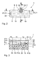
- the contact connection adapter 1 shown in the drawings is used to produce a temporary electrical contact between on the one hand a standardized IS-1 / IS-4 / DF-1 connector 2 of a shown in Fig. 1 shown heart electrode 3 and on the other hand, two conventional laboratory connectors 4, 5 - colloquially referred to as "banana plug" - which are to be connected via appropriate cables electrically connected to the connection sockets of a stimulation threshold analyzer, not shown.
- the adapter 1 has a substantially cuboid base body 6, which is injection-molded from a transparent, sterilizable plastic material in one piece.
- a sleeve-like receptacle 7 extending parallel to it is placed approximately in the center toward the top, which is accommodated with its cross-sectional area pointing towards the outside in a projection 8 which is triangular in profile. This extends over the top 9 of the adapter 1 away.
- the receptacle 7 is stepped from a muzzle-side plug-in area with the diameter d10 twice, namely on a slightly narrower plug-in area 11 with the diameter d11 and a lowest located plug-in area 12 with an even smaller diameter d12.
- the plug-in areas 10, 11 and 12 are adapted in their diameters d10, d11 and d12 to the corresponding outer diameter D13, D14, D15 of the plug shank 13, the ring contact 14 and located at the top of the plug 2 tip contact 15.
- the shaft 13 is separated from the ring contact 14 by a double circumferential ring seal 16.
- another pair of ring seals 17 is provided on the shank portion following the ring contact 14 prior to grading to the tip contact 15.
- the adapter For receiving the two laboratory plugs 4, 5, the adapter has a substantially cylindrical receptacle 18, 19 in two mutually perpendicular planes P18 and P19 in the insertion direction E one after the other. As can be seen from Fig. 1, these recordings 18, 19 correspond in depth about the length of the laboratory connector 4, 5 and terminate shortly before the mouth 20, 21 facing away from the narrow side 22 of the adapter 1. There they are permeable via an opening 23, 24 each for sterilization liquid.
- the cross sections of the receptacle 7 for the IS-1 / IS-4 / DF-1 plug 2 intersect on the one hand and the two receivers 18, 19 for the laboratory plugs 4, 5 on the other hand almost peripherally, such that the two cross-sectional volumes merge into one another via contact windows 25, 26 (FIG. 1). If now a laboratory plug 4, 5 are inserted into the receptacle 7 of the IS-1 plug 2 and into the receptacles 18, 19, the spring blades 27 of the laboratory plugs 4, 5 each provide an optimum electrical connection via the contact windows 25, 26 the ring contact 14 and tip contact 15 of the plug. 2
- the two receptacles 18, 19 have an offset V relative to each other for adaptation to the step-shaped reduction in diameter of the receptacle 7.
- the receptacle 7 is open for the plug 2 over its entire length laterally by a guide slot 8 in the lead-through slot 29. Furthermore, its innermost plug portion 12 continues into a feed-through hole 30 in the coaxial direction, which widens to a funnel-shaped mouth 31. About the feedthrough slot 29 and the feedthrough hole 30 of the current before the tip contact 15 portion of the stylet 28 is inserted into the receptacle 7 from the side. A direct threading is not possible because the stylet ends in a voluminous control handle. After insertion of the stylet in the receptacle 7, the plug 2 can then be inserted. To facilitate the stylet insertion of the feedthrough slot 29 is provided with 32 Ein slaughterstock.
Applications Claiming Priority (1)
| Application Number | Priority Date | Filing Date | Title |
|---|---|---|---|
| DE102005018806A DE102005018806A1 (de) | 2005-04-22 | 2005-04-22 | Kontaktverbindungs-Adapter zur Herstellung eines zeitweisen elektrischen Kontaktes zwischen zwei Steckern |
Publications (2)
| Publication Number | Publication Date |
|---|---|
| EP1714672A1 true EP1714672A1 (fr) | 2006-10-25 |
| EP1714672B1 EP1714672B1 (fr) | 2007-10-31 |
Family
ID=36779551
Family Applications (1)
| Application Number | Title | Priority Date | Filing Date |
|---|---|---|---|
| EP06006091A Active EP1714672B1 (fr) | 2005-04-22 | 2006-03-24 | Adaptateur de relation de contact visant la création d'un contact électrique occasionnel entre deux connecteurs |
Country Status (4)
| Country | Link |
|---|---|
| US (1) | US7217163B2 (fr) |
| EP (1) | EP1714672B1 (fr) |
| AT (1) | ATE376858T1 (fr) |
| DE (2) | DE102005018806A1 (fr) |
Cited By (1)
| Publication number | Priority date | Publication date | Assignee | Title |
|---|---|---|---|---|
| WO2012102745A3 (fr) * | 2011-01-27 | 2012-11-01 | Medtronic, Inc. | Adaptateur d'interface pour conducteurs électriques médicaux implantables |
Families Citing this family (7)
| Publication number | Priority date | Publication date | Assignee | Title |
|---|---|---|---|---|
| WO2008118430A1 (fr) * | 2007-03-26 | 2008-10-02 | Gkn Aerospace Services Structures Corp. | Connecteur utilisable avec des connexions à couches multiples et procédé d'utilisation de celui-ci |
| US7677929B2 (en) * | 2008-06-04 | 2010-03-16 | Daphne Bradford-Stagg | Sacrificial laptop computer power connector |
| US7854633B2 (en) * | 2008-09-05 | 2010-12-21 | Apple Inc. | Low profile plug receptacle |
| US8353729B2 (en) * | 2010-02-18 | 2013-01-15 | Apple Inc. | Low profile connector system |
| JP2014219436A (ja) * | 2013-04-30 | 2014-11-20 | 株式会社リコー | 読み出し装置及び同装置を供える画像形成装置 |
| RU193619U1 (ru) * | 2017-09-11 | 2019-11-07 | Александр Николаевич Александров | Переходник к постоянному кардиостимулятору для временной электрокардиостимуляции |
| WO2019050438A1 (fr) * | 2017-09-11 | 2019-03-14 | Александр Николаевич АЛЕКСАНДРОВ | Adaptateur de stimulateur cardiaque désimplanté pour électrostimulation cardiaque temporaire |
Citations (4)
| Publication number | Priority date | Publication date | Assignee | Title |
|---|---|---|---|---|
| US5782892A (en) * | 1997-04-25 | 1998-07-21 | Medtronic, Inc. | Medical lead adaptor for external medical device |
| DE19810262A1 (de) | 1998-03-10 | 1999-09-16 | Bisping Hans Juergen | Testkabelanordnung |
| US6343233B1 (en) * | 1997-04-25 | 2002-01-29 | Medtronic, Inc. | Medical lead adaptor |
| US20030120327A1 (en) * | 2001-12-20 | 2003-06-26 | Mark Tobritzhofer | Medical lead adaptor assembly with retainer |
Family Cites Families (7)
| Publication number | Priority date | Publication date | Assignee | Title |
|---|---|---|---|---|
| US4860750A (en) * | 1986-04-17 | 1989-08-29 | Intermedics Inc. | Sidelock pacer lead connector |
| DE8808698U1 (fr) * | 1988-07-04 | 1988-09-22 | Biotronik Mess- Und Therapiegeraete Gmbh & Co Ingenieurbuero Berlin, 1000 Berlin, De | |
| US5413595A (en) * | 1993-10-15 | 1995-05-09 | Pacesetter, Inc. | Lead retention and seal for implantable medical device |
| EP0826390A3 (fr) * | 1996-08-06 | 1998-03-25 | Sulzer Osypka GmbH | Elément de connexion pour l'embout externe d'une électrode chirurgicale |
| DE19938960A1 (de) * | 1998-03-10 | 2001-02-22 | Bisping Hans Juergen | Testkabelanordnung |
| US6044302A (en) * | 1999-01-07 | 2000-03-28 | Cardiac Pacemakers, Inc. | Apparatus for connecting a left ventricular access lead to a cardiac rhythm management device |
| US7047077B2 (en) * | 2002-08-16 | 2006-05-16 | Cardiac Pacemakers, Inc. | Connector port construction technique for implantable medical device |
-
2005
- 2005-04-22 DE DE102005018806A patent/DE102005018806A1/de not_active Withdrawn
-
2006
- 2006-03-24 AT AT06006091T patent/ATE376858T1/de not_active IP Right Cessation
- 2006-03-24 DE DE502006000157T patent/DE502006000157D1/de active Active
- 2006-03-24 EP EP06006091A patent/EP1714672B1/fr active Active
- 2006-04-24 US US11/409,266 patent/US7217163B2/en not_active Expired - Fee Related
Patent Citations (5)
| Publication number | Priority date | Publication date | Assignee | Title |
|---|---|---|---|---|
| US5782892A (en) * | 1997-04-25 | 1998-07-21 | Medtronic, Inc. | Medical lead adaptor for external medical device |
| US6343233B1 (en) * | 1997-04-25 | 2002-01-29 | Medtronic, Inc. | Medical lead adaptor |
| DE19810262A1 (de) | 1998-03-10 | 1999-09-16 | Bisping Hans Juergen | Testkabelanordnung |
| US6708067B1 (en) | 1998-03-10 | 2004-03-16 | Hans Jurgen Bisping | Test cable arrangement |
| US20030120327A1 (en) * | 2001-12-20 | 2003-06-26 | Mark Tobritzhofer | Medical lead adaptor assembly with retainer |
Non-Patent Citations (1)
| Title |
|---|
| ANONYMOUS: "Cable connector for electrical measurements", RESEARCH DISCLOSURE, MASON PUBLICATIONS, HAMPSHIRE, GB, vol. 395, no. 11, March 1997 (1997-03-01), XP007121588, ISSN: 0374-4353 * |
Cited By (1)
| Publication number | Priority date | Publication date | Assignee | Title |
|---|---|---|---|---|
| WO2012102745A3 (fr) * | 2011-01-27 | 2012-11-01 | Medtronic, Inc. | Adaptateur d'interface pour conducteurs électriques médicaux implantables |
Also Published As
| Publication number | Publication date |
|---|---|
| DE102005018806A1 (de) | 2006-10-26 |
| ATE376858T1 (de) | 2007-11-15 |
| US20060240714A1 (en) | 2006-10-26 |
| EP1714672B1 (fr) | 2007-10-31 |
| US7217163B2 (en) | 2007-05-15 |
| DE502006000157D1 (de) | 2007-12-13 |
Similar Documents
| Publication | Publication Date | Title |
|---|---|---|
| EP1714672B1 (fr) | Adaptateur de relation de contact visant la création d'un contact électrique occasionnel entre deux connecteurs | |
| DE60113472T2 (de) | Elektrischer Steckverbinder für eine mehrpolige medizinische Elektrode | |
| DE2853809C2 (fr) | ||
| DE4402058C1 (de) | Implantierbares, passageres Elektrodenkabel | |
| EP1253964B1 (fr) | Adaptateur de contrainte pour catheter | |
| DE2309204C2 (de) | Steckvorrichtung für den Anschluß einer Anzahl von Zuleitungen für Herzelektroden an einen Herzschrittmacher | |
| DE4116520A1 (de) | Implantierbarer leitfaehiger verbinder | |
| DE19938960A1 (de) | Testkabelanordnung | |
| DE102007026645A1 (de) | Elektrodenanordnung und Messvorrichtung zur Messung der elektrischen Aktivität in einem elektrisch aktiven Gewebe | |
| EP1061995B1 (fr) | Configuration de cable d'essai | |
| DE102011013170B4 (de) | Temporärer berührungssicherer Verbinder für Herzdrähte | |
| DE102013001021B4 (de) | Externer Herzschrittmacher mit einer über einen Steckverbinder angeschlossenen, temporär mit einem Herzen verbindbaren Elektrode | |
| DE102012009058B4 (de) | Bipolarer Elektrodenanschluss | |
| WO2017140727A1 (fr) | Prise multiple pour appareil chirurgical, générateur haute fréquence électrochirurgical, fiche pour appareil électrochirurgical et système électrochirurgical | |
| EP3630266B1 (fr) | Adaptateur électro-médical, électrode électro-médicale et émetteur d'impulsions électro-médical | |
| EP0823263A1 (fr) | Elément de connexion pour l'embout externe d'une électrode chirurgicale | |
| DE19959655B4 (de) | Chirurgische Elektrode | |
| DE102008007542A1 (de) | Multipolare Elektrodenleitung | |
| DE69725341T2 (de) | Kontaktelemente einer vielpoligen steckverbindung an einem elektrodenkabel für eine implantierbare medizinische vorrichtung | |
| DE102011109880B4 (de) | Verlängerungskabel für temporäre Herzschrittmacher Elektroden | |
| WO2022189612A1 (fr) | Connecteur pour une électrode électromédicale, connecteur homologue, générateur d'impulsions électromédicales, électrode électromédicale et connexion par fiche électromédicale | |
| DE102020117142A1 (de) | Medizinisches Handhabungsset | |
| DE202012003220U1 (de) | Nadelelektrode mit Griffteil mit flächig ausgeformter Oberfläche | |
| DE102016125223A1 (de) | Vorrichtung zur Stromversorgung von Implantaten | |
| EP3181189A1 (fr) | Conducteur d'électrode implantable et jeu de modules de conducteurs d'électrode |
Legal Events
| Date | Code | Title | Description |
|---|---|---|---|
| PUAI | Public reference made under article 153(3) epc to a published international application that has entered the european phase |
Free format text: ORIGINAL CODE: 0009012 |
|
| AK | Designated contracting states |
Kind code of ref document: A1 Designated state(s): AT BE BG CH CY CZ DE DK EE ES FI FR GB GR HU IE IS IT LI LT LU LV MC NL PL PT RO SE SI SK TR |
|
| AX | Request for extension of the european patent |
Extension state: AL BA HR MK YU |
|
| 17P | Request for examination filed |
Effective date: 20061027 |
|
| GRAP | Despatch of communication of intention to grant a patent |
Free format text: ORIGINAL CODE: EPIDOSNIGR1 |
|
| GRAC | Information related to communication of intention to grant a patent modified |
Free format text: ORIGINAL CODE: EPIDOSCIGR1 |
|
| AKX | Designation fees paid |
Designated state(s): AT BE BG CH CY CZ DE DK EE ES FI FR GB GR HU IE IS IT LI LT LU LV MC NL PL PT RO SE SI SK TR |
|
| GRAS | Grant fee paid |
Free format text: ORIGINAL CODE: EPIDOSNIGR3 |
|
| GRAA | (expected) grant |
Free format text: ORIGINAL CODE: 0009210 |
|
| AK | Designated contracting states |
Kind code of ref document: B1 Designated state(s): AT BE BG CH CY CZ DE DK EE ES FI FR GB GR HU IE IS IT LI LT LU LV MC NL PL PT RO SE SI SK TR |
|
| REG | Reference to a national code |
Ref country code: GB Ref legal event code: FG4D Free format text: NOT ENGLISH |
|
| REG | Reference to a national code |
Ref country code: SE Ref legal event code: TRGR |
|
| REG | Reference to a national code |
Ref country code: IE Ref legal event code: FG4D Free format text: LANGUAGE OF EP DOCUMENT: GERMAN |
|
| REG | Reference to a national code |
Ref country code: CH Ref legal event code: EP |
|
| REF | Corresponds to: |
Ref document number: 502006000157 Country of ref document: DE Date of ref document: 20071213 Kind code of ref document: P |
|
| GBT | Gb: translation of ep patent filed (gb section 77(6)(a)/1977) |
Effective date: 20071127 |
|
| ET | Fr: translation filed | ||
| PG25 | Lapsed in a contracting state [announced via postgrant information from national office to epo] |
Ref country code: ES Free format text: LAPSE BECAUSE OF FAILURE TO SUBMIT A TRANSLATION OF THE DESCRIPTION OR TO PAY THE FEE WITHIN THE PRESCRIBED TIME-LIMIT Effective date: 20080211 |
|
| PG25 | Lapsed in a contracting state [announced via postgrant information from national office to epo] |
Ref country code: SI Free format text: LAPSE BECAUSE OF FAILURE TO SUBMIT A TRANSLATION OF THE DESCRIPTION OR TO PAY THE FEE WITHIN THE PRESCRIBED TIME-LIMIT Effective date: 20071031 Ref country code: PT Free format text: LAPSE BECAUSE OF FAILURE TO SUBMIT A TRANSLATION OF THE DESCRIPTION OR TO PAY THE FEE WITHIN THE PRESCRIBED TIME-LIMIT Effective date: 20080331 Ref country code: PL Free format text: LAPSE BECAUSE OF FAILURE TO SUBMIT A TRANSLATION OF THE DESCRIPTION OR TO PAY THE FEE WITHIN THE PRESCRIBED TIME-LIMIT Effective date: 20071031 Ref country code: LV Free format text: LAPSE BECAUSE OF FAILURE TO SUBMIT A TRANSLATION OF THE DESCRIPTION OR TO PAY THE FEE WITHIN THE PRESCRIBED TIME-LIMIT Effective date: 20071031 Ref country code: LT Free format text: LAPSE BECAUSE OF FAILURE TO SUBMIT A TRANSLATION OF THE DESCRIPTION OR TO PAY THE FEE WITHIN THE PRESCRIBED TIME-LIMIT Effective date: 20071031 Ref country code: IS Free format text: LAPSE BECAUSE OF FAILURE TO SUBMIT A TRANSLATION OF THE DESCRIPTION OR TO PAY THE FEE WITHIN THE PRESCRIBED TIME-LIMIT Effective date: 20080229 Ref country code: BG Free format text: LAPSE BECAUSE OF FAILURE TO SUBMIT A TRANSLATION OF THE DESCRIPTION OR TO PAY THE FEE WITHIN THE PRESCRIBED TIME-LIMIT Effective date: 20080131 |
|
| REG | Reference to a national code |
Ref country code: IE Ref legal event code: FD4D |
|
| PG25 | Lapsed in a contracting state [announced via postgrant information from national office to epo] |
Ref country code: DK Free format text: LAPSE BECAUSE OF FAILURE TO SUBMIT A TRANSLATION OF THE DESCRIPTION OR TO PAY THE FEE WITHIN THE PRESCRIBED TIME-LIMIT Effective date: 20071031 Ref country code: CZ Free format text: LAPSE BECAUSE OF FAILURE TO SUBMIT A TRANSLATION OF THE DESCRIPTION OR TO PAY THE FEE WITHIN THE PRESCRIBED TIME-LIMIT Effective date: 20071031 |
|
| PG25 | Lapsed in a contracting state [announced via postgrant information from national office to epo] |
Ref country code: RO Free format text: LAPSE BECAUSE OF FAILURE TO SUBMIT A TRANSLATION OF THE DESCRIPTION OR TO PAY THE FEE WITHIN THE PRESCRIBED TIME-LIMIT Effective date: 20071031 Ref country code: SK Free format text: LAPSE BECAUSE OF FAILURE TO SUBMIT A TRANSLATION OF THE DESCRIPTION OR TO PAY THE FEE WITHIN THE PRESCRIBED TIME-LIMIT Effective date: 20071031 |
|
| PLBE | No opposition filed within time limit |
Free format text: ORIGINAL CODE: 0009261 |
|
| STAA | Information on the status of an ep patent application or granted ep patent |
Free format text: STATUS: NO OPPOSITION FILED WITHIN TIME LIMIT |
|
| BERE | Be: lapsed |
Owner name: BIOTRONIK CRM PATENT A.G. Effective date: 20080331 |
|
| 26N | No opposition filed |
Effective date: 20080801 |
|
| PG25 | Lapsed in a contracting state [announced via postgrant information from national office to epo] |
Ref country code: MC Free format text: LAPSE BECAUSE OF NON-PAYMENT OF DUE FEES Effective date: 20080331 Ref country code: IE Free format text: LAPSE BECAUSE OF FAILURE TO SUBMIT A TRANSLATION OF THE DESCRIPTION OR TO PAY THE FEE WITHIN THE PRESCRIBED TIME-LIMIT Effective date: 20071031 |
|
| PG25 | Lapsed in a contracting state [announced via postgrant information from national office to epo] |
Ref country code: EE Free format text: LAPSE BECAUSE OF FAILURE TO SUBMIT A TRANSLATION OF THE DESCRIPTION OR TO PAY THE FEE WITHIN THE PRESCRIBED TIME-LIMIT Effective date: 20071031 Ref country code: GR Free format text: LAPSE BECAUSE OF FAILURE TO SUBMIT A TRANSLATION OF THE DESCRIPTION OR TO PAY THE FEE WITHIN THE PRESCRIBED TIME-LIMIT Effective date: 20080201 |
|
| PG25 | Lapsed in a contracting state [announced via postgrant information from national office to epo] |
Ref country code: FI Free format text: LAPSE BECAUSE OF FAILURE TO SUBMIT A TRANSLATION OF THE DESCRIPTION OR TO PAY THE FEE WITHIN THE PRESCRIBED TIME-LIMIT Effective date: 20071031 Ref country code: BE Free format text: LAPSE BECAUSE OF NON-PAYMENT OF DUE FEES Effective date: 20080331 |
|
| PGFP | Annual fee paid to national office [announced via postgrant information from national office to epo] |
Ref country code: NL Payment date: 20090324 Year of fee payment: 4 |
|
| PG25 | Lapsed in a contracting state [announced via postgrant information from national office to epo] |
Ref country code: CY Free format text: LAPSE BECAUSE OF FAILURE TO SUBMIT A TRANSLATION OF THE DESCRIPTION OR TO PAY THE FEE WITHIN THE PRESCRIBED TIME-LIMIT Effective date: 20071031 |
|
| PG25 | Lapsed in a contracting state [announced via postgrant information from national office to epo] |
Ref country code: AT Free format text: LAPSE BECAUSE OF NON-PAYMENT OF DUE FEES Effective date: 20080324 |
|
| PG25 | Lapsed in a contracting state [announced via postgrant information from national office to epo] |
Ref country code: HU Free format text: LAPSE BECAUSE OF FAILURE TO SUBMIT A TRANSLATION OF THE DESCRIPTION OR TO PAY THE FEE WITHIN THE PRESCRIBED TIME-LIMIT Effective date: 20080501 Ref country code: LU Free format text: LAPSE BECAUSE OF NON-PAYMENT OF DUE FEES Effective date: 20080324 |
|
| PG25 | Lapsed in a contracting state [announced via postgrant information from national office to epo] |
Ref country code: TR Free format text: LAPSE BECAUSE OF FAILURE TO SUBMIT A TRANSLATION OF THE DESCRIPTION OR TO PAY THE FEE WITHIN THE PRESCRIBED TIME-LIMIT Effective date: 20071031 |
|
| REG | Reference to a national code |
Ref country code: NL Ref legal event code: V1 Effective date: 20101001 |
|
| PG25 | Lapsed in a contracting state [announced via postgrant information from national office to epo] |
Ref country code: NL Free format text: LAPSE BECAUSE OF NON-PAYMENT OF DUE FEES Effective date: 20101001 |
|
| PGFP | Annual fee paid to national office [announced via postgrant information from national office to epo] |
Ref country code: IT Payment date: 20090331 Year of fee payment: 4 |
|
| PGFP | Annual fee paid to national office [announced via postgrant information from national office to epo] |
Ref country code: SE Payment date: 20120322 Year of fee payment: 7 Ref country code: GB Payment date: 20120322 Year of fee payment: 7 |
|
| REG | Reference to a national code |
Ref country code: SE Ref legal event code: EUG |
|
| PG25 | Lapsed in a contracting state [announced via postgrant information from national office to epo] |
Ref country code: SE Free format text: LAPSE BECAUSE OF NON-PAYMENT OF DUE FEES Effective date: 20130325 |
|
| GBPC | Gb: european patent ceased through non-payment of renewal fee |
Effective date: 20130324 |
|
| PG25 | Lapsed in a contracting state [announced via postgrant information from national office to epo] |
Ref country code: GB Free format text: LAPSE BECAUSE OF NON-PAYMENT OF DUE FEES Effective date: 20130324 |
|
| REG | Reference to a national code |
Ref country code: FR Ref legal event code: PLFP Year of fee payment: 10 |
|
| PGFP | Annual fee paid to national office [announced via postgrant information from national office to epo] |
Ref country code: FR Payment date: 20150319 Year of fee payment: 10 |
|
| REG | Reference to a national code |
Ref country code: DE Ref legal event code: R082 Ref document number: 502006000157 Country of ref document: DE Representative=s name: RANDOLL, SOEREN, DIPL.-CHEM. UNIV. DR. RER. NA, DE |
|
| REG | Reference to a national code |
Ref country code: FR Ref legal event code: ST Effective date: 20161130 |
|
| PG25 | Lapsed in a contracting state [announced via postgrant information from national office to epo] |
Ref country code: FR Free format text: LAPSE BECAUSE OF NON-PAYMENT OF DUE FEES Effective date: 20160331 |
|
| REG | Reference to a national code |
Ref country code: DE Ref legal event code: R082 Ref document number: 502006000157 Country of ref document: DE Ref country code: DE Ref legal event code: R081 Ref document number: 502006000157 Country of ref document: DE Owner name: BIOTRONIK SE & CO. KG, DE Free format text: FORMER OWNER: BIOTRONIK CRM PATENT AG, BAAR, CH |
|
| PGFP | Annual fee paid to national office [announced via postgrant information from national office to epo] |
Ref country code: CH Payment date: 20180326 Year of fee payment: 13 |
|
| PGFP | Annual fee paid to national office [announced via postgrant information from national office to epo] |
Ref country code: DE Payment date: 20180328 Year of fee payment: 13 |
|
| REG | Reference to a national code |
Ref country code: DE Ref legal event code: R119 Ref document number: 502006000157 Country of ref document: DE |
|
| REG | Reference to a national code |
Ref country code: CH Ref legal event code: PL |
|
| PG25 | Lapsed in a contracting state [announced via postgrant information from national office to epo] |
Ref country code: CH Free format text: LAPSE BECAUSE OF NON-PAYMENT OF DUE FEES Effective date: 20190331 Ref country code: LI Free format text: LAPSE BECAUSE OF NON-PAYMENT OF DUE FEES Effective date: 20190331 Ref country code: DE Free format text: LAPSE BECAUSE OF NON-PAYMENT OF DUE FEES Effective date: 20191001 |