EP1712697A2 - Profilé de montage - Google Patents
Profilé de montage Download PDFInfo
- Publication number
- EP1712697A2 EP1712697A2 EP06405164A EP06405164A EP1712697A2 EP 1712697 A2 EP1712697 A2 EP 1712697A2 EP 06405164 A EP06405164 A EP 06405164A EP 06405164 A EP06405164 A EP 06405164A EP 1712697 A2 EP1712697 A2 EP 1712697A2
- Authority
- EP
- European Patent Office
- Prior art keywords
- mounting profile
- mounting
- elements
- device parts
- profile
- Prior art date
- Legal status (The legal status is an assumption and is not a legal conclusion. Google has not performed a legal analysis and makes no representation as to the accuracy of the status listed.)
- Withdrawn
Links
Images


Classifications
-
- B—PERFORMING OPERATIONS; TRANSPORTING
- B21—MECHANICAL METAL-WORKING WITHOUT ESSENTIALLY REMOVING MATERIAL; PUNCHING METAL
- B21D—WORKING OR PROCESSING OF SHEET METAL OR METAL TUBES, RODS OR PROFILES WITHOUT ESSENTIALLY REMOVING MATERIAL; PUNCHING METAL
- B21D47/00—Making rigid structural elements or units, e.g. honeycomb structures
- B21D47/04—Making rigid structural elements or units, e.g. honeycomb structures composite sheet metal profiles
-
- E—FIXED CONSTRUCTIONS
- E04—BUILDING
- E04C—STRUCTURAL ELEMENTS; BUILDING MATERIALS
- E04C3/00—Structural elongated elements designed for load-supporting
- E04C3/02—Joists; Girders, trusses, or trusslike structures, e.g. prefabricated; Lintels; Transoms; Braces
- E04C3/04—Joists; Girders, trusses, or trusslike structures, e.g. prefabricated; Lintels; Transoms; Braces of metal
- E04C3/06—Joists; Girders, trusses, or trusslike structures, e.g. prefabricated; Lintels; Transoms; Braces of metal with substantially solid, i.e. unapertured, web
- E04C3/07—Joists; Girders, trusses, or trusslike structures, e.g. prefabricated; Lintels; Transoms; Braces of metal with substantially solid, i.e. unapertured, web at least partly of bent or otherwise deformed strip- or sheet-like material
-
- E—FIXED CONSTRUCTIONS
- E04—BUILDING
- E04C—STRUCTURAL ELEMENTS; BUILDING MATERIALS
- E04C3/00—Structural elongated elements designed for load-supporting
- E04C3/02—Joists; Girders, trusses, or trusslike structures, e.g. prefabricated; Lintels; Transoms; Braces
- E04C3/04—Joists; Girders, trusses, or trusslike structures, e.g. prefabricated; Lintels; Transoms; Braces of metal
- E04C3/08—Joists; Girders, trusses, or trusslike structures, e.g. prefabricated; Lintels; Transoms; Braces of metal with apertured web, e.g. with a web consisting of bar-like components; Honeycomb girders
- E04C3/09—Joists; Girders, trusses, or trusslike structures, e.g. prefabricated; Lintels; Transoms; Braces of metal with apertured web, e.g. with a web consisting of bar-like components; Honeycomb girders at least partly of bent or otherwise deformed strip- or sheet-like material
-
- H—ELECTRICITY
- H02—GENERATION; CONVERSION OR DISTRIBUTION OF ELECTRIC POWER
- H02G—INSTALLATION OF ELECTRIC CABLES OR LINES, OR OF COMBINED OPTICAL AND ELECTRIC CABLES OR LINES
- H02G3/00—Installations of electric cables or lines or protective tubing therefor in or on buildings, equivalent structures or vehicles
- H02G3/02—Details
- H02G3/04—Protective tubing or conduits, e.g. cable ladders or cable troughs
- H02G3/0437—Channels
- H02G3/045—Channels provided with perforations or slots permitting introduction or exit of wires
-
- H—ELECTRICITY
- H02—GENERATION; CONVERSION OR DISTRIBUTION OF ELECTRIC POWER
- H02G—INSTALLATION OF ELECTRIC CABLES OR LINES, OR OF COMBINED OPTICAL AND ELECTRIC CABLES OR LINES
- H02G3/00—Installations of electric cables or lines or protective tubing therefor in or on buildings, equivalent structures or vehicles
- H02G3/02—Details
- H02G3/04—Protective tubing or conduits, e.g. cable ladders or cable troughs
- H02G3/0456—Ladders or other supports
-
- E—FIXED CONSTRUCTIONS
- E04—BUILDING
- E04C—STRUCTURAL ELEMENTS; BUILDING MATERIALS
- E04C3/00—Structural elongated elements designed for load-supporting
- E04C3/02—Joists; Girders, trusses, or trusslike structures, e.g. prefabricated; Lintels; Transoms; Braces
- E04C3/04—Joists; Girders, trusses, or trusslike structures, e.g. prefabricated; Lintels; Transoms; Braces of metal
- E04C2003/0404—Joists; Girders, trusses, or trusslike structures, e.g. prefabricated; Lintels; Transoms; Braces of metal beams, girders, or joists characterised by cross-sectional aspects
- E04C2003/0408—Joists; Girders, trusses, or trusslike structures, e.g. prefabricated; Lintels; Transoms; Braces of metal beams, girders, or joists characterised by cross-sectional aspects characterised by assembly or the cross-section
- E04C2003/0413—Joists; Girders, trusses, or trusslike structures, e.g. prefabricated; Lintels; Transoms; Braces of metal beams, girders, or joists characterised by cross-sectional aspects characterised by assembly or the cross-section being built up from several parts
-
- E—FIXED CONSTRUCTIONS
- E04—BUILDING
- E04C—STRUCTURAL ELEMENTS; BUILDING MATERIALS
- E04C3/00—Structural elongated elements designed for load-supporting
- E04C3/02—Joists; Girders, trusses, or trusslike structures, e.g. prefabricated; Lintels; Transoms; Braces
- E04C3/04—Joists; Girders, trusses, or trusslike structures, e.g. prefabricated; Lintels; Transoms; Braces of metal
- E04C2003/0404—Joists; Girders, trusses, or trusslike structures, e.g. prefabricated; Lintels; Transoms; Braces of metal beams, girders, or joists characterised by cross-sectional aspects
- E04C2003/0426—Joists; Girders, trusses, or trusslike structures, e.g. prefabricated; Lintels; Transoms; Braces of metal beams, girders, or joists characterised by cross-sectional aspects characterised by material distribution in cross section
- E04C2003/043—Joists; Girders, trusses, or trusslike structures, e.g. prefabricated; Lintels; Transoms; Braces of metal beams, girders, or joists characterised by cross-sectional aspects characterised by material distribution in cross section the hollow cross-section comprising at least one enclosed cavity
-
- E—FIXED CONSTRUCTIONS
- E04—BUILDING
- E04C—STRUCTURAL ELEMENTS; BUILDING MATERIALS
- E04C3/00—Structural elongated elements designed for load-supporting
- E04C3/02—Joists; Girders, trusses, or trusslike structures, e.g. prefabricated; Lintels; Transoms; Braces
- E04C3/04—Joists; Girders, trusses, or trusslike structures, e.g. prefabricated; Lintels; Transoms; Braces of metal
- E04C2003/0404—Joists; Girders, trusses, or trusslike structures, e.g. prefabricated; Lintels; Transoms; Braces of metal beams, girders, or joists characterised by cross-sectional aspects
- E04C2003/0443—Joists; Girders, trusses, or trusslike structures, e.g. prefabricated; Lintels; Transoms; Braces of metal beams, girders, or joists characterised by cross-sectional aspects characterised by substantial shape of the cross-section
- E04C2003/0465—Joists; Girders, trusses, or trusslike structures, e.g. prefabricated; Lintels; Transoms; Braces of metal beams, girders, or joists characterised by cross-sectional aspects characterised by substantial shape of the cross-section square- or rectangular-shaped
-
- E—FIXED CONSTRUCTIONS
- E04—BUILDING
- E04C—STRUCTURAL ELEMENTS; BUILDING MATERIALS
- E04C3/00—Structural elongated elements designed for load-supporting
- E04C3/02—Joists; Girders, trusses, or trusslike structures, e.g. prefabricated; Lintels; Transoms; Braces
- E04C3/04—Joists; Girders, trusses, or trusslike structures, e.g. prefabricated; Lintels; Transoms; Braces of metal
- E04C2003/0404—Joists; Girders, trusses, or trusslike structures, e.g. prefabricated; Lintels; Transoms; Braces of metal beams, girders, or joists characterised by cross-sectional aspects
- E04C2003/0443—Joists; Girders, trusses, or trusslike structures, e.g. prefabricated; Lintels; Transoms; Braces of metal beams, girders, or joists characterised by cross-sectional aspects characterised by substantial shape of the cross-section
- E04C2003/0469—Joists; Girders, trusses, or trusslike structures, e.g. prefabricated; Lintels; Transoms; Braces of metal beams, girders, or joists characterised by cross-sectional aspects characterised by substantial shape of the cross-section triangular-shaped
Definitions
- the invention relates to a mounting profile according to the preamble of patent claim 1.
- the present invention is therefore based on the object to provide an improved mounting profile.
- a lighter and versatile usable mounting profile is created.
- the mounting profile which in particular serves to carry loads and / or the guidance of cables, consists of a first and a second rod-shaped device part, which are positively connected to each other in such a way that a load-bearing hollow profile with rectangular, triangular or trapezoidal Cross-section is formed, and have the peripheral mutually corresponding first side elements, which are interconnected via a provided on the first and / or second device part second side member.
- the two device parts or the first and / or second side elements of the two device parts are configured identically, but optionally provided with different openings.
- the two parts of the device are preferably cut from a piece of sheet metal, wherein the first side elements of the two parts of the device within the sheet metal piece interlocking with each other along a peripheral line.
- the two parts of the device can therefore be manufactured without loss of material in one operation.
- the mounting profile which can be made with a few simple steps by assembling and connecting the two parts of the device, is attached to save material, has a low weight, is easily accessible on the inside and universally applicable. By choosing identical parts of the device, the production and assembly can be further simplified.
- At least one of the side elements is provided with structural elements of increased strength, for example with a series of openings which are each bounded by a projecting into the mounting profile collar. Due to the manufactured collar receives the relevant side element and thus the mounting profile increased strength. Cables and cables can also be fed in and out through the openings. Furthermore, cantilevers and connecting elements can also be used in the openings. The openings may be stamped with the opening edges being stopped to form the desired collar.
- the first connecting elements may be cut-out and curved tabs or end pieces held on one or both sides, which can be introduced into the second connecting elements configured as openings and optionally locked by bending or pressing or by means of a locking element.
- End pieces serving as first connecting elements, which can be introduced into an opening on the opposite device part can be realized particularly advantageously on the first side element, since only a corresponding adaptation of the profile of the section is necessary, by means of which the two device parts are separated from one another.
- the two parts of the device can also be connected to each other particularly easily, since the end pieces point in the direction in which the device parts are guided against each other, and thus automatically engage in the second connecting elements.
- the first and / or second side elements can furthermore have an optionally divided flange element which, at an angle, overlaps the adjoining side element and is optionally provided with the first or second connecting elements.
- the first side elements of the two device parts are preferably provided with a series of toothed elements, such as triangles, that they interlock without interruption and thus can be cut or punched in a simple manner, only by a correspondingly extending section of a piece of sheet metal.
- At least one block or tubular rigid or hard-elastic stabilization, end, coupling or connection module made of metal, wood or plastic provided that connects at least partially positively to the mounting profile and by the aesthetic or functional completion of the mounting profile, a coupling to other mounting profiles or mounting elements, or a Bundling of several mounting profiles is made possible through which an individual adaptation to different loads is possible.
- To bundle mounting profiles are preferably elements, such as appropriately designed openings and collar, or hooks, etc., provided that allow the positive coupling of several mounting profiles or at least support.
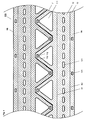
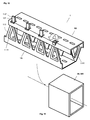
- Figure 1 shows two punched out of a sheet 100 identical device parts 1A, 1B, which are provided for producing a mounting profile 1.
- a first and a second bending line B1 or B2 are shown, by which the device parts 1A, 1B are divided into three areas 11, 12 and 13.
- the first bending line B1 separates a first and a second side element 11, 12 provided with mounting openings 121 from one another.
- a strip-like flange 13 is separated from the second side member 12.
- Second connecting elements or openings 131 are provided on the flange element 13 of the first device part 1A, which correspond to first connecting elements 112 provided on the first side element 11 of the second device part 1B.
- the first side elements 11 of the two device parts 1A, 1B are provided with interlocking triangles 110, from which openings 111 are cut out.
- the precise mutual sawtooth cutting allows the use of a narrow sheet metal strip 100 and thus the reduction of material costs and weight and the avoidance of material losses.
- Figure 13 As shown in Figure 13, of course, other more or less intermeshing or peripherally adjoining, for example, rectangular or trapezoidal shapes are selected.
- the two device parts 1A, 1B can be stamped with said elements with minimal effort in a single step from the sheet 100, the thickness of which is selected according to the strength required for the mounting profile to be produced. Typically, a galvanized sheet is selected with a thickness of a few millimeters.
- FIG. 2 shows the two device parts 1A, 1B of FIG. 1, which are still interlocked but separated by a few millimeters.
- FIG. 3 shows one of the device parts 1A, 1B in a spatial view with the first bending line B1 about which the two side elements 11, 12 are bent against each other, and with the second bending line B2 around which the flange element 13 is angled against the first side element 12.
- FIG. 4 shows the two finished bent device parts 1A, 1B of FIG. 1 during mutual assembly.
- the two side elements 11, 12 of the device parts 1A, 1B form an L-profile and are complemented by the angled flange 13 to a lobe to a U-profile.
- the first side element 11 of the one device part 1A is connected to the second side element 12 of the other device part 1B such that a hollow rectangular profile is formed, as shown in FIG.
- first side elements 11 and the second side elements 12 each lie in mutually parallel planes.
- the flange members 13 overlap the first side members 11 such that the first and second connecting elements 112, 131 can cooperate.
- the first connection elements 112 provided on the first side elements 11 are tabs or hooks which are cut out of the sheet metal 100 and bent, for example, which can enter into the second connection elements 131 designed as openings and can be anchored there.
- the tabs or hooks introduced into the openings are crimped or locked by means of a locking element 114 (see the embodiment of FIG. 7, for example).
- a stable mounting profile 1 is formed by the two interconnected device parts 1A, 1B, the strength of which can be increased by further measures.
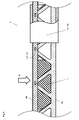
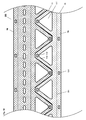
- FIG. 6 shows a section through an inventive mounting profile 1, whose first side elements 111 are provided with openings 111 to which a collar 1111 projecting into the mounting profile 1 adjoins.
- the material of the openings 111 was therefore not cut out, at least not completely, but pressed inwards (or outside) (see, for example, also Figure 9) to reinforce the mounting profile 1.
- the collar 1111 which ensures increased strength even at a depth of a few millimeters, compensates for the cut-out material by a multiple and gives the mounting profile 1 a greatly increased torsional and buckling strength.
- the formation of the collar 1111 can be carried out efficiently in the same operation with the cutting of the two device parts 1A, 1B.
- the first connecting element 112 is clearly visible, which engages as a lug in the second connecting element 131 designed as an opening and can be locked by means of a wedge 114.
- the tab 112 can also be bent or crimped to the side, so that it can not retreat through the opening 131.
- cables and lines can advantageously be laid within the mounting profile 1.
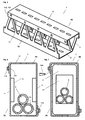
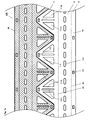
- FIG. 7 shows the mounting profile 1 of FIG. 6 with a stabilization module 2 inserted therein, which has an opening 21 serving to pass through cables or lines 5.
- Stabilization modules 2 are preferably used at locations where external forces act on the mounting profile. Particularly advantageous is the use of hard elastic stabilization modules 2, by which the punctiform acting forces are distributed flat on the mounting profile 1.
- FIG. 8 shows the mounting profile 1 of FIG. 5 under the action of a load F L at a point which is reinforced by means of an inner stabilization module 2.
- FIG. 8 also shows a sleeve-shaped outer stabilization module 20, 200 which comprises and stabilizes the mounting profile 1 in a form-fitting manner.
- the outer stabilization module 20, 200 can also serve as an end module, which completes the mounting profile 1 aesthetically and / or functionally advantageous.
- FIG. 9 shows two identical device parts 1A, 1B punched out of a metal sheet 100, on which simpler first connecting elements 112 'are provided.
- the first connection elements 112 ' consist of plate-shaped end pieces, which are attached to the triangles 110 of the first side elements 111.
- FIG. 11 shows an outer stabilization or end module 20, 200 serving to receive the mounting profile 1 of FIG.
- FIG. 12 shows two non-identical device parts 1A, 1B which are punched out of a sheet metal 100 and are provided for producing a mounting profile 1 which has a hollow profile with a triangular cross-section.
- the second side member 12 is completely missing.
- FIG. 13 shows a device part 1A, 1B with rectangular tooth elements 110 with rectangular, projecting openings 111.
- FIG. 14 schematically shows three mounting profiles 1 produced by means of the device parts 1A, 1B of FIG. 12, which are connected to one another in a form-fitting manner by means of openings 111 and collar 1111 and by means of a connecting element 2000.
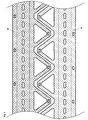
- FIG. 15 shows the device parts 1A, 1B of FIG. 1 with preferably configured triangular toothed elements 110, which have two approximately triangular perforations or openings 111A, 111B arranged symmetrically to one another, in the axis of symmetry of which a web 1110 is arranged, which considerably increases the tooth elements 110 Gives strength. To increase the strength of the web 1110, this is provided with a bead 1111 or press-fit. The only an insignificantly larger production costs causing Device parts 1A, 1B of Figure 15 therefore have a much higher strength.
- the inventive mounting profile 1 has been described and illustrated in preferred embodiments. On the basis of the teaching according to the invention, however, further expert designs can be realized. In particular, any desired configurations of the first and second side elements 11, 12 and of the first and second connection elements 112 (112 '), 131 can be realized. To reinforce the mounting profile 1 further structural elements such as bends or beads can be provided. The openings 111 in the side elements 11, 12 can be configured in such a way that mounting profiles 1 according to the invention can easily be coupled, so that suspended ceilings can be realized on the basis of the mounting profiles 1.
- the inventive mounting profile 1 can of course also be used as a pillar, which is coupled for example with a suspended ceiling.
- lighter or heavy loads such as lights, tracks, etc., can be laid and mounted.
- each mounting profiles 1 are used, which are suitable for carrying the maximum loads occurring.
- connection of the two device parts 1A and 1B is preferably carried out with the described means of connecting elements 112, 131; 112 ', 131.
- connecting elements 112, 131; 112 ', 131 rivet connections, screw connections, welded connections and / or toxic compounds are also possible and often advantageously applicable.
- the device parts 1A and 1B are mutually fixed by means of spot welding, screws or clamps, after which the rivet or tox compounds are created.
Landscapes
- Engineering & Computer Science (AREA)
- Architecture (AREA)
- Civil Engineering (AREA)
- Structural Engineering (AREA)
- Mechanical Engineering (AREA)
- Electric Cable Arrangement Between Relatively Moving Parts (AREA)
- Installation Of Indoor Wiring (AREA)
- Joining Of Building Structures In Genera (AREA)
Applications Claiming Priority (1)
| Application Number | Priority Date | Filing Date | Title |
|---|---|---|---|
| CH6772005 | 2005-04-14 |
Publications (2)
| Publication Number | Publication Date |
|---|---|
| EP1712697A2 true EP1712697A2 (fr) | 2006-10-18 |
| EP1712697A3 EP1712697A3 (fr) | 2007-12-05 |
Family
ID=35520765
Family Applications (1)
| Application Number | Title | Priority Date | Filing Date |
|---|---|---|---|
| EP06405164A Withdrawn EP1712697A3 (fr) | 2005-04-14 | 2006-04-12 | Profilé de montage |
Country Status (1)
| Country | Link |
|---|---|
| EP (1) | EP1712697A3 (fr) |
Cited By (3)
| Publication number | Priority date | Publication date | Assignee | Title |
|---|---|---|---|---|
| WO2011028126A1 (fr) * | 2009-09-02 | 2011-03-10 | Øglænd System As | Dispositif de profil de longueur |
| US10273690B2 (en) * | 2017-12-26 | 2019-04-30 | Ruhollah SAFARI | Truss composite ceiling with little amount of steel |
| EP4187036A1 (fr) * | 2021-11-30 | 2023-05-31 | Kamal Bouaouaja | Élément porteur, ainsi que procédé de fabrication d'un tel élément porteur |
Citations (4)
| Publication number | Priority date | Publication date | Assignee | Title |
|---|---|---|---|---|
| DE266671C (fr) | ||||
| US3626653A (en) | 1969-11-18 | 1971-12-14 | Arsham Amirikian | Biserrated framing member |
| AU465125B2 (en) | 1970-08-11 | 1975-09-01 | Improvements in or relating to structural members | |
| EP0232099A2 (fr) | 1986-01-25 | 1987-08-12 | Alpha-Kem Limited | Elément de construction en forme de caisson |
Family Cites Families (6)
| Publication number | Priority date | Publication date | Assignee | Title |
|---|---|---|---|---|
| FR508720A (fr) * | 1919-02-05 | 1920-10-21 | George Hutchinson | Nouveaux perfectionnements aux éléments de charpente pour poutres, colonnes, etc. |
| FR2218016A5 (fr) * | 1973-02-14 | 1974-09-06 | Maymont Paul | |
| US5663527A (en) * | 1994-10-18 | 1997-09-02 | Artwright Technology Sdn Bhd | Stackable conduits with hook and hole clip means |
| EP0732788A1 (fr) * | 1995-03-17 | 1996-09-18 | Zurecon Ag | Ensemble comprenant un support pour plafond et une console |
| WO1999067478A1 (fr) * | 1998-06-23 | 1999-12-29 | Rbs Technologies Holding Company Pty. Limited | Element structurel allonge |
| CA2404320C (fr) * | 2002-09-30 | 2005-02-08 | Ernest R. Bodnar | Poteau d'acier avec ouvertures et bords formes, et methode |
-
2006
- 2006-04-12 EP EP06405164A patent/EP1712697A3/fr not_active Withdrawn
Patent Citations (4)
| Publication number | Priority date | Publication date | Assignee | Title |
|---|---|---|---|---|
| DE266671C (fr) | ||||
| US3626653A (en) | 1969-11-18 | 1971-12-14 | Arsham Amirikian | Biserrated framing member |
| AU465125B2 (en) | 1970-08-11 | 1975-09-01 | Improvements in or relating to structural members | |
| EP0232099A2 (fr) | 1986-01-25 | 1987-08-12 | Alpha-Kem Limited | Elément de construction en forme de caisson |
Cited By (10)
| Publication number | Priority date | Publication date | Assignee | Title |
|---|---|---|---|---|
| WO2011028126A1 (fr) * | 2009-09-02 | 2011-03-10 | Øglænd System As | Dispositif de profil de longueur |
| EP2473685A1 (fr) * | 2009-09-02 | 2012-07-11 | Øglænd System AS | Dispositif de profil de longueur |
| CN102575471A (zh) * | 2009-09-02 | 2012-07-11 | 格勒德系统公司 | 长形的型材装置 |
| EP2473685A4 (fr) * | 2009-09-02 | 2015-12-09 | Glaend System As | Dispositif de profil de longueur |
| CN105544861A (zh) * | 2009-09-02 | 2016-05-04 | 格勒德系统公司 | 长形的型材装置 |
| US9856646B2 (en) | 2009-09-02 | 2018-01-02 | Øglænd System As | Length profile device |
| CN105544861B (zh) * | 2009-09-02 | 2018-06-12 | 格勒德系统公司 | 长形的型材装置 |
| US10273690B2 (en) * | 2017-12-26 | 2019-04-30 | Ruhollah SAFARI | Truss composite ceiling with little amount of steel |
| EP4187036A1 (fr) * | 2021-11-30 | 2023-05-31 | Kamal Bouaouaja | Élément porteur, ainsi que procédé de fabrication d'un tel élément porteur |
| WO2023099145A1 (fr) * | 2021-11-30 | 2023-06-08 | Kamal Bouaouaja | Élément de support et son procédé de production |
Also Published As
| Publication number | Publication date |
|---|---|
| EP1712697A3 (fr) | 2007-12-05 |
Similar Documents
| Publication | Publication Date | Title |
|---|---|---|
| EP1238222B1 (fr) | Rail de montage forme d'au moins un element profile | |
| EP2483492B1 (fr) | Élément profilé de construction léger, à parois minces, formé à froid, et procédé de fabrication d'un tel élément profilé | |
| EP1461535A1 (fr) | Dispositif d'assemblage | |
| EP1866498A1 (fr) | Profile en c | |
| EP2783437B1 (fr) | Rail support pour une armoire electrique | |
| DE602005002317T2 (de) | Stütze mit einem rechteckigen Querschnitt für ein Lagersystem und ein Lagersystem mit mindestens einer der beschriebenen Stützen | |
| EP0838426B1 (fr) | Vantail de porte, notamment pour ascenseurs | |
| EP1712697A2 (fr) | Profilé de montage | |
| WO2012123116A1 (fr) | Module à assembler ainsi que dispositif de suspension pour rails de support et leurs procédés de fabrication. | |
| EP1388620B1 (fr) | Elément de connection pour un système de montage | |
| EP2827043B1 (fr) | Procédé de fabrication d'un rail double et rail double | |
| EP1743863A1 (fr) | Elément de connexion | |
| EP0143150A1 (fr) | laison à brides | |
| EP0998613B1 (fr) | Listel a goujons pour armatures relevees | |
| EP3561199A1 (fr) | Élément de raccordement pour coffrages et procédé de raccordement du coffrage | |
| EP2689078B1 (fr) | Élément profilé et dispositif permettant de produire un élément profilé | |
| EP2808960B1 (fr) | Dispositif de liaison de sections de bandes de câble et bande de câble | |
| WO2022078654A1 (fr) | Rail d'ancrage et son procédé de fabrication | |
| DE102005048243A1 (de) | Profilelement und Verwendungen eines solchen Profilelements | |
| DE60019973T2 (de) | Hohles profil | |
| EP4286628A1 (fr) | Adaptateur de fixation pour treillis à double barre | |
| WO2023208671A1 (fr) | Assemblage par clinchage | |
| EP0379002B1 (fr) | Jonction en about de deux sections de tuyaux de forme ovale aplatie en tôle | |
| DE202021104122U1 (de) | Kopfanschlussteil zum Befestigen eines Hängestiels eines Kabeltragsystems an einer Decke | |
| DE102004028453A1 (de) | Verbindungsvorrichtung |
Legal Events
| Date | Code | Title | Description |
|---|---|---|---|
| PUAI | Public reference made under article 153(3) epc to a published international application that has entered the european phase |
Free format text: ORIGINAL CODE: 0009012 |
|
| AK | Designated contracting states |
Kind code of ref document: A2 Designated state(s): AT BE BG CH CY CZ DE DK EE ES FI FR GB GR HU IE IS IT LI LT LU LV MC NL PL PT RO SE SI SK TR |
|
| AX | Request for extension of the european patent |
Extension state: AL BA HR MK YU |
|
| PUAL | Search report despatched |
Free format text: ORIGINAL CODE: 0009013 |
|
| AK | Designated contracting states |
Kind code of ref document: A3 Designated state(s): AT BE BG CH CY CZ DE DK EE ES FI FR GB GR HU IE IS IT LI LT LU LV MC NL PL PT RO SE SI SK TR |
|
| AX | Request for extension of the european patent |
Extension state: AL BA HR MK YU |
|
| 17P | Request for examination filed |
Effective date: 20080605 |
|
| AKX | Designation fees paid |
Designated state(s): AT BE BG CH CY CZ DE DK EE ES FI FR GB GR HU IE IS IT LI LT LU LV MC NL PL PT RO SE SI SK TR |
|
| 17Q | First examination report despatched |
Effective date: 20080820 |
|
| STAA | Information on the status of an ep patent application or granted ep patent |
Free format text: STATUS: THE APPLICATION IS DEEMED TO BE WITHDRAWN |
|
| 18D | Application deemed to be withdrawn |
Effective date: 20131101 |