EP1712697A2 - Mounting profile - Google Patents
Mounting profile Download PDFInfo
- Publication number
- EP1712697A2 EP1712697A2 EP06405164A EP06405164A EP1712697A2 EP 1712697 A2 EP1712697 A2 EP 1712697A2 EP 06405164 A EP06405164 A EP 06405164A EP 06405164 A EP06405164 A EP 06405164A EP 1712697 A2 EP1712697 A2 EP 1712697A2
- Authority
- EP
- European Patent Office
- Prior art keywords
- mounting profile
- mounting
- elements
- device parts
- profile
- Prior art date
- Legal status (The legal status is an assumption and is not a legal conclusion. Google has not performed a legal analysis and makes no representation as to the accuracy of the status listed.)
- Withdrawn
Links
Images


Classifications
-
- B—PERFORMING OPERATIONS; TRANSPORTING
- B21—MECHANICAL METAL-WORKING WITHOUT ESSENTIALLY REMOVING MATERIAL; PUNCHING METAL
- B21D—WORKING OR PROCESSING OF SHEET METAL OR METAL TUBES, RODS OR PROFILES WITHOUT ESSENTIALLY REMOVING MATERIAL; PUNCHING METAL
- B21D47/00—Making rigid structural elements or units, e.g. honeycomb structures
- B21D47/04—Making rigid structural elements or units, e.g. honeycomb structures composite sheet metal profiles
-
- E—FIXED CONSTRUCTIONS
- E04—BUILDING
- E04C—STRUCTURAL ELEMENTS; BUILDING MATERIALS
- E04C3/00—Structural elongated elements designed for load-supporting
- E04C3/02—Joists; Girders, trusses, or trusslike structures, e.g. prefabricated; Lintels; Transoms; Braces
- E04C3/04—Joists; Girders, trusses, or trusslike structures, e.g. prefabricated; Lintels; Transoms; Braces of metal
- E04C3/06—Joists; Girders, trusses, or trusslike structures, e.g. prefabricated; Lintels; Transoms; Braces of metal with substantially solid, i.e. unapertured, web
- E04C3/07—Joists; Girders, trusses, or trusslike structures, e.g. prefabricated; Lintels; Transoms; Braces of metal with substantially solid, i.e. unapertured, web at least partly of bent or otherwise deformed strip- or sheet-like material
-
- E—FIXED CONSTRUCTIONS
- E04—BUILDING
- E04C—STRUCTURAL ELEMENTS; BUILDING MATERIALS
- E04C3/00—Structural elongated elements designed for load-supporting
- E04C3/02—Joists; Girders, trusses, or trusslike structures, e.g. prefabricated; Lintels; Transoms; Braces
- E04C3/04—Joists; Girders, trusses, or trusslike structures, e.g. prefabricated; Lintels; Transoms; Braces of metal
- E04C3/08—Joists; Girders, trusses, or trusslike structures, e.g. prefabricated; Lintels; Transoms; Braces of metal with apertured web, e.g. with a web consisting of bar-like components; Honeycomb girders
- E04C3/09—Joists; Girders, trusses, or trusslike structures, e.g. prefabricated; Lintels; Transoms; Braces of metal with apertured web, e.g. with a web consisting of bar-like components; Honeycomb girders at least partly of bent or otherwise deformed strip- or sheet-like material
-
- H—ELECTRICITY
- H02—GENERATION; CONVERSION OR DISTRIBUTION OF ELECTRIC POWER
- H02G—INSTALLATION OF ELECTRIC CABLES OR LINES, OR OF COMBINED OPTICAL AND ELECTRIC CABLES OR LINES
- H02G3/00—Installations of electric cables or lines or protective tubing therefor in or on buildings, equivalent structures or vehicles
- H02G3/02—Details
- H02G3/04—Protective tubing or conduits, e.g. cable ladders or cable troughs
- H02G3/0437—Channels
- H02G3/045—Channels provided with perforations or slots permitting introduction or exit of wires
-
- H—ELECTRICITY
- H02—GENERATION; CONVERSION OR DISTRIBUTION OF ELECTRIC POWER
- H02G—INSTALLATION OF ELECTRIC CABLES OR LINES, OR OF COMBINED OPTICAL AND ELECTRIC CABLES OR LINES
- H02G3/00—Installations of electric cables or lines or protective tubing therefor in or on buildings, equivalent structures or vehicles
- H02G3/02—Details
- H02G3/04—Protective tubing or conduits, e.g. cable ladders or cable troughs
- H02G3/0456—Ladders or other supports
-
- E—FIXED CONSTRUCTIONS
- E04—BUILDING
- E04C—STRUCTURAL ELEMENTS; BUILDING MATERIALS
- E04C3/00—Structural elongated elements designed for load-supporting
- E04C3/02—Joists; Girders, trusses, or trusslike structures, e.g. prefabricated; Lintels; Transoms; Braces
- E04C3/04—Joists; Girders, trusses, or trusslike structures, e.g. prefabricated; Lintels; Transoms; Braces of metal
- E04C2003/0404—Joists; Girders, trusses, or trusslike structures, e.g. prefabricated; Lintels; Transoms; Braces of metal beams, girders, or joists characterised by cross-sectional aspects
- E04C2003/0408—Joists; Girders, trusses, or trusslike structures, e.g. prefabricated; Lintels; Transoms; Braces of metal beams, girders, or joists characterised by cross-sectional aspects characterised by assembly or the cross-section
- E04C2003/0413—Joists; Girders, trusses, or trusslike structures, e.g. prefabricated; Lintels; Transoms; Braces of metal beams, girders, or joists characterised by cross-sectional aspects characterised by assembly or the cross-section being built up from several parts
-
- E—FIXED CONSTRUCTIONS
- E04—BUILDING
- E04C—STRUCTURAL ELEMENTS; BUILDING MATERIALS
- E04C3/00—Structural elongated elements designed for load-supporting
- E04C3/02—Joists; Girders, trusses, or trusslike structures, e.g. prefabricated; Lintels; Transoms; Braces
- E04C3/04—Joists; Girders, trusses, or trusslike structures, e.g. prefabricated; Lintels; Transoms; Braces of metal
- E04C2003/0404—Joists; Girders, trusses, or trusslike structures, e.g. prefabricated; Lintels; Transoms; Braces of metal beams, girders, or joists characterised by cross-sectional aspects
- E04C2003/0426—Joists; Girders, trusses, or trusslike structures, e.g. prefabricated; Lintels; Transoms; Braces of metal beams, girders, or joists characterised by cross-sectional aspects characterised by material distribution in cross section
- E04C2003/043—Joists; Girders, trusses, or trusslike structures, e.g. prefabricated; Lintels; Transoms; Braces of metal beams, girders, or joists characterised by cross-sectional aspects characterised by material distribution in cross section the hollow cross-section comprising at least one enclosed cavity
-
- E—FIXED CONSTRUCTIONS
- E04—BUILDING
- E04C—STRUCTURAL ELEMENTS; BUILDING MATERIALS
- E04C3/00—Structural elongated elements designed for load-supporting
- E04C3/02—Joists; Girders, trusses, or trusslike structures, e.g. prefabricated; Lintels; Transoms; Braces
- E04C3/04—Joists; Girders, trusses, or trusslike structures, e.g. prefabricated; Lintels; Transoms; Braces of metal
- E04C2003/0404—Joists; Girders, trusses, or trusslike structures, e.g. prefabricated; Lintels; Transoms; Braces of metal beams, girders, or joists characterised by cross-sectional aspects
- E04C2003/0443—Joists; Girders, trusses, or trusslike structures, e.g. prefabricated; Lintels; Transoms; Braces of metal beams, girders, or joists characterised by cross-sectional aspects characterised by substantial shape of the cross-section
- E04C2003/0465—Joists; Girders, trusses, or trusslike structures, e.g. prefabricated; Lintels; Transoms; Braces of metal beams, girders, or joists characterised by cross-sectional aspects characterised by substantial shape of the cross-section square- or rectangular-shaped
-
- E—FIXED CONSTRUCTIONS
- E04—BUILDING
- E04C—STRUCTURAL ELEMENTS; BUILDING MATERIALS
- E04C3/00—Structural elongated elements designed for load-supporting
- E04C3/02—Joists; Girders, trusses, or trusslike structures, e.g. prefabricated; Lintels; Transoms; Braces
- E04C3/04—Joists; Girders, trusses, or trusslike structures, e.g. prefabricated; Lintels; Transoms; Braces of metal
- E04C2003/0404—Joists; Girders, trusses, or trusslike structures, e.g. prefabricated; Lintels; Transoms; Braces of metal beams, girders, or joists characterised by cross-sectional aspects
- E04C2003/0443—Joists; Girders, trusses, or trusslike structures, e.g. prefabricated; Lintels; Transoms; Braces of metal beams, girders, or joists characterised by cross-sectional aspects characterised by substantial shape of the cross-section
- E04C2003/0469—Joists; Girders, trusses, or trusslike structures, e.g. prefabricated; Lintels; Transoms; Braces of metal beams, girders, or joists characterised by cross-sectional aspects characterised by substantial shape of the cross-section triangular-shaped
Definitions
- the invention relates to a mounting profile according to the preamble of patent claim 1.
- the present invention is therefore based on the object to provide an improved mounting profile.
- a lighter and versatile usable mounting profile is created.
- the mounting profile which in particular serves to carry loads and / or the guidance of cables, consists of a first and a second rod-shaped device part, which are positively connected to each other in such a way that a load-bearing hollow profile with rectangular, triangular or trapezoidal Cross-section is formed, and have the peripheral mutually corresponding first side elements, which are interconnected via a provided on the first and / or second device part second side member.
- the two device parts or the first and / or second side elements of the two device parts are configured identically, but optionally provided with different openings.
- the two parts of the device are preferably cut from a piece of sheet metal, wherein the first side elements of the two parts of the device within the sheet metal piece interlocking with each other along a peripheral line.
- the two parts of the device can therefore be manufactured without loss of material in one operation.
- the mounting profile which can be made with a few simple steps by assembling and connecting the two parts of the device, is attached to save material, has a low weight, is easily accessible on the inside and universally applicable. By choosing identical parts of the device, the production and assembly can be further simplified.
- At least one of the side elements is provided with structural elements of increased strength, for example with a series of openings which are each bounded by a projecting into the mounting profile collar. Due to the manufactured collar receives the relevant side element and thus the mounting profile increased strength. Cables and cables can also be fed in and out through the openings. Furthermore, cantilevers and connecting elements can also be used in the openings. The openings may be stamped with the opening edges being stopped to form the desired collar.
- the first connecting elements may be cut-out and curved tabs or end pieces held on one or both sides, which can be introduced into the second connecting elements configured as openings and optionally locked by bending or pressing or by means of a locking element.
- End pieces serving as first connecting elements, which can be introduced into an opening on the opposite device part can be realized particularly advantageously on the first side element, since only a corresponding adaptation of the profile of the section is necessary, by means of which the two device parts are separated from one another.
- the two parts of the device can also be connected to each other particularly easily, since the end pieces point in the direction in which the device parts are guided against each other, and thus automatically engage in the second connecting elements.
- the first and / or second side elements can furthermore have an optionally divided flange element which, at an angle, overlaps the adjoining side element and is optionally provided with the first or second connecting elements.
- the first side elements of the two device parts are preferably provided with a series of toothed elements, such as triangles, that they interlock without interruption and thus can be cut or punched in a simple manner, only by a correspondingly extending section of a piece of sheet metal.
- At least one block or tubular rigid or hard-elastic stabilization, end, coupling or connection module made of metal, wood or plastic provided that connects at least partially positively to the mounting profile and by the aesthetic or functional completion of the mounting profile, a coupling to other mounting profiles or mounting elements, or a Bundling of several mounting profiles is made possible through which an individual adaptation to different loads is possible.
- To bundle mounting profiles are preferably elements, such as appropriately designed openings and collar, or hooks, etc., provided that allow the positive coupling of several mounting profiles or at least support.
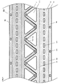
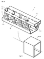
- Figure 1 shows two punched out of a sheet 100 identical device parts 1A, 1B, which are provided for producing a mounting profile 1.
- a first and a second bending line B1 or B2 are shown, by which the device parts 1A, 1B are divided into three areas 11, 12 and 13.
- the first bending line B1 separates a first and a second side element 11, 12 provided with mounting openings 121 from one another.
- a strip-like flange 13 is separated from the second side member 12.
- Second connecting elements or openings 131 are provided on the flange element 13 of the first device part 1A, which correspond to first connecting elements 112 provided on the first side element 11 of the second device part 1B.
- the first side elements 11 of the two device parts 1A, 1B are provided with interlocking triangles 110, from which openings 111 are cut out.
- the precise mutual sawtooth cutting allows the use of a narrow sheet metal strip 100 and thus the reduction of material costs and weight and the avoidance of material losses.
- Figure 13 As shown in Figure 13, of course, other more or less intermeshing or peripherally adjoining, for example, rectangular or trapezoidal shapes are selected.
- the two device parts 1A, 1B can be stamped with said elements with minimal effort in a single step from the sheet 100, the thickness of which is selected according to the strength required for the mounting profile to be produced. Typically, a galvanized sheet is selected with a thickness of a few millimeters.
- FIG. 2 shows the two device parts 1A, 1B of FIG. 1, which are still interlocked but separated by a few millimeters.
- FIG. 3 shows one of the device parts 1A, 1B in a spatial view with the first bending line B1 about which the two side elements 11, 12 are bent against each other, and with the second bending line B2 around which the flange element 13 is angled against the first side element 12.
- FIG. 4 shows the two finished bent device parts 1A, 1B of FIG. 1 during mutual assembly.
- the two side elements 11, 12 of the device parts 1A, 1B form an L-profile and are complemented by the angled flange 13 to a lobe to a U-profile.
- the first side element 11 of the one device part 1A is connected to the second side element 12 of the other device part 1B such that a hollow rectangular profile is formed, as shown in FIG.
- first side elements 11 and the second side elements 12 each lie in mutually parallel planes.
- the flange members 13 overlap the first side members 11 such that the first and second connecting elements 112, 131 can cooperate.
- the first connection elements 112 provided on the first side elements 11 are tabs or hooks which are cut out of the sheet metal 100 and bent, for example, which can enter into the second connection elements 131 designed as openings and can be anchored there.
- the tabs or hooks introduced into the openings are crimped or locked by means of a locking element 114 (see the embodiment of FIG. 7, for example).
- a stable mounting profile 1 is formed by the two interconnected device parts 1A, 1B, the strength of which can be increased by further measures.
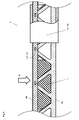
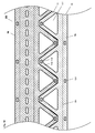
- FIG. 6 shows a section through an inventive mounting profile 1, whose first side elements 111 are provided with openings 111 to which a collar 1111 projecting into the mounting profile 1 adjoins.
- the material of the openings 111 was therefore not cut out, at least not completely, but pressed inwards (or outside) (see, for example, also Figure 9) to reinforce the mounting profile 1.
- the collar 1111 which ensures increased strength even at a depth of a few millimeters, compensates for the cut-out material by a multiple and gives the mounting profile 1 a greatly increased torsional and buckling strength.
- the formation of the collar 1111 can be carried out efficiently in the same operation with the cutting of the two device parts 1A, 1B.
- the first connecting element 112 is clearly visible, which engages as a lug in the second connecting element 131 designed as an opening and can be locked by means of a wedge 114.
- the tab 112 can also be bent or crimped to the side, so that it can not retreat through the opening 131.
- cables and lines can advantageously be laid within the mounting profile 1.
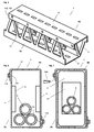
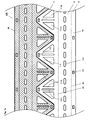
- FIG. 7 shows the mounting profile 1 of FIG. 6 with a stabilization module 2 inserted therein, which has an opening 21 serving to pass through cables or lines 5.
- Stabilization modules 2 are preferably used at locations where external forces act on the mounting profile. Particularly advantageous is the use of hard elastic stabilization modules 2, by which the punctiform acting forces are distributed flat on the mounting profile 1.
- FIG. 8 shows the mounting profile 1 of FIG. 5 under the action of a load F L at a point which is reinforced by means of an inner stabilization module 2.
- FIG. 8 also shows a sleeve-shaped outer stabilization module 20, 200 which comprises and stabilizes the mounting profile 1 in a form-fitting manner.
- the outer stabilization module 20, 200 can also serve as an end module, which completes the mounting profile 1 aesthetically and / or functionally advantageous.
- FIG. 9 shows two identical device parts 1A, 1B punched out of a metal sheet 100, on which simpler first connecting elements 112 'are provided.
- the first connection elements 112 ' consist of plate-shaped end pieces, which are attached to the triangles 110 of the first side elements 111.
- FIG. 11 shows an outer stabilization or end module 20, 200 serving to receive the mounting profile 1 of FIG.
- FIG. 12 shows two non-identical device parts 1A, 1B which are punched out of a sheet metal 100 and are provided for producing a mounting profile 1 which has a hollow profile with a triangular cross-section.
- the second side member 12 is completely missing.
- FIG. 13 shows a device part 1A, 1B with rectangular tooth elements 110 with rectangular, projecting openings 111.
- FIG. 14 schematically shows three mounting profiles 1 produced by means of the device parts 1A, 1B of FIG. 12, which are connected to one another in a form-fitting manner by means of openings 111 and collar 1111 and by means of a connecting element 2000.
- FIG. 15 shows the device parts 1A, 1B of FIG. 1 with preferably configured triangular toothed elements 110, which have two approximately triangular perforations or openings 111A, 111B arranged symmetrically to one another, in the axis of symmetry of which a web 1110 is arranged, which considerably increases the tooth elements 110 Gives strength. To increase the strength of the web 1110, this is provided with a bead 1111 or press-fit. The only an insignificantly larger production costs causing Device parts 1A, 1B of Figure 15 therefore have a much higher strength.
- the inventive mounting profile 1 has been described and illustrated in preferred embodiments. On the basis of the teaching according to the invention, however, further expert designs can be realized. In particular, any desired configurations of the first and second side elements 11, 12 and of the first and second connection elements 112 (112 '), 131 can be realized. To reinforce the mounting profile 1 further structural elements such as bends or beads can be provided. The openings 111 in the side elements 11, 12 can be configured in such a way that mounting profiles 1 according to the invention can easily be coupled, so that suspended ceilings can be realized on the basis of the mounting profiles 1.
- the inventive mounting profile 1 can of course also be used as a pillar, which is coupled for example with a suspended ceiling.
- lighter or heavy loads such as lights, tracks, etc., can be laid and mounted.
- each mounting profiles 1 are used, which are suitable for carrying the maximum loads occurring.
- connection of the two device parts 1A and 1B is preferably carried out with the described means of connecting elements 112, 131; 112 ', 131.
- connecting elements 112, 131; 112 ', 131 rivet connections, screw connections, welded connections and / or toxic compounds are also possible and often advantageously applicable.
- the device parts 1A and 1B are mutually fixed by means of spot welding, screws or clamps, after which the rivet or tox compounds are created.
Abstract
Description
Die Erfindung betrifft ein Montageprofil nach dem Oberbegriff des Patentanspruchs 1.The invention relates to a mounting profile according to the preamble of
Wesentliche Konstruktionselemente in Gebäuden sind Montageprofile, insbesondere Träger oder stabförmige Bauteile, wie sie in [1],
Nachteilig bei diesen Trägern sind deren Gewicht und der auf die Tragfunktion beschränkte Nutzen.A disadvantage of these carriers are their weight and limited to the support function benefits.
Der vorliegenden Erfindung liegt daher die Aufgabe zugrunde, ein verbessertes Montageprofil zu schaffen. Insbesondere ist ein leichteres und vielseitiger verwendbares Montageprofil zu schaffen.The present invention is therefore based on the object to provide an improved mounting profile. In particular, a lighter and versatile usable mounting profile is created.
Diese Aufgabe wird mit einem Montageprofil gelöst, welches die in Anspruch 1 angegebenen Merkmale aufweist. Vorteilhafte Ausgestaltungen der Erfindung sind in weiteren Ansprüchen angegeben.This object is achieved with a mounting profile having the features specified in
Das Montageprofil, das insbesondere dem Tragen von Lasten und/oder der Führung von Kabel dient, besteht einem ersten und einem zweiten stabförmigen Vorrichtungsteil, die formschlüssig derart miteinander verbunden sind, dass ein tragfähiges Hohlprofil mit rechteckigem, dreieckigem oder trapezoidem Querschnitt gebildet wird, und die peripher zueinander korrespondierende erste Seitenelemente aufweisen, die über ein am ersten und/oder zweiten Vorrichtungsteil vorgesehenes zweites Seitenelement miteinander verbunden sind.The mounting profile, which in particular serves to carry loads and / or the guidance of cables, consists of a first and a second rod-shaped device part, which are positively connected to each other in such a way that a load-bearing hollow profile with rectangular, triangular or trapezoidal Cross-section is formed, and have the peripheral mutually corresponding first side elements, which are interconnected via a provided on the first and / or second device part second side member.
In vorzugsweisen Ausgestaltungen sind die beiden Vorrichtungsteile oder die ersten und/oder zweiten Seitenelemente der beiden Vorrichtungsteile identisch ausgestaltet, gegebenenfalls jedoch mit unterschiedlichen Öffnungen versehen.In preferred embodiments, the two device parts or the first and / or second side elements of the two device parts are configured identically, but optionally provided with different openings.
Die beiden Vorrichtungsteile werden vorzugsweise aus einem Blechstück geschnitten, wobei die ersten Seitenelemente der beiden Vorrichtungsteile innerhalb des Blechstücks entlang einer Peripherielinie verzahnend ineinander eingreifen. Die beiden Vorrichtungsteile können daher ohne Materialverluste in einem Arbeitsgang gefertigt werden. Das Montageprofil, das mit wenigen Handgriffen durch Zusammensetzen und Verbinden der beiden Vorrichtungsteile hergestellt werden kann, wird Material sparend befestigt, weist ein geringes Gewicht auf, ist innen gut zugänglich und universell einsetzbar. Durch die Wahl identischer Vorrichtungsteile kann die die Produktion und Montage weiter vereinfacht werden.The two parts of the device are preferably cut from a piece of sheet metal, wherein the first side elements of the two parts of the device within the sheet metal piece interlocking with each other along a peripheral line. The two parts of the device can therefore be manufactured without loss of material in one operation. The mounting profile, which can be made with a few simple steps by assembling and connecting the two parts of the device, is attached to save material, has a low weight, is easily accessible on the inside and universally applicable. By choosing identical parts of the device, the production and assembly can be further simplified.
In vorzugsweisen Ausgestaltungen ist wenigstens eines der Seitenelemente mit Strukturelementen erhöhter Festigkeit, beispielsweise mit einer Reihe von Öffnungen versehen, die je durch einen in das Montageprofil hinein ragenden Kragen begrenzt sind. Durch die gefertigten Kragen erhält das betreffende Seitenelement und somit das Montageprofil eine erhöhte Festigkeit. Durch die Öffnungen können zudem Kabel und Leitungen zu- und weggeführt werden. Ferner können in die Öffnungen auch Ausleger und Verbindungselemente eingesetzt werden. Die Öffnungen können eingestanzt werden, wobei die Öffnungsränder angehalst werden, um den erwünschten Kragen zu bilden.In preferred embodiments, at least one of the side elements is provided with structural elements of increased strength, for example with a series of openings which are each bounded by a projecting into the mounting profile collar. Due to the manufactured collar receives the relevant side element and thus the mounting profile increased strength. Cables and cables can also be fed in and out through the openings. Furthermore, cantilevers and connecting elements can also be used in the openings. The openings may be stamped with the opening edges being stopped to form the desired collar.
An den äusseren Enden sind die Seitenelemente der beiden Vorrichtungsteile mit ersten und zweiten Verbindungselementen versehen, mittels derer die beiden Vorrichtungsteile formschlüssig miteinander verbunden werden können.At the outer ends, the side elements of the two device parts are provided with first and second connecting elements, by means of which the two device parts can be positively connected with each other.
Beispielsweise können die ersten Verbindungselemente ausgeschnittene und gebogene, ein- oder beidseitig gehaltene Laschen oder Endstücke sein, die in die als Öffnungen ausgestalteten zweiten Verbindungselemente einführbar und gegebenenfalls durch Biegen oder Pressen oder mittels eines Arretierelements arretierbar sind. Als erste Verbindungselemente dienende Endstücke, die in eine Öffnung am gegenüberliegenden Vorrichtungsteil einführbar sind, sind am ersten Seitenelement besonders vorteilhaft realisierbar, da dafür nur eine entsprechende Anpassung des Verlaufs des Schnitts notwendig ist, mittels dessen die beiden Vorrichtungsteile voneinander getrennt werden. Bei dieser Ausgestaltung können die beiden Vorrichtungsteile auch besonders einfach miteinander verbunden werden, da die Endstücke in die Richtung zeigen, in die die Vorrichtungsteile gegeneinander geführt werden, und somit automatisch in die zweiten Verbindungselemente eingreifen.For example, the first connecting elements may be cut-out and curved tabs or end pieces held on one or both sides, which can be introduced into the second connecting elements configured as openings and optionally locked by bending or pressing or by means of a locking element. End pieces serving as first connecting elements, which can be introduced into an opening on the opposite device part, can be realized particularly advantageously on the first side element, since only a corresponding adaptation of the profile of the section is necessary, by means of which the two device parts are separated from one another. In this embodiment, the two parts of the device can also be connected to each other particularly easily, since the end pieces point in the direction in which the device parts are guided against each other, and thus automatically engage in the second connecting elements.
Die ersten und/oder zweiten Seitenelemente können ferner ein gegebenenfalls unterteiltes Flanschelement aufweisen, das abgewinkelt das anschliessende Seitenelement überlappt und gegebenenfalls mit den ersten oder zweiten Verbindungselementen versehen ist.The first and / or second side elements can furthermore have an optionally divided flange element which, at an angle, overlaps the adjoining side element and is optionally provided with the first or second connecting elements.
Die ersten Seitenelemente der beiden Vorrichtungsteile sind vorzugsweise derart mit einer Reihe von Zahnelementen, beispielsweise Dreiecken versehen, dass sie unterbruchsfrei ineinander verzahnt und somit auch in einfacher Weise, nur durch einen entsprechend verlaufenden Schnitt, aus einem Blechstück geschnitten oder gestanzt werden können.The first side elements of the two device parts are preferably provided with a series of toothed elements, such as triangles, that they interlock without interruption and thus can be cut or punched in a simple manner, only by a correspondingly extending section of a piece of sheet metal.
In vorzugsweisen Ausgestaltungen ist innerhalb oder ausserhalb des Montageprofils wenigstens ein block- oder rohrförmiges; starres oder hartelastisches Stabilisierungs-, End-, Kopplungs- oder Verbindungsmodul aus Metall, Holz oder Kunststoff vorgesehen, das zumindest teilweise formschlüssig an das Montageprofil anschliesst und durch das ein ästhetischer oder funktionaler Abschluss des Montageprofils, eine Ankopplung an weitere Montageprofile oder Montageelemente, oder eine Bündelung mehrer Montageprofile ermöglicht wird, durch die eine individuelle Adaption an verschiedne Lasten möglich ist.In preferred embodiments is within or outside the mounting profile at least one block or tubular; rigid or hard-elastic stabilization, end, coupling or connection module made of metal, wood or plastic provided that connects at least partially positively to the mounting profile and by the aesthetic or functional completion of the mounting profile, a coupling to other mounting profiles or mounting elements, or a Bundling of several mounting profiles is made possible through which an individual adaptation to different loads is possible.
Zur Bündelung von Montageprofilen sind daran vorzugsweise Elemente, wie entsprechend ausgestaltete Öffnungen und Kragen, oder Haken, etc., vorgesehen, die die formschlüssige Kopplung mehrerer Montageprofile erlauben oder zumindest unterstützen.To bundle mounting profiles are preferably elements, such as appropriately designed openings and collar, or hooks, etc., provided that allow the positive coupling of several mounting profiles or at least support.
Nachfolgend wird die Erfindung, einschliesslich weiterer vorzugsweiser Ausgestaltungen, anhand von Zeichnungen beispielsweise näher erläutert. Dabei zeigt:
Figur 1- zwei aus einem
Blech 100 ausgestanzteidentische Vorrichtungsteile Montageprofils 1 vorgesehen sind; Figur 2- die beiden ineinander verzahnten und um wenige Millimeter voneinander
getrennten Vorrichtungsteile Figur 1, die mit zueinanderkorrespondierenden Verbindungselementen - Figur 3
- eines der
Vorrichtungsteile Figur 1 in räumlicher Ansicht; - Figur 4
- die beiden fertig
gebogenen Vorrichtungsteile Figur 1 beim gegenseitigen Zusammensetzen; Figur 5- ein
erfindungsgemässes Montageprofil 1, das durch die zusammengesetzten und miteinanderverbundenen Vorrichtungsteile - Figur 6
- ein Schnitt durch ein
erfindungsgemässes Montageprofil 1, das mitauskragenden Öffnungen 111 versehen ist und in dem Kabel oderLeitungen 5 verlegt sind; - Figur 7
- das
Montageprofil 1 von Figur 6 mit einem darineingesetzten Stabilisierungsmodul 2, das eine der Durchführung von Kabel oderLeitungen 5dienende Öffnung 21 aufweist; - Figur 8
- das
Montageprofil 1 vonFigur 5 unter Last mit eineminneren Stabilisierungsmodul 2 und einem äusseren Stabilisierungs- Kopplungs- oder Endmodul 20, 200; - Figur 9
- zwei aus einem
Blech 100 ausgestanzteidentische Vorrichtungsteile Figur 10- das aus den
Vorrichtungsteilen bestehende Montageprofil 1 beim Verschliessen der Verbindungselemente 112'; Figur 11- ein zur Aufnahme des
Montageprofils 1 dienendes Stabilisierungs- Kopplungs- oder Endmodul 20, 200; Figur 12- zwei aus einem
Blech 100 ausgestanzte nichtidentische Vorrichtungsteile Montageprofils 1 vorgesehen sind, das ein Hohlprofil mit dreieckigem Querschnitt aufweist; Figur 13- in räumlicher Ansicht ein
Vorrichtungsteil erstes Seitenelement 11rechteckige Zahnelemente 110 aufweist; - Figur 14
- drei mittels der
Vorrichtungsteile Figur 12gefertigte Montageprofile 1, die mittelsÖffnungen 111, undKragen 1111 sowie mittels einesVerbindungselements 2000 formschlüssig miteinander verbunden sind; und - Fig. 15
- die
Vorrichtungsteile Figur 1 mit vorzugsweise ausgestaltetendreieckigen Zahnelementen 110.
- FIG. 1
- two
identical device parts metal sheet 100, which are provided for producing amounting profile 1; - FIG. 2
- the two interlocking and separated by a few
millimeters device parts elements - FIG. 3
- one of the
device parts - FIG. 4
- the two finished
bent device parts - FIG. 5
- an
inventive mounting profile 1, which is formed by the assembled andinterconnected device parts - FIG. 6
- a section through an
inventive mounting profile 1, which is provided with projectingopenings 111 and are laid in the cable orlines 5; - FIG. 7
- the mounting
profile 1 of Figure 6 with astabilization module 2 inserted therein, which has anopening 21 for the implementation of cables orlines 5; - FIG. 8
- the mounting
profile 1 of Figure 5 under load with aninner stabilization module 2 and an outer stabilization coupling or end module 20, 200; - FIG. 9
- two
identical device parts metal sheet 100, on which simpler connecting elements 112 'are provided; - FIG. 10
- 9 consisting of the
device parts profile 1 when closing the connecting elements 112 '; - FIG. 11
- a stabilization coupling or end module 20, 200 serving to receive the mounting
profile 1; - FIG. 12
- two
non-identical device parts sheet metal 100, which are provided for producing a mountingprofile 1, which has a hollow profile with a triangular cross-section; - FIG. 13
- in spatial view, a
device part first side member 11 hasrectangular tooth elements 110; - FIG. 14
- three mounting
profiles 1 produced by means of thedevice parts openings 111, andcollar 1111 and by means of a connectingelement 2000; and - Fig. 15
- the
device parts
Figur 1 zeigt zwei aus einem Blech 100 ausgestanzte identische Vorrichtungsteile 1A, 1B, die zur Herstellung eines Montageprofils 1 vorgesehen sind. In jedem der beiden Vorrichtungsteile 1A, 1B sind eine erste und eine zweite Biegelinie B1 bzw. B2 eingezeichnet, durch die die Vorrichtungsteile 1A, 1B in drei Bereiche 11, 12 und 13 unterteilt sind. Die erste Biegelinie B1 trennt ein erstes und ein zweites, mit Montageöffnungen 121 versehenes Seitenelement 11, 12 voneinander. Durch die zweite Biegelinie B2 wird ein streifenartiges Flanschelement 13 vom zweiten Seitenelement 12 getrennt. Auf dem Flanschelement 13 des ersten Vorrichtungsteils 1A sind zweite Verbindungselemente bzw. Öffnungen 131 vorgesehen, die zu ersten Verbindungselementen 112 korrespondieren, die am ersten Seitenelement 11 des zweiten Vorrichtungsteils 1B vorgesehen sind. Die ersten Seitenelemente 11 der beiden Vorrichtungsteile 1A, 1B sind mit ineinander verzahnten Dreiecken 110 versehen, aus denen Öffnungen 111 ausgeschnitten sind. Das präzise gegenseitige sägezahnartige Schneiden erlaubt die Verwendung eines schmalen Blechstreifens 100 und somit die Reduktion von Materialaufwand und Gewicht sowie die Vermeidung von Materialverlusten. Wie in Figur 13 gezeigt, können selbstverständlich auch andere mehr oder weniger ineinander eingreifende bzw. peripher aneinander anschliessende, beispielsweise rechteckige oder trapezoide Formen gewählt werden.Figure 1 shows two punched out of a
Aus Figur 1 ist ersichtlich, dass die beiden Vorrichtungsteile 1A, 1B mit den genannten Elementen mit minimalem Aufwand in einem einzigen Arbeitsschritt aus dem Blech 100 ausgestanzt werden können, dessen Dicke entsprechend der Festigkeit gewählt wird, die für das herzustellende Montageprofil erforderlich ist. Typischerweise wird ein verzinktes Blech mit einer Dicke von wenigen Millimetern gewählt.From Figure 1 it can be seen that the two
Figur 2 zeigt die beiden noch ineinander verzahnten, aber um wenige Millimeter voneinander getrennten Vorrichtungsteile 1A, 1B von Figur 1.FIG. 2 shows the two
Figur 3 zeigt eines der Vorrichtungsteile 1A, 1B in räumlicher Ansicht mit der ersten Biegelinie B1, um die die beiden Seitenelemente 11, 12 gegeneinander gebogen werden, und mit der zweiten Biegelinie B2, um die das Flanschelement 13 gegen das erste Seitenelement 12 abgewinkelt wird.FIG. 3 shows one of the
Figur 4 zeigt die beiden fertig gebogenen Vorrichtungsteile 1A, 1B von Figur 1 beim gegenseitigen Zusammensetzen. Die beiden Seitenelemente 11, 12 der Vorrichtungsteile 1A, 1B bilden ein L-Profil und werden durch das abgewinkelte Flanschelement 13 ansatzweise zu einem U-Profil ergänzt.FIG. 4 shows the two finished
Beim Zusammensetzen der beiden identischen Vorrichtungsteile 1A, 1B wird das erste Seitenelement 11 des einen Vorrichtungsteils 1A mit dem zweiten Seitenelement 12 des anderen Vorrichtungsteils 1B derart verbunden, dass ein hohles Rechteckprofil gebildet wird, wie es in Figur 5 gezeigt ist.When assembling the two
Bei dem in Figur 5 gezeigten Montageprofil 1 liegen die ersten Seitenelemente 11 und die zweiten Seitenelemente 12 je in zueinander parallelen Ebenen. Die Flanschelemente 13 überlappen die ersten Seitenelemente 11 derart, dass die ersten und zweiten Verbindungselemente 112, 131 zusammenwirken können. Die an den ersten Seitenelementen 11 vorgesehenen ersten Verbindungselemente 112 sind beispielsweise aus dem Blech 100 ausgeschnittene und gebogene Laschen oder Haken, die in die als Öffnungen ausgebildeten zweiten Verbindungselemente 131 eintreten und dort verankert werden können. Beispielsweise werden die in die Öffnungen eingeführten Laschen oder Haken verpresst oder mittels eines Arretierelements 114 arretiert (siehe die beispielsweise Ausgestaltung von Figur 7).In the case of the mounting
Nach der Arretierung der miteinander gekoppelten Verbindungselemente 112, 131 wird durch die beiden miteinander verbundenen Vorrichtungsteile 1A, 1B ein stabiles Montageprofil 1 gebildet, dessen Festigkeit durch weitere Massnahmen erhöht werden kann.After the locking of the interconnected connecting
Figur 6 zeigt einen Schnitt durch ein erfindungsgemässes Montageprofil 1, dessen erste Seitenelemente 111 mit Öffnungen 111 versehen sind, an die ein in das Montageprofil 1 hineinragender Kragen 1111 anschliesst. Das Material der Öffnungen 111 wurde daher nicht, zumindest nicht vollständig, ausgeschnitten, sondern nach innen (oder aussen) gepresst (siehe z.B. auch Figur 9), um das Montageprofil 1 zu verstärken. Der Kragen 1111, der bereits bei einer Tiefe von wenigen Millimetern eine erhöhte Festigkeit gewährleistet, kompensiert das ausgeschnittene Material um ein mehrfaches und verleiht dem Montageprofil 1 eine stark erhöhte Torsions- und Knickfestigkeit. Die Ausformung der Kragen 1111 kann rationell im selben Arbeitsgang mit dem Schneiden der beiden Vorrichtungsteile 1A, 1B durchgeführt werden.FIG. 6 shows a section through an
In Figur 6 und Figur 7 ist ferner das erste Verbindungselement 112 gut ersichtlich, das als Lasche in das als Öffnung ausgestaltete zweite Verbindungselement 131 eingreift und mittels eines Keils 114 arretierbar ist. Alternativ kann die Lasche 112 auch zur Seite gebogen oder verpresst werden, so dass sie nicht mehr durch die Öffnung 131 zurückweichen kann. Ferner ist gezeigt, dass innerhalb des Montageprofils 1 vorteilhaft Kabel und Leitungen verlegt werden können.In FIG. 6 and FIG. 7, furthermore, the first connecting
Figur 7 zeigt das Montageprofil 1 von Figur 6 mit einem darin eingesetzten Stabilisierungsmodul 2, das eine der Durchführung von Kabel oder Leitungen 5 dienende Öffnung 21 aufweist. Stabilisierungsmodule 2 werden vorzugsweise an Stellen eingesetzt an denen Kräfte von aussen auf das Montageprofil einwirken. Besonders vorteilhaft ist die Verwendung von hartelastischen Stabilisierungsmodulen 2, durch die die punktuell einwirkenden Kräfte flächig auf das Montageprofil 1 verteilt werden.FIG. 7 shows the mounting
Figur 8 zeigt das Montageprofil 1 von Figur 5 unter Einwirkung einer Last FL an einer Stelle, die mittels eines inneren Stabilisierungsmoduls 2 verstärkt ist. In Figur 8 ist ferner ein hülsenförmiges äusseres Stabilisierungsmodul 20, 200 gezeigt, das das Montageprofil 1 formschlüssig umfasst und stabilisiert. Das äussere Stabilisierungsmodul 20, 200 kann ferner als Endmodul dienen, welches das Montageprofil 1 ästhetisch und/oder funktional vorteilhaft abschliesst.FIG. 8 shows the mounting
Figur 9 zeigt zwei aus einem Blech 100 ausgestanzte identische Vorrichtungsteile 1A, 1B, an denen einfacher ausgestaltete erste Verbindungselemente 112' vorgesehen sind. Die ersten Verbindungselemente 112' bestehen aus plattenförmigen Endstücken, welche an den Dreiecken 110 der ersten Seitenelemente 111 angefügt sind.FIG. 9 shows two
Nach dem Biegen der Vorrichtungsteile 1A, 1B können diese besonders einfach miteinander verbunden werden, da die ersten Verbindungselemente 112' bzw. die plattenförmigen Endstücke geradlinig durch die als Öffnungen ausgestalteten zweiten Verbindungselemente 131 hindurch gestossen werden können und lediglich noch abgebogen werden müssen, wie dies in Figur 10 gezeigt ist.After bending the
Figur 11 zeigt ein der Aufnahme des Montageprofils 1 von Figur 10 dienendes äusseres Stabilisierungs- oder Endmodul 20, 200.FIG. 11 shows an outer stabilization or end module 20, 200 serving to receive the mounting
Figur 12 zeigt zwei aus einem Blech 100 ausgestanzte nicht identische Vorrichtungsteile 1A, 1B, die zur Herstellung eines Montageprofils 1 vorgesehen sind, das ein Hohlprofil mit dreieckigem Querschnitt aufweist. Beim ersten Vorrichtungsteil 1A fehlt das zweite Seitenelement 12 vollständig. Durch entsprechende Wahl eines zweiten Seitenelements 12 kann jedoch auch ein Hohlprofil mit trapezoidem Querschnitt gefertigt werden.FIG. 12 shows two
Figur 13 zeigt ein Vorrichtungsteil 1A, 1B mit rechteckförmigen Zahnelementen 110 mit rechteckförmigen, auskragenden Öffnungen 111.FIG. 13 shows a
Figur 14 zeigt schematisch drei mittels der Vorrichtungsteile 1A, 1B von Figur 12 gefertigte Montageprofile 1, die mittels Öffnungen 111 und Kragen 1111 sowie mittels eines Verbindungselements 2000 formschlüssig miteinander verbunden sind. Durch die Bündelung mehrerer Montageprofile 1 können daher Tragstrukturen realisiert werden, die individuell an verschiedene Lasten anpassbar sind. Durch die ineinander greifenden Öffnungen 111 und Kragen 1111 resultiert eine optimale Kopplung der einzelnen Montageprofile 1 und somit eine gleichmässige Lastaufteilung.FIG. 14 schematically shows three mounting
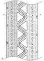
Figur 15 zeigt die Vorrichtungsteile 1A, 1B von Figur 1 mit vorzugsweise ausgestalteten dreieckigen Zahnelementen 110, die zwei symmetrisch zueinander angeordnete, annähernd dreieckige Lochungen oder Öffnungen 111A, 111B aufweisen, in deren Symmetrieachse ein Steg 1110 angeordnet ist, der den Zahnelementen 110 eine wesentlich höhere Festigkeit verleiht. Um die Festigkeit des Steg 1110 zu erhöhen, ist dieser mit einer Sicke 1111 oder Einpressung versehen. Die nur einen unwesentlich grösseren Herstellungsaufwand verursachenden Vorrichtungsteile 1A, 1B von Figur 15 weisen daher eine wesentlich höhere Festigkeit auf.FIG. 15 shows the
Das erfindungsgemässe Montageprofil 1 wurde in bevorzugten Ausgestaltungen beschrieben und dargestellt. Anhand der erfindungsgemässen Lehre sind jedoch weitere fachmännische Ausgestaltungen realisierbar. Insbesondere sind beliebige Ausgestaltungen der ersten und zweiten Seitenelemente 11, 12 und der ersten und zweiten Verbindungselemente 112 (112'), 131 realisierbar. Zur Verstärkung des Montageprofils 1 können weitere strukturelle Elemente wie Biegungen oder Sicken vorgesehen werden. Die Öffnungen 111 in den Seitenelementen 11, 12 können derart ausgestaltet werden, dass erfindungsgemässe Montageprofile 1 leicht koppelbar sind, so dass anhand der Montageprofile 1 abgehängte Decken realisierbar sind. Durch die Öffnungen 111 in den Seitenelementen 11, 12 können Kabel und Leitungen zu und weggeführt werden, was insbesondere für abgehängte Decken besonders vorteilhaft ist, an denen, gegebenenfalls in Labors, Büros oder Verkaufsstellen, beispielsweise Arbeitsplätze punktuell mit Energie- und Datenleitungen zu versorgen sind. Das erfindungsgemässe Montageprofil 1 kann selbstverständlich auch als Säule verwendet werden, die beispielsweise mit einer abgehängten Decke gekoppelt ist. In der abgehängten Decke können leichtere oder schwere Lasten, beispielsweise Lampen, Stromschienen, etc., verlegt und montiert werden. Je nach Anwendung werden jeweils Montageprofile 1 verwendet, welche die zum Tragen der maximal auftretenden Lasten geeignet sind.The
Die Verbindung der beiden Vorrichtungsteile 1A und 1B erfolgt vorzugsweise mit den beschriebenen mittels Verbindungselementen 112, 131; 112', 131. Möglich und oft vorteilhaft anwendbar sind jedoch auch Nietverbindungen, Schraubverbindungen, Schweissverbindungen und/oder Toxverbindungen. Betreffend die Fertigung von Toxverbindungen, die beispielsweise mittels Zangen realisierbar sind, siehe beispielsweise die TOX®-Blechverbindungssysteme der TOX® PRESSOTECHNIK GmbH & Co. KG, D-88250 Weingarten. Möglich ist natürlich die Kombination von Verbindungstechniken. Beispielsweise werden die Vorrichtungsteile 1A und 1B mittels Punktschweissen, Schrauben oder Klammern gegenseitig fixiert, wonach die Niet- oder Toxverbindungen erstellt werden.The connection of the two
Claims (11)
Applications Claiming Priority (1)
| Application Number | Priority Date | Filing Date | Title |
|---|---|---|---|
| CH6772005 | 2005-04-14 |
Publications (2)
| Publication Number | Publication Date |
|---|---|
| EP1712697A2 true EP1712697A2 (en) | 2006-10-18 |
| EP1712697A3 EP1712697A3 (en) | 2007-12-05 |
Family
ID=35520765
Family Applications (1)
| Application Number | Title | Priority Date | Filing Date |
|---|---|---|---|
| EP06405164A Withdrawn EP1712697A3 (en) | 2005-04-14 | 2006-04-12 | Mounting profile |
Country Status (1)
| Country | Link |
|---|---|
| EP (1) | EP1712697A3 (en) |
Cited By (3)
| Publication number | Priority date | Publication date | Assignee | Title |
|---|---|---|---|---|
| WO2011028126A1 (en) * | 2009-09-02 | 2011-03-10 | Øglænd System As | Length profile device |
| US10273690B2 (en) * | 2017-12-26 | 2019-04-30 | Ruhollah SAFARI | Truss composite ceiling with little amount of steel |
| EP4187036A1 (en) * | 2021-11-30 | 2023-05-31 | Kamal Bouaouaja | Support element and method for manufacturing the same |
Citations (4)
| Publication number | Priority date | Publication date | Assignee | Title |
|---|---|---|---|---|
| DE266671C (en) | ||||
| US3626653A (en) | 1969-11-18 | 1971-12-14 | Arsham Amirikian | Biserrated framing member |
| AU465125B2 (en) | 1970-08-11 | 1975-09-01 | Improvements in or relating to structural members | |
| EP0232099A2 (en) | 1986-01-25 | 1987-08-12 | Alpha-Kem Limited | Box-section building element |
Family Cites Families (6)
| Publication number | Priority date | Publication date | Assignee | Title |
|---|---|---|---|---|
| FR508720A (en) * | 1919-02-05 | 1920-10-21 | George Hutchinson | New improvements to structural elements for beams, columns, etc. |
| FR2218016A5 (en) * | 1973-02-14 | 1974-09-06 | Maymont Paul | |
| US5663527A (en) * | 1994-10-18 | 1997-09-02 | Artwright Technology Sdn Bhd | Stackable conduits with hook and hole clip means |
| EP0732788A1 (en) * | 1995-03-17 | 1996-09-18 | Zurecon Ag | Assembly of a ceiling holder and a bracket |
| WO1999067478A1 (en) * | 1998-06-23 | 1999-12-29 | Rbs Technologies Holding Company Pty. Limited | Elongate structural member |
| CA2404320C (en) * | 2002-09-30 | 2005-02-08 | Ernest R. Bodnar | Steel stud with openings and edge formations and method |
-
2006
- 2006-04-12 EP EP06405164A patent/EP1712697A3/en not_active Withdrawn
Patent Citations (4)
| Publication number | Priority date | Publication date | Assignee | Title |
|---|---|---|---|---|
| DE266671C (en) | ||||
| US3626653A (en) | 1969-11-18 | 1971-12-14 | Arsham Amirikian | Biserrated framing member |
| AU465125B2 (en) | 1970-08-11 | 1975-09-01 | Improvements in or relating to structural members | |
| EP0232099A2 (en) | 1986-01-25 | 1987-08-12 | Alpha-Kem Limited | Box-section building element |
Cited By (10)
| Publication number | Priority date | Publication date | Assignee | Title |
|---|---|---|---|---|
| WO2011028126A1 (en) * | 2009-09-02 | 2011-03-10 | Øglænd System As | Length profile device |
| EP2473685A1 (en) * | 2009-09-02 | 2012-07-11 | Øglænd System AS | Length profile device |
| CN102575471A (en) * | 2009-09-02 | 2012-07-11 | 格勒德系统公司 | Length profile device |
| EP2473685A4 (en) * | 2009-09-02 | 2015-12-09 | Glaend System As | Length profile device |
| CN105544861A (en) * | 2009-09-02 | 2016-05-04 | 格勒德系统公司 | Length profile device |
| US9856646B2 (en) | 2009-09-02 | 2018-01-02 | Øglænd System As | Length profile device |
| CN105544861B (en) * | 2009-09-02 | 2018-06-12 | 格勒德系统公司 | Elongated profile device |
| US10273690B2 (en) * | 2017-12-26 | 2019-04-30 | Ruhollah SAFARI | Truss composite ceiling with little amount of steel |
| EP4187036A1 (en) * | 2021-11-30 | 2023-05-31 | Kamal Bouaouaja | Support element and method for manufacturing the same |
| WO2023099145A1 (en) * | 2021-11-30 | 2023-06-08 | Kamal Bouaouaja | Support element and method for producing same |
Also Published As
| Publication number | Publication date |
|---|---|
| EP1712697A3 (en) | 2007-12-05 |
Similar Documents
| Publication | Publication Date | Title |
|---|---|---|
| EP1238222B1 (en) | Assembly rail formed out of at least one profile element | |
| EP2483492B1 (en) | Thin-walled, cold-formed lightweight structural profile element and method for producing such a profile element | |
| DE102005016175A1 (en) | C-section | |
| EP1461535A1 (en) | Assembling device | |
| EP2783437B1 (en) | Mounting rail for cabinet | |
| DE602005002317T2 (en) | Support with a rectangular cross section for a storage system and a storage system with at least one of the supports described | |
| EP0838426B1 (en) | Door leaf, especially for elevators | |
| EP1712697A2 (en) | Mounting profile | |
| EP2686501A1 (en) | Component assembly and suspension device for supporting rails and method for producing same | |
| EP1388620B1 (en) | Connection element for a mounting system | |
| EP2827043B1 (en) | Method for producing a twin rail and twin rail | |
| EP1743863A1 (en) | Connecting element | |
| WO2022122212A1 (en) | Anchor rail and method for producing an anchor rail | |
| EP0143150A1 (en) | flange coupling | |
| EP0998613B1 (en) | Dowel pin for web reinforcements | |
| EP3561199A1 (en) | Connection element for formworks and method of connecting the formworks | |
| EP2689078B1 (en) | Profiled element and method for producing a profiled element | |
| EP2808960B1 (en) | Device for connecting cable path sections and cable path | |
| DE102008055686A1 (en) | Assembly rail for use with fastening arrangement, has base with bracket protruding from it, where base forms rear side and assembly rail is formed as profile with constant cross-section | |
| WO2022078654A1 (en) | Anchor rail and method for producing an anchor rail | |
| DE102005048243A1 (en) | Profile element and uses of such a profile element | |
| DE60019973T2 (en) | HOLLOW PROFILE | |
| EP4286628A1 (en) | Fastening adapter for double-rod grid mats | |
| WO2023208671A1 (en) | Clinching connection | |
| DE202021104122U1 (en) | Head connector for attaching a hanging support of a cable support system to a ceiling |
Legal Events
| Date | Code | Title | Description |
|---|---|---|---|
| PUAI | Public reference made under article 153(3) epc to a published international application that has entered the european phase |
Free format text: ORIGINAL CODE: 0009012 |
|
| AK | Designated contracting states |
Kind code of ref document: A2 Designated state(s): AT BE BG CH CY CZ DE DK EE ES FI FR GB GR HU IE IS IT LI LT LU LV MC NL PL PT RO SE SI SK TR |
|
| AX | Request for extension of the european patent |
Extension state: AL BA HR MK YU |
|
| PUAL | Search report despatched |
Free format text: ORIGINAL CODE: 0009013 |
|
| AK | Designated contracting states |
Kind code of ref document: A3 Designated state(s): AT BE BG CH CY CZ DE DK EE ES FI FR GB GR HU IE IS IT LI LT LU LV MC NL PL PT RO SE SI SK TR |
|
| AX | Request for extension of the european patent |
Extension state: AL BA HR MK YU |
|
| 17P | Request for examination filed |
Effective date: 20080605 |
|
| AKX | Designation fees paid |
Designated state(s): AT BE BG CH CY CZ DE DK EE ES FI FR GB GR HU IE IS IT LI LT LU LV MC NL PL PT RO SE SI SK TR |
|
| 17Q | First examination report despatched |
Effective date: 20080820 |
|
| STAA | Information on the status of an ep patent application or granted ep patent |
Free format text: STATUS: THE APPLICATION IS DEEMED TO BE WITHDRAWN |
|
| 18D | Application deemed to be withdrawn |
Effective date: 20131101 |