EP1712654A1 - Multi-layer coating having excellent adhesion and sliding properties and production method thereof - Google Patents
Multi-layer coating having excellent adhesion and sliding properties and production method thereof Download PDFInfo
- Publication number
- EP1712654A1 EP1712654A1 EP06006427A EP06006427A EP1712654A1 EP 1712654 A1 EP1712654 A1 EP 1712654A1 EP 06006427 A EP06006427 A EP 06006427A EP 06006427 A EP06006427 A EP 06006427A EP 1712654 A1 EP1712654 A1 EP 1712654A1
- Authority
- EP
- European Patent Office
- Prior art keywords
- layer
- molybdenum disulfide
- coating
- lubricating
- sliding properties
- Prior art date
- Legal status (The legal status is an assumption and is not a legal conclusion. Google has not performed a legal analysis and makes no representation as to the accuracy of the status listed.)
- Granted
Links
Images

Classifications
-
- C—CHEMISTRY; METALLURGY
- C23—COATING METALLIC MATERIAL; COATING MATERIAL WITH METALLIC MATERIAL; CHEMICAL SURFACE TREATMENT; DIFFUSION TREATMENT OF METALLIC MATERIAL; COATING BY VACUUM EVAPORATION, BY SPUTTERING, BY ION IMPLANTATION OR BY CHEMICAL VAPOUR DEPOSITION, IN GENERAL; INHIBITING CORROSION OF METALLIC MATERIAL OR INCRUSTATION IN GENERAL
- C23C—COATING METALLIC MATERIAL; COATING MATERIAL WITH METALLIC MATERIAL; SURFACE TREATMENT OF METALLIC MATERIAL BY DIFFUSION INTO THE SURFACE, BY CHEMICAL CONVERSION OR SUBSTITUTION; COATING BY VACUUM EVAPORATION, BY SPUTTERING, BY ION IMPLANTATION OR BY CHEMICAL VAPOUR DEPOSITION, IN GENERAL
- C23C14/00—Coating by vacuum evaporation, by sputtering or by ion implantation of the coating forming material
- C23C14/06—Coating by vacuum evaporation, by sputtering or by ion implantation of the coating forming material characterised by the coating material
- C23C14/0623—Sulfides, selenides or tellurides
-
- C—CHEMISTRY; METALLURGY
- C23—COATING METALLIC MATERIAL; COATING MATERIAL WITH METALLIC MATERIAL; CHEMICAL SURFACE TREATMENT; DIFFUSION TREATMENT OF METALLIC MATERIAL; COATING BY VACUUM EVAPORATION, BY SPUTTERING, BY ION IMPLANTATION OR BY CHEMICAL VAPOUR DEPOSITION, IN GENERAL; INHIBITING CORROSION OF METALLIC MATERIAL OR INCRUSTATION IN GENERAL
- C23C—COATING METALLIC MATERIAL; COATING MATERIAL WITH METALLIC MATERIAL; SURFACE TREATMENT OF METALLIC MATERIAL BY DIFFUSION INTO THE SURFACE, BY CHEMICAL CONVERSION OR SUBSTITUTION; COATING BY VACUUM EVAPORATION, BY SPUTTERING, BY ION IMPLANTATION OR BY CHEMICAL VAPOUR DEPOSITION, IN GENERAL
- C23C14/00—Coating by vacuum evaporation, by sputtering or by ion implantation of the coating forming material
- C23C14/02—Pretreatment of the material to be coated
- C23C14/027—Graded interfaces
-
- C—CHEMISTRY; METALLURGY
- C23—COATING METALLIC MATERIAL; COATING MATERIAL WITH METALLIC MATERIAL; CHEMICAL SURFACE TREATMENT; DIFFUSION TREATMENT OF METALLIC MATERIAL; COATING BY VACUUM EVAPORATION, BY SPUTTERING, BY ION IMPLANTATION OR BY CHEMICAL VAPOUR DEPOSITION, IN GENERAL; INHIBITING CORROSION OF METALLIC MATERIAL OR INCRUSTATION IN GENERAL
- C23C—COATING METALLIC MATERIAL; COATING MATERIAL WITH METALLIC MATERIAL; SURFACE TREATMENT OF METALLIC MATERIAL BY DIFFUSION INTO THE SURFACE, BY CHEMICAL CONVERSION OR SUBSTITUTION; COATING BY VACUUM EVAPORATION, BY SPUTTERING, BY ION IMPLANTATION OR BY CHEMICAL VAPOUR DEPOSITION, IN GENERAL
- C23C14/00—Coating by vacuum evaporation, by sputtering or by ion implantation of the coating forming material
- C23C14/22—Coating by vacuum evaporation, by sputtering or by ion implantation of the coating forming material characterised by the process of coating
- C23C14/34—Sputtering
- C23C14/3464—Sputtering using more than one target
-
- C—CHEMISTRY; METALLURGY
- C23—COATING METALLIC MATERIAL; COATING MATERIAL WITH METALLIC MATERIAL; CHEMICAL SURFACE TREATMENT; DIFFUSION TREATMENT OF METALLIC MATERIAL; COATING BY VACUUM EVAPORATION, BY SPUTTERING, BY ION IMPLANTATION OR BY CHEMICAL VAPOUR DEPOSITION, IN GENERAL; INHIBITING CORROSION OF METALLIC MATERIAL OR INCRUSTATION IN GENERAL
- C23C—COATING METALLIC MATERIAL; COATING MATERIAL WITH METALLIC MATERIAL; SURFACE TREATMENT OF METALLIC MATERIAL BY DIFFUSION INTO THE SURFACE, BY CHEMICAL CONVERSION OR SUBSTITUTION; COATING BY VACUUM EVAPORATION, BY SPUTTERING, BY ION IMPLANTATION OR BY CHEMICAL VAPOUR DEPOSITION, IN GENERAL
- C23C14/00—Coating by vacuum evaporation, by sputtering or by ion implantation of the coating forming material
- C23C14/22—Coating by vacuum evaporation, by sputtering or by ion implantation of the coating forming material characterised by the process of coating
- C23C14/34—Sputtering
- C23C14/35—Sputtering by application of a magnetic field, e.g. magnetron sputtering
- C23C14/352—Sputtering by application of a magnetic field, e.g. magnetron sputtering using more than one target
-
- Y—GENERAL TAGGING OF NEW TECHNOLOGICAL DEVELOPMENTS; GENERAL TAGGING OF CROSS-SECTIONAL TECHNOLOGIES SPANNING OVER SEVERAL SECTIONS OF THE IPC; TECHNICAL SUBJECTS COVERED BY FORMER USPC CROSS-REFERENCE ART COLLECTIONS [XRACs] AND DIGESTS
- Y10—TECHNICAL SUBJECTS COVERED BY FORMER USPC
- Y10T—TECHNICAL SUBJECTS COVERED BY FORMER US CLASSIFICATION
- Y10T428/00—Stock material or miscellaneous articles
- Y10T428/12—All metal or with adjacent metals
- Y10T428/12493—Composite; i.e., plural, adjacent, spatially distinct metal components [e.g., layers, joint, etc.]
- Y10T428/12535—Composite; i.e., plural, adjacent, spatially distinct metal components [e.g., layers, joint, etc.] with additional, spatially distinct nonmetal component
- Y10T428/12576—Boride, carbide or nitride component
-
- Y—GENERAL TAGGING OF NEW TECHNOLOGICAL DEVELOPMENTS; GENERAL TAGGING OF CROSS-SECTIONAL TECHNOLOGIES SPANNING OVER SEVERAL SECTIONS OF THE IPC; TECHNICAL SUBJECTS COVERED BY FORMER USPC CROSS-REFERENCE ART COLLECTIONS [XRACs] AND DIGESTS
- Y10—TECHNICAL SUBJECTS COVERED BY FORMER USPC
- Y10T—TECHNICAL SUBJECTS COVERED BY FORMER US CLASSIFICATION
- Y10T428/00—Stock material or miscellaneous articles
- Y10T428/12—All metal or with adjacent metals
- Y10T428/12493—Composite; i.e., plural, adjacent, spatially distinct metal components [e.g., layers, joint, etc.]
- Y10T428/12771—Transition metal-base component
- Y10T428/12806—Refractory [Group IVB, VB, or VIB] metal-base component
-
- Y—GENERAL TAGGING OF NEW TECHNOLOGICAL DEVELOPMENTS; GENERAL TAGGING OF CROSS-SECTIONAL TECHNOLOGIES SPANNING OVER SEVERAL SECTIONS OF THE IPC; TECHNICAL SUBJECTS COVERED BY FORMER USPC CROSS-REFERENCE ART COLLECTIONS [XRACs] AND DIGESTS
- Y10—TECHNICAL SUBJECTS COVERED BY FORMER USPC
- Y10T—TECHNICAL SUBJECTS COVERED BY FORMER US CLASSIFICATION
- Y10T428/00—Stock material or miscellaneous articles
- Y10T428/24—Structurally defined web or sheet [e.g., overall dimension, etc.]
- Y10T428/24942—Structurally defined web or sheet [e.g., overall dimension, etc.] including components having same physical characteristic in differing degree
- Y10T428/2495—Thickness [relative or absolute]
- Y10T428/24967—Absolute thicknesses specified
- Y10T428/24975—No layer or component greater than 5 mils thick
-
- Y—GENERAL TAGGING OF NEW TECHNOLOGICAL DEVELOPMENTS; GENERAL TAGGING OF CROSS-SECTIONAL TECHNOLOGIES SPANNING OVER SEVERAL SECTIONS OF THE IPC; TECHNICAL SUBJECTS COVERED BY FORMER USPC CROSS-REFERENCE ART COLLECTIONS [XRACs] AND DIGESTS
- Y10—TECHNICAL SUBJECTS COVERED BY FORMER USPC
- Y10T—TECHNICAL SUBJECTS COVERED BY FORMER US CLASSIFICATION
- Y10T428/00—Stock material or miscellaneous articles
- Y10T428/26—Web or sheet containing structurally defined element or component, the element or component having a specified physical dimension
- Y10T428/263—Coating layer not in excess of 5 mils thick or equivalent
- Y10T428/264—Up to 3 mils
- Y10T428/265—1 mil or less
Definitions
- the present invention relates to a multi-layer coating having excellent adhesion and sliding properties, and production method thereof, which can be applied onto a part surface of tools or similar items, such as a metal die, that are used, for example, in environments ranging from hot to cold.
- solid lubricants have mainly proceeded for intended use in environments wherein lubricating oil could not be easily employed, such as high temperature, extreme low temperature, ultra high pressure, a vacuum and the like.
- solid lubricants there are those which can be applied to parts having a complex shape by being deposited as a coating onto the object to be treated by a process such as physical vapor deposition (PVD) or chemical vapor deposition (CVD).
- PVD physical vapor deposition
- CVD chemical vapor deposition
- Substances such as molybdenum disulfide and diamond-like carbon (DLC) are already being put to practical use.
- molybdenum disulfide is being applied to many sliding parts to improve seize resistance, due to its superior sliding properties and the fact that it can maintain a low friction coefficient even in an air atmosphere of up to several hundred °C.
- a hard layer such as a nitride or a carbonitride which have excellent wear resistance
- a multi-layer coating having excellent sliding properties can be produced which has wear resistance and seize resistance at the same time.
- a method has also been proposed which improves the adhesion and weatherability of a coating by incorporating a metal element into the molybdenum disulfide ( JP-A-2000-001768 ).
- molybdenum disulfide has the drawback of being an extremely soft substance, wich when formed into a coating does not always possess sufficient adhesion with the object to be treated. For this reason, if a molybdenum disulfide coating is applied as is onto a sliding part, there is the serious problem that the coating is susceptible at an initial stage of use to peeling and thereby lost without exhibiting sufficient performance. In addition, molybdenum disulfide also has the drawback that it is highly hygroscopic, which causes lubricating performance to deteriorate.
- JP-A-2000-001768 describes measures against such problems. Namely, because molybdenum disulfide hardens if incorporated with a metal element, adhesion with a part will certainly improve when formed into a coating. However, not only is this adhesive strength not strong enough to be applied to a part which is subject to vigorous sliding, if the ratio of the metal element is too high the excellent lubricating properties that an inherent characteristic of molybdenum disulfide deteriorates.
- the present inventors realized that if, for example, a nitride, carbonitride or other such compound to serve as a hard layer is formed under the molybdenum disulfide layer, which is a sulfide, sufficient adhesion cannot be achieved because the material properties (constituent elements, interatomic bonds, crystal structure etc.) of these layers are substantially different. Further investigation based on this perspective showed that in order to increase the adhesion of a molybdenum disulfide layer, it is preferable to increase the ratio of the metal element in the layer. This investigation also showed that adhesion and sliding properties can both be sufficiently attained in the same layer by gradiently varying the ratio of the metal element in the layer.
- the present inventors showed that the factors influencing the sliding properties of a coating do not only relate to humidity, which had been pointed out in the past, and that oxygen impurities in the layer also have a large influence, thereby arriving at their proposal for an optimal production method for resolving the problems.
- the present invention is a multi-layer coating having excellent adhesion and sliding properties, which comprises a lubricating layer consisting of a metal element and molybdenum disulfide on a hard layer whose main component is a nitride and/or carbonitride comprising one or more elements selected from the group consisting of Ti, V, Zr, Cr, Nb, Si, Al and B, wherein the composition of the lubricating layer is a gradient in which a ratio of the metal element decreases, and a ratio of the molybdenum disulfide increases, going towards the surface from the hard layer side, and wherein a maximum oxygen concentration of the lubricating layer is no greater than 25 atom%.
- the metal element constituting the lubricating layer is preferably Ti.
- a 0.01 ⁇ m or more thick molybdenum disulfide layer is preferably formed on the top surface of the multi-layer coating.
- the present invention further provides a method for producing a multi-layer coating having excellent adhesion and sliding properties, wherein in forming the multi-layer coating, an ion plating source is used for forming the hard layer, a coating source is used for forming the lubricating layer, and at least the molybdenum disulfide contained therein is deposited using a sputtering source, the ion plating source and the coating source being provided in the same chamber, wherein an object held in the chamber, which is to have the multi-layer coating formed thereon is provided with the hard layer formed at a temperature of 380°C or more and subsequently the lubricating layer formed while the object is held in the chamber.
- the temperature of the object to be treated when forming the lubricating layer is preferably no greater than 380°C.
- the ion plating source is preferably an arc discharge type.
- the sputtering source for depositing the molybdenum disulfide preferable either applies a direct current pulse voltage, or is an unbalanced magnetron sputtering source.
- the present invention enables a multi-layer coating having even more excellent adhesion and sliding properties, and production method thereof, to be provided.
- One characteristic of the present invention lies in that the factors for insufficient adhesion in a conventional lubricating coating which utilizes a sulfide are clarified. Specifically, when forming a hard layer of carbonitride or the like as an under layer, the adhesion insufficiency of a molybdenum disulfide layer formed thereabove can be resolved through the reexamination and control of the coating structure across both the layers.
- Another characteristic of the present invention lies in the clarification of the factors behind deterioration in sliding properties that were a problem for conventional lubricating coating which utilized a sulfide. Specifically, in addition to the above-described control of the coating structure, by reexamining the constituents contained in the additionally formed molybdenum disulfide layer (lubricating layer), the inadequacy in sliding properties (seize resistance) can also be resolved.
- the present invention is directed to a multi-layer coating that has excellent sliding properties. These properties are realized by coating a substance, which has even better seize resistance and which exhibits a low friction coefficient, so that it adheres well onto a hard layer which is wear resistant. At this stage it is important that the hard layer which will serve as the underlayer has a nitride and/or carbonitride as a main component that is a high-hardness substance having a Vickers hardness of 1,000 HV or more for handling wear resistance.
- Representative examples of such substances that are often industrially employed include nitrides and carbonitrides comprising one or more elements selected from the group consisting of Ti, V, Zr, Cr, Nb, Si, Al and B.
- the term "main component” means that compounds other than the nitride and/or carbonitride are not excessively present in the hard layer. For example, if oxides or other such compounds are excessively present, the wear resistance which is so important for the hard layer properties according to the present invention deteriorates. Thus, this term is used to mean that the other compounds should be present in such a small amount that does not adversely affect the hard coating. This amount may be such that peaks other than the main component nitride or carbonitride cannot be confirmed by analysis such as X-ray diffraction, for example.
- molybdenum disulfide is the most suitable for the lubricating layer formed on the hard layer.
- molybdenum disulfide is a soft substance, and when made into a layer has the problem that adhesion is poor. Therefore, to improve the adhesion of molybdenum disulfide it is effective to increase the hardness of molybdenum disulfide.
- One such technique is to incorporate a metal element into the molybdenum disulfide.
- the layer friction properties are worse than those for pure molybdenum disulfide.
- it is effective to form the layer so as to manifest a gradient composition, wherein the composition of the lubricating layer has a ratio of molybdenum disulfide which increases and a ratio of metal element which decreases going from the hard layer side towards the surface.
- the term "gradient composition” as used here is defined as the "continuous (or as described below, step-wise) increase or decrease of the chemical composition in a thickness direction".
- a gradient structure of such a composition can be identified by, for example, glow discharge emission spectral analysis (GDS). GDS not only is highly accurate, but has a fast analysis speed, which make it a suitable technique for coating analysis of a thickness of about a few ⁇ m. An example of the analyzed results is shown in Fig. 1.
- the entire multi-layer coating according to the present invention Before explaining the gradient composition of the above-described lubricating layer, the entire multi-layer coating according to the present invention will be explained.
- the analyzed object area is approximately a few mm 2 , which is too broad for the coating thickness of the present invention.
- the layer boundaries do not clearly appear.
- the region to the right of point A is the hard layer.
- the metal (Ti in Fig. 1) increasing from 0 atom% is present on the surface side of such region, although this is not related to the gist of the present invention.
- the composition of the hard layer can be evaluated at any depth which lack the above-described metal.
- the hard layer in the case of Fig. 1 consists of CrN.
- the top surface layer comprising the molybdenum disulfide monolayer which will be described later, has an interface with the lubricating layer, which may be defined as the "depth where the metal element of the lubricating layer disappears" (point B).
- the lubricating layer will now be explained.
- Fig. 1 it can be seen that the contained metal Ti content continuously decreases going from point A, which is the lubricating layer start point, towards the surface, while the S content which makes up the molybdenum disulfide continuously increases, thereby achieving the gradient composition according to the present invention.
- the gradient composition according to the present invention can preferably be quantitatively defined by the metal content curve for which a clear content profile can be easily obtained.
- a preferable state is where the gradient between two points separated by a distance of 0.2 ⁇ m at any section of the metal content curve in the lubricating layer region (between points A and B) is never less than 20, and, similarly, the gradient between two points separated by a distance of 0.05 ⁇ m is never greater than 350. It can be seen that in Fig. 1 the decreasing profile of the Ti in the lubricating layer satisfies these defined values.
- the oxygen concentration in the lubricating layer is stipulated because the frictional properties of molybdenum disulfide are largely dependent on the contained oxygen concentration, and not just on the contained moisture. If the oxygen concentration is large, the inherent excellent seize resistance is not sufficiently exhibited.
- the oxygen concentration detected in the layer thickness direction of the lubricating layer must not exceed a maximum of 25 atom%. Preferably, the concentration does not exceed 20 atom%, and more preferably does not exceed 18 atom%. If the oxygen concentration does exceed 25 atom%, the lubricating layer becomes brittle, whereby peeling can easily occur.
- the oxygen concentration can be determined by GDS analysis. In Fig. 1 the maximum oxygen concentration is 18 atom% (point C).
- the metal element content in the lubricating layer preferably has at least 60 atom%. More preferable is 70 atom% or more (including essentially 100 atom%). In Fig. 1, a Ti amount of 80 atom% can be read (point A).
- the metal element content at the surface is preferably no greater than 10 atom%, and more preferably no greater than 5 atom%. It can be noted that, further above that layer, the metal element Ti was not found in the below-described molybdenum disulfide monolayer forming the multi-layer coating illustrated in Fig. 1.
- Ti was used as an example when explaining the metal element species which along with molybdenum disulfide forms the lubricating layer, this does not particularly limit the elemental species as regards the effect for securing adhesion with the hard layer of the underlayer. It has been confirmed that when one or more of Ti, V, Zr and Cr are selected, good layer adhesion and sufficient sliding properties can be attained. Of these, it has been confirmed that Ti can achieve the most stable adhesion and sliding properties.
- the above-described metal element which along with molybdenum disulfide constitutes the lubricating layer, is added for the purpose of improving layer adhesion. From the perspective of the inherent lubricating properties, it would be preferable if the metal element was not present.
- a pure molybdenum disulfide layer is susceptible to abrasion from sliding, such a pure layer exhibits an effect of adapting the parts together at the initial stage of sliding.
- the molybdenum disulfide layer at the top surface is preferably present in a thickness of 0.01 ⁇ m or more. Although there are no upper limits stipulated for the thickness, because there is the risk that layer adhesion will deteriorate if formed with a more than necessary thickness, an upper limit can be set at about 0.2 ⁇ m.
- the multi-layer coating according to the present invention is constituted from layers having differing natures, wherein a hard layer handles wear resistance and a lubricating layer handles seize resistance. Therefore, although the use of different methods could be thought of for the formation of the respective layers, the present invention generally contemplates PVD.
- PVD methods include ion plating and sputtering.
- An ion plating method comprises a step whose major purpose is the vaporization and ionization of a target substance, which is the ion plating source, during the deposition process.
- Sputtering comprises a step whose major purpose is to sputter the target substance in the sputtering source by irradiation of ions or the like during the deposition process. Both of these methods possess their own characteristics, although it is easier in ion plating to form various hard layers having good adhesion by selecting the target substance and atmospheric gas.
- a molybdenum disulfide layer or similar can be easily formed with a high degree of freedom in substance selection.
- PVD apparatus are provided with chambers that are separate from each other, so that when trying to form a multi-layer coating as in the present invention, two batch treatments are necessary. This means that after the hard layer has been formed, the object in process is brought out once into the air atmosphere, which may contaminate its surface by oxidation, and adversely affect adhesion of the lubricating layer formed thereafter.
- a lubricating layer can be formed by first forming the hard layer according to the present invention by ion plating, and then, without taking the object to be treated out of the apparatus, by subsequently activating the sputtering source with the object to be treated kept in the chamber as is, whereby a multi-layer coating can be formed by just one batch treatment.
- the first advantage is that, as described above, because the object to be treated is not brought out into the air after the hard layer has been formed by ion plating, the surface (i.e. lubricating layer surface) is not subject to oxidation contamination, and can thus be kept clean.
- the second advantage lies in the improved degree of cleanliness of the lubricating layer itself.
- the contained oxygen concentration In the layers according to the present invention it is necessary for the contained oxygen concentration to be no greater than 25 atom% in order for the lubricating layer to exhibit good adhesion.
- a layer contains a large amount of molybdenum disulfide, it is difficult to attain the above-described oxygen concentration level if a sputtering dedicated apparatus is used only for the purpose of forming the present layer.
- the hard layer deposition is at no less than 380°C. Doing so further promotes degassing of the chamber interior, whereby the 25 atom% or less oxygen level in the lubricating layer that is necessary for a sliding part can be achieved.
- the temperature is no less than 400°C. While there are no particular limits on the how high the temperature can be, if the deposition temperature is too high the residual compression stress in the hard layer decreases, whereby the required wear resistance necessary as a hard layer deteriorates. Therefore, deposition is preferably carried out in a range of 550°C or less, and the range between 420°C and 500°C is more preferable.
- the multi-layer coating according to the present invention is characterized in gradiently varying the composition of the molybdenum disulfide and the metal element in the lubricating layer.
- the generating sources for the molybdenum disulfide and metal element coating are separate, which requires the generating source outputs to each be continuously varied during the lubricating layer formation.
- the metal element generating source can be either an ion plating source or a sputtering source.
- the metal element generating source is preferably also a sputtering source.
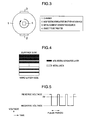
- Fig. 2 illustrates the case where the molybdenum disulfide sputtering source 2 and the metal element generating source 3 are provided on the same side facing the object to be treated, whereby forming with a continuous composition gradient is possible.
- Fig. 3 illustrates the case where the above 2 and 3 are provided facing each other across the center of the object to be treated, whereby the center of the object to be treated is rotated by a drive system, and thereby alternately irradiated from the above 2 and 3.
- a lubricating layer formed in the manner illustrated in Fig. 3 does not have a continuous composition gradient, but can rather be thought of as a super-multilayered coating consisting of molybdenum disulfide layers and metal element layers, having a step-wise structure such as that illustrated in Fig. 4 in which the molybdenum disulfide layers and metal element layers are varied in their thickness as the laminated layers are repeated.
- the interval between laminate layers is fine, it is difficult to detect that this is a stepped laminate layer even with GDS, so that as illustrated in Fig. 1, the composition is viewed as continuously varying. Nevertheless, even such a lubricating layer achieves the layer adhesion and sliding properties, and thereby satisfies the present invention.
- the lubricating layer formed by sputtering is preferably deposited at 380°C or less. If the temperature is greater than 380°C there is a risk even in vacuum deposition that an oxidation reaction with the molybdenum disulfide will occur, whereby layer adhesion would deteriorate. No greater than 350°C is further preferable. While there are no particular limits on the how low the temperature can be, if the deposition temperature is too low oxygen is more likely to remain in the layer, so that 200°C or more is preferable. The range between 250°C and 330°C is more preferable.
- Molybdenum disulfide has a higher electric resistance than metal, so that sputtering is employed in its layer fabrication.
- localized emission phenomenon arcing
- the method should periodically vary the direct voltage applied to the molybdenum disulfide sputtering source, as illustrated in Fig. 5. If performed in such a manner, arcing can be suppressed because immediately after a negative voltage is applied, the reverse voltage (positive voltage) is instantaneously applied.
- the time period for reverse voltage is preferably extremely short.
- a preferable pulse shape has a reverse voltage applied time of from 5 ⁇ s to 20 ⁇ s, and the period is from 30 ⁇ s to 100 ⁇ s. Meanwhile, the reverse voltage value can be about that which can avoid arcing. If the voltage is too high, no further improvement in the effects can be expected, and yet the load placed on the power source becomes greater. For this reason, the value of the reverse voltage from the pulse is preferably between 0% and 30% of the absolute value of the negative voltage.
- Sputtering includes methods such as high-frequency sputtering, magnetron sputtering and ion beam sputtering.
- magnetron sputtering is widely used, although in the deposition of the lubricating layer according to the present invention it is preferable to use an unbalanced magnetron sputtering method where the magnetic field has an unbalanced configuration. If an unbalanced magnetron sputtering method is used, the surface of the object to be treated is cleaned and activated from the effects of ion irradiation on the object, which is characteristic of unbalanced magnetron sputtering, thereby improving the lubricating layer adhesion.
- Ion plating includes methods such as arc discharge, hollow cathode discharge and high-frequency excitation, by means of ionizing the target substance. All of these methods subject the target which will become the layer raw material to high energy, to thereby cause ionization of the target substance. From the perspective of the resulting impurity removal in the chamber, each of these methods achieves a sufficient effect. Among these methods, arc discharge, which has a high ionization rate, has the greatest effect, and is therefore preferable as the means for forming the layer according to the present invention.
- High-speed tool steel SKH51 (cylindrical test piece: 8 mm diameter ⁇ 100 mm length; plate shaped test piece: 3 mm thickness ⁇ 10 mm width ⁇ 30 mm length), which was modified through quenching and tempering to a hardness of 63 HRC, was used for the objects to be treated.
- the objects were mirror polished, and then well washed. Taking the procedure described below as a basis, the multi-layer coating shown in Table 1 were formed. The thickness of the formed multi-layer coating was measured from observation of the cross-section of the plate shaped test piece using an optical microscope or a scanning electron microscope (SEM).
- Analysis of the oxygen concentration in the coating thickness direction was carried out with a GDS (JY 5000RF, manufactured by Horiba Ltd.) using the plate shaped test piece.
- the analyzed region had a diameter of 4 mm, and was measured to a depth of at least the layer thickness of the lubricating layer.
- a composite PVD apparatus which had an arc discharge type ion plating source and two unbalanced magnetron sputtering sources was employed. These two sputtering sources were mounted with respectively a molybdenum disulfide target and a metal target. As illustrated in Fig. 3, these targets were provided so as to opposingly sandwich the object to be treated which was rotating around the chamber center at (0.1 ⁇ ) rad/s. A heater was also provided on the chamber wall face of the apparatus, thereby enabling temperature control of the object to be treated.
- the continuous coating process using the composite PVD apparatus was conducted by, except for a part that will be explained below, first heating the object to be treated in a high vacuum, then subjecting the heated object to plasma cleaning by Ar ions (bias voltage of between -200 V and -300 V), and if necessary again subjecting to plasma cleaning by metal ions (bias voltage of between -300 V and -600 V).
- the chamber interior was filled with a 3.0 Pa atmosphere of nitrogen gas or a mixed gas of nitrogen and methane, and a hard layer consisting of a nitride or a carbonitride was formed (bias voltage of between -50 V and -100 V) by ion plating.
- Deposition temperature was 450°C, and the coating time was adjusted so that the thickness of the hard layer was 2 ⁇ m.
- the numbers written alongside the elements denote the ratio of atoms present (atom number ratio) in the target that was used for the ion plating.
- the sputtering source mounted with the metal target was activated.
- the voltage applied to the sputtering source at this stage was set at the limit at which arcing would not occur.
- the sputtering source mounted with the molybdenum disulfide target was started up from 0 kW.
- the voltage applied at this stage was set to a direct current pulse voltage having a 40 ⁇ s period.
- the reverse voltage applied time was 10 ⁇ s, and the reverse voltage value was set at 10% of the absolute value of the negative voltage.
- the lubricating layer deposition temperature was 300°C.
- the lubricating layer deposition temperature was 400°C.
- the metal element content directly above the hard layer, or that of the top surface, in the lubricating layer was adjusted by varying the output of the metal sputtering source.
- the metal element content was fixed at about 60 atom% in the lubricating layer.
- the hard layer deposition temperature was 350°C.
- a sputtering source was used not only for the lubricating layer, but also for hard layer formation.
- the deposition conditions were a deposition temperature of 450°C, a bias voltage of -100 V and a nitrogen gas pressure of 0.8 Pa.
- the resulting hard layer thickness was 1.0 ⁇ m.
- Nos. 1 to 14 were multi-layer coatings satisfying the present invention, which all achieved a high seize load of 1,960 N or more.
- No. 9 in which Cr was selected as the metal for incorporation into the lubricating layer compared with the Ti of No. 1, had a lower seize load than No. 1, whereby it was learned that mixing Ti into a lubricating layer is effective.
- No. 10 was not formed with a molybdenum disulfide layer on its top surface. Its seize load was lower than that of No. 1, whereby the effectiveness of having a molybdenum disulfide layer was confirmed.
- the metal element content directly above the hard layer in the lubricating layer was not within the preferable range according to the present invention. This meant that adhesion was poor, and that the seize load dropped.
- the metal element content of the top surface of the lubricating layer was not within the preferable range according to the present invention. This meant that the friction coefficient was high, and that the seize load dropped.
- the metal element incorporated in the lubricating layer did not have a graded composition, the metal element (Ti) composition being fixed at 60 atom%. Accordingly, although the lubricating layer had excellent adhesion with the hard layer, seizing occurred even at a light load as the friction coefficient was high. In No. 19, oxygen gas was charged into the atmosphere, whereby the oxygen concentration in the lubricating layer exceeded 25 atom%. This meant that the lubricating layer was brittle, so that peeling took place even at a light load.
- a composite PVD apparatus was not employed as the means for fabricating the layer according to the present invention. Instead, the layer was fabricated using a dedicated apparatus for both the arc discharge type ion plating and the unbalanced magnetron sputtering. As a result, the oxygen concentration in the lubricating layer was not within the values stipulated in the present invention, whereby sufficient lubricating properties could not be achieved.
- the hard layer deposition was carried out at 350°C, whereby the oxygen concentration in the subsequently formed lubricating layer increased, adhesion worsened and the seize load decreased.
- the oxygen impurities in the chamber could not be sufficiently removed, thereby affecting the subsequently formed lubricating layer quality, and a sufficient seize load could not be achieved.
- Example 1 In preparing the layers in Example 1, a number of punches machined from objects were provided. The punches were also coated under the same conditions, respectively, as the objects for Example 1. The material for punches was SKH 51 (hardness 63HRC). Using the coated punches, an actual machine test was carried out for room temperature working of the material to be worked (SUS 304 sheets). The maximum numbers of holes that could be punched were evaluated and the results are shown in Table 3. Table 3 No.
- the present invention can also be applied on a hot die.
- the present invention can also be applied, for example, on a cutting tool or the like.
Abstract
Description
- The present invention relates to a multi-layer coating having excellent adhesion and sliding properties, and production method thereof, which can be applied onto a part surface of tools or similar items, such as a metal die, that are used, for example, in environments ranging from hot to cold.
- The development of solid lubricants has mainly proceeded for intended use in environments wherein lubricating oil could not be easily employed, such as high temperature, extreme low temperature, ultra high pressure, a vacuum and the like. Among such solid lubricants, there are those which can be applied to parts having a complex shape by being deposited as a coating onto the object to be treated by a process such as physical vapor deposition (PVD) or chemical vapor deposition (CVD). Substances such as molybdenum disulfide and diamond-like carbon (DLC) are already being put to practical use.
- Of these, molybdenum disulfide is being applied to many sliding parts to improve seize resistance, due to its superior sliding properties and the fact that it can maintain a low friction coefficient even in an air atmosphere of up to several hundred °C. In particular, by depositing molybdenum disulfide onto a hard layer such as a nitride or a carbonitride which have excellent wear resistance, a multi-layer coating having excellent sliding properties can be produced which has wear resistance and seize resistance at the same time. A method has also been proposed which improves the adhesion and weatherability of a coating by incorporating a metal element into the molybdenum disulfide (
JP-A-2000-001768 - However, molybdenum disulfide has the drawback of being an extremely soft substance, wich when formed into a coating does not always possess sufficient adhesion with the object to be treated. For this reason, if a molybdenum disulfide coating is applied as is onto a sliding part, there is the serious problem that the coating is susceptible at an initial stage of use to peeling and thereby lost without exhibiting sufficient performance. In addition, molybdenum disulfide also has the drawback that it is highly hygroscopic, which causes lubricating performance to deteriorate.
- The above-mentioned
JP-A-2000-001768 JP-A-2000-001768 - It is an object of the present invention to provide a multi-layer coating having excellent adhesion and sliding properties, and production method thereof, by improving on conventional molybdenum disulfide lubricating layers.
- As a result of detailed experimentation and investigation relating to molybdenum disulfide layer carried out by the present inventors, the present inventors realized that if, for example, a nitride, carbonitride or other such compound to serve as a hard layer is formed under the molybdenum disulfide layer, which is a sulfide, sufficient adhesion cannot be achieved because the material properties (constituent elements, interatomic bonds, crystal structure etc.) of these layers are substantially different. Further investigation based on this perspective showed that in order to increase the adhesion of a molybdenum disulfide layer, it is preferable to increase the ratio of the metal element in the layer. This investigation also showed that adhesion and sliding properties can both be sufficiently attained in the same layer by gradiently varying the ratio of the metal element in the layer.
- Moreover, the present inventors showed that the factors influencing the sliding properties of a coating do not only relate to humidity, which had been pointed out in the past, and that oxygen impurities in the layer also have a large influence, thereby arriving at their proposal for an optimal production method for resolving the problems.
- That is, the present invention is a multi-layer coating having excellent adhesion and sliding properties, which comprises a lubricating layer consisting of a metal element and molybdenum disulfide on a hard layer whose main component is a nitride and/or carbonitride comprising one or more elements selected from the group consisting of Ti, V, Zr, Cr, Nb, Si, Al and B, wherein the composition of the lubricating layer is a gradient in which a ratio of the metal element decreases, and a ratio of the molybdenum disulfide increases, going towards the surface from the hard layer side, and wherein a maximum oxygen concentration of the lubricating layer is no greater than 25 atom%. In such a multi-layer coating, the metal element constituting the lubricating layer is preferably Ti. In addition, a 0.01 µm or more thick molybdenum disulfide layer is preferably formed on the top surface of the multi-layer coating.
- The present invention further provides a method for producing a multi-layer coating having excellent adhesion and sliding properties, wherein in forming the multi-layer coating, an ion plating source is used for forming the hard layer, a coating source is used for forming the lubricating layer, and at least the molybdenum disulfide contained therein is deposited using a sputtering source, the ion plating source and the coating source being provided in the same chamber, wherein an object held in the chamber, which is to have the multi-layer coating formed thereon is provided with the hard layer formed at a temperature of 380°C or more and subsequently the lubricating layer formed while the object is held in the chamber. The temperature of the object to be treated when forming the lubricating layer is preferably no greater than 380°C. The ion plating source is preferably an arc discharge type. In addition, the sputtering source for depositing the molybdenum disulfide preferable either applies a direct current pulse voltage, or is an unbalanced magnetron sputtering source.
- By capitalizing on conventional molybdenum disulfide lubricant action, the present invention enables a multi-layer coating having even more excellent adhesion and sliding properties, and production method thereof, to be provided.
-
- Fig. 1 is a view analyzing one example of a multi-layer coating according to the present invention in a coating thickness direction by glow discharge emission spectral analysis (GDS);
- Fig. 2 is a schematic view illustrating one example of an apparatus for forming the lubricating layer of a multi-layer coating according to the present invention;
- Fig. 3 is a schematic view illustrating another example of an apparatus for forming the lubricating layer of a multi-layer coating according to the present invention;
- Fig. 4 is a cross-sectional schematic view illustrating one example of the structure of the lubricating layer of a multi-layer coating according to the present invention; and
- Fig. 5 is an applied voltage pattern for when the molybdenum disulfide contained in a lubricating layer of a multi-layer coating according to the present invention was sputtered.
- One characteristic of the present invention lies in that the factors for insufficient adhesion in a conventional lubricating coating which utilizes a sulfide are clarified. Specifically, when forming a hard layer of carbonitride or the like as an under layer, the adhesion insufficiency of a molybdenum disulfide layer formed thereabove can be resolved through the reexamination and control of the coating structure across both the layers.
- Another characteristic of the present invention lies in the clarification of the factors behind deterioration in sliding properties that were a problem for conventional lubricating coating which utilized a sulfide. Specifically, in addition to the above-described control of the coating structure, by reexamining the constituents contained in the additionally formed molybdenum disulfide layer (lubricating layer), the inadequacy in sliding properties (seize resistance) can also be resolved.
- The present invention is directed to a multi-layer coating that has excellent sliding properties. These properties are realized by coating a substance, which has even better seize resistance and which exhibits a low friction coefficient, so that it adheres well onto a hard layer which is wear resistant. At this stage it is important that the hard layer which will serve as the underlayer has a nitride and/or carbonitride as a main component that is a high-hardness substance having a Vickers hardness of 1,000 HV or more for handling wear resistance. Representative examples of such substances that are often industrially employed include nitrides and carbonitrides comprising one or more elements selected from the group consisting of Ti, V, Zr, Cr, Nb, Si, Al and B.
- Here, the term "main component" means that compounds other than the nitride and/or carbonitride are not excessively present in the hard layer. For example, if oxides or other such compounds are excessively present, the wear resistance which is so important for the hard layer properties according to the present invention deteriorates. Thus, this term is used to mean that the other compounds should be present in such a small amount that does not adversely affect the hard coating. This amount may be such that peaks other than the main component nitride or carbonitride cannot be confirmed by analysis such as X-ray diffraction, for example. However, there are no barriers to incorporating into the hard coating elements other than the Ti and other elements listed above, as long as the incorporated amount is within the range in which the above-described excessive amount of the compounds is not formed. Examples of such elements include O, Hf, Ta, Y and the like.
- In terms of low friction properties and thermal stability, molybdenum disulfide is the most suitable for the lubricating layer formed on the hard layer. However, as stated above, molybdenum disulfide is a soft substance, and when made into a layer has the problem that adhesion is poor. Therefore, to improve the adhesion of molybdenum disulfide it is effective to increase the hardness of molybdenum disulfide. One such technique is to incorporate a metal element into the molybdenum disulfide.
- However, if a metal element is incorporated into molybdenum disulfide, the layer friction properties are worse than those for pure molybdenum disulfide. Thus, as a method to maintain excellent friction properties while exhibiting high adhesion, it is effective to form the layer so as to manifest a gradient composition, wherein the composition of the lubricating layer has a ratio of molybdenum disulfide which increases and a ratio of metal element which decreases going from the hard layer side towards the surface. The term "gradient composition" as used here is defined as the "continuous (or as described below, step-wise) increase or decrease of the chemical composition in a thickness direction". A gradient structure of such a composition can be identified by, for example, glow discharge emission spectral analysis (GDS). GDS not only is highly accurate, but has a fast analysis speed, which make it a suitable technique for coating analysis of a thickness of about a few µm. An example of the analyzed results is shown in Fig. 1.
- Before explaining the gradient composition of the above-described lubricating layer, the entire multi-layer coating according to the present invention will be explained. In GDS, the analyzed object area is approximately a few mm2, which is too broad for the coating thickness of the present invention. Thus, as can be seen in Fig. 1, the layer boundaries do not clearly appear. However, as a consequence, there are no problems in defining the boundary (point A) between the hard layer and the lubricating layer as "the layer thickness site at which the amount of metal (Ti in Fig. 1) constituting the lubricating layer exhibits a peak". The effects of the present invention at such point are sufficiently attained, and are reproducible.
- According to the above definition, the region to the right of point A is the hard layer. As a result, it can be considered that the metal (Ti in Fig. 1) increasing from 0 atom% is present on the surface side of such region, although this is not related to the gist of the present invention. The composition of the hard layer can be evaluated at any depth which lack the above-described metal. The hard layer in the case of Fig. 1 consists of CrN.
- Further, in Fig. 1, the top surface layer comprising the molybdenum disulfide monolayer, which will be described later, has an interface with the lubricating layer, which may be defined as the "depth where the metal element of the lubricating layer disappears" (point B).
- The lubricating layer will now be explained. In Fig. 1 it can be seen that the contained metal Ti content continuously decreases going from point A, which is the lubricating layer start point, towards the surface, while the S content which makes up the molybdenum disulfide continuously increases, thereby achieving the gradient composition according to the present invention. The gradient composition according to the present invention can preferably be quantitatively defined by the metal content curve for which a clear content profile can be easily obtained. That is, with the horizontal axis representing distance from the surface (units: µm) and the vertical axis representing content (units: atom%), a preferable state is where the gradient between two points separated by a distance of 0.2 µm at any section of the metal content curve in the lubricating layer region (between points A and B) is never less than 20, and, similarly, the gradient between two points separated by a distance of 0.05 µm is never greater than 350. It can be seen that in Fig. 1 the decreasing profile of the Ti in the lubricating layer satisfies these defined values.
- Another essential characteristic for the multi-layer coating according to the present invention is the stipulation of the oxygen concentration in the lubricating layer. This is stipulated because the frictional properties of molybdenum disulfide are largely dependent on the contained oxygen concentration, and not just on the contained moisture. If the oxygen concentration is large, the inherent excellent seize resistance is not sufficiently exhibited. In order for the layer according to the present invention to express sufficient sliding properties, the oxygen concentration detected in the layer thickness direction of the lubricating layer must not exceed a maximum of 25 atom%. Preferably, the concentration does not exceed 20 atom%, and more preferably does not exceed 18 atom%. If the oxygen concentration does exceed 25 atom%, the lubricating layer becomes brittle, whereby peeling can easily occur. The oxygen concentration can be determined by GDS analysis. In Fig. 1 the maximum oxygen concentration is 18 atom% (point C).
- In the present invention, there are no particular stipulations on the metal element content in the lubricating layer. However, since the greater the metal element content directly above the hard layer is, the better layer adhesion is, the metal element content at the interface between the hard layer and the lubricating layer preferably has at least 60 atom%. More preferable is 70 atom% or more (including essentially 100 atom%). In Fig. 1, a Ti amount of 80 atom% can be read (point A). On the other hand, at the surface of the lubricating layer, since the lower the metal element content is, the more easily the excellent lubricating properties of molybdenum disulfide are expressed, the metal element content at the surface is preferably no greater than 10 atom%, and more preferably no greater than 5 atom%. It can be noted that, further above that layer, the metal element Ti was not found in the below-described molybdenum disulfide monolayer forming the multi-layer coating illustrated in Fig. 1.
- While Ti was used as an example when explaining the metal element species which along with molybdenum disulfide forms the lubricating layer, this does not particularly limit the elemental species as regards the effect for securing adhesion with the hard layer of the underlayer. It has been confirmed that when one or more of Ti, V, Zr and Cr are selected, good layer adhesion and sufficient sliding properties can be attained. Of these, it has been confirmed that Ti can achieve the most stable adhesion and sliding properties.
- The above-described metal element, which along with molybdenum disulfide constitutes the lubricating layer, is added for the purpose of improving layer adhesion. From the perspective of the inherent lubricating properties, it would be preferable if the metal element was not present. Although a pure molybdenum disulfide layer is susceptible to abrasion from sliding, such a pure layer exhibits an effect of adapting the parts together at the initial stage of sliding. For this purpose the molybdenum disulfide layer at the top surface is preferably present in a thickness of 0.01 µm or more. Although there are no upper limits stipulated for the thickness, because there is the risk that layer adhesion will deteriorate if formed with a more than necessary thickness, an upper limit can be set at about 0.2 µm.
- Next, points regarding a preferable method stipulated by the present invention for the production of the above-described multi-layer coating will be described.
- The multi-layer coating according to the present invention is constituted from layers having differing natures, wherein a hard layer handles wear resistance and a lubricating layer handles seize resistance. Therefore, although the use of different methods could be thought of for the formation of the respective layers, the present invention generally contemplates PVD.
- Representative PVD methods include ion plating and sputtering. An ion plating method comprises a step whose major purpose is the vaporization and ionization of a target substance, which is the ion plating source, during the deposition process. Sputtering, on the other hand, comprises a step whose major purpose is to sputter the target substance in the sputtering source by irradiation of ions or the like during the deposition process. Both of these methods possess their own characteristics, although it is easier in ion plating to form various hard layers having good adhesion by selecting the target substance and atmospheric gas. On the other hand, in sputtering a molybdenum disulfide layer or similar can be easily formed with a high degree of freedom in substance selection.
- Usually these types of PVD apparatus are provided with chambers that are separate from each other, so that when trying to form a multi-layer coating as in the present invention, two batch treatments are necessary. This means that after the hard layer has been formed, the object in process is brought out once into the air atmosphere, which may contaminate its surface by oxidation, and adversely affect adhesion of the lubricating layer formed thereafter. However, for a composite PVD apparatus in which the ion plating source and the sputtering source are incorporated with each other to form the same chamber, a lubricating layer can be formed by first forming the hard layer according to the present invention by ion plating, and then, without taking the object to be treated out of the apparatus, by subsequently activating the sputtering source with the object to be treated kept in the chamber as is, whereby a multi-layer coating can be formed by just one batch treatment.
- Using the composite PVD apparatus according to the present invention means that the process is straightforward and also dramatically increases productivity. However, the main advantage of such an apparatus lies in the following two points. The first advantage is that, as described above, because the object to be treated is not brought out into the air after the hard layer has been formed by ion plating, the surface (i.e. lubricating layer surface) is not subject to oxidation contamination, and can thus be kept clean.
- The second advantage lies in the improved degree of cleanliness of the lubricating layer itself. In the layers according to the present invention it is necessary for the contained oxygen concentration to be no greater than 25 atom% in order for the lubricating layer to exhibit good adhesion. However, if a layer contains a large amount of molybdenum disulfide, it is difficult to attain the above-described oxygen concentration level if a sputtering dedicated apparatus is used only for the purpose of forming the present layer. That is, because molybdenum disulfide is itself extremely susceptible to oxidation and is highly hygroscopic, the chamber interior is contaminated when opened up to the air as a result of molybdenum disulfide which has adhered to the chamber during repeated operation, which will impact on the degree of cleanliness of the subsequent lubricating layers.
- Therefore, for a composite PVD apparatus having the ion plating source and the sputtering source in the same chamber, even should the chamber interior be contaminated by molybdenum disulfide deposition from a prior batch, the chamber interior turns into an active atmosphere at the next batch from the activation of the ion plating source, thereby promoting deoxygenation, whereby the chamber interior is cleaned. Thus, such an apparatus exhibits these effects only because in the formation of a multi-layer coating according to the present invention a hard layer forming step by ion plating must be performed during the lubricating layer forming process.
- In addition to this, if the above-described composite PVD apparatus is utilized in the formation of a multi-layer coating according to the present invention, prior to the formation of the lubricating layer the chamber interior surface is coated with the hard layer, whereby the contamination by molybdenum disulfide accumulated in the prior batch is removed additionally. Because of this action, the use of a composite PVD apparatus is extremely effective in lowering the oxygen concentration in the lubricating layer constituting the multi-layer coating according to the present invention, and is therefore an essential requirement.
- To sufficiently reduce the oxygen concentration of the lubricating layer, in addition to using a composite PVD apparatus, it is necessary to conduct the hard layer deposition at no less than 380°C. Doing so further promotes degassing of the chamber interior, whereby the 25 atom% or less oxygen level in the lubricating layer that is necessary for a sliding part can be achieved. Preferably the temperature is no less than 400°C. While there are no particular limits on the how high the temperature can be, if the deposition temperature is too high the residual compression stress in the hard layer decreases, whereby the required wear resistance necessary as a hard layer deteriorates. Therefore, deposition is preferably carried out in a range of 550°C or less, and the range between 420°C and 500°C is more preferable.
- The multi-layer coating according to the present invention is characterized in gradiently varying the composition of the molybdenum disulfide and the metal element in the lubricating layer. However, to form this layer the generating sources for the molybdenum disulfide and metal element coating are separate, which requires the generating source outputs to each be continuously varied during the lubricating layer formation. Although the molybdenum disulfide deposition must be carried out by a sputtering source, the metal element generating source can be either an ion plating source or a sputtering source. However, from the perspective of easily varying the continuous output, the metal element generating source is preferably also a sputtering source.
- The positional relationship between the molybdenum disulfide sputtering source and the metal element generating source, which are in the same chamber, can be thought of as what is illustrated in Figs. 2 and 3. Fig. 2 illustrates the case where the molybdenum
disulfide sputtering source 2 and the metalelement generating source 3 are provided on the same side facing the object to be treated, whereby forming with a continuous composition gradient is possible. Fig. 3 illustrates the case where the above 2 and 3 are provided facing each other across the center of the object to be treated, whereby the center of the object to be treated is rotated by a drive system, and thereby alternately irradiated from the above 2 and 3. - Strictly speaking, a lubricating layer formed in the manner illustrated in Fig. 3 does not have a continuous composition gradient, but can rather be thought of as a super-multilayered coating consisting of molybdenum disulfide layers and metal element layers, having a step-wise structure such as that illustrated in Fig. 4 in which the molybdenum disulfide layers and metal element layers are varied in their thickness as the laminated layers are repeated. However, because the interval between laminate layers is fine, it is difficult to detect that this is a stepped laminate layer even with GDS, so that as illustrated in Fig. 1, the composition is viewed as continuously varying. Nevertheless, even such a lubricating layer achieves the layer adhesion and sliding properties, and thereby satisfies the present invention.
- The lubricating layer formed by sputtering is preferably deposited at 380°C or less. If the temperature is greater than 380°C there is a risk even in vacuum deposition that an oxidation reaction with the molybdenum disulfide will occur, whereby layer adhesion would deteriorate. No greater than 350°C is further preferable. While there are no particular limits on the how low the temperature can be, if the deposition temperature is too low oxygen is more likely to remain in the layer, so that 200°C or more is preferable. The range between 250°C and 330°C is more preferable.
- Molybdenum disulfide has a higher electric resistance than metal, so that sputtering is employed in its layer fabrication. However, localized emission phenomenon (arcing) tends to occur on the target, whereby the problem exists that a uniform layer is hard to obtain. To avoid such arcing it is effective to suppress the applied power to a low level, although this in turn slows the deposition rate, which is industrially disadvantageous. Therefore, to not substantially lower the deposition rate and to avoid arcing, the method should periodically vary the direct voltage applied to the molybdenum disulfide sputtering source, as illustrated in Fig. 5. If performed in such a manner, arcing can be suppressed because immediately after a negative voltage is applied, the reverse voltage (positive voltage) is instantaneously applied.
- However, since deposition of the layer substance does not occur while the reverse voltage is applied, the time period for reverse voltage is preferably extremely short. A preferable pulse shape has a reverse voltage applied time of from 5 µs to 20 µs, and the period is from 30 µs to 100 µs. Meanwhile, the reverse voltage value can be about that which can avoid arcing. If the voltage is too high, no further improvement in the effects can be expected, and yet the load placed on the power source becomes greater. For this reason, the value of the reverse voltage from the pulse is preferably between 0% and 30% of the absolute value of the negative voltage.
- Sputtering includes methods such as high-frequency sputtering, magnetron sputtering and ion beam sputtering. Of these, magnetron sputtering is widely used, although in the deposition of the lubricating layer according to the present invention it is preferable to use an unbalanced magnetron sputtering method where the magnetic field has an unbalanced configuration. If an unbalanced magnetron sputtering method is used, the surface of the object to be treated is cleaned and activated from the effects of ion irradiation on the object, which is characteristic of unbalanced magnetron sputtering, thereby improving the lubricating layer adhesion.
- Ion plating includes methods such as arc discharge, hollow cathode discharge and high-frequency excitation, by means of ionizing the target substance. All of these methods subject the target which will become the layer raw material to high energy, to thereby cause ionization of the target substance. From the perspective of the resulting impurity removal in the chamber, each of these methods achieves a sufficient effect. Among these methods, arc discharge, which has a high ionization rate, has the greatest effect, and is therefore preferable as the means for forming the layer according to the present invention.
- High-speed tool steel SKH51 (cylindrical test piece: 8 mm diameter × 100 mm length; plate shaped test piece: 3 mm thickness × 10 mm width × 30 mm length), which was modified through quenching and tempering to a hardness of 63 HRC, was used for the objects to be treated. The objects were mirror polished, and then well washed. Taking the procedure described below as a basis, the multi-layer coating shown in Table 1 were formed. The thickness of the formed multi-layer coating was measured from observation of the cross-section of the plate shaped test piece using an optical microscope or a scanning electron microscope (SEM). Analysis of the oxygen concentration in the coating thickness direction was carried out with a GDS (JY 5000RF, manufactured by Horiba Ltd.) using the plate shaped test piece. The analyzed region had a diameter of 4 mm, and was measured to a depth of at least the layer thickness of the lubricating layer.


- Except for No. 20, for the coating depositions in Table 1 a composite PVD apparatus which had an arc discharge type ion plating source and two unbalanced magnetron sputtering sources was employed. These two sputtering sources were mounted with respectively a molybdenum disulfide target and a metal target. As illustrated in Fig. 3, these targets were provided so as to opposingly sandwich the object to be treated which was rotating around the chamber center at (0.1π) rad/s. A heater was also provided on the chamber wall face of the apparatus, thereby enabling temperature control of the object to be treated.
- The continuous coating process using the composite PVD apparatus was conducted by, except for a part that will be explained below, first heating the object to be treated in a high vacuum, then subjecting the heated object to plasma cleaning by Ar ions (bias voltage of between -200 V and -300 V), and if necessary again subjecting to plasma cleaning by metal ions (bias voltage of between -300 V and -600 V). The chamber interior was filled with a 3.0 Pa atmosphere of nitrogen gas or a mixed gas of nitrogen and methane, and a hard layer consisting of a nitride or a carbonitride was formed (bias voltage of between -50 V and -100 V) by ion plating. Deposition temperature was 450°C, and the coating time was adjusted so that the thickness of the hard layer was 2 µm. Of the hard layers shown in Table 1, the numbers written alongside the elements denote the ratio of atoms present (atom number ratio) in the target that was used for the ion plating.
- Once the ion plating had finished, and while the object to be treated was still held in the chamber, plasma cleaning was again carried out with Ar ions, after which the sputtering source mounted with the metal target was activated. The voltage applied to the sputtering source at this stage was set at the limit at which arcing would not occur. Next, the sputtering source mounted with the molybdenum disulfide target was started up from 0 kW. The voltage applied at this stage was set to a direct current pulse voltage having a 40 µs period. The reverse voltage applied time was 10 µs, and the reverse voltage value was set at 10% of the absolute value of the negative voltage. Then, while slowly increasing the power applied to the molybdenum disulfide sputtering source, the power applied to the metal sputtering source was slowly decreased. Finally, deposition from only the molybdenum disulfide sputtering source was carried out as necessary for a few minutes, whereby coating was completed. The lubricating layer deposition temperature was 300°C.
- The coating samples that had different steps from those described above will be now briefly explained below.
- In No. 11, a non-pulsed, ordinary direct voltage was applied to the molybdenum disulfide sputtering source.
- In No. 12, the lubricating layer deposition temperature was 400°C.
- In Nos. 13 and 14, the metal element content directly above the hard layer, or that of the top surface, in the lubricating layer was adjusted by varying the output of the metal sputtering source.
- In No. 15, a hard layer was not formed.
- In No. 16, a molybdenum disulfide sputtering source was not used.
- In No. 17, a metal sputtering source was not used during lubricating layer formation.
- In No. 18, the metal element content was fixed at about 60 atom% in the lubricating layer.
- In No. 19, a minute amount of oxygen gas was charged into the atmosphere during lubricating layer formation.
- In No. 20, a composite PVD apparatus was not used at all. An arc discharge type ion plating apparatus and an unbalanced magnetron sputtering apparatus which had separate chambers were employed.
- In No. 21, the hard layer deposition temperature was 350°C.
- In No. 22, a sputtering source was used not only for the lubricating layer, but also for hard layer formation. The deposition conditions were a deposition temperature of 450°C, a bias voltage of -100 V and a nitrogen gas pressure of 0.8 Pa. The resulting hard layer thickness was 1.0 µm.
- Evaluation of the seize resistance of the deposited coatings was conducted by a reciprocating frictional wear test using the cylindrical test piece. No external lubricating agent was supplied during the test, in which the test piece was pressed at a right angle with a fixed load against an identically shaped reciprocating piece S35C (150 to 160 HV). These pieces were slid in a reciprocating manner at a friction velocity of 0.83 m/s. The pressed load was increased by 98 N for every 13 m that the pieces were made to slide. Although this test was intended to check the load when seizing took place in the test pieces, factors for seizing occurrence include cases where the test piece surface strength is unable to withstand the load being pressed against it, thereby leading to breakage, and cases where the test piece contacting portion undergoes local melting due to the heat of friction generated by sliding. Either of these factors are detected as the occurrence of seizing. The maximum load for the present test machine was 2,940 N. The test results are shown in Table 2.
Table 2 No. Seize Occurrence Load (N) Remarks 1 2940 present invention 2 2550 " 3 2160 " 4 2750 " 5 2650 " 6 2350 " 7 more than 2940 " 8 2350 " 9 2450 " 10 2350 " 11 2060 " 12 2050 " 13 2000 " 14 2000 " 15 880 comparative example 16 780 " 17 1570 " 18 1770 " 19 1270 " 20 1270 " 21 1000 " 22 1000 " - Nos. 1 to 14 were multi-layer coatings satisfying the present invention, which all achieved a high seize load of 1,960 N or more. Among these, No. 9, in which Cr was selected as the metal for incorporation into the lubricating layer compared with the Ti of No. 1, had a lower seize load than No. 1, whereby it was learned that mixing Ti into a lubricating layer is effective. Unlike No. 1, No. 10 was not formed with a molybdenum disulfide layer on its top surface. Its seize load was lower than that of No. 1, whereby the effectiveness of having a molybdenum disulfide layer was confirmed.
- In No. 11, a non-pulsed ordinary direct voltage was applied to the molybdenum disulfide target, which caused the thickness of the lubricating layer to become thinner and thus have a lower seize load than that of the other coatings according to the present invention. In No. 12, lubricating layer deposition was carried out at 400°C. Since even in a vacuum a minute amount of molybdenum disulfide is oxidized at such a high temperature, the oxygen concentration in the lubricating layer rose, and lubricating layer adhesion fell. However, in No. 12, which had an oxygen concentration of no more than 25 atom%, a seize load of 1,960 N, which is enough for use as a sliding part, was achieved.
- In No. 13, the metal element content directly above the hard layer in the lubricating layer was not within the preferable range according to the present invention. This meant that adhesion was poor, and that the seize load dropped. In No. 14, the metal element content of the top surface of the lubricating layer was not within the preferable range according to the present invention. This meant that the friction coefficient was high, and that the seize load dropped.
- Meanwhile, in Nos. 15 to 22 the multi-layer coating according to the present invention was not achieved. In No. 15, a hard layer which would act as the underlayer was not formed in the multi-layer coating, so that seizing quickly occurred. If there is no hard layer present, early seizing easily occurs even if the lubricating layer is present, since the hard layer plays a major role in wear resistance.
- In No. 16, a lubricating layer was not formed in the multi-layer coating. In this case, since the respective test pieces stuck together from the heat of friction generated by the sliding parts, even if a hard layer had been coated, seizing would occur at a low load. In No. 17, a metal element was not incorporated in the lubricating layer, whereby the adhesion with the hard layer serving as the underlayer was insufficient, and seizing occurred.
- In No. 18, the metal element incorporated in the lubricating layer did not have a graded composition, the metal element (Ti) composition being fixed at 60 atom%. Accordingly, although the lubricating layer had excellent adhesion with the hard layer, seizing occurred even at a light load as the friction coefficient was high. In No. 19, oxygen gas was charged into the atmosphere, whereby the oxygen concentration in the lubricating layer exceeded 25 atom%. This meant that the lubricating layer was brittle, so that peeling took place even at a light load.
- In No. 20, a composite PVD apparatus was not employed as the means for fabricating the layer according to the present invention. Instead, the layer was fabricated using a dedicated apparatus for both the arc discharge type ion plating and the unbalanced magnetron sputtering. As a result, the oxygen concentration in the lubricating layer was not within the values stipulated in the present invention, whereby sufficient lubricating properties could not be achieved.
- In No. 21, the hard layer deposition was carried out at 350°C, whereby the oxygen concentration in the subsequently formed lubricating layer increased, adhesion worsened and the seize load decreased. In No. 22, because a sputtering source was used to form the hard layer, the oxygen impurities in the chamber could not be sufficiently removed, thereby affecting the subsequently formed lubricating layer quality, and a sufficient seize load could not be achieved.
- In preparing the layers in Example 1, a number of punches machined from objects were provided. The punches were also coated under the same conditions, respectively, as the objects for Example 1. The material for punches was SKH 51 (hardness 63HRC). Using the coated punches, an actual machine test was carried out for room temperature working of the material to be worked (SUS 304 sheets). The maximum numbers of holes that could be punched were evaluated and the results are shown in Table 3.
Table 3 No. number of punching Remarks 1 13,600 present invention 2 12,200 " 3 11,500 " 4 14,500 " 5 13,300 " 6 13,400 " 7 15,800 " 8 12,000 " 9 12,100 " 10 11,000 " 11 10,900 " 12 10,900 " 13 10,000 " 14 10,300 " 15 3,600 comparative example 16 5,000 " 17 8,200 " 18 8,700 " 19 6,900 " 20 6,300 " 21 7,100 " 22 5,500 " - From Table 3, it can be seen that in the example according to the present invention the Nos. 1 to 14 punches were all able to punch a number sufficient for practical use of 10, 000 holes or more, thus generally reflecting the results of the reciprocating frictional wear test of Example 1.
- In addition to use in environments ranging from hot to cold as a metal die or similar utilized in a punch employed in punching, or in pressing or forging, the present invention can also be applied on a hot die. Moreover, taking into consideration the fact that its multi-layer coating has excellent sliding properties, the present invention can also be applied, for example, on a cutting tool or the like.
Claims (8)
- A multi-layer coating having excellent adhesion and sliding properties, which comprises a hard layer having a main component of a nitride and/or carbonitride of one or more elements selected from the group consisting of Ti, V, Zr, Cr, Nb, Si, Al and B and a lubricating layer consisting of a metal element and molybdenum disulfide on the hard layer wherein the lubricating layer has a graded composition in which the metal element has a decreasing content from the hard layer side towards the surface and the molybdenum disulfide has an increasing content, and wherein the lubricating layer has a maximum oxygen concentration of no greater than 25 atom%.
- The multi-layer coating having excellent adhesion and sliding properties according to claim 1, wherein the metal element for forming the lubricating layer is Ti.
- The multi-layer coating having excellent adhesion and sliding properties according to claim 1, wherein a 0.01 µm or more thick molybdenum disulfide layer is formed on the top surface of the multi-layer coating.
- A method for producing the multi-layer coating having excellent adhesion and sliding properties according to any of claims 1-3, wherein in forming the multi-layer coating, an ion plating source is used for forming the hard layer, a coating source is used for forming the lubricating layer, and at least the molybdenum disulfide contained therein is deposited using a sputtering source, the ion plating source and the coating source being provided in the same chamber, wherein an object held in the chamber, which is to have the multi-layer coating formed thereon, is provided with the hard layer formed at a temperature of 380°C or more and subsequently the lubricating layer formed while the object is held in the chamber.
- The method for producing the multi-layer coating having excellent adhesion and sliding properties according to claim 4, wherein the ion plating source is an arc discharge type.
- The method for producing the multi-layer coating having excellent adhesion and sliding properties according to claim 4 or 5, wherein the lubricating layer is formed on the object at no greater than 380°C.
- The method for producing the multi-layer coating having excellent adhesion and sliding properties according to any of claims 4-6, wherein the sputtering source for depositing molybdenum disulfide applies a direct current pulse voltage.
- The method for producing the multi-layer coating having excellent adhesion and sliding properties according to any of claims 4-7, wherein the sputtering source for depositing molybdenum disulfide is an unbalanced magnetron sputtering source.
Applications Claiming Priority (1)
| Application Number | Priority Date | Filing Date | Title |
|---|---|---|---|
| JP2005116098A JP4771202B2 (en) | 2005-04-13 | 2005-04-13 | Composite film having excellent adhesion and sliding properties and method for producing the same |
Publications (2)
| Publication Number | Publication Date |
|---|---|
| EP1712654A1 true EP1712654A1 (en) | 2006-10-18 |
| EP1712654B1 EP1712654B1 (en) | 2009-12-30 |
Family
ID=36463411
Family Applications (1)
| Application Number | Title | Priority Date | Filing Date |
|---|---|---|---|
| EP06006427A Expired - Fee Related EP1712654B1 (en) | 2005-04-13 | 2006-03-28 | Multi-layer coating having excellent adhesion and sliding properties and production method thereof |
Country Status (6)
| Country | Link |
|---|---|
| US (1) | US7485372B2 (en) |
| EP (1) | EP1712654B1 (en) |
| JP (1) | JP4771202B2 (en) |
| CN (1) | CN100513167C (en) |
| AT (1) | ATE453734T1 (en) |
| DE (1) | DE602006011386D1 (en) |
Cited By (2)
| Publication number | Priority date | Publication date | Assignee | Title |
|---|---|---|---|---|
| WO2009112238A1 (en) * | 2008-03-13 | 2009-09-17 | Ewald Dörken Ag | Method for adjusting the friction coefficient of a metallic workpiece |
| WO2014056605A1 (en) * | 2012-10-10 | 2014-04-17 | Oerlikon Trading Ag, Trübbach | Coatings for high-temperatures uses with tri-biological stress |
Families Citing this family (26)
| Publication number | Priority date | Publication date | Assignee | Title |
|---|---|---|---|---|
| EP1918421B1 (en) * | 2006-09-27 | 2017-03-15 | Hitachi Metals, Ltd. | Hard-material-coated member excellent in durability |
| JP2010012744A (en) * | 2008-07-07 | 2010-01-21 | Shimano Inc | Synthetic resin complex |
| CN102115867A (en) * | 2009-12-30 | 2011-07-06 | 深圳森丰真空镀膜有限公司 | Method for improving corrosion-resisting, wear-resisting and self-lubricating properties of metal by coating technology |
| CN103339283B (en) * | 2011-02-01 | 2015-09-09 | Osg株式会社 | The stacked tunicle of hard |
| US9101979B2 (en) | 2011-10-31 | 2015-08-11 | California Institute Of Technology | Methods for fabricating gradient alloy articles with multi-functional properties |
| RU2495950C1 (en) * | 2012-06-26 | 2013-10-20 | Федеральное государственное бюджетное образовательное учреждение высшего профессионального образования "Ульяновский государственный технический университет" | Method of producing sandwiched coating for cutting tool |
| RU2495952C1 (en) * | 2012-07-03 | 2013-10-20 | Федеральное государственное бюджетное образовательное учреждение высшего профессионального образования "Ульяновский государственный технический университет" | Method of producing sandwiched coating for cutting tool |
| RU2548863C2 (en) * | 2013-07-19 | 2015-04-20 | Федеральное государственное бюджетное образовательное учреждение высшего профессионального образования "Ульяновский государственный технический университет" | Method of sandwiched coating obtainment for cutting tool |
| RU2545958C2 (en) * | 2013-07-26 | 2015-04-10 | Федеральное государственное бюджетное образовательное учреждение высшего профессионального образования "Ульяновский государственный технический университет" | Method to produce multi-layer coating for cutting tool |
| RU2545972C2 (en) * | 2013-07-26 | 2015-04-10 | Федеральное государственное бюджетное образовательное учреждение высшего профессионального образования "Ульяновский государственный технический университет" | Method to produce multi-layer coating for cutting tool |
| RU2548553C2 (en) * | 2013-08-02 | 2015-04-20 | Федеральное государственное бюджетное образовательное учреждение высшего профессионального образования "Ульяновский государственный технический университет" | Method for obtaining multi-layered coating for cutting tool |
| CN103805949B (en) * | 2014-02-17 | 2016-07-27 | 武汉大学 | Molybdenum bisuphide self-lubricating composite coating and be covered with the piston ring of this composite coating |
| KR101640912B1 (en) * | 2014-07-03 | 2016-07-20 | 현대자동차주식회사 | High temperature low friction coating layer and the method of the same |
| CN105463391B (en) * | 2015-01-09 | 2018-02-06 | 天津职业技术师范大学 | A kind of nanocrystalline ZrB2Superhard coating and preparation method |
| GB201507524D0 (en) * | 2015-05-01 | 2015-06-17 | Teer Coatings Ltd | Improvements to molybdenum containing coatings |
| CN104862648B (en) * | 2015-06-16 | 2017-09-22 | 张平 | A kind of excellent MoS of wear Characteristics2Ti composite membranes and preparation method thereof |
| US20180361447A1 (en) * | 2015-12-07 | 2018-12-20 | Ihi Ionbond Ag | Coated extrusion tool |
| RU2643536C1 (en) * | 2017-04-04 | 2018-02-02 | федеральное государственное бюджетное образовательное учреждение высшего образования "Ульяновский государственный технический университет" | Method of producing wear-resitant coating for cutting tool |
| CN108103454B (en) * | 2017-11-30 | 2019-10-11 | 厦门金鹭特种合金有限公司 | A kind of high smooth coated cutting tool and preparation method thereof |
| CN109267042B (en) * | 2018-10-17 | 2020-07-03 | 中国兵器工业第五九研究所 | Preparation method of wear-resistant self-lubricating coating of steel material |
| CN110735120B (en) * | 2019-10-31 | 2021-08-13 | 江苏科技大学 | NbN/MoSN/MoS2Hard self-lubricating nano-structure composite film and preparation method thereof |
| CN111172498A (en) * | 2020-01-19 | 2020-05-19 | 中国科学院宁波材料技术与工程研究所 | Molybdenum disulfide/tungsten disulfide multilayer tantalum-doped thin film and preparation method and application thereof |
| CN111304616A (en) * | 2020-04-03 | 2020-06-19 | 中国科学院兰州化学物理研究所 | Preparation method of Ti and C doped molybdenum disulfide based nano composite film |
| CN111485212B (en) * | 2020-06-04 | 2022-02-22 | 兰州文理学院 | Preparation method of molybdenum disulfide-carbon multilayer film with sub-10-nanometer bionic structure |
| CN114318270B (en) * | 2022-01-07 | 2023-12-15 | 仪征亚新科双环活塞环有限公司 | Running-in coating for improving friction performance of hard coating on outer circumferential surface of piston ring in running-in period and preparation method thereof |
| CN116497457B (en) * | 2023-05-29 | 2023-09-12 | 中国科学院宁波材料技术与工程研究所 | Superlattice composite coating with low friction and long service life and preparation method and application thereof |
Citations (5)
| Publication number | Priority date | Publication date | Assignee | Title |
|---|---|---|---|---|
| WO1999055930A1 (en) * | 1998-04-27 | 1999-11-04 | European Community | A low friction coating for a cutting tool |
| JP2000001768A (en) | 1998-06-16 | 2000-01-07 | Nippon Coating Center Kk | Composite wear resistant hard coating film having solid lubricity and article with coating film |
| US6423419B1 (en) * | 1995-07-19 | 2002-07-23 | Teer Coatings Limited | Molybdenum-sulphur coatings |
| EP1245699A2 (en) * | 2001-03-30 | 2002-10-02 | Hitachi Metals, Ltd. | Coated tool for warm and/or hot working |
| US6528171B1 (en) * | 1999-03-03 | 2003-03-04 | Widia Gmbh | Tool with a molybdenum sulfide containing coating and method for its production |
Family Cites Families (11)
| Publication number | Priority date | Publication date | Assignee | Title |
|---|---|---|---|---|
| JPS61255998A (en) | 1985-05-10 | 1986-11-13 | Mitsubishi Heavy Ind Ltd | Composite lubricant coating |
| CA2078245A1 (en) * | 1991-09-23 | 1993-03-24 | Roland Dubach | Machining tools |
| EP0558061B1 (en) | 1992-02-27 | 2000-08-09 | Hauzer Industries Bv | Improvements in physical vapour deposition processes |
| JPH07268620A (en) | 1994-03-28 | 1995-10-17 | Nikon Corp | Molydbdenum sulfide lubricating film to be used under light load |
| US5843533A (en) * | 1995-03-23 | 1998-12-01 | Lockheed Martin Energy Systems, Inc. | CVD method of forming self-lubricating composites |
| GB9514773D0 (en) | 1995-07-19 | 1995-09-20 | Teer Coatings Ltd | Methods for improving the sputter deposition of metal-sulphur coatings e.g.molybdenum disulphide(MoS2) coatings |
| EP1161573B1 (en) * | 1999-03-03 | 2002-09-04 | Widia GmbH | Tool with a molybdenum sulphide coating and method for producing the same |
| JP2001140057A (en) * | 1999-11-17 | 2001-05-22 | Toyota Motor Corp | Self-lubricating sliding material |
| JP2002307128A (en) * | 2001-04-10 | 2002-10-22 | Hitachi Metals Ltd | Coating tool for warm and hot working having excellent seizure resistance and wear resistance |
| JP4756434B2 (en) * | 2001-06-14 | 2011-08-24 | 日立金属株式会社 | Film forming device |
| US7147939B2 (en) * | 2003-02-27 | 2006-12-12 | Kennametal Inc. | Coated carbide tap |
-
2005
- 2005-04-13 JP JP2005116098A patent/JP4771202B2/en not_active Expired - Fee Related
-
2006
- 2006-03-15 US US11/375,255 patent/US7485372B2/en not_active Expired - Fee Related
- 2006-03-28 AT AT06006427T patent/ATE453734T1/en active
- 2006-03-28 EP EP06006427A patent/EP1712654B1/en not_active Expired - Fee Related
- 2006-03-28 DE DE602006011386T patent/DE602006011386D1/en active Active
- 2006-04-12 CN CNB2006100753270A patent/CN100513167C/en not_active Expired - Fee Related
Patent Citations (5)
| Publication number | Priority date | Publication date | Assignee | Title |
|---|---|---|---|---|
| US6423419B1 (en) * | 1995-07-19 | 2002-07-23 | Teer Coatings Limited | Molybdenum-sulphur coatings |
| WO1999055930A1 (en) * | 1998-04-27 | 1999-11-04 | European Community | A low friction coating for a cutting tool |
| JP2000001768A (en) | 1998-06-16 | 2000-01-07 | Nippon Coating Center Kk | Composite wear resistant hard coating film having solid lubricity and article with coating film |
| US6528171B1 (en) * | 1999-03-03 | 2003-03-04 | Widia Gmbh | Tool with a molybdenum sulfide containing coating and method for its production |
| EP1245699A2 (en) * | 2001-03-30 | 2002-10-02 | Hitachi Metals, Ltd. | Coated tool for warm and/or hot working |
Non-Patent Citations (3)
| Title |
|---|
| FOX V C ET AL: "The structure of tribologically improved MoS2-metal composite coatings and their industrial applications", SURFACE AND COATINGS TECHNOLOGY ELSEVIER SWITZERLAND, vol. 116-119, September 1999 (1999-09-01), pages 492 - 497, XP002384248, ISSN: 0257-8972 * |
| RIGATO V ET AL: "Properties of sputter-deposited MoS2/metal composite coatings deposited by closed field unbalanced magnetron sputter ion plating", SURFACE AND COATINGS TECHNOLOGY ELSEVIER SWITZERLAND, vol. 131, no. 1-3, 1 September 2000 (2000-09-01), pages 206 - 210, XP002391415, ISSN: 0257-8972 * |
| WANG D -Y ET AL: "Microstructural and tribological characterization of MoS2-Ti composite solid lubricating films", SURFACE AND COATINGS TECHNOLOGY ELSEVIER SWITZERLAND, vol. 120-121, November 1999 (1999-11-01), pages 629 - 635, XP002384249, ISSN: 0257-8972 * |
Cited By (8)
| Publication number | Priority date | Publication date | Assignee | Title |
|---|---|---|---|---|
| WO2009112238A1 (en) * | 2008-03-13 | 2009-09-17 | Ewald Dörken Ag | Method for adjusting the friction coefficient of a metallic workpiece |
| AU2009224948B2 (en) * | 2008-03-13 | 2012-12-20 | Ewald Dorken Ag | Method for adjusting the friction coefficient of a metallic workpiece |
| EA020839B1 (en) * | 2008-03-13 | 2015-02-27 | Эвальд Деркен Аг | Method for adjusting the friction coefficient of a metallic workpiece |
| WO2014056605A1 (en) * | 2012-10-10 | 2014-04-17 | Oerlikon Trading Ag, Trübbach | Coatings for high-temperatures uses with tri-biological stress |
| WO2014075787A1 (en) * | 2012-11-13 | 2014-05-22 | Oerlikon Trading Ag, Trübbach | Coating for high temperature applications with tribological stress |
| CN105026530A (en) * | 2012-11-13 | 2015-11-04 | 欧瑞康表面解决方案股份公司,特吕巴赫 | Coating for high temperature applications with tribological stress |
| US9623468B2 (en) | 2012-11-13 | 2017-04-18 | Oerlikon Surface Solutions Ag, Pfäffikon | Coating for high temperature applications with tribological stress |
| CN105026530B (en) * | 2012-11-13 | 2017-10-03 | 欧瑞康表面解决方案股份公司,普费菲孔 | Coating for the high temperature application with friction stree |
Also Published As
| Publication number | Publication date |
|---|---|
| JP4771202B2 (en) | 2011-09-14 |
| ATE453734T1 (en) | 2010-01-15 |
| US20060234081A1 (en) | 2006-10-19 |
| JP2006291324A (en) | 2006-10-26 |
| CN100513167C (en) | 2009-07-15 |
| EP1712654B1 (en) | 2009-12-30 |
| CN1846990A (en) | 2006-10-18 |
| DE602006011386D1 (en) | 2010-02-11 |
| US7485372B2 (en) | 2009-02-03 |
Similar Documents
| Publication | Publication Date | Title |
|---|---|---|
| EP1712654B1 (en) | Multi-layer coating having excellent adhesion and sliding properties and production method thereof | |
| EP1992713B1 (en) | Hard coating excellent in wear resistance and in oxidation resistance and target for forming the same | |
| CA2483491C (en) | A bone saw blade and method for manufacturing a bone saw blade | |
| EP1245699B1 (en) | Coated tool for warm and/or hot working | |
| EP2138602B1 (en) | Hard coating laminate and method for forming hard coating laminate | |
| EP1736565A1 (en) | Composite coatings for finishing of hardened steels | |
| EP2305405A1 (en) | Coated member | |
| CN110691662B (en) | Coated cutting tool | |
| EP3643805A1 (en) | Sliding member and coating film | |
| CN111511490B (en) | Coated cutting tool | |
| CN113416926A (en) | Nano multilayer structure transition metal nitride coating and preparation method and application thereof | |
| JP2003113463A (en) | COATED MEMBER WITH TiAl ALLOY FILM AND MANUFACTURING METHOD THEREFOR | |
| US20240093344A1 (en) | Hard carbon coatings with improved adhesion strength by means of hipims and method thereof | |
| EP3181729A1 (en) | Hard coating and die | |
| CN113613817B (en) | Coated cutting tool | |
| EP3109341A1 (en) | Hard coating film and method of forming same | |
| US20230390829A1 (en) | Coated cutting tool | |
| KR20230102643A (en) | Cutting tools with hard coating | |
| CN113365768A (en) | Coated cutting tool | |
| JP7240045B2 (en) | AlCr oxidation-resistant wear-resistant coating and its coating | |
| JP7031791B2 (en) | Cover cutting tool | |
| JP5649215B2 (en) | Coated member with excellent wear resistance and sliding properties and method for producing the same | |
| KR100779740B1 (en) | Coating materials for surface covering | |
| KR100889372B1 (en) | Multi-layer hard film having good thermal stability | |
| JP2003094208A (en) | MEMBER CLAD WITH FILM OF TiAl COMPOUND, AND MANUFACTURING METHOD THEREFOR |
Legal Events
| Date | Code | Title | Description |
|---|---|---|---|
| PUAI | Public reference made under article 153(3) epc to a published international application that has entered the european phase |
Free format text: ORIGINAL CODE: 0009012 |
|
| AK | Designated contracting states |
Kind code of ref document: A1 Designated state(s): AT BE BG CH CY CZ DE DK EE ES FI FR GB GR HU IE IS IT LI LT LU LV MC NL PL PT RO SE SI SK TR |
|
| AX | Request for extension of the european patent |
Extension state: AL BA HR MK YU |
|
| 17P | Request for examination filed |
Effective date: 20070412 |
|
| 17Q | First examination report despatched |
Effective date: 20070516 |
|
| AKX | Designation fees paid |
Designated state(s): AT DE GB |
|
| R17C | First examination report despatched (corrected) |
Effective date: 20070518 |
|
| GRAP | Despatch of communication of intention to grant a patent |
Free format text: ORIGINAL CODE: EPIDOSNIGR1 |
|
| GRAS | Grant fee paid |
Free format text: ORIGINAL CODE: EPIDOSNIGR3 |
|
| GRAA | (expected) grant |
Free format text: ORIGINAL CODE: 0009210 |
|
| AK | Designated contracting states |
Kind code of ref document: B1 Designated state(s): AT DE GB |
|
| REG | Reference to a national code |
Ref country code: GB Ref legal event code: FG4D |
|
| REF | Corresponds to: |
Ref document number: 602006011386 Country of ref document: DE Date of ref document: 20100211 Kind code of ref document: P |
|
| PLBE | No opposition filed within time limit |
Free format text: ORIGINAL CODE: 0009261 |
|
| STAA | Information on the status of an ep patent application or granted ep patent |
Free format text: STATUS: NO OPPOSITION FILED WITHIN TIME LIMIT |
|
| 26N | No opposition filed |
Effective date: 20101001 |
|
| PGFP | Annual fee paid to national office [announced via postgrant information from national office to epo] |
Ref country code: DE Payment date: 20190312 Year of fee payment: 14 Ref country code: GB Payment date: 20190327 Year of fee payment: 14 |
|
| PGFP | Annual fee paid to national office [announced via postgrant information from national office to epo] |
Ref country code: AT Payment date: 20190226 Year of fee payment: 14 |
|
| REG | Reference to a national code |
Ref country code: DE Ref legal event code: R119 Ref document number: 602006011386 Country of ref document: DE |
|
| REG | Reference to a national code |
Ref country code: AT Ref legal event code: MM01 Ref document number: 453734 Country of ref document: AT Kind code of ref document: T Effective date: 20200328 |
|
| PG25 | Lapsed in a contracting state [announced via postgrant information from national office to epo] |
Ref country code: DE Free format text: LAPSE BECAUSE OF NON-PAYMENT OF DUE FEES Effective date: 20201001 Ref country code: AT Free format text: LAPSE BECAUSE OF NON-PAYMENT OF DUE FEES Effective date: 20200328 |
|
| GBPC | Gb: european patent ceased through non-payment of renewal fee |
Effective date: 20200328 |
|
| PG25 | Lapsed in a contracting state [announced via postgrant information from national office to epo] |
Ref country code: GB Free format text: LAPSE BECAUSE OF NON-PAYMENT OF DUE FEES Effective date: 20200328 |