EP1712473A1 - Device for feeeding disc shaped objects, in particular tablets, to a sealing apparatus - Google Patents
Device for feeeding disc shaped objects, in particular tablets, to a sealing apparatus Download PDFInfo
- Publication number
- EP1712473A1 EP1712473A1 EP06006884A EP06006884A EP1712473A1 EP 1712473 A1 EP1712473 A1 EP 1712473A1 EP 06006884 A EP06006884 A EP 06006884A EP 06006884 A EP06006884 A EP 06006884A EP 1712473 A1 EP1712473 A1 EP 1712473A1
- Authority
- EP
- European Patent Office
- Prior art keywords
- finger
- sealing
- feeding device
- objects
- conveyor
- Prior art date
- Legal status (The legal status is an assumption and is not a legal conclusion. Google has not performed a legal analysis and makes no representation as to the accuracy of the status listed.)
- Granted
Links
Images


Classifications
-
- B—PERFORMING OPERATIONS; TRANSPORTING
- B65—CONVEYING; PACKING; STORING; HANDLING THIN OR FILAMENTARY MATERIAL
- B65B—MACHINES, APPARATUS OR DEVICES FOR, OR METHODS OF, PACKAGING ARTICLES OR MATERIALS; UNPACKING
- B65B35/00—Supplying, feeding, arranging or orientating articles to be packaged
- B65B35/10—Feeding, e.g. conveying, single articles
- B65B35/20—Feeding, e.g. conveying, single articles by reciprocating or oscillatory pushers
-
- B—PERFORMING OPERATIONS; TRANSPORTING
- B65—CONVEYING; PACKING; STORING; HANDLING THIN OR FILAMENTARY MATERIAL
- B65B—MACHINES, APPARATUS OR DEVICES FOR, OR METHODS OF, PACKAGING ARTICLES OR MATERIALS; UNPACKING
- B65B35/00—Supplying, feeding, arranging or orientating articles to be packaged
- B65B35/10—Feeding, e.g. conveying, single articles
- B65B35/26—Feeding, e.g. conveying, single articles by rotary conveyors
-
- B—PERFORMING OPERATIONS; TRANSPORTING
- B65—CONVEYING; PACKING; STORING; HANDLING THIN OR FILAMENTARY MATERIAL
- B65B—MACHINES, APPARATUS OR DEVICES FOR, OR METHODS OF, PACKAGING ARTICLES OR MATERIALS; UNPACKING
- B65B9/00—Enclosing successive articles, or quantities of material, e.g. liquids or semiliquids, in flat, folded, or tubular webs of flexible sheet material; Subdividing filled flexible tubes to form packages
- B65B9/02—Enclosing successive articles, or quantities of material between opposed webs
- B65B9/04—Enclosing successive articles, or quantities of material between opposed webs one or both webs being formed with pockets for the reception of the articles, or of the quantities of material
- B65B9/045—Enclosing successive articles, or quantities of material between opposed webs one or both webs being formed with pockets for the reception of the articles, or of the quantities of material for single articles, e.g. tablets
Definitions
- the invention relates to a device for feeding flat, disc-shaped objects, such as pharmaceutical tablets and similar technical small parts, in particular tablets, to sealing tools for sealing the objects in packaging film, according to the preamble of patent claim 1.
- the invention is explained below using the example of circular tablets, such as effervescent tablets, with a diameter in the range of about 16 to 30 mm and a thickness in the range of about 3 to 8 mm.
- the tablets are individually sealed by sealing devices into so-called four-edge sealing bags, wherein two heat-sealing foils, for example aluminum-laminated foils, provided as endless strips, are typically sealed together to form the sealed pouches.
- Several such four-edge seal bags can be connected in a strip shape as an endless belt and after its division into differently sized packaging units.
- tablets this is understood as representative of any type of flat, disc-shaped objects or corresponding technical small parts that are packaged in the same way. It is always about the promotion and packaging of the articles in high quantities at high conveyor speeds.
- This vertical feeding of the tablets to the sealing device has several drawbacks: in the free-fall phase, the tablet moves uncontrollably, depending on its mass, so that different falling times and positioning of the tablets between the sealing rolls may occur, leading to different positions of the respective tablet can lead to the formed edge seal bag.
- the behavior of the tablet in the free-fall phase may also be affected by fouling of the tablet supply and a possibly resulting adhesive effect, whereby the tablets are transferred from the tablet supply into free fall at different times. Also, by different entrainment effects between the film and the tablet, for example due to different film qualities, the location of the respective tablet in the bag may be different.
- the tablets are fed to the sealing tools on a substantially horizontally arranged conveying track, wherein a first conveying device in the form of a finger roller positions and pushes the tablets abutting one another in a jam, and wherein a second conveying device engaging in the conveying path takes the form of two said polygonal rollers, the tablets separated from the jam and further advancing and feeding the heat seal rollers.
- a first conveying device in the form of a finger roller positions and pushes the tablets abutting one another in a jam
- a second conveying device engaging in the conveying path takes the form of two said polygonal rollers, the tablets separated from the jam and further advancing and feeding the heat seal rollers.
- the finger roller, the polygonal rollers and the heat sealing rollers are arranged one behind the other such that supply, Positioning, singulation and sealing of the tablets take place in a horizontal plane.
- the invention is therefore based on the object to overcome the above-mentioned disadvantages of the prior art and in particular to improve the positioning of the tablets in the sealing yards of the sealing tools and thus in the individual sealed packages and in particular a safe and accurate, reproducible Positioning the tablets in reach.
- a feeding device for feeding the flat, disc-shaped objects, in particular tablets, to the sealing tools in addition to a substantially horizontally arranged guide track for the objects, engaging in the guideway first conveyor which advances the objects in a jam adjacent to each other, and one in the Guiding track engaging second conveyor that separates the objects from the jam and further advances, in addition to a third conveyor, which pushes the separated objects of the guideway substantially horizontal positionally correct in the sealing tools.
- the first, second and third conveying means upstream of the sealing tools are arranged one behind the other in the conveying direction such that feeding, singulation, positioning and sealing of the tablets take place in a horizontal plane. Due to the coordinated interaction of the three conveyors a permanent positive guidance of the tablets and thus a secure and accurate positioning of the tablets is achieved in the sealing courts of the sealing tools.
- the tablets are inserted directly, continuously, with tact and exactness into the four-cornered sealing bags partially manufactured by the sealing tools, whereby the mass and a case acceleration of the tablets are irrelevant.
- the device according to the invention eliminates the above described disadvantages of both the vertical feeder and the already known horizontal feeder.
- the third conveyor overcomes a contamination caused by contamination of the feed path adhesive effect, that is, the tablets are no longer braked by sticking to the feed path, but continuously inserted at the speed applied by the third conveyor speed in the sealing rollers.
- the tablet feeder is arranged laterally adjacent to the sealing rolls, there is no danger that the sealing rolls will be damaged by falling, falling mechanical components, and falling tablet fragments no longer reach between the sealing rolls but outside the sealing area into suitable collecting containers.
- the horizontal arrangement of the tablet feed before the sealing tools also requires a low installation height of the tablet feed (for example, about 1000 mm above the ground), whereby the device is overall well visible and easy to use.
- the first and the second conveyor each have a finger roller or a pair of parallel arranged finger wheels, whose fingers take the objects to be conveyed during rotation and advancing.
- the second conveyor further comprises means for shifting the axis of its finger roller or its finger wheels in the conveying direction, in particular a first displacement or pivoting device for a substantially horizontal displacement of the finger roller / finger wheels parallel to the guide track, and a second displacement or pivoting device for a substantially vertical displacement of the finger roller / finger wheels perpendicular to the guide track, wherein the two mutually coupled displacement or pivoting devices perform combined sliding or pivoting movements.
- the third conveyor has a sliding parallel to the guide rail insertion means comprising a substantially perpendicular to the guide track movable, in particular pivotally mounted insertion fingers.
- the clock and dimensionally accurate insertion of the tablets in the sealing device and thus the exact location of the Tablet can be accomplished in the sealed package to be formed at any machine speed and in particular at varying machine speeds.
- the delivery device according to the invention finally, overall higher delivery and operating speeds are possible than in the known feeders.
- conveying speeds of approximately 350 tablets per line per minute can typically be achieved.
- an exemplary tablet diameter of 25 mm is assumed.
- a rotation of the finger star by 60 ° in each case a tablet of one of the six fingers seized and transported on.
- a rotational movement of the finger star by 60 ° thus corresponds to a tablet cycle (see FIGS. 8, 16, 17a, 17b, 23a and 23b).
- finger-stem divisions are also possible, for example with five or seven fingers. In these cases, other lengths and angles will apply to the attached drawings. Basically, the shape and position of the finger stars is always matched to the diameter of the tablet.
- the feeding device is shown as a whole.
- a guideway 3 the tablets are fed lying flat from left to right to the sealing rollers 50, 60.
- a first conveyor 10 which is formed of a pair of mutually parallel finger wheels or finger stars 12 which are rotatable about an axis perpendicular to the conveying direction of the feeder and parallel to the plane of the guide track 3 axis.
- a finger wheel 12 is arranged laterally outside the center line of the guideway 3, so that fingers (star fingers) 14, which are arranged in a star shape on the circumference of each finger wheel 12, engage in spaces formed between the adjacent tablets 1 and upon rotation of the pair of finger wheels 12 grab a tablet 1 around its axis and advance.
- the arrangement of the two finger wheels 12 laterally outside the center line of the guide track 3 can be seen in particular from the plan view from above according to FIGS. 1 to 7.
- six fingers (star fingers) 14 are arranged at a uniform angular distance of 60 ° each on the circumference of the finger wheels 12 (star finger pitch "six").
- a tablet of a finger 14 of the first finger wheel and the corresponding finger 14 of the second finger wheel arranged parallel thereto are thus grasped and further transported (corresponding to one) by 60 ° in a three-movement movement tablets cycle).
- the respective subsequent finger on the two parallel finger stars keeps the following further tablets 1 on a jam.
- the pair of finger wheels 12 are arranged fixedly in the region of the guide track 3, that is to say the axis of the finger wheels 12 is not displaceable, in particular not in the conveying direction of the tablet feeding device (designation "star finger fix” in the diagram of FIG. 8) ).
- FIG. 24 furthermore shows a second conveying device 20 engaging in the guideway, which separates the tablets 1 from the jam and advances them further in the direction of the sealing rolls 50, 60.
- the second conveyor 20 has in the region of the guide track 3, in turn, a pair of rotatably mounted finger wheels or finger stars 22, which in turn on its circumference star-shaped fingers (star fingers) 24 have.
- the shape, finger pitch, direction of rotation and rotational speed of these finger wheels 22 coincide with the finger wheels 12 of the first conveyor 10.
- the second conveyor 20 further comprises means 26, 28 for a displacement of the axis of their finger wheels 22 in the conveying direction of the feeding device.
- This is in particular a rotatably mounted pivoting device or rocker 26 for a horizontal displacement of the finger wheels 22 parallel to the guide track 3 and about a rotatably mounted pivoting device or rocker 28 for a vertical displacement of the finger wheels 22 perpendicular to the guide track 3.
- the axis of the finger wheels 22 is mounted on the pivot means 26 for horizontal displacement, and this pivot means 26 is in turn mounted on the pivot means 28 for the vertical displacement of the finger wheels 22.
- FIG. 24 shows a third conveying device 30, which inserts the separated tablets from the guide track 3 horizontally in the correct position into the sealing zones 52, 62 of the sealing rollers 50, 60.
- the third conveying device 30 for this purpose has a sliding-in device 32 which is displaceable parallel to the guide track 3 and on which a push-in finger 34, which is movable substantially perpendicular to the guide track 3, is mounted.
- the Einschiebefmger 34 is rotatably mounted in particular in the insertion device 32 about an axis perpendicular to the conveying direction and parallel to the plane of the guide track 3 axis.
- Einschiebefinger 34 performs a movement sequence such that it is in a forward stroke of the insertion device 32 in the conveying direction substantially vertically positioned so that he grasps the tablet 1 and pushes into the sealing rollers 50, 60, and that he opposite to 32 on a reverse stroke of the insertion device to the conveying direction is substantially vertically positioned so that it is traceable outside the guide track 3 in its initial position.
- This sequence of movements will be described in more detail below with reference to FIGS. 18 to 23.
- sealing tools 50, 60 which are laterally known per se adjoin the horizontal tablet feeding device. These are in particular arranged above and below the plane of the guide track 3 parallel to each other, abutting, rotating heat seal rollers 50, 60, are supplied from the outside of heat sealing foils (not shown) for the formation of sealed packaging in the plane of the guideway 3.
- the heat seal rollers 50, 60 have sealing ears 52, 62 at their periphery, in which the tablets are picked up and sealed between the heat seal foils.
- the sealing yards 52, 62 have a rectangular, in particular square shape, resulting in a so-called four-edge sealing bag as packaging for each one tablet.
- these individual packages are in the form of an endless belt, which is output from the heat seal rollers 50, 60. In known manner, this band is divided by means of cutting devices or perforations in each desired packaging units, which are further promoted and packaged for example in cardboard packaging.
- the tablet feeding device and the downstream sealing tools 50, 60 may be designed in several lines such that a plurality of horizontal guideways 3 are arranged parallel to one another, that accordingly a plurality of first, second and third conveyors 10, 20, 30 are arranged next to each other, and that the sealing tools 50, 60 Accordingly, for a simultaneous recording and sealing of several tablets are formed in parallel side by side.
- the tablets 1, for example after their manufacture, are introduced into the guideway 3, where they strike the two paired finger wheels or finger stars 12 of the first conveyor 10.
- the finger stars 12 In front of the finger stars 12, that is to say in FIG. 1 to the left thereof, there is generally always a supply of tablets (blockage of tablets).
- the first tablet 1.1 then rests against first fingers 14. 1 of the two finger stars 12, which engage in the guide track 3.
- this position is defined as "initial position 0 °".
- Fig. 2 shows how in a clockwise rotation of the two finger stars 12, the following, second star fingers 14.2 are pivoted from below into the guideway 3 and thereby engage in the free spaces between the adjacent tablets 1, here the first tablet 1.1 and the second tablet 1.2, are formed.
- the Sternfmger 14.2 seize the first pillar lying in the jam 1.1 and push them in the conveying direction.
- the star fingers 14.1 lying in front of this first tablet 1.1 dive into the guideway 3.
- Fig. 2 shows a position of the first star fingers 14.1 after a rotation of 30 °, which corresponds to a tablet feed of about 9 mm under the above dimensional conditions.
- Fig. 3 shows the state after rotation of the finger wheels 12 by another 30 °, that is, a pivoting of the first star finger 14.1. by 60 ° from the starting position.
- the subsequent second fingers 14.2 completely grasp the first tablet 1.1 and push it further forward, keeping the subsequent tablets 1.2, 1.3, etc. in a jam.
- the tablets have thus far been advanced by 25 mm, that is the full length of a tablet.
- FIG. 4 shows the state after a rotation of the first star finger 14.1 by 90 °.
- This is an intermediate position in which the first tablet 1.1 has been pushed further by the second fingers 14.2 and the following second tablet 1.2 is now grasped and taken over by the subsequent third star fingers 14.3, the fingers 14.3 being inserted into the free spaces between the adjacent circular tablets 1.2 and 1.3 intervene.
- This "position 90 °" of the first star finger 14.1 corresponds to a tablet feed of about 34 mm, that is a length of about 1.5 tablets.
- Fig. 5 shows the first star finger 14.1 in the "position 120 °", ie in a position of the finger wheel after the further transport of now two tablets 1.1 and 1.2. in this connection the second tablet 1.2 takes over the feed for the first tablet 1.1. This position corresponds to a tablet feed of 50 mm, so a length of two tablets.
- Fig. 6 shows the position of the first star finger 14.1 after a rotation of 150 °.
- This is an intermediate position in which the fourth star finger 14.4 pivots into the guide track 3 and takes over the advance of the third tablet 1.3, while the preceding third star finger 14.3 dips below the guide track 3.
- the third tablet 1.3 grasped and advanced by the finger 14.4 thus adopts the feed for the second tablet 1.2 and the first tablet 1.1, which lie in the traffic jam in the guide track 3.
- This position corresponds to a tablet feed about 63 mm from the starting position, that is a length of about 2.5 tablets.
- FIG. 7 shows the position of the first star finger 14.1 after a rotation of the finger wheel 12 by 180 °.
- the fourth star finger 14.4 has seized the third tablet 1.3 and pushes it further forward, whereby the preceding first and second tablets 1.1 and 1.2 are transported further.
- the position shown in Fig. 7 corresponds to a tablet feed of 75 mm, that is, a length of three tablets.
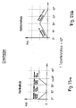
- Fig. 8 is a diagram graphically illustrating the above-described motion sequences wherein the tablet feed is plotted over the rotation of the finger star.
- one tablet cycle corresponds to a rotation of the finger star by 60 °, that is to say six tablets were grasped and advanced during a complete rotation of the finger star through 360 °.
- FIG. 9 shows the second conveyor 20 with its finger wheels 22 arranged parallel to one another and the two pivoting devices or rockers 26 and 28.
- the finger wheel or the finger star 22 is identical in terms of its shape, pitch (six star fingers), its direction of rotation and its rotational speed the previously explained first finger wheel / fingerstem 12.
- the finger star 22 is here in its starting position 0 °. 9 shows the transfer of the tablets from the preceding, first finger star 12 onto the following, second finger star 22, in particular the inlet of the first tablet 1.1 into the second finger star 22.
- the first tablet 1.1 hiebei from behind to the first star fingers 24.1 of the two second finger star 22 at.
- Fig. 10 shows the second conveyor 20 in a position in which the finger star 22 is in a rotational position of 0 ° to 15 °, wherein the two pivoting devices 26, 28 are pivoted in the direction of the respective arrows, while the finger star 22nd continues to turn.
- the finger star 22 in this forward stroke in the conveying direction can perform a linear, planar movement in the guideway 3, so does not move on a circular arc, the pivoting device 28 must move down while the pivoting device 26 in the drawing Fig. 10 of swung left to right.
- there is a pivoting movement of the pivoting device 26 "horizontally forward” while at the same time the pivoting device 28 performs a Ausretesschwenkamba "vertically downwards”.
- the two corresponding star fingers 24.2 have gripped the first tablet 1.1 by a rotation of the parallel arranged finger wheels 22 and push them further forward.
- the tablet 1.1 is released from the jam of the tablets lying behind it, and a gap arises between the first tablet 1.1 and the subsequent second tablet 1.2. In this way, the tablets are separated from the jam of the adjacent tablets.
- the pivoting device 28 compensates for the movement of the axis of the finger wheels 22 caused by the movement of the pivoting device 26 alone on a radius or arcuate path, so that this axis performs a linear, planar movement parallel to the guideway 3.
- FIG. 11 shows the second conveyor 20 approximately in its one end position in the conveying direction, in which the first tablet 1.1 is transferred to the subsequent third conveyor 30.
- This end position is achieved by a movement of the pivoting devices 26, 28 in the direction of the arrows with a simultaneous rotation of the finger wheels 22 in a range of 15 ° to 30 °, the second pivoting device 28 in turn compensates the movement of the first pivoting device 26 with its movement , The first pivoting device 26 is then in the end position of its pivoting movement "horizontally forward", and the second pivoting device 28 is in the end position of its compensatory pivoting movement "vertically upward”.
- the following further tablets 1.2, 1.3, etc. are, as described above, transported by the first finger star 12 further in the direction of the second finger star 22.
- Fig. 12 shows the backward stroke of the second conveyor 22, wherein the finger wheels 22 opposite to the conveying direction outside the guide track 3 in its initial position be returned by dipping the finger stars 22 under the guideway 3 and conveyed thereon, subsequent tablets. While the finger wheels 22 are in a rotational position of about 30 ° to 40 °, the second pivoting device 28 performs a pivotal movement "vertically downwards" and the first pivoting device 26 a pivotal movement "horizontally backwards".
- FIG. 13 shows an intermediate position of the return stroke of the second conveyor 20, in which the finger wheels 22 are in a rotational position of approximately 45 °, in which the second pivoting device 28 remains in a rest position, and in which the first pivoting device 26 their pivotal movement "horizontally backwards "continues.
- Fig. 14 shows a further intermediate position of the second conveyor 20, in which the finger star 22 is in a rotational position of about 45 ° to 50 °, in which the second pivoting device 28 remains in the rest position, and in which the first pivoting device 26 their Pivoting movement "horizontal backwards" continues.
- Fig. 15 shows the finger star 22 of the second conveyor 20 in a rotational position of about 50 ° to 60 °, wherein the second pivoting device 28 moves in an end position of its pivotal movement "vertically upward", while the first pivoting device 26 in an end position of her Pivoting movement "horizontal backwards” moves.
- the second conveyor 20 is thus again in its initial position, and the directions of movement of the two pivoting devices 26, 28 are reversed.
- FIG. 16 is a graph similar to FIG. 8, showing the tablet advancing over the revolution of the finger stars 22 (term “star fingers movable") of the second conveyor 20, wherein a tablet cycle in turn corresponds to a rotation of the finger star by 60 °.
- Figures 17a and 17b show schematically the above-described movement sequence of the two pivoting devices 26 and 28.
- Figure 17a shows the vertical stroke of the second pivoting device 28 with respect to the rotation of the star fingers;
- Fig. 17b shows the horizontal stroke of the first pivoting device 26 also with respect to the rotation of the star fingers.
- the tablet is transferred to the third conveyor 30, namely at a rotational position of 30 ° of the finger star 22 of the second conveyor 20 (see also FIG. 17b).
- Fig. 18 shows schematically the above-mentioned end position of the second conveyor 20 and the acquisition of the first tablet 1.1 by the insertion device 32 with the rotatably mounted thereon Einschiebefinger 34, then the tablet 1.1 from the end position of the second conveyor 20 between the sealing rollers 50, 60th inserts.
- the insertion device 32 is in the illustration of FIG. 18 in a starting position of 0 °.
- the insertion finger 34 is lowered in a tablet cycle position of the insertion device 32 between 0 ° and about 15 ° down into the guideway 3, while the insertion device 32 simultaneously performs a movement "horizontally forward".
- the tablet 1.1 is gripped by the insertion finger 34 and further advanced and finally inserted between the sealing rollers 50, 60.
- the inserter 32 continues to move "horizontally forward” between a position of about 15 ° to about 30 °, while the inserter finger 34 is constantly in a lowered, “vertical” lower position to advance the tablet further ,
- the insertion device has reached its end position and the tablet is now accurately positioned on the sealing yards 52, 62 of the sealing rollers 50, 60th
- the inserter 32 is subsequently retracted from the aforesaid end position, that is, the inserter 32 performs a "horizontal backward” movement while simultaneously raising the inserter “vertically” to yield to the subsequent tablet 1.2.
- Fig. 21 shows the insertion device in a tablet cycle position of about 40 °.
- Fig. 22 shows the insertion device 32 finally in its initial position, that is a tablet cycle position of 60 °, at the end of its movement section "horizontally backwards".
- the insertion finger 34 is constantly in its "vertical” upper position to the retraction of the Insertion device 32 does not collide with the subsequent tablet 1.2.
- the tablet 1.1 has been further promoted by the sealing rollers 50, 60 in the meantime.
- it is already securely in the four-edge seal bag formed by the heat-sealing foils sealed with each other, which is already about 80% completed.
- Figures 23a and 23b graphically depict the previously described trajectory of the inserter 32 with the insertion finger 34.
- Figure 23a shows the vertical stroke of the inserter 34 during a tablet cycle (60 °);
- Fig. 23b also shows the horizontal stroke of the push-in device 32 during a tablet cycle (60 °).
Abstract
Description
Die Erfindung betrifft eine Vorrichtung zum Zuführen von flachen, scheibenförmigen Gegenständen, wie pharmazeutischen Komprimaten und ähnlich gearteten technischen Kleinteilen, insbesondere Tabletten, zu Siegelwerkzeugen für ein Versiegeln der Gegenstände in Verpackungsfolie, entsprechend dem Oberbegriff des Patentanspruchs 1.The invention relates to a device for feeding flat, disc-shaped objects, such as pharmaceutical tablets and similar technical small parts, in particular tablets, to sealing tools for sealing the objects in packaging film, according to the preamble of
Die Erfmdung wird nachfolgend am Beispiel von kreisförmigen Tabletten, wie beispielsweise Brausetabletten, mit einem Durchmesser im Bereich von ca. 16 bis 30 mm und einer Dicke im Bereich von ca. 3 bis 8 mm, erläutert. Die Tabletten werden von Siegelvorrichtungen einzeln in so genannte Vierrandsiegelbeutel eingesiegelt, wobei zur Bildung der Siegelbeutel typischerweise zwei als Endlosstreifen bereitgestellte Heißsiegelfolien, beispielsweise Aluminium-kaschierte Folien, aufeinandergesiegelt werden. Mehrere derartige Vierrandsiegelbeutel können als Endlosband und nach dessen Aufteilen in Form unterschiedlich großer Verpakkungseinheiten streifenförmig zusammenhängen. Sofern nachfolgend von Tabletten gesprochen wird, versteht sich dieses stellvertretend für jegliche Art von flachen, scheibenförmigen Gegenständen oder entsprechenden technischen Kleinteilen, die in gleicher Weise verpackt werden. Dabei geht es immer um die Förderung und Verpackung der Gegenstände in hohen Stückzahlen bei hohen Fördergeschwindigkeiten.The invention is explained below using the example of circular tablets, such as effervescent tablets, with a diameter in the range of about 16 to 30 mm and a thickness in the range of about 3 to 8 mm. The tablets are individually sealed by sealing devices into so-called four-edge sealing bags, wherein two heat-sealing foils, for example aluminum-laminated foils, provided as endless strips, are typically sealed together to form the sealed pouches. Several such four-edge seal bags can be connected in a strip shape as an endless belt and after its division into differently sized packaging units. As hereinafter referred to as tablets, this is understood as representative of any type of flat, disc-shaped objects or corresponding technical small parts that are packaged in the same way. It is always about the promotion and packaging of the articles in high quantities at high conveyor speeds.
Bei derartigen Verpackungsmaschinen ist es bekannt und in der Praxis üblich, dass einzelne Tabletten aus einer Tablettenzufiihrung im freien Fall lotrecht oder vertikal zu der Siegelstation zugeführt werden, indem sie von oben zwischen zwei Heißsiegelwerkzeuge, insbesondere rotierende Heißsiegelwalzen, hineinfallen, über die von beiden äußeren Seiten her jeweils eine Heißsiegelfolie zugeführt wird. Mittels der Förderung durch die Siegelwalze werden die Tabletten zwischen den Folien eingesiegelt.In such packaging machines, it is known and common in practice that individual tablets are supplied from a tablet supply in free fall vertically or vertically to the sealing station by falling in from above between two heat sealing tools, in particular rotating heat seal rollers, over from both outer sides here in each case a heat-sealing film is supplied. By means of the conveyance through the sealing roller, the tablets are sealed between the films.
Diese vertikale Zuführung der Tabletten zu der Siegelvorrichtung hat mehrere Nachteile: In der Phase des freien Falls bewegt sich die Tablette abhängig von ihrer Masse unkontrolliert derart, dass unterschiedliche Fallzeiten und Positionierungen der Tabletten zwischen den Siegelwalzen auftreten können, was zu unterschiedlichen Positionen der jeweiligen Tablette in dem gebildeten Siegelrandbeutel führen kann. Das Verhalten der Tablette in der Phase des freien Falls kann auch durch eine Verschmutzung der Tablettenzuführung und einen dadurch möglicherweise bedingten Klebeeffekt beeinflußt werden, wodurch die Tabletten zu unterschiedlichen Zeitpunkten von der Tablettenzuführung in den freien Fall übergeben werden. Auch durch unterschiedliche Mitnahmewirkungen zwischen der Folie und der Tablette, beispielsweise bedingt durch verschiedene Folienqualitäten, kann die Lage der jeweiligen Tablette in dem Beutel unterschiedlich sein. Im Ergebnis kann dieses zu minderwertigen oder sogar unbrauchbaren fertigen Verpackungen führen, insbesondere dann, wenn die Tablette nicht korrekt in der Siegelvertiefung (Siegelhof) der Siegelwalze zu liegen kommt, sondern zwischen die Siegelflächen fällt, wo sie zerdrückt werden kann. Darüberhinaus können unbrauchbare (zum Beispiel undichte) Siegelbeutel durch unkontrolliert aus der Tablettenzuführung herabfallende Tablettenbruchstücke resultieren, die wiederum im Bereich der Siegelflächen (Siegelstege) zu liegen kommen und die Heißsiegelfolie dort beschädigen können. Im Fall der vertikalen Zuführung der Tabletten besteht schließlich eine Gefahr durch sich lösende mechanische Bauteile der Tablettenzufürung im Bereich über den Siegelwalzen, wobei derartige Teile zwischen die Siegelwalzen fallen und diese beschädigen können. Weitere Aspekte und Nachteile einer vertikalen Tablettenzuführung ergeben sich aus dem einleitenden Beschreibungsteil der
Zur Überwindung der Nachteile einer vertikalen Tablettenzuführung, wie zuvor beschrieben, wurde gemäß der
In der Praxis hat sich diese Lösung jedoch nicht ausreichend bewährt, da die gewünschte sichere und exakte Positionierung der Tabletten in den Siegelhöfen der Siegelwalzen nicht ausreichend gut erzielt wird. Die Siegelhöfe in den Siegelwalzen können in ihrer Größe daher nicht auf ein Minimum reduziert werden, was andererseits wünschenswert wäre, um letztlich möglichst kleine, Platz und Material sparende und damit kostengünstigere Verpackungseinheiten herzustellen.In practice, however, this solution has not proven sufficiently, since the desired safe and accurate positioning of the tablets in the sealing courts of the sealing rollers is not sufficiently well achieved. The sealing yards in the sealing rolls can therefore not be reduced in size to a minimum, which would be desirable on the other hand to ultimately produce the smallest possible, space and material-saving and thus more cost-effective packaging units.
Ausgehend von diesen bekannten Zuführvorrichtungen liegt der Erfindung somit die Aufgabe zugrunde, die oben genannten Nachteile des Standes der Technik zu überwinden und insbesondere die Positionierung der Tabletten in den Siegelhöfen der Siegelwerkzeuge und damit in den einzelnen Siegelpackungen zu verbessern und insbesondere eine sichere und exakte, reproduzierbare Positionierung der Tabletten darin zu erreichen.Based on these known feeding devices, the invention is therefore based on the object to overcome the above-mentioned disadvantages of the prior art and in particular to improve the positioning of the tablets in the sealing yards of the sealing tools and thus in the individual sealed packages and in particular a safe and accurate, reproducible Positioning the tablets in reach.
Diese Aufgabe wird durch eine Zuführvorrichtung gemäß Patentanspruch 1 gelöst. Demnach weist die Vorrichtung zum Zuführen der flachen, scheibenförmigen Gegenstände, insbesondere Tabletten, zu den Siegelwerkzeugen neben einer im Wesentlichen horizontal angeordneten Führungsbahn für die Gegenstände, einer in die Führungsbahn eingreifenden ersten Fördereinrichtung, die die Gegenstände im Stau aneinander anliegend vorschiebt, und einer in die Führungsbahn eingreifenden zweiten Fördereinrichtung, die die Gegenstände aus dem Stau vereinzelt und weiter vorschiebt, zusätzlich eine dritte Fördereinrichtung auf, die die vereinzelten Gegenstände von der Führungsbahn im Wesentlichen horizontal positionsgerecht in die Siegelwerkzeuge einschiebt.This object is achieved by a feeding device according to
Die den Siegelwerkzeugen vorgeschaltete erste, zweite und dritte Fördereinrichtung sind in Förderrichtung derart hintereinander angeordnet, dass Zuführung, Vereinzelung, Positionierung und Versiegelung der Tabletten in einer horizontalen Ebene stattfinden. Durch das aufeinander abgestimmte Zusammenwirken der drei Fördereinrichtungen wird eine permanente Zwangsführung der Tabletten und damit eine sichere und genaue Positionierung der Tabletten in den Siegelhöfen der Siegelwerkzeuge erzielt. Die Tabletten werden direkt, kontinuierlich, takt- und maßgenau in den von den Siegelwerkzeugen teilgefertigten Vierrandsiegelbeutel eingeschoben, wobei die Masse und eine Fallbeschleunigung der Tabletten irrelevant sind.The first, second and third conveying means upstream of the sealing tools are arranged one behind the other in the conveying direction such that feeding, singulation, positioning and sealing of the tablets take place in a horizontal plane. Due to the coordinated interaction of the three conveyors a permanent positive guidance of the tablets and thus a secure and accurate positioning of the tablets is achieved in the sealing courts of the sealing tools. The tablets are inserted directly, continuously, with tact and exactness into the four-cornered sealing bags partially manufactured by the sealing tools, whereby the mass and a case acceleration of the tablets are irrelevant.
Durch die erfindungsgemäße Vorrichtung werden die oben beschriebenen Nachteile sowohl der vertikalen Zuführvorrichtung als auch der bereits bekannten horizontalen Zufiihrvorrichtung beseitigt. So überwindet die dritte Fördereinrichtung einen durch eine Verschmutzung der Zuführungsbahn bedingten Klebeeffekt, das heißt die Tabletten werden nicht mehr durch ein Klebenbleiben an der Zuführungsbahn abgebremst, sondern mit der von der dritten Fördereinrichtung aufgebrachten Geschwindigkeit kontinuierlich in die Siegelwalzen eingeschoben. Da die Tablettenzuführung seitlich neben den Siegelwalzen angeordnet ist, besteht des Weiteren keine Gefahr, dass die Siegelwalzen durch sich lösende, herabfallende mechanische Bauteile beschädigt werden, und herabfallende Tablettenbruchstücke gelangen nicht mehr zwischen die Siegelwalzen, sondern außerhalb des Siegelbereichs in geeignete Auffangbehälter. Die horizontale Anordnung der Tablettenzuführung vor den Siegelwerkzeugen bedingt darüber hinaus eine geringe Einbauhöhe der Tablettenzuführung (zum Beispiel ca. 1000 mm über dem Boden), wodurch die Vorrichtung insgesamt gut einsehbar und bedienerfreundlich ist.The device according to the invention eliminates the above described disadvantages of both the vertical feeder and the already known horizontal feeder. Thus, the third conveyor overcomes a contamination caused by contamination of the feed path adhesive effect, that is, the tablets are no longer braked by sticking to the feed path, but continuously inserted at the speed applied by the third conveyor speed in the sealing rollers. Furthermore, since the tablet feeder is arranged laterally adjacent to the sealing rolls, there is no danger that the sealing rolls will be damaged by falling, falling mechanical components, and falling tablet fragments no longer reach between the sealing rolls but outside the sealing area into suitable collecting containers. The horizontal arrangement of the tablet feed before the sealing tools also requires a low installation height of the tablet feed (for example, about 1000 mm above the ground), whereby the device is overall well visible and easy to use.
Gemäß bevorzugten Ausführungsformen der erfindungsgemäßen Zuführvorrichtung weisen die erste und die zweite Fördereinrichtung jeweils eine Fingerwalze oder ein Paar parallel zueinander angeordneter Fingerräder auf, deren Finger bei einer Drehung die zu fördernden Gegenstände ergreifen und vorschieben. Die zweite Fördereinrichtung weist darüber hinaus Einrichtungen für eine Verschiebung der Achse ihrer Fingerwalze oder ihrer Fingerräder in Förderrichtung auf, insbesondere eine erste Verschiebe- oder Schwenkeinrichtung für eine im wesentlichen horizontale Verschiebung der Fingerwalze/Fingerräder parallel zur Führungsbahn, sowie eine zweite Verschiebe- oder Schwenkeinrichtung für eine im wesentlichen vertikale Verschiebung der Fingerwalze/Fingerräder senkrecht zur Führungsbahn, wobei die beiden miteinander gekoppelten Verschiebe- oder Schwenkeinrichtungen kombinierte Verschiebe- oder Schwenkbewegungen ausführen. Die dritte Fördereinrichtung weist eine parallel zur Führungsbahn verschiebbare Einschiebeeinrichtung auf, die einen im wesentlichen senkrecht zur Führungsbahn bewegbaren, insbesondere verschwenkbar gelagerten Einschiebefinger umfasst.According to preferred embodiments of the feeding device according to the invention, the first and the second conveyor each have a finger roller or a pair of parallel arranged finger wheels, whose fingers take the objects to be conveyed during rotation and advancing. The second conveyor further comprises means for shifting the axis of its finger roller or its finger wheels in the conveying direction, in particular a first displacement or pivoting device for a substantially horizontal displacement of the finger roller / finger wheels parallel to the guide track, and a second displacement or pivoting device for a substantially vertical displacement of the finger roller / finger wheels perpendicular to the guide track, wherein the two mutually coupled displacement or pivoting devices perform combined sliding or pivoting movements. The third conveyor has a sliding parallel to the guide rail insertion means comprising a substantially perpendicular to the guide track movable, in particular pivotally mounted insertion fingers.
Durch eine mechanische Kopplung und/oder Synchronisierung der ersten, zweiten und dritten Fördereinrichtungen miteinander und/oder mit den Siegelwerkzeugen sowie durch eine entsprechende Anbindung an den Hauptantrieb der Verpackungsmaschine kann der takt- und maßgenaue Einschub der Tabletten in die Siegelvorrichtung und damit die genaue Lage der Tablette in der zu bildenden Siegelverpackung bei jeder beliebigen Maschinengeschwindigkeit und insbesondere bei variierenden Maschinengeschwindigkeiten bewerkstelligt werden. Mit der erfindungsgemäßen Zuführvorrichtung sind schließlich insgesamt höhere Förder- und Arbeitsgeschwindigkeiten möglich als bei den bekannten Zuführvorrichtungen. So können mit der erfindungsgemäßen horizontalen Zuführvorrichtung typischerweise Fördergeschwindigkeiten von ca. 350 Tabletten pro Bahn pro Minute realisiert werden.By a mechanical coupling and / or synchronization of the first, second and third conveyors with each other and / or with the sealing tools and by a corresponding connection to the main drive of the packaging machine, the clock and dimensionally accurate insertion of the tablets in the sealing device and thus the exact location of the Tablet can be accomplished in the sealed package to be formed at any machine speed and in particular at varying machine speeds. With The delivery device according to the invention, finally, overall higher delivery and operating speeds are possible than in the known feeders. Thus, with the horizontal feeding device according to the invention, conveying speeds of approximately 350 tablets per line per minute can typically be achieved.
Weitere Vorteile und Einzelheiten der Erfindung ergeben sich aus der nachfolgenden Beschreibung eines Ausführungsbeispiels anhand der Zeichnungen.
- Fig. 1 - 7
- zeigen in mehreren Schritten die Funktionsweise der als Fingersternpaar ausgebildeten ersten Fördereinrichtung, jeweils in einer Seitenansicht, einer Draufsicht von oben, und einer Querschnittsansicht (Schnitt A-A).
- Fig. 8
- ist ein Diagramm zur Erläuterung der Drehbewegung des ersten Fingersternpaars und des entsprechenden Tablettenvorschubs.
- Fig. 9 - 15
- zeigen in mehreren Schritten die Funktionsweise des mit zwei Schwenkeinrichtungen gekoppelten Fingersternpaars der zweiten Fördereinrichtung, jeweils in einer Seitenansicht und einer Draufsicht von oben.
- Fig. 16
- ist ein Diagramm zur Erläuterung der Drehbewegung des zweiten Fingersternpaars und des entsprechenden Tablettenvorschubs.
- Fig. 17a und b
- sind Diagramme zur Erläuterung der Schwenkbewegungen der beiden Schwenkeinrichtungen der zweiten Fördereinrichtung.
- Fig. 18 - 22
- zeigen in mehreren Schritten die Funktionsweise der Einschiebeeinrichtung der dritten Fördereinrichtung, jeweils in einer Seitenansicht.
- Fig. 23a und 23b
- sind Diagramme zur Erläuterung der Hubbewegungen der Einschiebeeinrichtung der dritten Fördereinrichtung.
- Fig. 24
- ist eine Gesamtdarstellung der horizontalen Zuführvorrichtung in einer den Fig. 11 und 18 entsprechenden Position der drei Fördereinrichtungen und der sich anschließenden Siegelwalzen, in einer Seitenansicht.
- Fig. 1-7
- show in several steps the operation of the trained as a finger star pair first conveyor, each in a side view, a top view from above, and a cross-sectional view (section AA).
- Fig. 8
- is a diagram for explaining the rotational movement of the first pair of finger star and the corresponding tablet feed.
- Fig. 9 - 15
- show in several steps the operation of coupled to two pivoting finger star pair of the second conveyor, each in a side view and a top view.
- Fig. 16
- is a diagram for explaining the rotational movement of the second pair of finger star and the corresponding tablet feed.
- Fig. 17a and b
- are diagrams for explaining the pivoting movements of the two pivoting means of the second conveyor.
- Fig. 18 - 22
- show in several steps the operation of the insertion device of the third conveyor, each in a side view.
- Figs. 23a and 23b
- are diagrams for explaining the strokes of the insertion device of the third conveyor.
- Fig. 24
- is an overall view of the horizontal feeder in a corresponding to Figs. 11 and 18 position of the three conveyors and the subsequent sealing rollers, in a side view.
Für die nachfolgende Detaildarstellung wird von einem beispielhaften Tablettendurchmesser von 25 mm ausgegangen. Bei der hier dargestellten, beispielhaften "Teilung" von sechs Fingern pro Fingerstern, wobei die Finger unter einem gleichmäßigen Winkelabstand von 60° zueinander am Umfang des Fingersterns angeordnet sind, wird bei einer Drehbewegung des Fingersterns um 60° jeweils eine Tablette von einem der sechs Finger ergriffen und weitertransportiert. Eine Drehbewegung des Fingersterns um 60° entspricht somit einem Tablettenzyklus (siehe Figuren 8, 16, 17a, 17b, 23a und 23b).For the following detailed representation, an exemplary tablet diameter of 25 mm is assumed. In the exemplary "division" of six fingers per finger star shown here, wherein the fingers are arranged at a uniform angular distance of 60 ° to each other on the circumference of the finger star, a rotation of the finger star by 60 ° in each case a tablet of one of the six fingers seized and transported on. A rotational movement of the finger star by 60 ° thus corresponds to a tablet cycle (see FIGS. 8, 16, 17a, 17b, 23a and 23b).
Abhängig vom Tablettendurchmesser sind auch andere Fingersternteilungen möglich, beispielsweise mit fünf oder sieben Fingern. In diesen Fällen gelten für die beigefügten Zeichnungen andere Längen und Winkelangaben. Grundsätzlich ist die Form und Lage der Fingersterne immer auf den Tablettendurchmesser abgestimmt.Depending on the diameter of the tablet, other finger-stem divisions are also possible, for example with five or seven fingers. In these cases, other lengths and angles will apply to the attached drawings. Basically, the shape and position of the finger stars is always matched to the diameter of the tablet.
Anhand von Fig. 24 wird zunächst die Zuführvorrichtung insgesamt dargestellt. In einer Führungsbahn 3 werden die Tabletten flach liegend von links nach rechts zu den Siegelwalzen 50, 60 zugeführt. In die Führungsbahn 3 greift eine erste Fördereinrichtung 10 ein, die aus einem Paar von parallel zueinander angeordneten Fingerrädern oder Fingersternen 12 gebildet ist, die um eine zur Förderrichtung der Zuführvorrichtung senkrechte und zur Ebene der Führungsbahn 3 parallele Achse drehbar sind. Jeweils ein Fingerrad 12 ist seitlich außerhalb der Mittellinie der Führungsbahn 3 angeordnet, so dass Finger (Sternfinger) 14, die sternförmig am Umfang jedes Fingerrads 12 angeordnet sind, in zwischen den aneinander anliegenden Tabletten 1 gebildete Freiräume eingreifen und bei einer Drehung des Paars der Fingerräder 12 um ihre Achse eine Tablette 1 ergreifen und vorschieben. Die Anordnung der beiden Fingeräder 12 seitlich außerhalb der Mittellinie der Führungsbahn 3 ist insbesondere aus der Draufsicht von oben gemäß den Figuren 1 bis 7 ersichtlich.With reference to Fig. 24, first, the feeding device is shown as a whole. In a
Wie oben schon ausgeführt wurde, sind in dieser Ausführungsform sechs Finger (Sternfinger) 14 unter einem gleichmäßigen Winkelabstand von jeweils 60° am Umfang der Fingerräder 12 angeordnet (Sternfingerteilung "Sechs"). Durch ein kontinuierliches Drehen der Fingerräder bzw. Fingersterne 12 im Uhrzeigersinn wird bei dieser Sternfmgerteilung somit bei einer Drebewegung um 60° immer eine Tablette von einem Finger 14 des ersten Fingerrads sowie dem entsprechenden Finger 14 des parallel dazu angeordneten zweiten Fingerrads ergriffen und weitertransportiert (entsprechend einem Tablettenzyklus). Der jeweils nachfolgende Finger an den beiden parallelen Fingersternen hält die nachfolgenden weiteren Tabletten 1 auf Stau.As stated above, in this embodiment, six fingers (star fingers) 14 are arranged at a uniform angular distance of 60 ° each on the circumference of the finger wheels 12 (star finger pitch "six"). By means of a continuous rotation of the finger wheels or finger stars 12 in the clockwise direction, a tablet of a
Abgesehen von der beschriebenen Drehbewegung ist das Paar der Fingerräder 12 feststehend im Bereich der Führungsbahn 3 angeordnet, das heißt die Achse der Fingerräder 12 ist nicht verschiebbar, insbesondere nicht in der Förderrichtung der Tablettenzuführvorrichtung (Bezeichnung "Sternfinger Fix" in dem Diagramm der Fig. 8).Apart from the rotational movement described, the pair of
Fig. 24 zeigt des Weiteren eine in die Führungsbahn eingreifende zweite Fördereinrichtung 20, die die Tabletten 1 aus dem Stau vereinzelt und weiter in Richtung der Siegelwalzen 50, 60 vorschiebt. Die zweite Fördereinrichtung 20 weist im Bereich der Führungsbahn 3 wiederum ein Paar von drehbar gelagerten Fingerrädern oder Fingersternen 22 auf, die wiederum an ihrem Umfang sternförmig angeordnete Finger (Sternfinger) 24 haben. Die Form, Fingerteilung, Drehrichtung und Drehgeschwindigkeit dieser Fingerräder 22 stimmt mit den Fingerrädern 12 der ersten Fördereinrichtung 10 überein.FIG. 24 furthermore shows a second conveying
Die zweite Fördereinrichtung 20 weist darüber hinaus Einrichtungen 26, 28 für eine Verschiebung der Achse ihrer Fingerräder 22 in der Förderrichtung der Zuführvorrichtung auf. Hierbei handelt es sich insbesondere um eine drehbar gelagerte Schwenkeinrichtung oder Schwinge 26 für eine horizontale Verschiebung der Fingerräder 22 parallel zur Führungsbahn 3 sowie um eine drehbar gelagerte Schwenkeinrichtung oder Schwinge 28 für eine vertikale Verschiebung der Fingerräder 22 senkrecht zur Führungsbahn 3. Wie aus Fig. 24 ersichtlich ist, ist die Achse der Fingerräder 22 an der Schwenkeinrichtung 26 für die horizontale Verschiebung gelagert, und diese Schwenkeinrichtung 26 ist wiederum an der Schwenkeinrichtung 28 für die vertikale Verschiebung der Fingerräder 22 gelagert. Diese beiden Schwenkeinrichtungen oder Schwingen 26, 28 führen somit kombinierte Schwenkbewegungen derart aus, dass die Fingerräder 22 bei einem Vorwärtshub in Förderrichtung eine im wesentlichen lineare Bewegung in der Führungsbahn 3 in Richtung zu den Siegelwalzen 50, 60 hin ausführen, und dass die Fingerräder 22 bei einem Rückwärtshub entgegengesetzt zur Förderrichtung außerhalb der Führungsbahn 3 in ihre Ausgangsposition zurückführbar sind. Dieser Bewegungsablauf wird unten in Bezug auf die Figuren 9 bis 15 noch detaillierter erläutert.The
Fig. 24 zeigt schießlich eine dritte Fördereinrichtung 30, die die vereinzelten Tabletten von der Führungsbahn 3 horizontal positionsgerecht in die Siegelhöfe 52, 62 der Siegelwalzen 50, 60 einschiebt. Insbesondere weist die dritte Fördereinrichtung 30 dafür eine parallel zur Führungsbahn 3 verschiebbare Einschiebeeinrichtung 32 auf, an der ein im Wesentlichen senkrecht zur Führungsbahn 3 bewegbarer Einschiebefinger 34 angebracht ist. Dabei ist der Einschiebefmger 34 insbesondere um eine zur Förderrichtung senkrechte und zur Ebene der Führungsbahn 3 parallele Achse drehbar in der Einschiebeeinrichtung 32 gelagert. Der Einschiebefinger 34 führt einen Bewegungsablauf derart aus, dass er bei einem Vorwärtshub der Einschiebeeinrichtung 32 in Förderrichtung im Wesentlichen vertikal so positioniert ist, dass er die Tablette 1 ergreift und in die Siegelwalzen 50, 60 einschiebt, und dass er bei einem Rückwärtshub der Einschiebeeinrichtung 32 entgegengesetzt zur Förderrichtung im Wesentlichen vertikal so positioniert ist, dass er außerhalb der Führungsbahn 3 in seine Ausgangsposition zurückführbar ist. Dieser Bewegungsablauf wird unten mit Bezug auf die Figuren 18 bis 23 noch detaillierter beschrieben.Finally, FIG. 24 shows a third conveying
Wie aus Fig. 24 schließlich auch ersichtlich ist, schließen sich an die horizontale Tablettenzuführvorrichtung seitlich an sich bekannte Siegelwerkzeuge 50, 60 an. Hierbei handelt es sich insbesondere um oberhalb und unterhalb der Ebene der Führungsbahn 3 parallel zueinander angeordnete, aneinander anliegende, rotierende Heißsiegelwalzen 50, 60, über die von außen Heißsiegelfolien (nicht dargestellt) zur Bildung von Siegelverpackungen in die Ebene der Führungsbahn 3 zugeführt werden. Die Heißsiegelwalzen 50, 60 weisen an ihrem Umfang Siegelhöfe 52, 62 auf, in denen die Tabletten aufgenommen und zwischen den Heißsiegelfolien eingesiegelt werden. Typischerweise haben die Siegelhöfe 52, 62 eine rechteckige, insbesondere quadratische Form, wodurch sich als Verpackung für jeweils eine Tablette ein so genannter Vierrandsiegelbeutel ergibt. Hierbei hängen diese Einzelverpackungen in Form eines Endlosbands zusammen, das von den Heißsiegelwalzen 50, 60 ausgegeben wird. In bekannter Weise wird dieses Band mittels Schneideinrichtungen oder Perforationen in jeweils gewünschte Verpackungseinheiten geteilt, die weiter gefördert und beispielsweise in Kartonverpackungen verpackt werden.Finally, as can also be seen from FIG. 24,
Die Tablettenzuführvorrichtung und die nachgeschalteten Siegelwerkzeuge 50, 60 können mehrbahnig derart ausgeführt sein, dass mehrere horizontale Führungsbahnen 3 parallel nebeneinander angeordnet sind, dass dementsprechend mehrere erste, zweite und dritte Fördereinrichtungen 10, 20, 30 nebeneinander angeordnet sind, und dass die Siegelwerkzeuge 50, 60 dementsprechend für eine gleichzeitige Aufnahme und ein Versiegeln mehrerer Tabletten parallel nebeneinander ausgebildet sind.The tablet feeding device and the
Die Funktionsweise und die einzelnen Ablaufschritte der drei Fördereinrichtungen 10, 20, 30 der Tablettenzuführvorrichtung werden nachfolgend unter Bezugnahme auf die Figuren 1 bis 23 im Detail erläutert. Hierbei wird ein Tablettendurchmesser von 25 mm und eine Fingerstemteilung "Sechs" zugrundegelegt.The mode of operation and the individual sequence steps of the three
Wie aus Fig. 1 ersichtlich ist, werden die Tabletten 1, beispielsweise nach ihrer Herstellung, in die Führungsbahn 3 eingeführt, wo sie auf die zwei paarweise angebrachten Fingerräder oder Fingersterne 12 der ersten Fördereinrichtung 10 treffen. Vor den Fingersternen 12, das heißt in Fig. 1 links davon, ist in der Regel immer ein Tablettenvorrat (Tablettenstau) vorhanden. Wie aus der Draufsicht in Fig. 1 zu erkennen ist, liegt die erste Tablette 1.1 dann an ersten Fingern 14.1 der beiden Fingersterne 12 an, die in die Führungsbahn 3 eingreifen. Für die weitere Erläuterung der Drehbewegung der Fingersterne 12 wird diese Position als "Ausgangsstellung 0°" definiert.As can be seen from FIG. 1, the
Fig. 2 zeigt, wie bei einer Drehung der beiden Fingersterne 12 im Uhrzeigersinn nun die nachfolgenden, zweiten Sternfinger 14.2 von unten in die Führungsbahn 3 eingeschwenkt werden und dabei in die Freiräume eingreifen, die zwischen den aneinander anliegenden Tabletten 1, hier die erste Tablette 1.1 und die zweite Tablette 1.2, gebildet sind. Die Sternfmger 14.2 ergreifen damit die im Stau liegende erste Tablette 1.1 und schieben diese in Förderrichtung vor. Die vor dieser ersten Tablette 1.1 liegenden Sternfinger 14.1 tauchen dabei in die Führungsbahn 3 ab. Fig. 2 zeigt eine Stellung der ersten Sternfinger 14.1 nach einer Drehung um 30°, was unter den oben genannten maßlichen Voraussetzungen einem Tablettenvorschub von ca. 9 mm entspricht.Fig. 2 shows how in a clockwise rotation of the two
Fig. 3 zeigt den Zustand nach einer Drehung der Fingerräder 12 um weitere 30°, das heißt eine Verschwenkung des ersten Sternfingers 14.1. um 60° aus der Ausgangsstellung. Die nachfolgenden zweiten Finger 14.2 ergreifen die erste Tablette 1.1 nun vollständig und schieben diese weiter vor, wobei sie die nachfolgenden Tabletten 1.2, 1.3, etc. auf Stau halten. Die Tabletten wurden bisher somit um 25 mm vorgeschoben, das heißt der vollen Länge einer Tablette.Fig. 3 shows the state after rotation of the
Fig. 4 zeigt den Zustand nach einer Drehung des ersten Sternfingers 14.1 um 90°. Dieses ist eine Zwischenstellung, bei der die erste Tablette 1.1 von den zweiten Fingern 14.2 weitergeschoben wurde und die nachfolgende zweite Tablette 1.2 nun von den wiederum nachfolgenden dritten Sternfingern 14.3 ergriffen und übernommen wird, wobei die Finger 14.3 in die Freiräume zwischen den aneinander anliegenden kreisrunden Tabletten 1.2 und 1.3 eingreifen. Diese "Stellung 90°" des ersten Sternfingers 14.1 entspricht einem Tablettenvorschub von ca. 34 mm, das heißt einer Länge von etwa 1,5 Tabletten.4 shows the state after a rotation of the first star finger 14.1 by 90 °. This is an intermediate position in which the first tablet 1.1 has been pushed further by the second fingers 14.2 and the following second tablet 1.2 is now grasped and taken over by the subsequent third star fingers 14.3, the fingers 14.3 being inserted into the free spaces between the adjacent circular tablets 1.2 and 1.3 intervene. This "position 90 °" of the first star finger 14.1 corresponds to a tablet feed of about 34 mm, that is a length of about 1.5 tablets.
Fig. 5 zeigt den ersten Sternfinger 14.1 in der "Stellung 120°", also in einer Stellung des Fingerrads nach dem Weitertransport von nunmehr zwei Tabletten 1.1 und 1.2. Hierbei übernimmt die zweite Tablette 1.2 den Vorschub für die erste Tablette 1.1. Diese Stellung entspricht einem Tablettenvorschub von 50 mm, also einer Länge von zwei Tabletten.Fig. 5 shows the first star finger 14.1 in the "position 120 °", ie in a position of the finger wheel after the further transport of now two tablets 1.1 and 1.2. in this connection the second tablet 1.2 takes over the feed for the first tablet 1.1. This position corresponds to a tablet feed of 50 mm, so a length of two tablets.
Fig. 6 zeigt die Stellung des ersten Sternfingers 14.1 nach einer Verdrehung um 150°. Dieses ist wiederum eine Zwischenstellung, in der der vierte Sternfinger 14.4 in die Führungsbahn 3 einschwenkt und den Vorschub der dritten Tablette 1.3 übernimmt, während der vorhergehende dritte Sternfinger 14.3 unter die Führungsbahn 3 abtaucht. Die von dem Finger 14.4 ergriffene und vorgeschobene dritte Tablette 1.3 übernimmt damit den Vorschub für die zweite Tablette 1.2 und die erste Tablette 1.1, die im Stau in der Führungsbahn 3 liegen. Diese Stellung entspricht einem Tablettenvorschub um ca. 63 mm von der Ausgangsposition, das heißt einer Länge von ca. 2,5 Tabletten.Fig. 6 shows the position of the first star finger 14.1 after a rotation of 150 °. This, in turn, is an intermediate position in which the fourth star finger 14.4 pivots into the
Fig. 7 zeigt schließlich die Stellung des ersten Sternfingers 14.1 nach einer Drehung des Fingerrads 12 um 180°. Der vierte Sternfinger 14.4 hat die dritte Tablette 1.3 ergriffen und schiebt diese weiter vor, womit auch die davor liegenden ersten und zweiten Tabletten 1.1 und 1.2 weitertransportiert werden. Die in Fig. 7 dargestellte Stellung entspricht einem Tablettenvorschub von 75 mm, das heißt einer Länge von drei Tabletten.Finally, FIG. 7 shows the position of the first star finger 14.1 after a rotation of the
Fig. 8 ist ein Diagramm, das die zuvor beschriebenen Bewegungsabläufe graphisch darstellt, wobei der Tablettenvorschub über der Umdrehung des Fingersterns aufgetragen ist. Aus diesem Diagramm ist unter anderem ersichtlich, dass ein Tablettenzyklus einer Drehung des Fingersterns um 60° entspricht, das heißt bei einer vollen Umdrehung des Fingersterns um 360° sind sechs Tabletten ergriffen und vorgeschoben worden.Fig. 8 is a diagram graphically illustrating the above-described motion sequences wherein the tablet feed is plotted over the rotation of the finger star. Among other things, it can be seen from this diagram that one tablet cycle corresponds to a rotation of the finger star by 60 °, that is to say six tablets were grasped and advanced during a complete rotation of the finger star through 360 °.
Fig. 9 zeigt die zweite Fördereinrichtung 20 mit ihren parallel zueinander angeordneten Fingerrädern 22 und den beiden Schwenkeinrichtungen oder Schwingen 26 und 28. Das Fingerrad bzw. der Fingerstern 22 ist bezüglich seiner Form, Teilung (sechs Sternfinger), seiner Drehrichtung sowie seiner Drehgeschwindigkeit identisch zu dem zuvor erläuterten ersten Fingerrad/Fingerstem 12. Der Fingerstern 22 befindet sich hier in seiner Ausgangsstellung 0°. Fig. 9 zeigt die Übergabe der Tabletten von dem vorhergehenden, ersten Fingerstern 12 auf den nachfolgenden, zweiten Fingerstern 22, insbesondere den Einlauf der ersten Tablette 1.1 in den zweiten Fingerstern 22. Wie insbesondere aus der Draufsicht der Fig. 9 zu erkennen ist, stößt die erste Tablette 1.1 hiebei von hinten an die ersten Sternfinger 24.1 der beiden zweiten Fingersterne 22 an.9 shows the
Fig. 10 zeigt die zweite Fördereinrichtung 20 in einer Stellung, in der sich der Fingerstern 22 in einer Drehstellung von 0° bis 15° befindet, wobei die beiden Schwenkeinrichtungen 26, 28 in Richtung der jeweils eingezeichneten Pfeile verschwenkt werden, während sich der Fingerstern 22 weiter dreht. Damit der Fingerstern 22 bei diesem Vorwärtshub in Förderrichtung eine lineare, ebene Bewegung in der Führungsbahn 3 ausführen kann, also nicht eine Bewegung auf einer Kreisbogenbahn vollzieht, muss die Schwenkeinrichtung 28 sich nach unten bewegen, während die Schwenkeinrichtung 26 in der Zeichnung Fig. 10 von links nach rechts verschwenkt. Es erfolgt also eine Schwenkbewegung der Schwenkeinrichtung 26 "horizontal vorwärts", während gleichzeitig die Schwenkeinrichtung 28 eine Ausgleichsschwenkbewegung "vertikal abwärts" vollzieht.Fig. 10 shows the
Durch eine Drehung der parallel angeordneten Fingerräder 22 haben zwischenzeitich die beiden entsprechenden Sternfinger 24.2 die erste Tablette 1.1 ergriffen und schieben diese weiter vor. Durch die gleichzeitige Bewegung der Schwenkeinrichtung 26 wird die Tablette 1.1 aus dem Stau der dahinter liegenden Tabletten gelöst, und es entsteht eine Lücke zwischen der ersten Tablette 1.1 und der nachfolgenden zweiten Tablette 1.2. Auf diese Weise werden die Tabletten aus dem Stau der aneinander liegenden Tabletten vereinzelt. Die Schwenkeinrichtung 28 gleicht dabei die durch die Bewegung der Schwenkeinrichtung 26 alleine bewirkte Bewegung der Achse der Fingerräder 22 auf einer Radius- oder Kreisbogenbahn aus, so dass diese Achse eine lineare, ebene Bewegung parallel zur Führungsbahn 3 vollzieht.In the meantime, the two corresponding star fingers 24.2 have gripped the first tablet 1.1 by a rotation of the parallel arranged
Fig. 11 zeigt die zweite Fördereinrichtung 20 ungefähr in ihrer einen Endstellung in Förderrichtung, in der die erste Tablette 1.1 an die nachfolgende dritte Fördereinrichtung 30 übergeben wird. Diese Endstellung wird durch eine Bewegung der Schwenkeinrichtungen 26, 28 in Richtung der eingezeichneten Pfeile bei einer gleichzeitigen Verdrehung der Fingerräder 22 in einem Bereich von 15° bis 30° erreicht, wobei die zweite Schwenkeinrichtung 28 mit ihrer Bewegung wiederum die Radiusbewegung der ersten Schwenkeinrichtung 26 ausgleicht. Die erste Schwenkeinrichtung 26 befindet sich dann in der Endstellung ihrer Schwenkbewegung "horizontal vorwärts", und die zweite Schwenkeinrichtung 28 befindet sich in der Endstellung ihrer Ausgleichsschwenkbewegung "vertikal aufwärts". Die nachfolgenden weiteren Tabletten 1.2, 1.3 usw. werden, wie oben beschrieben, durch den ersten Fingerstern 12 weiter in Richtung zu dem zweiten Fingerstern 22 transportiert.FIG. 11 shows the
Fig. 12 zeigt den Rückwärtshub der zweiten Fördereinrichtung 22, bei dem die Fingerräder 22 entgegengesetzt zur Förderrichtung außerhalb der Führungsbahn 3 in ihre Ausgangsposition zurückgeführt werden, indem die Fingersterne 22 unter die Führungsbahn 3 und die darauf geförderten, nachfolgenden Tabletten abtauchen. Während sich die Fingerräder 22 in einer Drehstellung von etwa 30° bis 40° befinden, vollzieht die zweite Schwenkeinrichtung 28 eine Schwenkbewegung "vertikal abwärts" und die erste Schwenkeinrichtung 26 eine Schwenkbewegung "horizontal rückwärts".Fig. 12 shows the backward stroke of the
Fig. 13 zeigt eine Zwischenstellung des Rückhubs der zweiten Fördereinrichtung 20, bei der sich die Fingerräder 22 in einer Drehstellung von ungefähr 45° befmden, bei der die zweite Schwenkeinrichtung 28 in einer Ruheposition verharrt, und bei der die erste Schwenkeinrichtung 26 ihre Schwenkbewegung "horizontal rückwärts" fortsetzt.13 shows an intermediate position of the return stroke of the
Fig. 14 zeigt eine weitere Zwischenstellung der zweiten Fördereinrichtung 20, in der sich der Fingerstern 22 in einer Drehstellung von etwa 45° bis 50° befindet, in der die zweite Schwenkeinrichtung 28 weiterhin in der Ruheposition verharrt, und in der die erste Schwenkeinrichtung 26 ihre Schwenkbewegung "horizontal rückwärts" fortsetzt.Fig. 14 shows a further intermediate position of the
Fig. 15 zeigt den Fingerstern 22 der zweiten Fördereinrichtung 20 in einer Drehstellung von ca. 50° bis 60°, wobei die zweite Schwenkeinrichtung 28 sich in eine Endstellung ihrer Schwenkbewegung "vertikal aufwärts" bewegt, während sich die erste Schwenkeinrichtung 26 in eine Endstellung ihrer Schwenkbewegung "horizontal rückwärts" bewegt. Bei einer Drehstellung von 60° befindet sich die zweite Fördereinrichtung 20 somit wieder in ihrer Anfangsstellung, und die Bewegungsrichtungen der beiden Schwenkeinrichtungen 26, 28 kehren sich um.Fig. 15 shows the
Fig. 16 ist ein der Fig. 8 vergleichbares Diagramm, das den Tablettenvorschub aufgetragen über der Umdrehung der Fingersterne 22 (Bezeichnung "Sternfinger beweglich") der zweiten Fördereinrichtung 20 zeigt, wobei ein Tablettenzyklus wiederum einer Drehbewegung des Fingersterns um 60° entspricht.FIG. 16 is a graph similar to FIG. 8, showing the tablet advancing over the revolution of the finger stars 22 (term "star fingers movable") of the
Die Figuren 17a und 17b zeigen schematisch den oben beschriebenen Bewegungsablauf der beiden Schwenkeinrichtungen 26 und 28. Fig. 17a zeigt den Vertikalhub der zweiten Schwenkeinrichtung 28 gegenüber der Umdrehung der Sternfinger; Fig. 17b zeigt den Horizontalhub der ersten Schwenkeinrichtung 26 ebenfalls gegenüber der Umdrehung der Sternfinger.Figures 17a and 17b show schematically the above-described movement sequence of the two
In der in Fig. 11 dargestellten Endstellung der zweiten Fördereinrichtung 20 wird die Tablette an die dritte Fördereinrichtung 30 übergeben, nämlich bei einer Drehstellung von 30° des Fingersterns 22 der zweiten Fördereinrichtung 20 (siehe auch Fig. 17b).11, the tablet is transferred to the
Fig. 18 zeigt schematisch die zuvor genannte Endstellung der zweiten Fördereinrichtung 20 und die Übernahme der ersten Tablette 1.1 durch die Einschiebeeinrichtung 32 mit dem drehbar daran gelagerten Einschiebefinger 34, die die Tablette 1.1 dann von der Endstellung der zweiten Fördereinrichtung 20 zwischen die Siegelwalzen 50, 60 einschiebt. Bezogen auf einen Tablettenzyklus, der einer Umdrehung der Fingersterne von 60° entspricht, befindet sich die Einschiebeeinrichtung 32 in der Darstellung der Fig. 18 in einer Ausgangsstellung von 0°.Fig. 18 shows schematically the above-mentioned end position of the
Gemäß Fig. 19 wird der Einschiebefinger 34 in einer Tablettenzyklus-Stellung der Einschiebeeinrichtung 32 zwischen 0° und ca. 15° nach unten in die Führungsbahn 3 abgesenkt, während die Einschiebeeinrichtung 32 gleichzeitig eine Bewegung "horizontal vorwärts" ausführt. Dabei wird die Tablette 1.1 von dem Einschiebefinger 34 ergriffen und weiter vorgeschoben und schließlich zwischen die Siegelwalzen 50, 60 eingeschoben. Während dieses Einschiebevorgangs werden die nachfolgenden Tabletten 1.2, 1.3, usw. von der zweiten Fördereinrichtung 20 nachgeschoben, wie es vorstehend erläutert wurde.19, the
Gemäß Fig. 20 bewegt sich die Einschiebeeinrichtung 32 zwischen einer Stellung von ca. 15° bis ca. 30° weiter "horizontal vorwärts", während sich der Einschiebefinger 34 konstant in einer abgesenkten, "vertikal" unteren Position befindet, um die Tablette weiter vorzuschieben. Bei einer Tablettenzyklus-Stellung von 30° hat die Einschiebeeinrichtung ihre Endstellung erreicht und die Tablette liegt nun maßgenau auf Position in den Siegelhöfen 52, 62 der Siegelwalzen 50, 60.Referring to Fig. 20, the
Gemäß Fig. 21 wird die Einschiebeeinrichtung 32 anschließend von der zuvor genannten Endstellung zurückgezogen, das heißt die Einschiebeeinrichtung 32 vollzieht eine Bewegung "horizontal rückwärts", während gleichzeitig der Einschiebefinger "vertikal" angehoben wird, um der nachfolgenden Tablette 1.2 auszuweichen. Fig. 21 zeigt die Einschiebeeinrichtung in einer Tablettenzyklus-Stellung von ca. 40°.Referring to Fig. 21, the
Fig. 22 zeigt die Einschiebeeinrichtung 32 schließlich in ihrer Ausgangsposition, das heißt einer Tablettenzyklus-Stellung von 60°, am Ende ihres Bewegungsabschnitts "horizontal rückwärts". In dieser Bewegungsphase bis zu dieser Endstellung befindet sich der Einschiebefinger 34 konstant in seiner "vertikal" oberen Position, um beim Zurückziehen der Einschiebeeinrichtung 32 nicht mit der nachfolgenden Tablette 1.2 zu kollidieren. Die Tablette 1.1 wurde zwischenzeitlich von den Siegelwalzen 50, 60 weitergefördert. In Fig. 22 liegt sie bereits sicher in dem von den miteinander versiegelten Heißsiegelfolien gebildeten Vierrandsiegelbeutel, der hier bereits zu ungefähr 80% fertiggestellt ist.Fig. 22 shows the
Die Figuren 23a und 23b stellen den zuvor beschriebenen Bewegungsablauf der Einschiebeeinrichtung 32 mit dem Einschiebefinger 34 graphisch dar. Fig. 23a zeigt den Vertikalhub des Einschiebefmgers 34 während eines Tablettenzyklusses (60°); Fig. 23b zeigt den Horizontalhub der Einschiebeeinrichtung 32 ebenfalls während eines Tablettenzyklusses (60°).Figures 23a and 23b graphically depict the previously described trajectory of the
Claims (13)
gekennzeichnet durch
marked by
Applications Claiming Priority (1)
| Application Number | Priority Date | Filing Date | Title |
|---|---|---|---|
| DE102005017509A DE102005017509B3 (en) | 2005-04-15 | 2005-04-15 | Device for feeding of flat, disc-form objects such as pharmaceutical tablets to sealing tools has third feed device which slides separated objects from guide track horizontally positionally correct into sealing tools |
Publications (2)
| Publication Number | Publication Date |
|---|---|
| EP1712473A1 true EP1712473A1 (en) | 2006-10-18 |
| EP1712473B1 EP1712473B1 (en) | 2008-08-20 |
Family
ID=36463452
Family Applications (1)
| Application Number | Title | Priority Date | Filing Date |
|---|---|---|---|
| EP06006884A Active EP1712473B1 (en) | 2005-04-15 | 2006-03-31 | Device for feeeding disc shaped objects, in particular tablets, to a sealing apparatus |
Country Status (4)
| Country | Link |
|---|---|
| EP (1) | EP1712473B1 (en) |
| AT (1) | ATE405491T1 (en) |
| DE (2) | DE102005017509B3 (en) |
| ES (1) | ES2308620T3 (en) |
Families Citing this family (1)
| Publication number | Priority date | Publication date | Assignee | Title |
|---|---|---|---|---|
| DE102014225529A1 (en) * | 2014-12-11 | 2016-06-16 | Robert Bosch Gmbh | Transport device for a packaging machine |
Citations (8)
| Publication number | Priority date | Publication date | Assignee | Title |
|---|---|---|---|---|
| GB972706A (en) * | 1960-02-10 | 1964-10-14 | Kurt Koerber | Conveyor for packing machines |
| AT261496B (en) * | 1964-01-30 | 1968-04-25 | Bockenheimer Brotfabrik Ferdin | Packaging machine, in particular for baked goods |
| US3717236A (en) * | 1970-01-29 | 1973-02-20 | Molins Ltd | Conveying apparatus |
| GB1457611A (en) * | 1973-05-08 | 1976-12-08 | Sapal Plieuses Automatiques | Transfer assembly for a packaging device |
| US5345750A (en) * | 1992-02-06 | 1994-09-13 | Pvt Piepenbrock Verpackungstechnik Gmbh | Apparatus for supplying and sealing flat articles |
| EP1382532A1 (en) * | 2002-07-18 | 2004-01-21 | AETNA GROUP S.p.A. | A device for separating continuously fed products into groups |
| EP1508519A1 (en) * | 2003-08-20 | 2005-02-23 | Mars Incorporated | Method and device for packaging products and array of packaged products |
| US20050061620A1 (en) * | 2001-12-11 | 2005-03-24 | Jean-Christophe Bonnain | Selection system |
-
2005
- 2005-04-15 DE DE102005017509A patent/DE102005017509B3/en not_active Expired - Fee Related
-
2006
- 2006-03-31 EP EP06006884A patent/EP1712473B1/en active Active
- 2006-03-31 DE DE502006001359T patent/DE502006001359D1/en active Active
- 2006-03-31 ES ES06006884T patent/ES2308620T3/en active Active
- 2006-03-31 AT AT06006884T patent/ATE405491T1/en not_active IP Right Cessation
Patent Citations (8)
| Publication number | Priority date | Publication date | Assignee | Title |
|---|---|---|---|---|
| GB972706A (en) * | 1960-02-10 | 1964-10-14 | Kurt Koerber | Conveyor for packing machines |
| AT261496B (en) * | 1964-01-30 | 1968-04-25 | Bockenheimer Brotfabrik Ferdin | Packaging machine, in particular for baked goods |
| US3717236A (en) * | 1970-01-29 | 1973-02-20 | Molins Ltd | Conveying apparatus |
| GB1457611A (en) * | 1973-05-08 | 1976-12-08 | Sapal Plieuses Automatiques | Transfer assembly for a packaging device |
| US5345750A (en) * | 1992-02-06 | 1994-09-13 | Pvt Piepenbrock Verpackungstechnik Gmbh | Apparatus for supplying and sealing flat articles |
| US20050061620A1 (en) * | 2001-12-11 | 2005-03-24 | Jean-Christophe Bonnain | Selection system |
| EP1382532A1 (en) * | 2002-07-18 | 2004-01-21 | AETNA GROUP S.p.A. | A device for separating continuously fed products into groups |
| EP1508519A1 (en) * | 2003-08-20 | 2005-02-23 | Mars Incorporated | Method and device for packaging products and array of packaged products |
Also Published As
| Publication number | Publication date |
|---|---|
| DE502006001359D1 (en) | 2008-10-02 |
| DE102005017509B3 (en) | 2006-06-14 |
| ATE405491T1 (en) | 2008-09-15 |
| ES2308620T3 (en) | 2008-12-01 |
| EP1712473B1 (en) | 2008-08-20 |
Similar Documents
| Publication | Publication Date | Title |
|---|---|---|
| DE60031082T2 (en) | Device for forming successive groups of articles with means for transferring the articles | |
| EP2836447B1 (en) | Device and method for conveying lumpy products | |
| EP2694377B1 (en) | Method and device for packing strip-type objects, especially strips of chewing gum | |
| EP2799348B1 (en) | Method for grouping articles in article bars and grouping device and packaging machine comprising same | |
| DE4441680B4 (en) | Method and apparatus for making twin cigarette packets | |
| DE2630878A1 (en) | METHOD AND DEVICE FOR FOLDING AND SEPARATING DISPOSABLE DIAPERS OR THE SAME WITH STRETCHED ELASTIC TAPE ATTACHED TO A WEB | |
| DE2702041B2 (en) | Device for optionally dividing a number of individual wound rolls of foils or the like. from a feed conveyor via an intermediate conveyor to a number of distribution conveyors | |
| EP2799349A1 (en) | Method for grouping articles in article bars and grouping device and packaging machine comprising one such and control device for product holding device | |
| DE102007037250A1 (en) | Device for transporting containers | |
| DE1786594B2 (en) | Package manufacturing apparatus | |
| DE3736868A1 (en) | Stacking apparatus on packaging machines for bags or the like | |
| DE3414364A1 (en) | CIGARETTE PACKING MACHINES | |
| EP0304736B1 (en) | Method and device for enveloping, especially cigarette packages | |
| EP0987179B1 (en) | Method and apparatus for transferring packages at a piling station | |
| DE60015046T2 (en) | METHOD AND DEVICE FOR TRANSFERRING BLISTER PACKAGING FROM A CUTTING STATION TO A CONVEYOR LINE | |
| CH696035A5 (en) | Device for register exact alignment of sheet material in an apparatus for handling sheet material. | |
| DE2001998A1 (en) | Method and device for delivering objects to a transport device | |
| EP1712473B1 (en) | Device for feeeding disc shaped objects, in particular tablets, to a sealing apparatus | |
| DE2136692A1 (en) | Method and device for collecting and transporting Be holders | |
| CH664126A5 (en) | DEVICE FOR FORMING GROUPS OF UPRIGHT OBJECTS AND METHOD FOR THEIR OPERATION. | |
| EP3459865A1 (en) | Method and apparatus for stacking small-sized products | |
| DE3808157A1 (en) | COIN STACKING DEVICE | |
| EP3160878B1 (en) | Method and device for conveying piece products | |
| DE102016111697A1 (en) | Apparatus and method for transferring multiple parallel product streams into a single product stream or vice versa | |
| DE102017104266B4 (en) | Device for transporting elongated pieces to a receiving location and for depositing it at this location |
Legal Events
| Date | Code | Title | Description |
|---|---|---|---|
| PUAI | Public reference made under article 153(3) epc to a published international application that has entered the european phase |
Free format text: ORIGINAL CODE: 0009012 |
|
| AK | Designated contracting states |
Kind code of ref document: A1 Designated state(s): AT BE BG CH CY CZ DE DK EE ES FI FR GB GR HU IE IS IT LI LT LU LV MC NL PL PT RO SE SI SK TR |
|
| AX | Request for extension of the european patent |
Extension state: AL BA HR MK YU |
|
| 17P | Request for examination filed |
Effective date: 20070413 |
|
| AKX | Designation fees paid |
Designated state(s): AT BE BG CH CY CZ DE DK EE ES FI FR GB GR HU IE IS IT LI LT LU LV MC NL PL PT RO SE SI SK TR |
|
| GRAP | Despatch of communication of intention to grant a patent |
Free format text: ORIGINAL CODE: EPIDOSNIGR1 |
|
| GRAS | Grant fee paid |
Free format text: ORIGINAL CODE: EPIDOSNIGR3 |
|
| GRAA | (expected) grant |
Free format text: ORIGINAL CODE: 0009210 |
|
| AK | Designated contracting states |
Kind code of ref document: B1 Designated state(s): AT BE BG CH CY CZ DE DK EE ES FI FR GB GR HU IE IS IT LI LT LU LV MC NL PL PT RO SE SI SK TR |
|
| REG | Reference to a national code |
Ref country code: GB Ref legal event code: FG4D Free format text: NOT ENGLISH |
|
| REG | Reference to a national code |
Ref country code: CH Ref legal event code: EP Ref country code: CH Ref legal event code: NV Representative=s name: BUGNION S.A. |
|
| REG | Reference to a national code |
Ref country code: IE Ref legal event code: FG4D Free format text: LANGUAGE OF EP DOCUMENT: GERMAN |
|
| REF | Corresponds to: |
Ref document number: 502006001359 Country of ref document: DE Date of ref document: 20081002 Kind code of ref document: P |
|
| REG | Reference to a national code |
Ref country code: ES Ref legal event code: FG2A Ref document number: 2308620 Country of ref document: ES Kind code of ref document: T3 |
|
| PG25 | Lapsed in a contracting state [announced via postgrant information from national office to epo] |
Ref country code: NL Free format text: LAPSE BECAUSE OF FAILURE TO SUBMIT A TRANSLATION OF THE DESCRIPTION OR TO PAY THE FEE WITHIN THE PRESCRIBED TIME-LIMIT Effective date: 20080820 Ref country code: LT Free format text: LAPSE BECAUSE OF FAILURE TO SUBMIT A TRANSLATION OF THE DESCRIPTION OR TO PAY THE FEE WITHIN THE PRESCRIBED TIME-LIMIT Effective date: 20080820 Ref country code: IS Free format text: LAPSE BECAUSE OF FAILURE TO SUBMIT A TRANSLATION OF THE DESCRIPTION OR TO PAY THE FEE WITHIN THE PRESCRIBED TIME-LIMIT Effective date: 20081220 |
|
| PG25 | Lapsed in a contracting state [announced via postgrant information from national office to epo] |
Ref country code: SI Free format text: LAPSE BECAUSE OF FAILURE TO SUBMIT A TRANSLATION OF THE DESCRIPTION OR TO PAY THE FEE WITHIN THE PRESCRIBED TIME-LIMIT Effective date: 20080820 Ref country code: LV Free format text: LAPSE BECAUSE OF FAILURE TO SUBMIT A TRANSLATION OF THE DESCRIPTION OR TO PAY THE FEE WITHIN THE PRESCRIBED TIME-LIMIT Effective date: 20080820 Ref country code: FI Free format text: LAPSE BECAUSE OF FAILURE TO SUBMIT A TRANSLATION OF THE DESCRIPTION OR TO PAY THE FEE WITHIN THE PRESCRIBED TIME-LIMIT Effective date: 20080820 |
|
| PG25 | Lapsed in a contracting state [announced via postgrant information from national office to epo] |
Ref country code: BG Free format text: LAPSE BECAUSE OF FAILURE TO SUBMIT A TRANSLATION OF THE DESCRIPTION OR TO PAY THE FEE WITHIN THE PRESCRIBED TIME-LIMIT Effective date: 20081120 Ref country code: DK Free format text: LAPSE BECAUSE OF FAILURE TO SUBMIT A TRANSLATION OF THE DESCRIPTION OR TO PAY THE FEE WITHIN THE PRESCRIBED TIME-LIMIT Effective date: 20080820 |
|
| PG25 | Lapsed in a contracting state [announced via postgrant information from national office to epo] |
Ref country code: RO Free format text: LAPSE BECAUSE OF FAILURE TO SUBMIT A TRANSLATION OF THE DESCRIPTION OR TO PAY THE FEE WITHIN THE PRESCRIBED TIME-LIMIT Effective date: 20080820 Ref country code: PT Free format text: LAPSE BECAUSE OF FAILURE TO SUBMIT A TRANSLATION OF THE DESCRIPTION OR TO PAY THE FEE WITHIN THE PRESCRIBED TIME-LIMIT Effective date: 20090120 Ref country code: SK Free format text: LAPSE BECAUSE OF FAILURE TO SUBMIT A TRANSLATION OF THE DESCRIPTION OR TO PAY THE FEE WITHIN THE PRESCRIBED TIME-LIMIT Effective date: 20080820 Ref country code: CZ Free format text: LAPSE BECAUSE OF FAILURE TO SUBMIT A TRANSLATION OF THE DESCRIPTION OR TO PAY THE FEE WITHIN THE PRESCRIBED TIME-LIMIT Effective date: 20080820 |
|
| PLBE | No opposition filed within time limit |
Free format text: ORIGINAL CODE: 0009261 |
|
| STAA | Information on the status of an ep patent application or granted ep patent |
Free format text: STATUS: NO OPPOSITION FILED WITHIN TIME LIMIT |
|
| 26N | No opposition filed |
Effective date: 20090525 |
|
| PG25 | Lapsed in a contracting state [announced via postgrant information from national office to epo] |
Ref country code: EE Free format text: LAPSE BECAUSE OF FAILURE TO SUBMIT A TRANSLATION OF THE DESCRIPTION OR TO PAY THE FEE WITHIN THE PRESCRIBED TIME-LIMIT Effective date: 20080820 |
|
| BERE | Be: lapsed |
Owner name: ROMACO PHARMATECHNIK G.M.B.H. Effective date: 20090331 |
|
| PG25 | Lapsed in a contracting state [announced via postgrant information from national office to epo] |
Ref country code: MC Free format text: LAPSE BECAUSE OF NON-PAYMENT OF DUE FEES Effective date: 20090331 |
|
| PG25 | Lapsed in a contracting state [announced via postgrant information from national office to epo] |
Ref country code: SE Free format text: LAPSE BECAUSE OF FAILURE TO SUBMIT A TRANSLATION OF THE DESCRIPTION OR TO PAY THE FEE WITHIN THE PRESCRIBED TIME-LIMIT Effective date: 20081120 |
|
| PG25 | Lapsed in a contracting state [announced via postgrant information from national office to epo] |
Ref country code: BE Free format text: LAPSE BECAUSE OF NON-PAYMENT OF DUE FEES Effective date: 20090331 |
|
| PG25 | Lapsed in a contracting state [announced via postgrant information from national office to epo] |
Ref country code: PL Free format text: LAPSE BECAUSE OF FAILURE TO SUBMIT A TRANSLATION OF THE DESCRIPTION OR TO PAY THE FEE WITHIN THE PRESCRIBED TIME-LIMIT Effective date: 20080820 |
|
| PG25 | Lapsed in a contracting state [announced via postgrant information from national office to epo] |
Ref country code: AT Free format text: LAPSE BECAUSE OF NON-PAYMENT OF DUE FEES Effective date: 20090331 |
|
| PG25 | Lapsed in a contracting state [announced via postgrant information from national office to epo] |
Ref country code: GR Free format text: LAPSE BECAUSE OF FAILURE TO SUBMIT A TRANSLATION OF THE DESCRIPTION OR TO PAY THE FEE WITHIN THE PRESCRIBED TIME-LIMIT Effective date: 20081121 |
|
| PG25 | Lapsed in a contracting state [announced via postgrant information from national office to epo] |
Ref country code: LU Free format text: LAPSE BECAUSE OF NON-PAYMENT OF DUE FEES Effective date: 20090331 |
|
| PG25 | Lapsed in a contracting state [announced via postgrant information from national office to epo] |
Ref country code: HU Free format text: LAPSE BECAUSE OF FAILURE TO SUBMIT A TRANSLATION OF THE DESCRIPTION OR TO PAY THE FEE WITHIN THE PRESCRIBED TIME-LIMIT Effective date: 20090221 |
|
| PG25 | Lapsed in a contracting state [announced via postgrant information from national office to epo] |
Ref country code: TR Free format text: LAPSE BECAUSE OF FAILURE TO SUBMIT A TRANSLATION OF THE DESCRIPTION OR TO PAY THE FEE WITHIN THE PRESCRIBED TIME-LIMIT Effective date: 20080820 |
|
| PG25 | Lapsed in a contracting state [announced via postgrant information from national office to epo] |
Ref country code: CY Free format text: LAPSE BECAUSE OF FAILURE TO SUBMIT A TRANSLATION OF THE DESCRIPTION OR TO PAY THE FEE WITHIN THE PRESCRIBED TIME-LIMIT Effective date: 20080820 |
|
| PGFP | Annual fee paid to national office [announced via postgrant information from national office to epo] |
Ref country code: IE Payment date: 20140324 Year of fee payment: 9 Ref country code: CH Payment date: 20140324 Year of fee payment: 9 |
|
| PGFP | Annual fee paid to national office [announced via postgrant information from national office to epo] |
Ref country code: FR Payment date: 20140319 Year of fee payment: 9 Ref country code: ES Payment date: 20140324 Year of fee payment: 9 |
|
| PGFP | Annual fee paid to national office [announced via postgrant information from national office to epo] |
Ref country code: GB Payment date: 20140324 Year of fee payment: 9 |
|
| REG | Reference to a national code |
Ref country code: CH Ref legal event code: PL |
|
| GBPC | Gb: european patent ceased through non-payment of renewal fee |
Effective date: 20150331 |
|
| REG | Reference to a national code |
Ref country code: FR Ref legal event code: ST Effective date: 20151130 |
|
| REG | Reference to a national code |
Ref country code: IE Ref legal event code: MM4A |
|
| PG25 | Lapsed in a contracting state [announced via postgrant information from national office to epo] |
Ref country code: IE Free format text: LAPSE BECAUSE OF NON-PAYMENT OF DUE FEES Effective date: 20150331 Ref country code: GB Free format text: LAPSE BECAUSE OF NON-PAYMENT OF DUE FEES Effective date: 20150331 Ref country code: LI Free format text: LAPSE BECAUSE OF NON-PAYMENT OF DUE FEES Effective date: 20150331 Ref country code: CH Free format text: LAPSE BECAUSE OF NON-PAYMENT OF DUE FEES Effective date: 20150331 |
|
| PG25 | Lapsed in a contracting state [announced via postgrant information from national office to epo] |
Ref country code: FR Free format text: LAPSE BECAUSE OF NON-PAYMENT OF DUE FEES Effective date: 20150331 |
|
| REG | Reference to a national code |
Ref country code: ES Ref legal event code: FD2A Effective date: 20160427 |
|
| PG25 | Lapsed in a contracting state [announced via postgrant information from national office to epo] |
Ref country code: ES Free format text: LAPSE BECAUSE OF NON-PAYMENT OF DUE FEES Effective date: 20150401 |
|
| REG | Reference to a national code |
Ref country code: DE Ref legal event code: R082 Ref document number: 502006001359 Country of ref document: DE Representative=s name: HUWER & PARTNER PATENT- UND RECHTSANWAELTE PAR, DE |
|
| PGFP | Annual fee paid to national office [announced via postgrant information from national office to epo] |
Ref country code: DE Payment date: 20230331 Year of fee payment: 18 |
|
| PGFP | Annual fee paid to national office [announced via postgrant information from national office to epo] |
Ref country code: IT Payment date: 20230331 Year of fee payment: 18 |