EP1711710B1 - Suction system for a refrigeration compressor - Google Patents
Suction system for a refrigeration compressor Download PDFInfo
- Publication number
- EP1711710B1 EP1711710B1 EP05700236.2A EP05700236A EP1711710B1 EP 1711710 B1 EP1711710 B1 EP 1711710B1 EP 05700236 A EP05700236 A EP 05700236A EP 1711710 B1 EP1711710 B1 EP 1711710B1
- Authority
- EP
- European Patent Office
- Prior art keywords
- cylinder head
- valve plate
- suction
- outlet tube
- set forth
- Prior art date
- Legal status (The legal status is an assumption and is not a legal conclusion. Google has not performed a legal analysis and makes no representation as to the accuracy of the status listed.)
- Not-in-force
Links
- 238000005057 refrigeration Methods 0.000 title claims description 6
- 230000003014 reinforcing effect Effects 0.000 claims description 16
- 238000010276 construction Methods 0.000 description 24
- 239000012530 fluid Substances 0.000 description 8
- 239000000463 material Substances 0.000 description 8
- 238000004891 communication Methods 0.000 description 6
- 238000007789 sealing Methods 0.000 description 5
- 230000006835 compression Effects 0.000 description 3
- 238000007906 compression Methods 0.000 description 3
- 238000009413 insulation Methods 0.000 description 3
- 238000004519 manufacturing process Methods 0.000 description 3
- 238000000034 method Methods 0.000 description 3
- 230000007812 deficiency Effects 0.000 description 2
- 238000013021 overheating Methods 0.000 description 2
- 230000006978 adaptation Effects 0.000 description 1
- 239000000853 adhesive Substances 0.000 description 1
- 230000001070 adhesive effect Effects 0.000 description 1
- 230000000694 effects Effects 0.000 description 1
- 238000010438 heat treatment Methods 0.000 description 1
- 239000007769 metal material Substances 0.000 description 1
- 238000005086 pumping Methods 0.000 description 1
- 238000011144 upstream manufacturing Methods 0.000 description 1
Images

Classifications
-
- F—MECHANICAL ENGINEERING; LIGHTING; HEATING; WEAPONS; BLASTING
- F04—POSITIVE - DISPLACEMENT MACHINES FOR LIQUIDS; PUMPS FOR LIQUIDS OR ELASTIC FLUIDS
- F04B—POSITIVE-DISPLACEMENT MACHINES FOR LIQUIDS; PUMPS
- F04B39/00—Component parts, details, or accessories, of pumps or pumping systems specially adapted for elastic fluids, not otherwise provided for in, or of interest apart from, groups F04B25/00 - F04B37/00
- F04B39/0027—Pulsation and noise damping means
- F04B39/0055—Pulsation and noise damping means with a special shape of fluid passage, e.g. bends, throttles, diameter changes, pipes
- F04B39/0072—Pulsation and noise damping means with a special shape of fluid passage, e.g. bends, throttles, diameter changes, pipes characterised by assembly or mounting
-
- F—MECHANICAL ENGINEERING; LIGHTING; HEATING; WEAPONS; BLASTING
- F04—POSITIVE - DISPLACEMENT MACHINES FOR LIQUIDS; PUMPS FOR LIQUIDS OR ELASTIC FLUIDS
- F04B—POSITIVE-DISPLACEMENT MACHINES FOR LIQUIDS; PUMPS
- F04B39/00—Component parts, details, or accessories, of pumps or pumping systems specially adapted for elastic fluids, not otherwise provided for in, or of interest apart from, groups F04B25/00 - F04B37/00
- F04B39/12—Casings; Cylinders; Cylinder heads; Fluid connections
- F04B39/125—Cylinder heads
-
- Y—GENERAL TAGGING OF NEW TECHNOLOGICAL DEVELOPMENTS; GENERAL TAGGING OF CROSS-SECTIONAL TECHNOLOGIES SPANNING OVER SEVERAL SECTIONS OF THE IPC; TECHNICAL SUBJECTS COVERED BY FORMER USPC CROSS-REFERENCE ART COLLECTIONS [XRACs] AND DIGESTS
- Y10—TECHNICAL SUBJECTS COVERED BY FORMER USPC
- Y10S—TECHNICAL SUBJECTS COVERED BY FORMER USPC CROSS-REFERENCE ART COLLECTIONS [XRACs] AND DIGESTS
- Y10S181/00—Acoustics
- Y10S181/403—Refrigerator compresssor muffler
Definitions
- the present invention refers to a suction system for a refrigeration compressor, particularly for suction systems of the type which presents a suction muffler.
- Refrigeration compressors generally comprise, in the interior of a shell, a motor-compressor assembly having a cylinder block within which is defined a cylinder having an end closed by a cylinder head defining therewithin a housing for adaptation of a suction muffler, and a discharge chamber in selective fluid communication with a compression chamber defined inside the cylinder and which is closed by a valve plate provided between the closed end of the cylinder and the cylinder head, said fluid communication being defined through suction and discharge orifices provided in said valve plate and which are selectively and respectively closed by suction and discharge valves generally carried by the valve plate.
- noise mufflers upstream the suction orifice and downstream the discharge orifice.
- the latter is generally constructed in plastic material.
- the cylinder head usually defines a first element of the compressor discharge muffler and it is usually constructed in metallic material so as to resist the pressure differences to which it is submitted, since its internal face is exposed to the discharge pressure and its external face to the suction pressure.
- suction and discharge orifices for the admission and discharge of gas in relation to the cylinder are normally close to each other, having their spatial distribution usually limited to be contained in the valve plate in the region in which it covers the cylinder, the elements that cover them (suction chamber and cylinder head) present a contiguous section.
- suction chamber and cylinder head present a contiguous section.
- the negative effect of such proximity is that the cylinder head is the warmest point of the compressor and the heat generated thereby is thus easily transmitted to the suction chamber and therefrom to the gas to be drawn by the cylinder. This results in higher overheating of said gas and reduction of yield and capacity, as explained above.
- a known project solution which is normally adopted to define the channels leading to both the suction orifice and the discharge orifice is to make the suction chamber discharge the gas flow in a volume defined by a cavity in the cylinder head and valve plate, as illustrated in figure 2 .
- This construction presents the advantage of being relatively simple to manufacture, requiring components of little geometrical complexity and resulting in a structurally rigid cylinder head, which is very interesting when the working fluid causes great pressure differences and/or the size of this cylinder head is relatively large.
- the mounting process of the suction muffler in the cylinder head requires the inclusion of relatively complex fixation elements, such as threads, or the inclusion of intermediary elements, such as a metallic suction tube, since the material (plastic) of the suction muffler tends to deform with time when submitted to temperatures which in certain cases occur in this region of the compressor, not guaranteeing the necessary reliability in the fixation of the suction muffler to the cylinder head.
- additional elements such as o'rings or gaskets, are usually included to prevent eventual leakages from impairing the attenuation of noise, which is the main function of the suction muffler.
- FIGS 3-4 illustrate another prior art construction for the suction system which avoids the problems mentioned above.
- the suction tube is constructed in plastic material and seated on the valve plate externally to the cylinder head, i.e., the suction tube is not disposed through the interior of the cylinder head, which maintains it spaced from the warmest region of the discharge chamber.
- the temperatures to which the suction tube is submitted are considerably lower than those in the construction described above, thus avoiding the use of intermediary fixation elements of said prior art construction.
- the need for additional sealing elements is eliminated, since said sealing occurs in the interface between the suction tube and the gasket seated against the valve plate.
- a way to overcome the deficiency of structural fragility of this known prior art solution would be the use of materials with a higher modulus of elasticity, but which has the disadvantage of increasing the cost of the component, whether by using a nobler material, or materials that need more complex manufacturing processes.
- Document JP05099141A presents a muffler with an outlet tube having a unique free end to be mounted to the valve plate in order to direct the suction gas flow to two suction orifices of the valve plate.
- the gas flow at the region of the free end of the outlet tube is submitted to a restriction, which implies turbulence in the suction valves of the valve plate, resulting in a flow instability and in an operational difference between the two suction valves, reducing rhe efficiency of the suction process.
- a suction system for a compressor of the type which comprises: a cylinder; a valve plate which is provided with at least one suction orifice, selectively closed by a suction valve, and which closes a cylinder end; a cylinder head mounted against a face of the valve plate opposite to that closing the cylinder and which defines a discharge chamber occupying part of said cylinder head and partially contouring the suction orifice; and a suction muffler comprising a hollow body having an outlet tube projecting therefrom and presenting a free end seated on the valve plate in coaxial alignment with a respective suction orifice, said cylinder head being provided, externally to the discharge chamber, with a reinforcing wall portion which is dimensioned to define an increase in the structural rigidity of the cylinder head, the free end of the outlet tube is provided with two tubular projections which are parallel to each other, each being aligned with a respective suction orifice of the valve plate.
- a compressor of a refrigeration system which, though not illustrated, comprises inside a shell, such as a hermetic shell, a motor-compressor assembly having a cylinder block within which is defined a cylinder which lodges, at one end, a piston, and has an opposite end closed by a cylinder head 1 defining a discharge chamber 2 therewithin in selective fluid communication with a compression chamber (not illustrated) defined in the inside of the cylinder between a top portion of the piston and a valve plate 3 provided between the opposite end of the cylinder and the cylinder head 1.
- a shell such as a hermetic shell
- a motor-compressor assembly having a cylinder block within which is defined a cylinder which lodges, at one end, a piston, and has an opposite end closed by a cylinder head 1 defining a discharge chamber 2 therewithin in selective fluid communication with a compression chamber (not illustrated) defined in the inside of the cylinder between a top portion of the piston and a valve plate 3 provided between the opposite end of the cylinder and the
- the valve plate 3 is provided with at least one suction orifice 3a and with a discharge orifice (not illustrated) which are selectively and respectively closed by suction and discharge valves (not illustrated), each suction orifice 3a allowing the selective fluid communication between the discharge chamber 2 and the compression chamber of the cylinder.
- the suction system being described further comprises a suction muffler 4, generally made in a material of low thermal conductibility, having a hollow body provided with a gas inlet (not illustrated) in fluid communication with the gas supplied to the compressor, and carrying an outlet tube 5 in fluid communication with a suction side of the compressor, said outlet tube 5 presenting an end 6 internal to the hollow body and a free end 7 outwardly projecting from the hollow body and seated on the valve plate 3 in coaxial alignment with a respective suction orifice 3a.
- the outlet tube 5 is mounted to the cylinder head 1 so as to have its free end 7 mounted through the cylinder head 1.
- the outlet tube 5 has its free end 7 seated on the valve plate 3 external to the cylinder head 1.
- the cylinder head 1 is shaped in such a way that the outlet tube 5 need not penetrate into the internal volume of said cylinder head 1, minimizing the heating of the gas being drawn.
- said solution presents a cylinder head 1 with a less strong construction and with the previously mentioned disadvantages.
- the system of the present invention comprises a cylinder head 10 provided, externally to its discharge chamber 11, with a reinforcing wall portion 12 which is dimensioned to define an increase in the structural rigidity of said cylinder head 10, said reinforcing wall portion 12 having at least part of its extension spaced from the outlet tube 5 in order to minimize the heat transfer from the cylinder head 10 to the gas being drawn through the outlet tube 5.
- the reinforcing wall portion 12 occupies the area of the cylinder head 10 external to the discharge chamber 11.
- the cylinder head 10 of the present invention is constructed so as not to have a section presenting a through passage, such as that of the prior art illustrated in figure 3 , i.e., maintaining a structural rigidity which is greater than that presented by said prior art construction and similar to that of the construction illustrated in figure 1 . Since the sealing of the junction of the discharge chamber 11 to the valve plate 5 occurs on a gasket 8, the construction of the present invention does not require the inclusion of additional sealing and fixation elements found in the prior art construction illustrated in figure 1 .
- the reinforcing wall portion 12 maintains the outlet tube 5 seated on the valve plate 3, said reinforcing wall portion 12 being for example also seated on the valve plate 3.
- the reinforcing wall portion 12 is medianly opened so as to involve and retain the free end 7 of the outlet tube 5, which trespasses said opened portion, to be seated on the valve plate 3, or also to allow the free end 7 of the outlet tube 5 to be fitted into at least part of the extension of a respective suction orifice 3a in the valve plate 3.
- the free end 7 of the outlet tube 5 is provided with two tubular projections 9, which are parallel and for example axially spaced from each other and each aligned with a respective suction orifice 3a of the valve plate 3.
- the cylinder head 10 is provided in the region of the reinforcing wall portion 12 with a pair of openings 13 which are parallel to each other, so that each receives a tubular projection 9 of the outlet tube 5, said openings 13 having their contour seated against the valve plate 3.
- the tubular projections 9 provide the necessary thermal insulation between the cold gas and the adjacent warmest section represented by the cylinder head 1, besides representing an additional acoustic dampening in case any leakage occurs between the suction muffler and the gasket 8, which makes this construction acoustically stronger than that of the prior art illustrated in figure 3 .
- These tubular projections 9 can, for example, project farther than as shown herein and have an additional extension to cover part or the whole thickness of the valve plate 3, providing an additional thermal insulation to another warm part of the compressor.
- the reinforcing wall portion 12 is trespassed by the outlet tube 5 in a portion thereof spaced from the valve plate 3.
- a fixation element 14 for example in the form of a spring which surrounds the outlet tube 5 mounted in the cylinder head 10, said fixation element having a pair of retaining end portions 14a, each fitted into a fitting receiving portion 15 defined in the cylinder head 10, for example in lateral portions thereof, said fitting receiving portions 15 being aligned to each other and orthogonal to the alignment of the openings 13 of said cylinder head 10.
- the fixation element 14, in this construction, has its movements restricted by the tubular projections 9 in axes that are orthogonal to each other and parallel to the valve plate 3, said spring restricting the movement of the suction muffler in the directions parallel to the valve plate 3, i.e., only in the directions in which the spring has some actuation.
- the fixation element 14 exerts on the suction muffler 4 a friction force in a direction parallel to the outlet tube and to the valve plate 3 and, in the other directions, the force occurs by the rigidity of the fixation element 14. Additionally, eventual deformations caused to the cylinder head 10 by action of the fixation element 14 occur so as to better seal the region of the gasket 8 that is more susceptible to leakages and rupture, in this case the portion between the tubular projections 9.
- fixation means While a construction for fixation means has been illustrated, it should be understood that other constructions are possible, such as a spring element, which can be affixed to the regions of the cylinder head adjacent to the outlet tube 5 through fixation means, such as adhesive, screws, etc., which aspect should not be considered as a limitation for the inventive concept presented herein.
Landscapes
- Engineering & Computer Science (AREA)
- Mechanical Engineering (AREA)
- General Engineering & Computer Science (AREA)
- Compressor (AREA)
- Check Valves (AREA)
Description
- The present invention refers to a suction system for a refrigeration compressor, particularly for suction systems of the type which presents a suction muffler.
- Refrigeration compressors generally comprise, in the interior of a shell, a motor-compressor assembly having a cylinder block within which is defined a cylinder having an end closed by a cylinder head defining therewithin a housing for adaptation of a suction muffler, and a discharge chamber in selective fluid communication with a compression chamber defined inside the cylinder and which is closed by a valve plate provided between the closed end of the cylinder and the cylinder head, said fluid communication being defined through suction and discharge orifices provided in said valve plate and which are selectively and respectively closed by suction and discharge valves generally carried by the valve plate.
- Contiguously to such orifices there are mounted noise mufflers upstream the suction orifice and downstream the discharge orifice. In order to maintain a good thermal insulation between the relatively cold gas that is drawn and the other components adjacent to the suction muffler, the latter is generally constructed in plastic material. Thus, the overheating of the gas which is drawn along the path from the compressor inlet to the suction orifice is minimized, resulting in better volumetric yield, thereby optimizing the performance in terms of efficiency and pumping capacity (mass flow).
- The cylinder head usually defines a first element of the compressor discharge muffler and it is usually constructed in metallic material so as to resist the pressure differences to which it is submitted, since its internal face is exposed to the discharge pressure and its external face to the suction pressure.
- Since the suction and discharge orifices for the admission and discharge of gas in relation to the cylinder are normally close to each other, having their spatial distribution usually limited to be contained in the valve plate in the region in which it covers the cylinder, the elements that cover them (suction chamber and cylinder head) present a contiguous section. The negative effect of such proximity is that the cylinder head is the warmest point of the compressor and the heat generated thereby is thus easily transmitted to the suction chamber and therefrom to the gas to be drawn by the cylinder. This results in higher overheating of said gas and reduction of yield and capacity, as explained above.
- A known project solution which is normally adopted to define the channels leading to both the suction orifice and the discharge orifice is to make the suction chamber discharge the gas flow in a volume defined by a cavity in the cylinder head and valve plate, as illustrated in
figure 2 . This construction presents the advantage of being relatively simple to manufacture, requiring components of little geometrical complexity and resulting in a structurally rigid cylinder head, which is very interesting when the working fluid causes great pressure differences and/or the size of this cylinder head is relatively large. On the other hand, there is a metallic interface separating the suction valve antechamber containing a relatively cold gas (desired to be maintained) from the cylinder discharge chamber containing hot gas. Thus, there is an intense heat transfer between both chambers, negatively influencing the performance. Furthermore, the mounting process of the suction muffler in the cylinder head requires the inclusion of relatively complex fixation elements, such as threads, or the inclusion of intermediary elements, such as a metallic suction tube, since the material (plastic) of the suction muffler tends to deform with time when submitted to temperatures which in certain cases occur in this region of the compressor, not guaranteeing the necessary reliability in the fixation of the suction muffler to the cylinder head. Moreover, to guarantee a perfect sealing between the elements, additional elements, such as o'rings or gaskets, are usually included to prevent eventual leakages from impairing the attenuation of noise, which is the main function of the suction muffler. -
Figures 3-4 illustrate another prior art construction for the suction system which avoids the problems mentioned above. In this construction, the suction tube is constructed in plastic material and seated on the valve plate externally to the cylinder head, i.e., the suction tube is not disposed through the interior of the cylinder head, which maintains it spaced from the warmest region of the discharge chamber. In this construction, the temperatures to which the suction tube is submitted are considerably lower than those in the construction described above, thus avoiding the use of intermediary fixation elements of said prior art construction. Furthermore, the need for additional sealing elements is eliminated, since said sealing occurs in the interface between the suction tube and the gasket seated against the valve plate. - However, the disadvantage of this solution resides in the reduction of the structural rigidity of the cylinder head. In compressors that work with fluids which cause great pressure differences between the suction and discharge sides, or in compressors that have larger dimensions, deformations may occur in the cylinder head and cause leakages, impairing the performance, or ruptures in the gasket, making the compressor lose its functional characteristics. Moreover, this prior art solution further allows the occurrence of deformations as a function of the load imposed by the fixation elements (generally screws) of the cylinder head to the cylinder block,
- A way to overcome the deficiency of structural fragility of this known prior art solution would be the use of materials with a higher modulus of elasticity, but which has the disadvantage of increasing the cost of the component, whether by using a nobler material, or materials that need more complex manufacturing processes.
- Document
JP05099141A - Thus, it is an object of the present invention to provide a suction system for a refrigeration compressor which does not impair the cylinder performance, minimizing heat transfer, in the region of the cylinder head, to the gas directed to the suction chamber, and which imparts higher structural rigidity to the cylinder head.
- It is another object of the present invention to provide a system such as mentioned above, of simple construction and reduced cost and which does not impair the noise attenuation by the suction muffler.
- These and other objects are attained by a suction system for a compressor of the type which comprises: a cylinder; a valve plate which is provided with at least one suction orifice, selectively closed by a suction valve, and which closes a cylinder end; a cylinder head mounted against a face of the valve plate opposite to that closing the cylinder and which defines a discharge chamber occupying part of said cylinder head and partially contouring the suction orifice; and a suction muffler comprising a hollow body having an outlet tube projecting therefrom and presenting a free end seated on the valve plate in coaxial alignment with a respective suction orifice, said cylinder head being provided, externally to the discharge chamber, with a reinforcing wall portion which is dimensioned to define an increase in the structural rigidity of the cylinder head, the free end of the outlet tube is provided with two tubular projections which are parallel to each other, each being aligned with a respective suction orifice of the valve plate.
- The invention will be described with reference to the enclosed drawings, in which:
-
Figure 1 illustrates, schematically, a rear view of the suction muffler mounted in the cylinder head, according to a prior art construction; -
Figure 2 illustrates, schematically, a longitudinal sectional view of the suction muffler-cylinder head assembly, according to line II-II shown infigure 1 ; -
Figure 3 illustrates, schematically, a rear view of the suction muffler mounted in the cylinder head, according to another prior art construction; -
Figure 4 illustrates, schematically, a longitudinal sectional view of the suction muffler-cylinder head assembly, according to the line IV-IV shown infigure 3 ; -
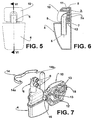
Figure 5 illustrates, schematically, a rear view of the suction muffler mounted in the cylinder head, according to the present invention; -
Figure 6 illustrates, schematically, a longitudinal sectional view of the suction muffler-cylinder head assembly, according to the line VI-VI shown infigure 5 ; and -
Figure 7 illustrates, schematically and in exploded front perspective view, the suction muffler and cylinder head, constructed according to the present invention. - The present invention will be described in relation to a compressor of a refrigeration system which, though not illustrated, comprises inside a shell, such as a hermetic shell, a motor-compressor assembly having a cylinder block within which is defined a cylinder which lodges, at one end, a piston, and has an opposite end closed by a
cylinder head 1 defining adischarge chamber 2 therewithin in selective fluid communication with a compression chamber (not illustrated) defined in the inside of the cylinder between a top portion of the piston and avalve plate 3 provided between the opposite end of the cylinder and thecylinder head 1. - The
valve plate 3 is provided with at least onesuction orifice 3a and with a discharge orifice (not illustrated) which are selectively and respectively closed by suction and discharge valves (not illustrated), eachsuction orifice 3a allowing the selective fluid communication between thedischarge chamber 2 and the compression chamber of the cylinder. The suction system being described further comprises asuction muffler 4, generally made in a material of low thermal conductibility, having a hollow body provided with a gas inlet (not illustrated) in fluid communication with the gas supplied to the compressor, and carrying anoutlet tube 5 in fluid communication with a suction side of the compressor, saidoutlet tube 5 presenting anend 6 internal to the hollow body and afree end 7 outwardly projecting from the hollow body and seated on thevalve plate 3 in coaxial alignment with arespective suction orifice 3a. According to a constructive form of the prior art suction system illustrated infigures 1 and 2 , theoutlet tube 5 is mounted to thecylinder head 1 so as to have itsfree end 7 mounted through thecylinder head 1. Although in said solution thecylinder head 1 presents a strong construction, this solution presents the disadvantages discussed above. - According to another constructive form illustrated in
figures 3 and 4 , theoutlet tube 5 has itsfree end 7 seated on thevalve plate 3 external to thecylinder head 1. In this construction, thecylinder head 1 is shaped in such a way that theoutlet tube 5 need not penetrate into the internal volume of saidcylinder head 1, minimizing the heating of the gas being drawn. However, said solution presents acylinder head 1 with a less strong construction and with the previously mentioned disadvantages. - The system of the present invention comprises a
cylinder head 10 provided, externally to itsdischarge chamber 11, with a reinforcingwall portion 12 which is dimensioned to define an increase in the structural rigidity of saidcylinder head 10, said reinforcingwall portion 12 having at least part of its extension spaced from theoutlet tube 5 in order to minimize the heat transfer from thecylinder head 10 to the gas being drawn through theoutlet tube 5. In a constructive option of the present invention, thereinforcing wall portion 12 occupies the area of thecylinder head 10 external to thedischarge chamber 11. The construction of the cylinder head of the present invention aims at maintaining the advantages presented by the prior art constructions illustrated infigures 1-4 , without the deficiencies thereof. Thecylinder head 10 of the present invention is constructed so as not to have a section presenting a through passage, such as that of the prior art illustrated infigure 3 , i.e., maintaining a structural rigidity which is greater than that presented by said prior art construction and similar to that of the construction illustrated infigure 1 . Since the sealing of the junction of thedischarge chamber 11 to thevalve plate 5 occurs on agasket 8, the construction of the present invention does not require the inclusion of additional sealing and fixation elements found in the prior art construction illustrated infigure 1 . - In a constructive option of the present invention, the
reinforcing wall portion 12 maintains theoutlet tube 5 seated on thevalve plate 3, said reinforcingwall portion 12 being for example also seated on thevalve plate 3. In a variant of this solution, thereinforcing wall portion 12 is medianly opened so as to involve and retain thefree end 7 of theoutlet tube 5, which trespasses said opened portion, to be seated on thevalve plate 3, or also to allow thefree end 7 of theoutlet tube 5 to be fitted into at least part of the extension of arespective suction orifice 3a in thevalve plate 3. - In the illustrated solution, the
free end 7 of theoutlet tube 5 is provided with twotubular projections 9, which are parallel and for example axially spaced from each other and each aligned with arespective suction orifice 3a of thevalve plate 3. - In this construction, the
cylinder head 10 is provided in the region of thereinforcing wall portion 12 with a pair ofopenings 13 which are parallel to each other, so that each receives atubular projection 9 of theoutlet tube 5, saidopenings 13 having their contour seated against thevalve plate 3. - The
tubular projections 9 provide the necessary thermal insulation between the cold gas and the adjacent warmest section represented by thecylinder head 1, besides representing an additional acoustic dampening in case any leakage occurs between the suction muffler and thegasket 8, which makes this construction acoustically stronger than that of the prior art illustrated infigure 3 . Thesetubular projections 9 can, for example, project farther than as shown herein and have an additional extension to cover part or the whole thickness of thevalve plate 3, providing an additional thermal insulation to another warm part of the compressor. With this construction, the temperature to which the interior of the suction muffler is submitted becomes similar to that presented by the solution offigure 3 , allowing the use of plastic material to construct its body, which simplifies the manufacturing and mounting process in relation to the prior art solution illustrated infigure 1 . - In another constructive option, not illustrated, the reinforcing
wall portion 12 is trespassed by theoutlet tube 5 in a portion thereof spaced from thevalve plate 3. - According to the present invention, there is further provided a
fixation element 14, for example in the form of a spring which surrounds theoutlet tube 5 mounted in thecylinder head 10, said fixation element having a pair of retainingend portions 14a, each fitted into a fitting receivingportion 15 defined in thecylinder head 10, for example in lateral portions thereof, said fitting receivingportions 15 being aligned to each other and orthogonal to the alignment of theopenings 13 of saidcylinder head 10. - The
fixation element 14, in this construction, has its movements restricted by thetubular projections 9 in axes that are orthogonal to each other and parallel to thevalve plate 3, said spring restricting the movement of the suction muffler in the directions parallel to thevalve plate 3, i.e., only in the directions in which the spring has some actuation. - The
fixation element 14 exerts on the suction muffler 4 a friction force in a direction parallel to the outlet tube and to thevalve plate 3 and, in the other directions, the force occurs by the rigidity of thefixation element 14. Additionally, eventual deformations caused to thecylinder head 10 by action of thefixation element 14 occur so as to better seal the region of thegasket 8 that is more susceptible to leakages and rupture, in this case the portion between thetubular projections 9. - While a construction for fixation means has been illustrated, it should be understood that other constructions are possible, such as a spring element, which can be affixed to the regions of the cylinder head adjacent to the
outlet tube 5 through fixation means, such as adhesive, screws, etc., which aspect should not be considered as a limitation for the inventive concept presented herein.
Claims (10)
- A suction system for a refrigeration compressor of the type which comprises a cylinder; a valve plate (3) which is provided with at least one suction orifice (3a), selectively closed by a suction valve, and which closes a cylinder end; a cylinder head (1,10) mounted against a face of the valve plate (3) opposite to that closing the cylinder and which defines a discharge chamber (2, 11) occupying part of said cylinder head (1, 10) and partially contouring the suction orifice (3a); and a suction muffler (4) comprising a hollow body having an outlet tube (5) projecting therefrom and presenting a free end (7) seated on the valve plate (3) in coaxial alignment with a respective suction orifice (3a), said cylinder head (10) being provided, externally to the discharge chamber (11), with a reinforcing wall portion (12) which is dimensioned to define an increase in the structural rigidity of the cylinder head (10), characterized in that the free end (7) of the outlet tube (5) is provided with two tubular projections (9) which are parallel to each other, each being aligned with a respective suction orifice (3a) of the valve plate (3).
- The system as set forth in claim 1, characterized in that the reinforcing wall portion (12) has at least part of its extension spaced from the outlet tube (5).
- The system as set forth in claim 2, characterized in that the reinforcing wall portion (12) maintains the outlet tube (5) seated on the valve plate (3).
- The system as set forth in claim 3, characterized in that the reinforcing wall portion (12) is trespassed by the outlet tube (5).
- The system as set forth in claim 3, characterized in that the reinforcing wall portion (12) is seated against the valve plate (3).
- The system as set forth in claim 5, characterized in that the reinforcing wall portion (12) occupies the area of the cylinder head (10) external to the discharge chamber (11).
- The system as set forth in claim 6, characterized in that the reinforcing wall portion (12) is medianly opened so as to surround and retain the free end (7) of the outlet tube (5).
- The system as set forth in claim 1, characterized in that the free end (7) of the outlet tube (5) is fitted into the interior of at least part of the extension of a respective suction orifice (3a) in the valve plate (3).
- The system as set forth in claim 1, characterized in that the cylinder head (10) comprises a pair of openings (13) which are parallel to each other, each receiving a respective tubular projection (9) of the outlet tube (5).
- The system as set forth in claim 1, characterized in that it comprises a fixation element (14) constantly forcing the cylinder head (10) against the valve plate (3).
Applications Claiming Priority (2)
| Application Number | Priority Date | Filing Date | Title |
|---|---|---|---|
| BR0400624-0A BRPI0400624A (en) | 2004-02-04 | 2004-02-04 | Refrigeration compressor suction system |
| PCT/BR2005/000014 WO2005075828A1 (en) | 2004-02-04 | 2005-02-01 | Suction system for a refrigeration compressor |
Publications (2)
| Publication Number | Publication Date |
|---|---|
| EP1711710A1 EP1711710A1 (en) | 2006-10-18 |
| EP1711710B1 true EP1711710B1 (en) | 2016-06-15 |
Family
ID=37722607
Family Applications (1)
| Application Number | Title | Priority Date | Filing Date |
|---|---|---|---|
| EP05700236.2A Not-in-force EP1711710B1 (en) | 2004-02-04 | 2005-02-01 | Suction system for a refrigeration compressor |
Country Status (8)
| Country | Link |
|---|---|
| US (1) | US7959416B2 (en) |
| EP (1) | EP1711710B1 (en) |
| JP (2) | JP4990633B2 (en) |
| KR (1) | KR101187001B1 (en) |
| CN (1) | CN100447414C (en) |
| BR (1) | BRPI0400624A (en) |
| ES (1) | ES2577513T3 (en) |
| WO (1) | WO2005075828A1 (en) |
Families Citing this family (7)
| Publication number | Priority date | Publication date | Assignee | Title |
|---|---|---|---|---|
| BRPI0801086A2 (en) * | 2008-03-31 | 2009-11-17 | Whirlpool Sa | refrigeration compressor electric power cable mounting arrangement |
| BRPI1103315B8 (en) * | 2011-07-29 | 2021-09-21 | Embraco Ind De Compressores E Solucoes Em Refrigeracao Ltda | suction chamber |
| BRPI1105384B1 (en) | 2011-12-20 | 2021-08-24 | Embraco Indústria De Compressores E Soluções Em Refrigeração Ltda | ALTERNATIVE COMPRESSOR CYLINDER COVER |
| BR202013024030Y1 (en) | 2013-09-19 | 2019-10-01 | Embraco Indústria De Compressores E Soluções E Refrigeração Ltda. | CONSTRUCTIVE ARRANGEMENT INTRODUCED IN HERMETIC COMPRESSOR ACOUSTIC FILTER |
| US10711777B2 (en) * | 2015-03-19 | 2020-07-14 | Embraco Industria De Compressores E Solucoes Em Refrigeracao Ltda | Suction acoustic filter for compressor |
| EP3998402B1 (en) * | 2019-07-12 | 2023-10-04 | Nidec Global Appliance Brasil Ltda. | Reciprocating compressor |
| KR20240067685A (en) * | 2022-11-09 | 2024-05-17 | 삼성전자주식회사 | Muffler for compressor |
Family Cites Families (19)
| Publication number | Priority date | Publication date | Assignee | Title |
|---|---|---|---|---|
| IT1172782B (en) * | 1983-12-12 | 1987-06-18 | Necchi Spa | SILENCER FOR MOTOR-COMPRESSORS |
| JPS635187A (en) * | 1986-06-23 | 1988-01-11 | Matsushita Refrig Co | Closed motor compressor |
| JPS643276A (en) * | 1987-06-26 | 1989-01-09 | Matsushita Refrigeration | Closed type motor-driven compressor |
| JP2624258B2 (en) * | 1987-06-26 | 1997-06-25 | 松下冷機株式会社 | Compressor silencer |
| JPS6460784A (en) | 1987-08-28 | 1989-03-07 | Matsushita Refrigeration | Enclosed motor compressor |
| JPS6480781A (en) * | 1987-09-21 | 1989-03-27 | Matsushita Refrigeration | Enclosed type motor-driven compressor |
| JPH0599141A (en) * | 1991-10-02 | 1993-04-20 | Matsushita Refrig Co Ltd | Closed type motor-operated compressor |
| KR200141490Y1 (en) * | 1993-04-24 | 1999-05-15 | 김광호 | Noise-reducing apparatus of a compressor |
| JPH07208334A (en) * | 1994-01-24 | 1995-08-08 | Matsushita Refrig Co Ltd | Enclosed type compressor |
| KR0143182B1 (en) * | 1994-04-29 | 1998-08-01 | 김광호 | Compressor |
| KR0143142B1 (en) * | 1995-03-07 | 1998-08-01 | 김광호 | Cylinder apparatus for on reciprocating canpressor |
| KR0156720B1 (en) * | 1995-07-27 | 1999-03-20 | 김광호 | Reciprocating compressor |
| KR0175891B1 (en) * | 1995-07-29 | 1999-10-01 | 윤종용 | compressor |
| JP3301895B2 (en) * | 1995-09-05 | 2002-07-15 | 三洋電機株式会社 | Hermetic compressor |
| KR19980027501U (en) * | 1996-11-16 | 1998-08-05 | 박병재 | Fuel tank structure of car |
| KR100207792B1 (en) * | 1997-02-24 | 1999-07-15 | 윤종용 | A close typed compressor |
| JP3776025B2 (en) * | 2000-11-29 | 2006-05-17 | 松下冷機株式会社 | Hermetic compressor |
| US6558137B2 (en) * | 2000-12-01 | 2003-05-06 | Tecumseh Products Company | Reciprocating piston compressor having improved noise attenuation |
| JP4872175B2 (en) * | 2001-08-28 | 2012-02-08 | パナソニック株式会社 | Hermetic electric compressor |
-
2004
- 2004-02-04 BR BR0400624-0A patent/BRPI0400624A/en not_active IP Right Cessation
-
2005
- 2005-02-01 ES ES05700236.2T patent/ES2577513T3/en active Active
- 2005-02-01 JP JP2006551690A patent/JP4990633B2/en not_active Expired - Fee Related
- 2005-02-01 CN CNB2005800040614A patent/CN100447414C/en not_active Expired - Fee Related
- 2005-02-01 WO PCT/BR2005/000014 patent/WO2005075828A1/en active Application Filing
- 2005-02-01 EP EP05700236.2A patent/EP1711710B1/en not_active Not-in-force
- 2005-02-01 KR KR1020067015890A patent/KR101187001B1/en not_active IP Right Cessation
- 2005-02-01 US US10/597,469 patent/US7959416B2/en active Active
-
2012
- 2012-02-24 JP JP2012038321A patent/JP2012137088A/en not_active Withdrawn
Also Published As
| Publication number | Publication date |
|---|---|
| US20080159881A1 (en) | 2008-07-03 |
| EP1711710A1 (en) | 2006-10-18 |
| CN1914422A (en) | 2007-02-14 |
| BRPI0400624A (en) | 2005-09-27 |
| JP4990633B2 (en) | 2012-08-01 |
| JP2007520660A (en) | 2007-07-26 |
| US7959416B2 (en) | 2011-06-14 |
| WO2005075828A1 (en) | 2005-08-18 |
| ES2577513T3 (en) | 2016-07-15 |
| CN100447414C (en) | 2008-12-31 |
| KR20060132897A (en) | 2006-12-22 |
| JP2012137088A (en) | 2012-07-19 |
| KR101187001B1 (en) | 2012-09-28 |
Similar Documents
| Publication | Publication Date | Title |
|---|---|---|
| EP1711710B1 (en) | Suction system for a refrigeration compressor | |
| US20050031461A1 (en) | Suction muffler for a reciprocating hermetic compressor | |
| EP0856106B1 (en) | A suction muffler for a hermetic compressor | |
| EP3779192B1 (en) | Silencer, compressor assembly and refrigerator | |
| US20090038329A1 (en) | Suction muffler for a refrigeration compressor | |
| EP2329146B1 (en) | Suction arrangement for a hermetic refrigeration compressor | |
| JP6225191B2 (en) | Insulation system for refrigeration compressor gas exhaust | |
| KR20110013444A (en) | Discharge valve arrangement for a hermetic compressor | |
| US7147082B2 (en) | Suction muffler for a reciprocating hermetic compressor | |
| US6536475B2 (en) | Fluid selector valve | |
| KR100778179B1 (en) | Economizer chamber for minimizing pressure pulsations | |
| JP4888754B2 (en) | Valve unit for hermetic compressor | |
| US7500540B2 (en) | Suction muffler for a hermetic compressor | |
| EP0561383B1 (en) | A refrigeration compressor | |
| WO2017191229A1 (en) | A hermetic compressor with increased performance | |
| EP4080051B1 (en) | Reciprocating compressor cylinder cover | |
| JP2001055976A (en) | Hermetically closed type compressor | |
| KR900009048Y1 (en) | Muffler for hermetic compressor | |
| JP2001304118A (en) | Hermetic compressor |
Legal Events
| Date | Code | Title | Description |
|---|---|---|---|
| PUAI | Public reference made under article 153(3) epc to a published international application that has entered the european phase |
Free format text: ORIGINAL CODE: 0009012 |
|
| 17P | Request for examination filed |
Effective date: 20060728 |
|
| AK | Designated contracting states |
Kind code of ref document: A1 Designated state(s): AT DE ES FR IT |
|
| DAX | Request for extension of the european patent (deleted) | ||
| RBV | Designated contracting states (corrected) |
Designated state(s): AT DE ES FR IT |
|
| RAP1 | Party data changed (applicant data changed or rights of an application transferred) |
Owner name: WHIRLPOOL S.A. |
|
| REG | Reference to a national code |
Ref country code: DE Ref legal event code: R079 Ref document number: 602005049522 Country of ref document: DE Free format text: PREVIOUS MAIN CLASS: F04B0039000000 Ipc: F04B0039120000 |
|
| GRAP | Despatch of communication of intention to grant a patent |
Free format text: ORIGINAL CODE: EPIDOSNIGR1 |
|
| RIC1 | Information provided on ipc code assigned before grant |
Ipc: F04B 39/00 20060101ALI20151109BHEP Ipc: F04B 39/12 20060101AFI20151109BHEP |
|
| INTG | Intention to grant announced |
Effective date: 20151201 |
|
| GRAS | Grant fee paid |
Free format text: ORIGINAL CODE: EPIDOSNIGR3 |
|
| GRAA | (expected) grant |
Free format text: ORIGINAL CODE: 0009210 |
|
| AK | Designated contracting states |
Kind code of ref document: B1 Designated state(s): AT DE ES FR IT |
|
| REG | Reference to a national code |
Ref country code: AT Ref legal event code: REF Ref document number: 806654 Country of ref document: AT Kind code of ref document: T Effective date: 20160715 Ref country code: ES Ref legal event code: FG2A Ref document number: 2577513 Country of ref document: ES Kind code of ref document: T3 Effective date: 20160715 |
|
| REG | Reference to a national code |
Ref country code: DE Ref legal event code: R096 Ref document number: 602005049522 Country of ref document: DE |
|
| REG | Reference to a national code |
Ref country code: FR Ref legal event code: PLFP Year of fee payment: 13 |
|
| REG | Reference to a national code |
Ref country code: DE Ref legal event code: R097 Ref document number: 602005049522 Country of ref document: DE |
|
| PLBE | No opposition filed within time limit |
Free format text: ORIGINAL CODE: 0009261 |
|
| STAA | Information on the status of an ep patent application or granted ep patent |
Free format text: STATUS: NO OPPOSITION FILED WITHIN TIME LIMIT |
|
| 26N | No opposition filed |
Effective date: 20170316 |
|
| REG | Reference to a national code |
Ref country code: FR Ref legal event code: PLFP Year of fee payment: 14 |
|
| REG | Reference to a national code |
Ref country code: AT Ref legal event code: MM01 Ref document number: 806654 Country of ref document: AT Kind code of ref document: T Effective date: 20170201 |
|
| PG25 | Lapsed in a contracting state [announced via postgrant information from national office to epo] |
Ref country code: AT Free format text: LAPSE BECAUSE OF NON-PAYMENT OF DUE FEES Effective date: 20170201 |
|
| REG | Reference to a national code |
Ref country code: ES Ref legal event code: PC2A Owner name: EMBRACO INDUSTRIA DE COMPRESSORES E SOLUSOES EM RE Effective date: 20190227 |
|
| REG | Reference to a national code |
Ref country code: AT Ref legal event code: UEP Ref document number: 806654 Country of ref document: AT Kind code of ref document: T Effective date: 20160615 |
|
| PGFP | Annual fee paid to national office [announced via postgrant information from national office to epo] |
Ref country code: FR Payment date: 20210224 Year of fee payment: 17 |
|
| REG | Reference to a national code |
Ref country code: DE Ref legal event code: R082 Ref document number: 602005049522 Country of ref document: DE Representative=s name: SCHIEBER - FARAGO PATENTANWAELTE, DE Ref country code: DE Ref legal event code: R082 Ref document number: 602005049522 Country of ref document: DE Representative=s name: SCHIEBER FARAGO PATENTANWAELTE, DE |
|
| PGFP | Annual fee paid to national office [announced via postgrant information from national office to epo] |
Ref country code: DE Payment date: 20220217 Year of fee payment: 18 |
|
| PGFP | Annual fee paid to national office [announced via postgrant information from national office to epo] |
Ref country code: IT Payment date: 20220218 Year of fee payment: 18 |
|
| PGFP | Annual fee paid to national office [announced via postgrant information from national office to epo] |
Ref country code: ES Payment date: 20220426 Year of fee payment: 18 |
|
| PG25 | Lapsed in a contracting state [announced via postgrant information from national office to epo] |
Ref country code: FR Free format text: LAPSE BECAUSE OF NON-PAYMENT OF DUE FEES Effective date: 20220228 |
|
| REG | Reference to a national code |
Ref country code: DE Ref legal event code: R119 Ref document number: 602005049522 Country of ref document: DE |
|
| PG25 | Lapsed in a contracting state [announced via postgrant information from national office to epo] |
Ref country code: IT Free format text: LAPSE BECAUSE OF NON-PAYMENT OF DUE FEES Effective date: 20230201 Ref country code: DE Free format text: LAPSE BECAUSE OF NON-PAYMENT OF DUE FEES Effective date: 20230901 |
|
| REG | Reference to a national code |
Ref country code: ES Ref legal event code: FD2A Effective date: 20240402 |
|
| PG25 | Lapsed in a contracting state [announced via postgrant information from national office to epo] |
Ref country code: ES Free format text: LAPSE BECAUSE OF NON-PAYMENT OF DUE FEES Effective date: 20230202 |
|
| PG25 | Lapsed in a contracting state [announced via postgrant information from national office to epo] |
Ref country code: ES Free format text: LAPSE BECAUSE OF NON-PAYMENT OF DUE FEES Effective date: 20230202 |