WO2017191229A1 - A hermetic compressor with increased performance - Google Patents
A hermetic compressor with increased performance Download PDFInfo
- Publication number
- WO2017191229A1 WO2017191229A1 PCT/EP2017/060601 EP2017060601W WO2017191229A1 WO 2017191229 A1 WO2017191229 A1 WO 2017191229A1 EP 2017060601 W EP2017060601 W EP 2017060601W WO 2017191229 A1 WO2017191229 A1 WO 2017191229A1
- Authority
- WO
- WIPO (PCT)
- Prior art keywords
- valve
- refrigerant
- exhaust
- disposed
- suction
- Prior art date
Links
Images


Classifications
-
- F—MECHANICAL ENGINEERING; LIGHTING; HEATING; WEAPONS; BLASTING
- F04—POSITIVE - DISPLACEMENT MACHINES FOR LIQUIDS; PUMPS FOR LIQUIDS OR ELASTIC FLUIDS
- F04B—POSITIVE-DISPLACEMENT MACHINES FOR LIQUIDS; PUMPS
- F04B39/00—Component parts, details, or accessories, of pumps or pumping systems specially adapted for elastic fluids, not otherwise provided for in, or of interest apart from, groups F04B25/00 - F04B37/00
- F04B39/10—Adaptations or arrangements of distribution members
- F04B39/1066—Valve plates
-
- F—MECHANICAL ENGINEERING; LIGHTING; HEATING; WEAPONS; BLASTING
- F04—POSITIVE - DISPLACEMENT MACHINES FOR LIQUIDS; PUMPS FOR LIQUIDS OR ELASTIC FLUIDS
- F04B—POSITIVE-DISPLACEMENT MACHINES FOR LIQUIDS; PUMPS
- F04B39/00—Component parts, details, or accessories, of pumps or pumping systems specially adapted for elastic fluids, not otherwise provided for in, or of interest apart from, groups F04B25/00 - F04B37/00
- F04B39/0027—Pulsation and noise damping means
- F04B39/0055—Pulsation and noise damping means with a special shape of fluid passage, e.g. bends, throttles, diameter changes, pipes
- F04B39/0061—Pulsation and noise damping means with a special shape of fluid passage, e.g. bends, throttles, diameter changes, pipes using muffler volumes
-
- F—MECHANICAL ENGINEERING; LIGHTING; HEATING; WEAPONS; BLASTING
- F04—POSITIVE - DISPLACEMENT MACHINES FOR LIQUIDS; PUMPS FOR LIQUIDS OR ELASTIC FLUIDS
- F04B—POSITIVE-DISPLACEMENT MACHINES FOR LIQUIDS; PUMPS
- F04B39/00—Component parts, details, or accessories, of pumps or pumping systems specially adapted for elastic fluids, not otherwise provided for in, or of interest apart from, groups F04B25/00 - F04B37/00
- F04B39/06—Cooling; Heating; Prevention of freezing
-
- F—MECHANICAL ENGINEERING; LIGHTING; HEATING; WEAPONS; BLASTING
- F04—POSITIVE - DISPLACEMENT MACHINES FOR LIQUIDS; PUMPS FOR LIQUIDS OR ELASTIC FLUIDS
- F04B—POSITIVE-DISPLACEMENT MACHINES FOR LIQUIDS; PUMPS
- F04B39/00—Component parts, details, or accessories, of pumps or pumping systems specially adapted for elastic fluids, not otherwise provided for in, or of interest apart from, groups F04B25/00 - F04B37/00
- F04B39/12—Casings; Cylinders; Cylinder heads; Fluid connections
- F04B39/123—Fluid connections
-
- F—MECHANICAL ENGINEERING; LIGHTING; HEATING; WEAPONS; BLASTING
- F04—POSITIVE - DISPLACEMENT MACHINES FOR LIQUIDS; PUMPS FOR LIQUIDS OR ELASTIC FLUIDS
- F04B—POSITIVE-DISPLACEMENT MACHINES FOR LIQUIDS; PUMPS
- F04B39/00—Component parts, details, or accessories, of pumps or pumping systems specially adapted for elastic fluids, not otherwise provided for in, or of interest apart from, groups F04B25/00 - F04B37/00
- F04B39/12—Casings; Cylinders; Cylinder heads; Fluid connections
- F04B39/125—Cylinder heads
-
- F—MECHANICAL ENGINEERING; LIGHTING; HEATING; WEAPONS; BLASTING
- F04—POSITIVE - DISPLACEMENT MACHINES FOR LIQUIDS; PUMPS FOR LIQUIDS OR ELASTIC FLUIDS
- F04B—POSITIVE-DISPLACEMENT MACHINES FOR LIQUIDS; PUMPS
- F04B39/00—Component parts, details, or accessories, of pumps or pumping systems specially adapted for elastic fluids, not otherwise provided for in, or of interest apart from, groups F04B25/00 - F04B37/00
- F04B39/14—Provisions for readily assembling or disassembling
-
- F—MECHANICAL ENGINEERING; LIGHTING; HEATING; WEAPONS; BLASTING
- F04—POSITIVE - DISPLACEMENT MACHINES FOR LIQUIDS; PUMPS FOR LIQUIDS OR ELASTIC FLUIDS
- F04B—POSITIVE-DISPLACEMENT MACHINES FOR LIQUIDS; PUMPS
- F04B53/00—Component parts, details or accessories not provided for in, or of interest apart from, groups F04B1/00 - F04B23/00 or F04B39/00 - F04B47/00
- F04B53/10—Valves; Arrangement of valves
- F04B53/1085—Valves; Arrangement of valves having means for limiting the opening height
Definitions
- the present invention relates to a hermetic compressor suitable for use in cooling devices.
- hermetic compressors In hermetic compressors, a significant part of the losses in the course of transmission of the refrigerant gas to the refrigeration cycle occurs when the refrigerant gas is compressed in the cylinder and transmitted through the opened exhaust valve to the exhaust volume of the cylinder head.
- hermetic compressor (1') in the compressing movement of the piston in the cylinder, the refrigerant gas passes through the exhaust port on the valve table and fills into the exhaust chamber (23') in the cylinder head (22') and is sent therefrom to the refrigeration cycle.
- the opening movement of the exhaust valve (9') is limited by means of a stopper (24') on the valve table (5') ( Figure 2).
- the exhaust valve (9') opens to the extent permitted by the stopper (24') and thus, the desired amount of refrigerant gas pressure is provided in the exhaust chamber (23'). Circulation of the refrigerant at high temperature and pressure in the exhaust chamber (23') causes the temperature of the cylinder head (22') to excessively rise. Heat transfer occurs from the high temperature cylinder head (22') to the refrigerant gas circulating through the suction plenum (18'), the cylinder block and the compressor (1'), increasing the temperature of the said regions in an undesired manner, and adversely affecting the performance of the compressor.
- a valve unit used in a hermetic compressor is disclosed.
- the movement of the exhaust valve is restricted by means of a stopper mounted on the valve table.
- the aim of the present invention is the realization of a compressor the performance of which is improved by preventing the temperature of the refrigerant that is pumped into the refrigeration cycle from increasing in the exhaust region.
- the refrigerant sucked from the refrigeration cycle into the cylinder and pumped from the cylinder into the refrigeration cycle is guided by means of a valve table.
- the valve table comprises thereon suction (inlet) and exhaust (outlet) ports that enable the refrigerant to enter and exit, and an exhaust pass port connected to an exhaust muffler.
- the compressor of the present invention comprises a counter table joined flush with the valve table, that enables the refrigerant sucked from the refrigeration cycle during the suction movement of the piston to be guided to the inlet port and enables the refrigerant passing through the outlet port during the pumping movement of the piston to be guided directly to the exhaust pass port.
- the metal component comprising an exhaust chamber therein and known as the "cylinder head" in the prior art is not used.
- the counter table with a thickness of a few millimeters that is produced from plastic and coupled with the valve table performs the function of the metal component known as the "cylinder head".
- the counter table occupies a much smaller space than the cylinder head and provides the solving of the problem of temperature increase in the exhaust region.
- the counter table comprises a guiding recess that enables the refrigerant to be guided from the outlet port to the exhaust pass port.
- the guiding recess performs a function that is similar to that of the "exhaust chamber" in the cylinder head in the prior art; however, since the refrigerant is guided directly to the exhaust pass port, the guiding recess does not heat up as much as the exhaust chamber.
- the counter table comprises a pressing protrusion that enables the exhaust valve to be fastened by pressing the same on the valve table, thus eliminating the need for using items such as rivet, etc. to fasten the exhaust valve to the valve table.
- the counter table comprises a restriction surface that enables the refrigerant gas to be guided to the exhaust pass port at the desired pressure by restricting the movement of the exhaust valve.
- the restriction surface is formed by shaping the counter table and the need for using a separate stopper for the exhaust valve is eliminated.
- the compressor comprises a suction plenum that extends from the suction muffler toward the counter table and that enables the refrigerant to be delivered from the suction muffler to the valve table and the cylinder, and the suction plenum is connected to the counter table by adhesion or vibration welding or produced as a single piece with the counter table.
- the counter table comprises a suction plenum housing that receives the suction plenum and that enables the suction plenum to exert pressure on the valve table.
- the counter table comprises a sealing barrier that prevents the refrigerant from leaking into the inner environment of the casing.
- the counter table is not affected from the high temperature of the refrigerant in gas state and the heat transfer to the valve table and the body of the compressor, also called the cylinder block, is reduced.
- the temperature of the refrigerant take into the cylinder during the suction process is decreased while the mass flow of the refrigerant is increased, thus improving the refrigeration efficiency of the compressor.
- Figure 1 – is the cross-sectional view of a compressor in the prior art.
- Figure 2 - is the perspective view of a valve table and a stopper for restricting the movement of the exhaust valve in the prior art.
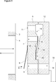
- Figure 3 - is the cross-sectional view of the compressor of the present invention.
- Figure 4 - is the schematic view of a valve table and a counter table in a separated manner.
- Figure 5 - is the schematic view of a valve table and a counter table in the coupled state.
- Figure 6 - is the perspective view of a valve table.
- Figure 7 — is the perspective view of a counter table.
- Figure 8 — is the perspective view of the counter table in an embodiment of the present invention.
- Figure 9 – is the perspective view of the counter table from a different angle.
- Figure 10 - is the perspective view of the counter table comprising the sealing barrier.
- the hermetic compressor (1) suitable for use for circulation of a refrigerant in the refrigeration cycle (not shown in the figures) in cooling devices, for example in refrigerators, comprises a casing (2); a cylinder (3) that is disposed in the casing (2) and that enables the refrigerant to be sucked and pumped; a piston (4) that is operated in the cylinder (3); a valve table (5) that enables the refrigerant sucked and pumped into the cylinder (3) through the movement of the piston (4); an inlet port (6) that is disposed on the valve table (5) and that enables the refrigerant to enter the cylinder (3) during the suction movement of the piston (4); an outlet port (7) that is disposed on the valve table (5) and that enables the refrigerant to be discharged from the cylinder (3) during the pumping movement of the piston (4); a suction valve (8) that opens and closes the inlet port (6) and an exhaust valve (9) that opens and closes the outlet port (7), the suction valve (8) and
- the compressor (1) of the present invention comprises a counter table (12)
- the piston (4) When the piston (4) performs the suction movement in the cylinder (3), the refrigerant received from the refrigeration cycle is guided to the inlet port (6) of the valve table (5) by means of the counter table (12).
- the details related to the suction of the refrigerant are given in the following paragraphs and in Claims 5 and 7.
- the exhaust valve (9) opens the outlet port (7) and enables the refrigerant to pass between the valve table (5) and the counter table (12) so as to be directly guided to the exhaust pass port (11).
- the refrigerant is transmitted from the exhaust pass port (13) to the exhaust muffler (12) through a channel and therefrom to the refrigeration cycle.
- the counter table (12) performs the function of the component known as the "cylinder head" that enables the sucked and pumped refrigerant to be guided in the state of the art.
- the compressor (1) comprises two flow guiding recesses (13) that are oppositely disposed on the adjacent surfaces of the counter table (12) and the valve table (5), that extend from the level of the outlet port (7) to the level of the exhaust pass port (11) and that enable the refrigerant to be guided from the outlet port (7) to the exhaust pass port (11) ( Figure 4, Figure 5, Figure 7).
- the valve table (5) comprises a bearing recess (14) that is disposed on the surface of the valve table (5) adjacent to the counter table (12), that enables the exhaust valve (9) to be borne as partially embedded into the valve table (5) perpendicularly to the plane of the valve table (5) so as to open and close over the outlet port (7) ( Figure 4, Figure 5).
- the counter table (12) comprises a pressing protrusion (15) that is disposed on the surface of the counter table (12) adjacent to the valve table (5), that extends toward the bearing recess (14) and that squeezes the part of the exhaust valve in the bearing recess (14) so as to enable the exhaust valve (9) to be fastened to the valve table (5).
- the counter table (12) is fastened to the cylinder (3) block together with the valve table (5) by means of bolts, and the pressing protrusion (15) fastens the exhaust valve (9) from one end thereof into the bearing recess (14) so that the exhaust valve (9) opens and closes on the outlet port (7).
- the counter table (12) comprises a restriction surface (16) that is disposed on the surface of the counter table (12) adjacent to the valve table (5), opposite to the exhaust valve (9), that extends from the pressing protrusion (15) toward the flow guiding recess (13) in an inclined manner, that enables the refrigerating gas to be guided to the exhaust pass port (11) at the desired pressure by restricting the movement of the exhaust valve (9) ( Figure 4, Figure 5, Figure 7).
- the restriction surface (16) is located on the part of the counter table (12) opposite to the exhaust valve (9). The exhaust valve (9) hits the restriction surface (16) when opened during the compression process in the cylinder (3).
- the restriction surface (16) is formed by shaping the counter table (12) and the need for using as separate stopper is eliminated.
- valve table (5) is produced from metal and the counter table (12) is produced from a material with low thermal transmission coefficient such as plastic, etc., and the thickness of the counter table (12) is almost equal to that of the metal valve table (5). Heat transfer to the refrigerant gas and hence to the cylinder (3) block is reduced.
- the compressor (1) comprises a suction muffler (17) that is produced from a plastic material and that provides the attenuation of the noise generated by the refrigerant received from the refrigeration cycle and sucked into the casing (2), and a suction plenum (18) that extends from the suction muffler (17) toward the counter table (12) and that enables the refrigerant to be delivered from the suction muffler (17) to the valve table (5) and the cylinder (3) ( Figure 3, Figure 4, Figure 5).
- the suction plenum (18) is also known as "muffler head" in the state of the art embodiments.
- the counter table (12) comprises a transition port (19) that is disposed between the suction plenum (18) and the inlet port (6) and that enables the refrigerant to be delivered from the suction plenum (18) to the inlet port (6) ( Figure 4, Figure 5, Figure 7).
- the suction plenum (18) is fastened to the counter table (12) by adhesion or vibration welding.
- the suction plenum (18) is produced as a single piece with the counter table (12).
- the counter table (12) comprises a suction plenum housing (20) that is produced as a single piece with the counter table (12), that receives the suction plenum (18), that enables the suction plenum (18) to exert pressure on the valve table (5) and thus prevents the refrigerant in hot gas state from being sucked from the internal environment of the casing ( Figure 8, Figure 9).
- the suction plenum (18) directly presses on the valve table (5) and delivers the refrigerant to the inlet port (6).
- the counter table (12) comprises at least one sealing barrier (21) that is disposed on the surface of the counter table (12) adjacent to the valve table (5) and that prevents the refrigerant from leaking into the internal environment of the casing (2) through the valve table (5) and the counter table (12) during the pumping movement in the cylinder (3) ( Figure 10).
- the need for the use of "cylinder head” used in the state of the art is eliminated and the counter plate (12) is used instead. Since no “exhaust chamber” is provided in the counter table (12), the production of the counter table (12) is low-cost and easier with respect to the "cylinder head", and the counter table (12) heats up less and occupies a lesser space than the cylinder head. The counter table (12) is not affected from the high temperature of the refrigerant in gas state (exhaust gas), and the heat transfer to the valve table (5) and the cylinder (3) block is reduced.
- the temperature of the cylinder (3) block is reduced, the mass flow rate of the refrigerant taken into the cylinder (3) is increased, the refrigeration coefficient of performance (COP) is increased, and hence the refrigeration performance is improved.
- the use of the component known as the "exhaust valve stopper”, that is used to restrict the movement of the exhaust valve (9) and that is externally mounted in the state of the art embodiments, is eliminated, thus the number of components is decreased and the ease of production is provided.
Abstract
The present invention relates to a hermetic compressor (1) suitable for use for circulation of a refrigerant fluid in a refrigeration cycle in cooling devices, for example in refrigerators, comprising a casing (2); a cylinder (3) that is disposed in the casing (2) and that enables the refrigerant to be sucked and pumped; a piston (4) that is operated in the cylinder (3); a valve table (5) that enables the refrigerant sucked and pumped into the cylinder (3) with the movement of the piston (4) to be guided; an exhaust muffler (10), and an exhaust pass port (11) that is disposed on the valve table (5).
Description
The present invention relates to a hermetic compressor suitable for use in cooling devices.
In hermetic compressors, a significant part of the losses in the course of transmission of the refrigerant gas to the refrigeration cycle occurs when the refrigerant gas is compressed in the cylinder and transmitted through the opened exhaust valve to the exhaust volume of the cylinder head. In a state of the art hermetic compressor (1'), in the compressing movement of the piston in the cylinder, the refrigerant gas passes through the exhaust port on the valve table and fills into the exhaust chamber (23') in the cylinder head (22') and is sent therefrom to the refrigeration cycle. The opening movement of the exhaust valve (9') is limited by means of a stopper (24') on the valve table (5') (Figure 2). During the compression of the gas in the cylinder, the exhaust valve (9') opens to the extent permitted by the stopper (24') and thus, the desired amount of refrigerant gas pressure is provided in the exhaust chamber (23'). Circulation of the refrigerant at high temperature and pressure in the exhaust chamber (23') causes the temperature of the cylinder head (22') to excessively rise. Heat transfer occurs from the high temperature cylinder head (22') to the refrigerant gas circulating through the suction plenum (18'), the cylinder block and the compressor (1'), increasing the temperature of the said regions in an undesired manner, and adversely affecting the performance of the compressor.
In the United States Patent No. US5209260 and the International Patent Application No. WO2015011906, a valve unit used in a hermetic compressor is disclosed. The movement of the exhaust valve is restricted by means of a stopper mounted on the valve table.
In the United States Patent No. US6641374, a cylinder head that is used in a hermetic compressor and composed of two sections is disclosed.
In the International Patent Application No. WO2012166051, a valve table with improved thermal insulation, that is disposed in a compressor is disclosed.
The aim of the present invention is the realization of a compressor the performance of which is improved by preventing the temperature of the refrigerant that is pumped into the refrigeration cycle from increasing in the exhaust region.
The compressor realized in order to attain the aim of the present invention is explicated in the claims.
In the hermetic compressor, the refrigerant sucked from the refrigeration cycle into the cylinder and pumped from the cylinder into the refrigeration cycle is guided by means of a valve table. The valve table comprises thereon suction (inlet) and exhaust (outlet) ports that enable the refrigerant to enter and exit, and an exhaust pass port connected to an exhaust muffler. The compressor of the present invention comprises a counter table joined flush with the valve table, that enables the refrigerant sucked from the refrigeration cycle during the suction movement of the piston to be guided to the inlet port and enables the refrigerant passing through the outlet port during the pumping movement of the piston to be guided directly to the exhaust pass port. In the embodiment of the present invention, the metal component comprising an exhaust chamber therein and known as the "cylinder head" in the prior art is not used. The counter table with a thickness of a few millimeters that is produced from plastic and coupled with the valve table performs the function of the metal component known as the "cylinder head". The counter table occupies a much smaller space than the cylinder head and provides the solving of the problem of temperature increase in the exhaust region.
In an embodiment of the present invention, the counter table comprises a guiding recess that enables the refrigerant to be guided from the outlet port to the exhaust pass port. The guiding recess performs a function that is similar to that of the "exhaust chamber" in the cylinder head in the prior art; however, since the refrigerant is guided directly to the exhaust pass port, the guiding recess does not heat up as much as the exhaust chamber.
In another embodiment of the present invention, the counter table comprises a pressing protrusion that enables the exhaust valve to be fastened by pressing the same on the valve table, thus eliminating the need for using items such as rivet, etc. to fasten the exhaust valve to the valve table.
In another embodiment of the present invention, the counter table comprises a restriction surface that enables the refrigerant gas to be guided to the exhaust pass port at the desired pressure by restricting the movement of the exhaust valve. The restriction surface is formed by shaping the counter table and the need for using a separate stopper for the exhaust valve is eliminated.
In an embodiment of the present invention, the compressor comprises a suction plenum that extends from the suction muffler toward the counter table and that enables the refrigerant to be delivered from the suction muffler to the valve table and the cylinder, and the suction plenum is connected to the counter table by adhesion or vibration welding or produced as a single piece with the counter table.
In another embodiment of the present invention, the counter table comprises a suction plenum housing that receives the suction plenum and that enables the suction plenum to exert pressure on the valve table.
In another embodiment of the present invention, the counter table comprises a sealing barrier that prevents the refrigerant from leaking into the inner environment of the casing.
In the compressor of the present invention, the counter table is not affected from the high temperature of the refrigerant in gas state and the heat transfer to the valve table and the body of the compressor, also called the cylinder block, is reduced. The temperature of the refrigerant take into the cylinder during the suction process is decreased while the mass flow of the refrigerant is increased, thus improving the refrigeration efficiency of the compressor.
The compressor realized in order to attain the aim of the present invention is illustrated in the attached figures, where:
Figure 1 – is the cross-sectional view of a compressor in the prior art.
Figure 2 - is the perspective view of a valve table and a stopper for restricting the movement of the exhaust valve in the prior art.
Figure 3 - is the cross-sectional view of the compressor of the present invention.
Figure 4 - is the schematic view of a valve table and a counter table in a separated manner.
Figure 5 - is the schematic view of a valve table and a counter table in the coupled state.
Figure 6 - is the perspective view of a valve table.
Figure 7 – is the perspective view of a counter table.
Figure 8 – is the perspective view of the counter table in an embodiment of the present invention.
Figure 9 – is the perspective view of the counter table from a different angle.
Figure 10 - is the perspective view of the counter table comprising the sealing barrier.
The elements illustrated in the figures are numbered as follows:
1. Compressor
2. Casing
3. Cylinder
4. Piston
5. Valve table
6. Inlet port
7. Outlet port
8. Suction valve
Exhaust valve
10. Exhaust muffler
11. Exhaust pass port
12. Counter table
13. Flow guiding recess
14. Bearing recess
15. Pressing protrusion
16. Restriction surface
17. Suction muffler
18. Suction plenum
19. Transition port
20. Suction plenum housing
21. Sealing barrier
1' A compressor in the prior art
5’. A valve table in the prior art
9' An exhaust table in the prior art
18'. A suction plenum in the prior art
22'. A cylinder head in the prior art
23'. An exhaust chamber in the prior art
24'. A stopper in the prior art
The hermetic compressor (1) suitable for use for circulation of a refrigerant in the refrigeration cycle (not shown in the figures) in cooling devices, for example in refrigerators, comprises a casing (2); a cylinder (3) that is disposed in the casing (2) and that enables the refrigerant to be sucked and pumped; a piston (4) that is operated in the cylinder (3); a valve table (5) that enables the refrigerant sucked and pumped into the cylinder (3) through the movement of the piston (4); an inlet port (6) that is disposed on the valve table (5) and that enables the refrigerant to enter the cylinder (3) during the suction movement of the piston (4); an outlet port (7) that is disposed on the valve table (5) and that enables the refrigerant to be discharged from the cylinder (3) during the pumping movement of the piston (4); a suction valve (8) that opens and closes the inlet port (6) and an exhaust valve (9) that opens and closes the outlet port (7), the suction valve (8) and the exhaust valve (9) being disposed on the valve table (5); an exhaust muffler (10) that has a hollow, closed volume and that provides the attenuation of the noise generated during the pumping of the refrigerant, and an exhaust pass port (11) that is disposed on the valve table (5), that enables the refrigerant to be delivered to the exhaust muffler (10) through a channel (not shown in the figures) and to be added therefrom to the refrigeration cycle.
The compressor (1) of the present invention comprises a counter table (12)
- that is coupled with the valve table (5),
- that forms, together with the valve table (5), a sandwich assembly between which the exhaust valve (9) is disposed,
- that enables the refrigerant sucked from the refrigeration cycle during the suction movement of the piston (4) to be guided to the inlet port (6), and
- that provides the refrigerant passing through the outlet port during the pumping movement of the piston (4) to be guided directly to the exhaust pass port (11)
(Figure 4, Figure 5, Figure 7).
When the piston (4) performs the suction movement in the cylinder (3), the refrigerant received from the refrigeration cycle is guided to the inlet port (6) of the valve table (5) by means of the counter table (12). The details related to the suction of the refrigerant are given in the following paragraphs and in Claims 5 and 7. When the piston (4) performs the compression movement in the cylinder (3), the exhaust valve (9) opens the outlet port (7) and enables the refrigerant to pass between the valve table (5) and the counter table (12) so as to be directly guided to the exhaust pass port (11). The refrigerant is transmitted from the exhaust pass port (13) to the exhaust muffler (12) through a channel and therefrom to the refrigeration cycle. The counter table (12) performs the function of the component known as the "cylinder head" that enables the sucked and pumped refrigerant to be guided in the state of the art.
In an embodiment of the present invention, the compressor (1) comprises two flow guiding recesses (13) that are oppositely disposed on the adjacent surfaces of the counter table (12) and the valve table (5), that extend from the level of the outlet port (7) to the level of the exhaust pass port (11) and that enable the refrigerant to be guided from the outlet port (7) to the exhaust pass port (11) (Figure 4, Figure 5, Figure 7).
In another embodiment of the present invention, the valve table (5) comprises a bearing recess (14) that is disposed on the surface of the valve table (5) adjacent to the counter table (12), that enables the exhaust valve (9) to be borne as partially embedded into the valve table (5) perpendicularly to the plane of the valve table (5) so as to open and close over the outlet port (7) (Figure 4, Figure 5).
In this embodiment, the counter table (12) comprises a pressing protrusion (15) that is disposed on the surface of the counter table (12) adjacent to the valve table (5), that extends toward the bearing recess (14) and that squeezes the part of the exhaust valve in the bearing recess (14) so as to enable the exhaust valve (9) to be fastened to the valve table (5). The counter table (12) is fastened to the cylinder (3) block together with the valve table (5) by means of bolts, and the pressing protrusion (15) fastens the exhaust valve (9) from one end thereof into the bearing recess (14) so that the exhaust valve (9) opens and closes on the outlet port (7). The need for the riveting process used in the state of the art embodiments to fasten the exhaust valve (9) to the valve table (5) is eliminated, thus decreasing the number of components used and providing ease of production.
In another embodiment of the present invention, the counter table (12) comprises a restriction surface (16) that is disposed on the surface of the counter table (12) adjacent to the valve table (5), opposite to the exhaust valve (9), that extends from the pressing protrusion (15) toward the flow guiding recess (13) in an inclined manner, that enables the refrigerating gas to be guided to the exhaust pass port (11) at the desired pressure by restricting the movement of the exhaust valve (9) (Figure 4, Figure 5, Figure 7). In this embodiment, the restriction surface (16) is located on the part of the counter table (12) opposite to the exhaust valve (9). The exhaust valve (9) hits the restriction surface (16) when opened during the compression process in the cylinder (3). In the compressor (1) of the present invention, the restriction surface (16) is formed by shaping the counter table (12) and the need for using as separate stopper is eliminated.
In another embodiment of the present invention, the valve table (5) is produced from metal and the counter table (12) is produced from a material with low thermal transmission coefficient such as plastic, etc., and the thickness of the counter table (12) is almost equal to that of the metal valve table (5). Heat transfer to the refrigerant gas and hence to the cylinder (3) block is reduced.
In an embodiment of the present invention, the compressor (1) comprises a suction muffler (17) that is produced from a plastic material and that provides the attenuation of the noise generated by the refrigerant received from the refrigeration cycle and sucked into the casing (2), and a suction plenum (18) that extends from the suction muffler (17) toward the counter table (12) and that enables the refrigerant to be delivered from the suction muffler (17) to the valve table (5) and the cylinder (3) (Figure 3, Figure 4, Figure 5). The suction plenum (18) is also known as "muffler head" in the state of the art embodiments.
In another embodiment of the present invention, the counter table (12) comprises a transition port (19) that is disposed between the suction plenum (18) and the inlet port (6) and that enables the refrigerant to be delivered from the suction plenum (18) to the inlet port (6) (Figure 4, Figure 5, Figure 7).
In another embodiment of the present invention, the suction plenum (18) is fastened to the counter table (12) by adhesion or vibration welding.
In another embodiment of the present invention, the suction plenum (18) is produced as a single piece with the counter table (12).
In another embodiment of the present invention, the counter table (12) comprises a suction plenum housing (20) that is produced as a single piece with the counter table (12), that receives the suction plenum (18), that enables the suction plenum (18) to exert pressure on the valve table (5) and thus prevents the refrigerant in hot gas state from being sucked from the internal environment of the casing (Figure 8, Figure 9). In this embodiment, the suction plenum (18) directly presses on the valve table (5) and delivers the refrigerant to the inlet port (6).
In another embodiment of the present invention, the counter table (12) comprises at least one sealing barrier (21) that is disposed on the surface of the counter table (12) adjacent to the valve table (5) and that prevents the refrigerant from leaking into the internal environment of the casing (2) through the valve table (5) and the counter table (12) during the pumping movement in the cylinder (3) (Figure 10).
In the compressor (1) of the present invention, the need for the use of "cylinder head" used in the state of the art is eliminated and the counter plate (12) is used instead. Since no "exhaust chamber" is provided in the counter table (12), the production of the counter table (12) is low-cost and easier with respect to the "cylinder head", and the counter table (12) heats up less and occupies a lesser space than the cylinder head. The counter table (12) is not affected from the high temperature of the refrigerant in gas state (exhaust gas), and the heat transfer to the valve table (5) and the cylinder (3) block is reduced. The temperature of the cylinder (3) block is reduced, the mass flow rate of the refrigerant taken into the cylinder (3) is increased, the refrigeration coefficient of performance (COP) is increased, and hence the refrigeration performance is improved. Moreover, the use of the component known as the "exhaust valve stopper", that is used to restrict the movement of the exhaust valve (9) and that is externally mounted in the state of the art embodiments, is eliminated, thus the number of components is decreased and the ease of production is provided.
Claims (10)
- A hermetic compressor (1) suitable for use in cooling devices comprising a casing (2); a cylinder (3) that is disposed in the casing (2) and that enables the refrigerant to be sucked and pumped; a piston (4) that is operated in the cylinder (3); a valve table (5) that enables the refrigerant sucked and pumped into the cylinder (3) through the movement of the piston (4); an inlet port (6) that is disposed on the valve table (5) and that enables the refrigerant to enter the cylinder (3) during the suction movement of the piston (4); an outlet port (7) that is disposed on the valve table (5) and that enables the refrigerant to be discharged from the cylinder (3) during the pumping movement of the piston (4); a suction valve (8) that opens and closes the inlet port (6) and an exhaust valve (9) that opens and closes the outlet port (7), the suction valve (8) and the exhaust valve (9) being disposed on the valve table (5); an exhaust muffler (10), and an exhaust pass port (11) that is disposed on the valve table (5) and that enables the refrigerant to be delivered to the exhaust muffler (10), characterized by a counter table (12)- that is coupled with the valve table (5),- that forms, together with the valve table (5), a sandwich assembly between which the exhaust valve (9) is disposed, and- that enables the refrigerant to be guided to the inlet port (6) during the suction movement of the piston (4), and- that provides the refrigerant passing through the outlet port during the pumping movement of the piston (4) to be guided directly to the exhaust pass port (11).
- A compressor (1) as in Claim 1, characterized by two flow guiding recesses (13) that are oppositely disposed on the adjacent surfaces of the counter table (12) and the valve table (5), that extend from the level of the outlet port (7) to the level of the exhaust pass port (11) and that enable the refrigerant to be guided from the outlet port (7) to the exhaust pass port (11).
- A compressor (1) as in Claim 1 or 2, characterized by the valve table (5) comprising a bearing recess (14) that is disposed on the surface of the valve table (5) adjacent to the counter table (12) and that enables the exhaust valve (9) to be borne as partially embedded into the valve table (5) perpendicularly to the plane of the valve table (5) so as to open and close over the outlet port (7).
- A compressor (1) as in Claim 3, characterized by the counter table (12) comprising a pressing protrusion (15) that is disposed on the surface of the counter table (12) adjacent to the valve table (5), that extends toward the bearing recess (14) and that squeezes the part of the exhaust valve in the bearing recess (14) so as to enable the exhaust valve (9) to be fastened to the valve table (5).
- A compressor (1) as in Claim 1 or 2, characterized by the counter table (12) comprising a restriction surface (16) that is disposed on the surface of the counter table (12) adjacent to the valve table (5), opposite to the exhaust valve (9), that extends from the pressing protrusion (15) toward the flow guiding recess (13) in an inclined manner and that restricts the movement of the exhaust valve (9).
- A compressor (1) as in Claim 1 or 2, characterized by a suction muffler (17) that is produced from a plastic material, and a suction plenum (18) that extends from the suction muffler (17) toward the counter table (12) and that enables the refrigerant to be delivered from the suction muffler (17) to the valve table (5) and the cylinder (3).
- A compressor (1) as in Claim 6, characterized by the counter table (12) comprising a transition port (19) that is disposed between the suction plenum (18) and the inlet port (6) and that enables the refrigerant to be delivered from the suction plenum (18) to the inlet port (6).
- 8 - A compressor (1) as in Claim 6, characterized by the suction plenum (18) that is fastened to the counter table (12) by adhesion or vibration welding.
- A compressor (1) as in Claim 6, characterized by the counter table (12) comprising a suction plenum housing (20) that receives the suction plenum (18), that enables the suction plenum (18) to exert pressure on the valve table (5) and that is produced as a single piece with the counter table (12).
- A compressor (1) as in Claim 1 or 2, characterized by the counter table (12) comprising at least one sealing barrier (21) that is disposed on the surface of the counter table (12) adjacent to the valve table (5) and that prevents the refrigerant from leaking into the internal environment of the casing (2) through the valve table (5) and the counter table (12).
Applications Claiming Priority (2)
| Application Number | Priority Date | Filing Date | Title |
|---|---|---|---|
| TR201605908 | 2016-05-05 | ||
| TRA2016/05908 | 2016-05-05 |
Publications (1)
| Publication Number | Publication Date |
|---|---|
| WO2017191229A1 true WO2017191229A1 (en) | 2017-11-09 |
Family
ID=58772842
Family Applications (1)
| Application Number | Title | Priority Date | Filing Date |
|---|---|---|---|
| PCT/EP2017/060601 WO2017191229A1 (en) | 2016-05-05 | 2017-05-04 | A hermetic compressor with increased performance |
Country Status (1)
| Country | Link |
|---|---|
| WO (1) | WO2017191229A1 (en) |
Cited By (1)
| Publication number | Priority date | Publication date | Assignee | Title |
|---|---|---|---|---|
| CN113819041A (en) * | 2021-10-12 | 2021-12-21 | 合肥安信瑞德精密制造有限公司 | Exhaust valve plate assembly and compressor |
Citations (7)
| Publication number | Priority date | Publication date | Assignee | Title |
|---|---|---|---|---|
| US5209260A (en) | 1991-01-31 | 1993-05-11 | Samsung Electronics Co., Ltd. | Valve unit for hermetic reciprocating type compressor |
| US6012908A (en) * | 1996-01-23 | 2000-01-11 | Matsushita Refrigeration Company | Electrically operated seal compressor having a refrigerant flow branch tube with a chamber disposed in the vicinity of a suction port |
| US6641374B2 (en) | 2000-12-06 | 2003-11-04 | Lg Electronics Inc | Cylinder head cover structure of hermetic motor-driving type compressor |
| US20040086406A1 (en) * | 2002-11-06 | 2004-05-06 | Sung-Tae Lee | Cylinder assembly for hermetic compressor |
| WO2006038146A1 (en) * | 2004-10-04 | 2006-04-13 | Arcelik Anonim Sirketi | A compressor |
| WO2012166051A1 (en) | 2011-06-01 | 2012-12-06 | Panasonic Corporation | A valve plate for a compressor |
| WO2015011906A1 (en) | 2013-07-22 | 2015-01-29 | パナソニックIpマネジメント株式会社 | Sealed compressor and refrigeration device |
-
2017
- 2017-05-04 WO PCT/EP2017/060601 patent/WO2017191229A1/en active Application Filing
Patent Citations (7)
| Publication number | Priority date | Publication date | Assignee | Title |
|---|---|---|---|---|
| US5209260A (en) | 1991-01-31 | 1993-05-11 | Samsung Electronics Co., Ltd. | Valve unit for hermetic reciprocating type compressor |
| US6012908A (en) * | 1996-01-23 | 2000-01-11 | Matsushita Refrigeration Company | Electrically operated seal compressor having a refrigerant flow branch tube with a chamber disposed in the vicinity of a suction port |
| US6641374B2 (en) | 2000-12-06 | 2003-11-04 | Lg Electronics Inc | Cylinder head cover structure of hermetic motor-driving type compressor |
| US20040086406A1 (en) * | 2002-11-06 | 2004-05-06 | Sung-Tae Lee | Cylinder assembly for hermetic compressor |
| WO2006038146A1 (en) * | 2004-10-04 | 2006-04-13 | Arcelik Anonim Sirketi | A compressor |
| WO2012166051A1 (en) | 2011-06-01 | 2012-12-06 | Panasonic Corporation | A valve plate for a compressor |
| WO2015011906A1 (en) | 2013-07-22 | 2015-01-29 | パナソニックIpマネジメント株式会社 | Sealed compressor and refrigeration device |
Cited By (1)
| Publication number | Priority date | Publication date | Assignee | Title |
|---|---|---|---|---|
| CN113819041A (en) * | 2021-10-12 | 2021-12-21 | 合肥安信瑞德精密制造有限公司 | Exhaust valve plate assembly and compressor |
Similar Documents
| Publication | Publication Date | Title |
|---|---|---|
| US8257061B2 (en) | Hermetic compressor with internal thermal insulation | |
| SG185858A1 (en) | A valve plate for a compressor | |
| EP1877664A1 (en) | Suction muffler for a refrigeration compressor | |
| WO2017194516A1 (en) | A hermetic compressor with improved sealing | |
| EP1392974A1 (en) | Suction muffler for a reciprocating hermetic compressor | |
| WO2017191229A1 (en) | A hermetic compressor with increased performance | |
| CN101180465B (en) | Refrigeration compressor | |
| WO2017191228A1 (en) | A hermetic compressor with increased performance | |
| WO2017194492A1 (en) | A hermetic compressor with reduced noise level | |
| WO2005093255A1 (en) | Compressor with suction muffler | |
| WO2016139267A1 (en) | A compressor comprising a suction muffler | |
| EP2859236B1 (en) | A compressor comprising a cylinder head | |
| WO2014053364A1 (en) | A compressor comprising cylinder head | |
| WO2017211704A1 (en) | A hermetic compressor comprising an elastic suction muffler | |
| WO2019091665A1 (en) | A hermetic compressor with improved sealing | |
| WO2007128713A1 (en) | A compressor | |
| WO2014072131A1 (en) | Compressor comprising cylinder head | |
| WO2007017820A1 (en) | A compressor | |
| US20050152799A1 (en) | Reciprocating compressor | |
| KR101576227B1 (en) | Valve assembly module of hermetic compressor | |
| EP2304235A1 (en) | A compressor | |
| WO2016120446A1 (en) | A compressor | |
| WO2020015901A1 (en) | A cylinder head of a hermetic reciprocating compressor | |
| EP2300715A1 (en) | A compressor with improved refrigerant flow performance | |
| TR201908251A2 (en) | HERMETIC COMPRESSOR WITH INCREASED PERFORMANCE |
Legal Events
| Date | Code | Title | Description |
|---|---|---|---|
| NENP | Non-entry into the national phase |
Ref country code: DE |
|
| 121 | Ep: the epo has been informed by wipo that ep was designated in this application |
Ref document number: 17725875 Country of ref document: EP Kind code of ref document: A1 |
|
| 122 | Ep: pct application non-entry in european phase |
Ref document number: 17725875 Country of ref document: EP Kind code of ref document: A1 |