EP1710792B1 - Verfahren zur Einstellung des Servoausgleichs zur optischen Plattenaufzeichnung - Google Patents
Verfahren zur Einstellung des Servoausgleichs zur optischen Plattenaufzeichnung Download PDFInfo
- Publication number
- EP1710792B1 EP1710792B1 EP06012735.4A EP06012735A EP1710792B1 EP 1710792 B1 EP1710792 B1 EP 1710792B1 EP 06012735 A EP06012735 A EP 06012735A EP 1710792 B1 EP1710792 B1 EP 1710792B1
- Authority
- EP
- European Patent Office
- Prior art keywords
- optical disk
- recording
- servo
- reflected light
- signal
- Prior art date
- Legal status (The legal status is an assumption and is not a legal conclusion. Google has not performed a legal analysis and makes no representation as to the accuracy of the status listed.)
- Expired - Lifetime
Links
Images


Classifications
-
- G—PHYSICS
- G11—INFORMATION STORAGE
- G11B—INFORMATION STORAGE BASED ON RELATIVE MOVEMENT BETWEEN RECORD CARRIER AND TRANSDUCER
- G11B7/00—Recording or reproducing by optical means, e.g. recording using a thermal beam of optical radiation by modifying optical properties or the physical structure, reproducing using an optical beam at lower power by sensing optical properties; Record carriers therefor
- G11B7/08—Disposition or mounting of heads or light sources relatively to record carriers
- G11B7/09—Disposition or mounting of heads or light sources relatively to record carriers with provision for moving the light beam or focus plane for the purpose of maintaining alignment of the light beam relative to the record carrier during transducing operation, e.g. to compensate for surface irregularities of the latter or for track following
- G11B7/0908—Disposition or mounting of heads or light sources relatively to record carriers with provision for moving the light beam or focus plane for the purpose of maintaining alignment of the light beam relative to the record carrier during transducing operation, e.g. to compensate for surface irregularities of the latter or for track following for focusing only
-
- G—PHYSICS
- G11—INFORMATION STORAGE
- G11B—INFORMATION STORAGE BASED ON RELATIVE MOVEMENT BETWEEN RECORD CARRIER AND TRANSDUCER
- G11B7/00—Recording or reproducing by optical means, e.g. recording using a thermal beam of optical radiation by modifying optical properties or the physical structure, reproducing using an optical beam at lower power by sensing optical properties; Record carriers therefor
- G11B7/08—Disposition or mounting of heads or light sources relatively to record carriers
- G11B7/09—Disposition or mounting of heads or light sources relatively to record carriers with provision for moving the light beam or focus plane for the purpose of maintaining alignment of the light beam relative to the record carrier during transducing operation, e.g. to compensate for surface irregularities of the latter or for track following
- G11B7/0901—Disposition or mounting of heads or light sources relatively to record carriers with provision for moving the light beam or focus plane for the purpose of maintaining alignment of the light beam relative to the record carrier during transducing operation, e.g. to compensate for surface irregularities of the latter or for track following for track following only
-
- G—PHYSICS
- G11—INFORMATION STORAGE
- G11B—INFORMATION STORAGE BASED ON RELATIVE MOVEMENT BETWEEN RECORD CARRIER AND TRANSDUCER
- G11B7/00—Recording or reproducing by optical means, e.g. recording using a thermal beam of optical radiation by modifying optical properties or the physical structure, reproducing using an optical beam at lower power by sensing optical properties; Record carriers therefor
- G11B7/08—Disposition or mounting of heads or light sources relatively to record carriers
- G11B7/09—Disposition or mounting of heads or light sources relatively to record carriers with provision for moving the light beam or focus plane for the purpose of maintaining alignment of the light beam relative to the record carrier during transducing operation, e.g. to compensate for surface irregularities of the latter or for track following
- G11B7/094—Methods and circuits for servo offset compensation
-
- G—PHYSICS
- G11—INFORMATION STORAGE
- G11B—INFORMATION STORAGE BASED ON RELATIVE MOVEMENT BETWEEN RECORD CARRIER AND TRANSDUCER
- G11B7/00—Recording or reproducing by optical means, e.g. recording using a thermal beam of optical radiation by modifying optical properties or the physical structure, reproducing using an optical beam at lower power by sensing optical properties; Record carriers therefor
- G11B7/08—Disposition or mounting of heads or light sources relatively to record carriers
- G11B7/09—Disposition or mounting of heads or light sources relatively to record carriers with provision for moving the light beam or focus plane for the purpose of maintaining alignment of the light beam relative to the record carrier during transducing operation, e.g. to compensate for surface irregularities of the latter or for track following
- G11B7/0945—Methods for initialising servos, start-up sequences
-
- G—PHYSICS
- G11—INFORMATION STORAGE
- G11B—INFORMATION STORAGE BASED ON RELATIVE MOVEMENT BETWEEN RECORD CARRIER AND TRANSDUCER
- G11B7/00—Recording or reproducing by optical means, e.g. recording using a thermal beam of optical radiation by modifying optical properties or the physical structure, reproducing using an optical beam at lower power by sensing optical properties; Record carriers therefor
- G11B7/002—Recording, reproducing or erasing systems characterised by the shape or form of the carrier
- G11B7/0037—Recording, reproducing or erasing systems characterised by the shape or form of the carrier with discs
-
- G—PHYSICS
- G11—INFORMATION STORAGE
- G11B—INFORMATION STORAGE BASED ON RELATIVE MOVEMENT BETWEEN RECORD CARRIER AND TRANSDUCER
- G11B7/00—Recording or reproducing by optical means, e.g. recording using a thermal beam of optical radiation by modifying optical properties or the physical structure, reproducing using an optical beam at lower power by sensing optical properties; Record carriers therefor
- G11B7/004—Recording, reproducing or erasing methods; Read, write or erase circuits therefor
- G11B7/0045—Recording
Definitions
- the present invention relates to servo-balance adjusting methods and servo-balance detecting devices for optical disk recording and optical disk recording devices which are directed to achieving enhanced recording signal quality by optimizing servo balance in focus servo, tracking servo and the like for recording on an optical disk. More particularly, this invention relates to a technique for readily adjusting the servo balance with high accuracy.
- CD-R CD-Recordable
- DVD-R DVD-R
- rewritable optical disks such as CD-RW (CD-Rewritable).
- DVD-RAM and MO Magnetic Optical disk
- guide grooves commonly called "grooves" or "pre-grooves" are previously formed. Pits are formed sequentially in a track in the form of such a groove or land (a portion between adjoining grooves) by irradiating a laser light beam onto the rotating disk along the track.
- tracking control to allow the laser light beam along the track has been performed conventionally in such a way that the center of the optical axis of the laser light beam strikes the center line of the track when a tracking error signal is at a zero level.
- a write-once optical disk 10 having a dye layer, where a transparent substrate 12 has grooves 14 previously formed therein and running helically around the central axis of the disk 10. Lands 16 are formed between adjoining grooves 14.
- the dye layer 18 functioning as a recording layer is formed on or films the transparent substrate 12, and reflective, protective and other layers (not shown for simplicity of illustration) are laminated on the dye layer 18.
- laser light 20 whose intensity is modulated by a recording signal, is converged via an objective lens 22 and passes through the transparent substrate 12 onto the track (groove 14 in this example), to thereby form a pit 24 therein.
- the tracking control is performed so as to allow the center 26 of the optical axis of the laser light beam 20 to be positioned on the center line of the track.
- the pit 24 tends to be formed off the track center line 28 of the track T toward the inner circumference of the disk, due to the influence of residual heat from an adjoining track T', located inward of the currently recorded track T, where recording has taken plate immediately before the current recording.
- This positional deviation of the pit formed would lead to various inconveniences such as deterioration of the recording sensitivity and reproduced signal quality.
- Degree of the pit's positional deviation varies depending on the type of the disk used (such as the material used for the recording layer and the track pitch) and the recording speed (linear velocity of the disk as well as a selected "recording speed magnification").
- focus servo and tracking servo are each implemented by first determining a servo error through predetermined arithmetic operations between reflected light reception signals representative of a reflection of the recording laser light beam from the optical disk and then driving a servo actuator to minimize the error.
- servo-balance adjustment is made which is intended to adjust the levels of the reflected light reception signals relative to each other.
- the servo balance needs to be adjusted with high accuracy, because the quality and characteristics (such as a jitter characteristic) of recording signals are greatly affected depending on how the servo balance is adjusted.
- Fig. 13 is explanatory of the servo balance adjustment employed in the conventional focus servo and tracking servo control (the focus servo balance adjustment is for changing the depth of the light beam focus), and more particularly showing an HF (High Frequency) signal waveform corresponding to the reflected light reception signals that represent the light beam reflection from the optical disk during recording.
- the HF signal waveform would present, in its falling phase, a different downward curve depending on the servo balance setting, and the sharpest downward curve generally represents an optimum servo balance setting.
- JP 07-201,058 A discloses an adjusting device for a transducer.
- a focus or tracking oscillating signal outputted from an oscillating section of a system controller is superposed on a focus or tracking error signal and outputted from an OP amplifier, thereby, focus or tracking servo is performed.
- defocusing or detracking occurs and a beam spot comes out to an adjacent track, and since envelopes of an ADIP signal interfere with each other and amplitude is varied, by detecting this variation, the minimum point is discriminated by a level discriminating section.
- the focus or tracking offset or focus or tracking balance is adjusted by an adjusting section based on this discriminated result.
- the ADIP signal can be obtained even when a signal is not recorded, and adjustment can be performed independently of existence of a recorded signal.
- ADIP signal itself rather than the interference signal ADIPL, may be used in the adjustment.
- EP 0 270 118 A2 discloses that a push-pull type tracking error signal produced by the reflected light from pits in ID area of an optical disk is averaged and sampled by a period while the spot scans the ID pits, and is held for each sector, thus named as a first sampled tracking error signal.
- the tracking error signal is also sampled while the light is scanning over a vacant zone having no pit in a data area, thus named as a second sampled tracking error signal.
- This vacant zone to be sampled is located either before or after a sequence of data bits in each sector.
- the first sampled tracking error signal is smaller than the second sampled tracking error signal, because of the AC component therein produced by the pits.
- the first sampled tracking error signal is not zero. Therefore, difference of two tracking error signals indicates amount of the offset.
- This offset signal may be visually monitored for adjusting the offset of the apparatus, or may be fed back for the tracking servo.
- JP 05-151,589 A discloses a focus control device which automatically and optimally adjusts a focus balance.
- the device consists of an optical head, a focus controlling circuit, a balance circuit which is included in the focus controlling circuit, an RF signal reproducing circuit which reproduces the signals contained in a recording medium, a focus balance adjustment means which contains an external disturbing circuit that adds an external disturbance to the focus controlling circuit and an amplitude detecting circuit which detects the output amplitude of the RF signal reproducing device, a storage means and a logic device which controls the external disturbing circuit and the storage means and an adjustment value is stored after the completion of an adjustment.
- an optical disk recording method for recording information on an optical disk, based on a mark-length recording scheme, by forming pits sequentially from an inner circumference to an outer circumference of the optical disk via a light beam irradiated onto a track formed as a groove or land on a recording surface of the optical disk, and this optical disk recording method is characterized in that tracking control is performed in such a way that a center of an optical axis of the light beam is offset, by a predetermined amount, from a center line of the track toward the outer circumference of the optical disk. Because the tracking control is performed to cause the optical axis center of the irradiated light beam to be offset, by a predetermined amount, from the track center line toward the disk's outer circumference.
- the optical disk recording method of the present disclosure can effectively avoid an unwanted tendency of pits being formed off the track center line toward the inner circumference of the optical disk due to the influence of residual heat from an adjoining inner track, thereby allowing pits to be formed accurately on and along the track center line.
- the above-mentioned tracking control causing the light beam to be offset toward the disk's outer circumference can be realized, for example, by appropriately setting a time period for detecting a tracking error signal to be used in the tracking control.
- a time period for detecting a tracking error signal to be used in the tracking control.
- the traditional tracking control for optical disk recording was performed using a tracking error signal detected only during an OFF (low-level) period of a recording pulse signal, excluding an ON (high-level) period of the recording pulse signal (i.e., a period for forming a pit with the laser light beam raised to a high recording-power level).
- the laser light beam is controlled so that the center of its optical axis remains positioned on the center line of the track, because no influence of residual heat from an adjoining inner track appears in the tracking error signal detected during the OFF period alone.
- the traditional tracking control encountered the problem that pits would be formed off the track center line toward the inner circumference of the disk.
- Fig. 3 there is illustrated thermal distribution across the width of the track during optical recording thereon.
- the track being recorded (“currently-recorded track”) is subject to residual heat from an adjoining inner track.
- Fig. 4 shows how the residual heat from the already-recorded adjoining inner track affects the currently-recorded track. If the recording is effected with the influence of the residual heat left unremoved, a portion of a pit, closer to the inner edge of the currently-recorded track, is formed more efficiently, so that a reflection from that inner portion of the pit will have a reduced light amount as denoted by a dotted-line curve in section (b) of Fig. 4 .
- the disclosed optical disk recording method uses, as the time segment for detecting a tracking error signal to be used in the tracking control, a whole or part of a particular time segment within an ON period of the recording pulse signal after formation of a pit is initiated and a reflection of the light beam from the optical disk passes a peak level (the peak level is not used because of its instability), in addition to a whole or part of a time segment within an OFF period of the recording pulse signal.
- a peak level is not used because of its instability
- the length of the tracking-error-signal detecting time segment within the ON period of the recording pulse signal, for use in the tracking control is varied depending on current recording conditions such as the type (material used for forming the recording layer, track pitch, etc.) of the optical disk and recording speed (linear velocity of the disk and selected recording speed magnification). With such variation in the time segment length, it is possible to attain an optimum offset amount corresponding to the current recording conditions, so that pits can always be formed accurately on and along the track center line, which would achieve greatly enhanced recording sensitivity and recording signal quality.
- the tracking-error-signal detecting time segments within the ON and OFF periods of the recording pulse signal be continuous, although they may be discontinuous in some applications.
- timing control of the tracking-error-signal detecting time segments can be greatly facilitated.
- the optical disk recording method of the present disclosure also can significantly increase the possibility of detecting information, such as ATIP signal, FM-recorded on wobbling portions (periodic winds or snake-like turns) of the track.
- an optical disk recording device where the tracking-error-signal detecting time segments within the ON and OFF periods of the recording pulse signal are continuously interconnected, and which comprises: a tracking signal generating section that sequentially outputs a detected tracking error signal during a particular period from a given time point after formation of a pit is initiated in response to turning-on of a record-' ing pulse signal and a reflection of the light beam from the optical disk passes a peak level to a subsequent time point when the recording pulse signal is turned on next, and that, during a period other than the particular period, either holds a level of the tracking error signal detected immediately before the particular period or outputs a zero-level tracking error signal, the tracking signal generating section smoothing the tracking error signal to thereby provide the smoothed tracking error signal as a tracking signal: and a control section that performs tracking control using the tracking signal provided by the tracking signal generating section.
- the optical disk recording device may also include a section for varying the start point of the tracking-error-signal detecting time segments.
- the optical disk recording device comprises: a tracking signal generating section that sequentially outputs a detected tracking error signal during a particular period when a recording pulse signal is in an OFF state or no pit is being formed, and that, during a period other than the particular period, either holds a level of the tracking error signal detected immediately before the particular period or outputs a zero-level tracking error signal, the tracking signal generating section smoothing the tracking error signal to thereby provide the smoothed tracking error signal as a tracking signal: an offset imparting section that imparts an offset to the tracking signal; a storage section that stores information indicative of optimum offset values corresponding to various possible recording conditions such as a disk type or recording speed or a combination of the disk type and recording speed: and a control section that reads out one of the optimum offset values corresponding to current recording conditions and setting the offset, to be imparted by the offset impart
- the optical disk recording device comprises: a tracking signal generating section that sequentially outputs a detected tracking error signal during a particular period from a given time point after formation of a pit is initiated in response to turning-on of a recording pulse signal and a reflection of the light beam from the optical disk passes a peak level to a subsequent time point when the recording pulse signal is turned on next, and that, during a period other than the particular period, either holds a level of the tracking error signal detected immediately before the particular period or outputs a zero-level tracking error signal, the tracking signal generating section smoothing the tracking error signal to thereby provide the smoothed tracking error signal as a tracking signal: an offset imparting section that imparts an offset to the tracking signal: a storage section that stores information indicative of optimum offset values corresponding to various possible recording conditions: and a control section that reads out one of the optimum offset values
- the level of a wobble (more specifically, wobble-corresponding) component contained in reflected light reception signals generated by receiving a reflection of the irradiated light beam from the optical disk, varies with a change of servo balance setting and that the servo balance achieving a lowest level of recording signal jitter substantially coincides with the servo balance achieving a lowest level of the wobble-corresponding component.
- the present invention is intended to achieve optimum servo balance adjustment on the basis of the discovered fact.
- a servo-balance adjusting method for use with an optical disk recording device for recording information by irradiating a laser light beam onto an optical disk having a track wobbling in predetermined cycles.
- the servo-balance adjusting method comprises the steps of: detecting a wobble component, corresponding to the frequency of the wobbles of the track, contained in reflected light reception signals generated by receiving a reflection of the laser light beam from the optical disk during recording on the optical disk: and adjusting level balance between the reflected light reception signals for use in calculation of a servo error in such a way that the wobble component detected by the step of detecting presents a substantially minimum level.
- the thus-arranged servo-balance adjusting method of the invention can adjust the servo balance in an optimum condition more readily and more accurately than the conventional approach where the servo balance condition is ascertained from the HF signal waveform.
- the present invention also provides an optical disk recording device which comprises: an optical head that irradiates a recording laser light beam onto an optical disk for recording of information thereon and receives a reflection of the laser light beam from the optical disk to provide reflected light reception signals; a wobble component detecting section that detects a wobble component, corresponding to a wobble of a track on the optical disk, contained in the reflected light reception signals during the recording on the optical disk; a servo error detecting section that detects a servo error by performing arithmetic operations between the reflected light reception signals; a servo section that corrects the servo error by driving, a servo actuator on the basis of the servo error detected by the servo error detecting section: an adjusting section that adjusts level balance between the reflected light reception signals to be used in the arithmetic operations performed by the servo error detecting section; and a control section that automatically adjusts the level balance between the reflected light reception signals by controlling the adjusting section in such a
- an optical disk recording device which comprises: an optical head that irradiates a recording laser light beam onto an optical disk for recording of information thereon and receives a reflection of the laser light beam from the optical disk to provide reflected light reception signals; a wobble component detecting section that detects a wobble component, corresponding to a wobble of a track on the optical disk, contained in the reflected light reception signals during the recording on the optical disk; a display that displays a level of the wobble component detected by the wobble component detecting section; a servo error detecting section that detects a servo error by performing arithmetic operations between the reflected light reception signals: a servo section that corrects the servo error by driving a servo actuator on the basis of the servo error detected by the servo error detecting section: an adjusting section that adjusts level balance between the reflected light reception signals to be used in the arithmetic operations performed by the servo error detecting section: and a level balance adjusting
- the optical disk recording device of the present invention may comprise an optical disk drive operating singly or in combination with a personal computer.
- the optical disk drive may include a level balance adjusting circuit and a level balance adjusting operator
- the personal computer may includes a control circuit and a display.
- this servo balance detecting device comprises: an input terminal section that receives reflected light reception signals corresponding to a reflection of a recording laser light beam irradiated by an optical disk recording device onto an optical disk: a wobble component detecting section that detects a wobble component, corresponding to a wobble of a track on the optimal disk, contained in the reflected light reception signals received via the input terminal section; and a display that displays a level of the wobble component detected by the wobble component detecting section.
- the present invention arranged as above is applicable to servo balance adjustment in optical disk recording devices for various types of optical disk, such as CD-R, CD-RW, DVD-R, DVD-RAM and MO.
- Fig. 5 there is shown an optical disk recording device and more particularly various components for performing tracking control in the device.
- Recording pulse is fed to an ALPC (Automatic Laser Power Control) circuit 30 for stabilization of its optical level and then passed to an optical head 32 to drive a laser diode contained therein.
- Recording laser light 20 output from the laser diode is converged through an objective lens 22 and irradiated onto the recording surface of an optical disk 10 such as a CD-R.
- the irradiated laser light beam acts on a dye layer or recording layer of the optical disk 10 to form pits therein for recording of desired information.
- a reflection of the recording laser light 20 from the optical disk 10 passes through the objective lens 22 to be received by light-receiving elements within the optical head 32.
- Reflected light reception signals output from the light-receiving elements are passed through an RF amplifier 34 to a signal reproduction processing circuit (not shown) for necessary processing.
- the reflected light reception signals are also sent to a tracking signal generating circuit 36.
- a sample and hold circuit 38 extracts respective appropriate segments of the signals
- a tracking-error detecting circuit 40 detects a tracking error on the basis of the extracted segments to provide a tracking error signal
- the tracking error signal is then smoothed by a low-pass filter 42 to generate a tracking signal.
- the tracking signal is fed to servo circuit 44, comprising for example a digital servo circuit, which performs tracking control by driving a tracking actuator within the optical head 32 in such a manner that the absolute value of the tracking signal decreases.
- Sampling pulse generating circuit 46 processes the recording pulse signal to generate sampling pulses to be used by the sample and hold circuit 38. Duration of the sampling pulses (sampling time) is variably controlled in accordance with various recording conditions such as the type of the disk and recording speed (linear velocity of the disk as well as a selected recording speed magnification).
- Fig. 6 is a block diagram more fully showing exemplary structures of the above-mentioned sample and hold circuit 38 and tracking error detecting circuit 40.
- Photo detector 48 comprises a quadruple PIN photo diode which forms the light-receiving elements for receiving reflections of the laser light 20 from the optical disk 10. The following description is made in relation to a case where the tracking control is performed using the known push-pull method. Reflected light reception signals A and D, output from the two light-receiving elements for receiving the reflections from inner portions of the currently-recorded track, are added together to be sent to the sample and hold circuit 38 as an "A+D" reflected light reception signal.
- reflected light reception signals B and C output from the other two light-receiving elements for receiving the reflections from outer portions of the currently-recorded track, are added together to be sent to the sample and hold circuit 38 as a "B+C" reflected light reception signal.
- the sample and hold circuit 38 allows the "A+D” and "B+C” reflected light reception signals to pass therethrough, but when the switches SW1 and SW2 are 0FF (during the holding time), the circuit 38 holds, in holding condensers C1 and C2 respective values of the "A+D” and "B+C” reflected light reception signals immediately before the switches SW1 and SW2 was turned off.
- the light signals sampled and held in the above-mentioned manner are output via a corresponding buffer amplifiers 50 and 52.
- the two output signals from the sample and hold circuit 38 are given to a subtracter 54. constituting the above-mentioned tracking-error detecting circuit 40, which determines a difference between the output signals to thereby generate a tracking error signal ("B+C"-"A+D").
- the sampling pulse generating circuit 46 includes a delay-time switching circuit 56 that delays the recording pulse by a selected time. Specifically, various delay time values are set in the delay-time switching circuit 56 so that one of the delay time values is selected depending on the current recording conditions such as the disk type and recording speed. In the meantime, the recording pulse is inverted by an inverter 58, and a delayed pulse from the delay-time switching circuit 56 and the inverted pulse from the inverter 58 are added via an OR circuit 59 to thereby provide a sampling pulse. Sections (Sa) to (Sd) of Fig.
- FIGS. 8 show various signal waveforms found at points (a) to (d) of the sampling pulse generating circuit 46.
- the delay time value of the delayed pulse at point (b) determines a holding period of the sample and hold circuit 38; thus, the holding and sampling times can be varied by changing the delay time value.
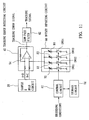
- Fig. 1 shows, in sections (Sa), (Sd) and (Se), various signal waveforms found at points (a), (d) and (e) in the circuitry of Figs. 5 and 6 , where same reference characters as those in Fig. 8 denote same signals
- the "A+D” and "B+C” light signals assume waveforms as shown in section (Sa), from which it will be seen that when influenced by residual heat from an adjoining track inward of the currently-recorded track, the "A+D” or inner reflected light reception signal (denoted in dotted line) in an ON period of the recording pulse signal becomes lower in level than the "B+C” or outer reflected light reception signal (denoted in solid line).
- the sampling pulse (Sd) rises at a given time point after the reflected light reception signal starts declining from its peak level in the ON (high-level) period of the recording pulse signal (Sa), and then falls at the same time the recording pulse signal (Sa) is next turned on and starts rising in level).
- the rising timing of the sampling pulse (Sd) varies depending on the recording conditions, while the falling timing of the sampling pulse (Sd) remains constant.
- a rear segment of the recording pulse ON period is incorporated to the sampling time as denoted by a double-headed arrow AR in section (Sd). While the sampling pulse (Sd) is ON (in the high-level state) (i.e., during the sampling time), the switches SW1 and SW2 of Fig.
- one of the "A+D” and “B+C” reflected light reception signals would become greater in level than the other reflected light reception signal due to a deviation of the laser light beam 20 off the center line of the currently-recorded track.
- the inner reflected light reception signal (“A+D") becomes greater in level than the outer reflected light reception signal (“B+C”); however, if the laser light beam 20 deviates outwardly or toward the outer circumference, then the outer reflected light reception signal (“B+C”) becomes greater in level than the inner reflected light reception signal (“A+D").
- Relation between the deviating direction of the laser light beam 20 and the corresponding level increase/decrease of the A+D" and "B+C” reflected light reception signals in the ON period of the recording pulse signal is opposite to that in the OFF period of the recording pulse signal.
- the level of the A+D" and "B+C” reflected light reception signals would normally be varied much more greatly by the residual heat from the adjoining inner track than by the tracking error itself.
- the residual heat influence can be a dominant factor of level variation of the tracking signal ("B+C"-"A+D") (i.e., the tracking error signal having been smoothed by the low-pass filter 42), corresponding to the deviation of the laser light beam 20 relative to the currently-recorded track.
- the level decrease amount of the "A+D" reflected light reception signal in the recording pulse ON period becomes greater than the level increase amount of the same signal in the recording pulse OFF period, so that the tracking signal ("B+C"-"A+D”) assumes a greater value.
- the level increase amount of the "A+D" reflected light reception signal in the recording pulse ON period becomes greater than the level increase amount of the "B+C” reflected light reception signal in the recording pulse OFF period, so that the tracking signal ("B+C"-"A+D") assumes a smaller value.
- the servo circuit 44 is controlled to find a particular point where a minimum absolute value of the tracking signal ("B+C"-"A+D") is obtained: more specifically, the servo circuit 44 constantly monitors relation between a direction of radial displacement of the laser light beam 20 relative to the optical disk surface and the increase/decrease in the absolute value of the tracking signal ("B+C"- "A+D"), so as to shift the laser light beam 20, radially of the optical disk, in such a direction where the absolute value of the tracking signal is minimized. Thus, the laser light beam 20 is shifted radially outward relative to the track center line 28, so as to minimize the level of the tracking signal ("B+C"-"A+D").
- the tracking signal (B+C"-"A+D) assumes a smaller value.
- the level of the "B+C” signal becomes gradually greater due to a tracking error while the ratio, of the level increase amount of the "A+D” signal, to the outward shift amount of the laser light beam 20 becomes gradually smaller. Accordingly, the level of the tracking signal (“B+C"-"A+D") turns, at a particular point, from a decreasing path to an increasing path.
- the servo circuit 44 causes the laser light beams 20 to be placed in such an offset position as to achieve a minimized level of the tracking signal ("B+C"-"A+D").
- the offset amount of the laser light beam 20 is varied depending on the length of the ON-period segment of the recording pulse signal that is to be incorporated into the sampling time. Accordingly, by set-ting an appropriate length of the ON-period segment of the recording pulse signal (i.e., by modifying the rising timing of the sampling pulse), a pit can be formed accurately on and along the center line of the recording track.
- Fig. 9 is a graph showing exemplary relation between tracking error balance and pit jitter when recording is performed on high-density optical disks, each having a 1.15 ⁇ m track pitch but having a different dye layer film thickness, while variously changing the tracking error balance.
- film thicknesses I to 5 decrease in the ascending order of the film thickness number: that is, film thickness 1 is the greatest of all, film thickness 2 is the second greatest, and so on. From the graph, it is seen that with greater film thicknesses, the tracking error balance value attaining minimum pit jitter would greatly deviate from 0% due to the residual heat from the adjoining inner track. Thus, according to the embodiment, with greater film thicknesses, the holding time length is made shorter (i.e., a shorter delay time is selected in the delay-time switching circuit 56 of Fig. 7 ). This approach can form pits accurately centered on the track center line, irrespective of the film thickness.
- optical disks with a cyanine-based dye layer generally have a greater film thickness than those with a phtalocyanine-based dye layer, a greater offset amount of the laser light beam 20 is set for the former-type disks than for the latter-type disks.
- the offset amount of the laser light beam 20 is varied in accordance with a selected recording speed magnification, the residual heat from the adjoining inner track would influence more greatly as the selected recording speed gets higher, so that it is arranged to increase the offset amount in accordance with an increase in the recording speed.
- the offset amount of the laser light beam 20 may be zero.
- the tracing signal is allowed to pass without being held anywhere in the sample and hold circuit 38.
- the tracking servo and focus servo gains are set to high values during reproduction, but set to lower values during recording so as to present the servo loop from being saturated white the recording is in progress.
- Offset imparting circuit 60 includes a plurality of variable resistors R1 to R4 connected in parallel and set to different resistance values. These variable resistors R1 to R4 are grounded at one end through respective analog switches SW11 to SW14, and connected at the other end to a non-inverting input of a same operational amplifier that constitutes the above-mentioned subtracter 54 of the tracking error detecting circuit 40. Turning on any one of the switches SW11 to SW14 changes the level of the outer or "B+C" reflected light reception signal to be applied to the non-inverting input of the operational amplifier, thereby resulting in a change of the offset amount.
- a control circuit 62 reads out the ON/OFF information on a selected one of the switches SW11 to SW14 so as to control the selected switch in a manner corresponding to the recording conditions.
- Such control by the control circuit 62 can form pits accurately on and along the track center line.
- the sample and hold circuit, 38 allows the tracking error signal to pass therethrough for an OFF period of the recording pulse signal or non-pit-forming period, but holds the tracking signal for an ON period of the recording pulse signal or pit-forming period.
- This control may be used in combination with the variable control of sampling and holding times based on the recording conditions as discussed earlier in relation to the first device and such combined control allows pits to be formed even more accurately on and along the track center line.
- the current tracking error signal may be set to a zero level in stead of the preceding tracking error signal being held by the sample and hold circuit.
- various digital offset values may be prestored in memory so that a suitable one of the stored values corresponding to the current recording conditions can be selectively read out and used in the tracking control.
- the devices have been described as recording information on a track formed as a groove of an optical disk ("groove recording")
- the recording track may be a land of the optical disk and recording").
- the present disclosure is also applicable to cases where tracking error detecting schemes other than the push-pull method are employed.
- the present disclosure can be applied to recording on various other optical disks than the CD-R media.
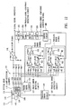
- Fig. 12 is a block diagram showing en exemplary structure of an optical disk recording drive, also capable of reproducing recorded information, in accordance with a first embodiment of the present invention.
- This optical disk drive 111 is characterized by automatized servo balance adjustment.
- In the recording surface of an optical disk 110 there are formed, as recording tracks, guide grooves (pre-grooves) that wind or wobble in predetermined cycles.
- the frequency of the wobbles is set at 22.05 kHz for the normal (one-time) speed mode.
- the optical disk 110 is driven to rotate via a spindle motor 112, and specified information is recorded and reproduced using a laser light 116 irradiated from an optical head 114.
- Reflection of the irradiated laser light beam 116 from the optical disk 110 is received by a quadruple PIN photo diode 118 within the optical head 114 which forms four light-receiving elements.
- Reflected light reception signals A, B, C and D from the light-receiving elements are passed to corresponding current/voltage converting circuit 120, 122, 124 and 126, where each of the signals is converted to a signal having a voltage value corresponding to the signal's current value.
- Summing amplifiers 128 and 130 add together the reflected light reception signals A, C and B, D, respectively.
- Subtracting amplifier 132 calculates a difference between the added results, i.e., (8+D)-(A+C), to thereby provide a focus error signal.
- Focus servo circuit 134 drives a focus actuator 136 within the optical head 114 on the basis of the focus error signal from the subtracting amplifier 132, to thereby perform focus control.
- focus servo balance adjustment is effected by adjusting a power-controllirig (e.g., voltage-controlling) variable resistor VR1 in a voltage divider circuit.
- the voltage divider circuit also including resistance R1, divides an output voltage of the summing amplifier 130 and passes the divided voltage to a non-inverting input of the subtracting amplifier 132.
- tracking servo circuit 144 drives a tracking actuator 146 within the optical head 114 on the basis of the tracking error signal from the subtracting amplifier 142, to thereby perform tracking control.
- tracking servo balance adjustment is effected by adjusting a power-controlling (e.g., voltage-controlling) variable resistor VR2 in another voltage divider circuit.
- This voltage divider circuit also including resistance R2, divides an output voltage of the summing amplifier 140 and passes the divided voltage to a non-inverting input of the subtracting amplifier 142.
- Summing amplifier 148 sums up all the reflected light reception signals (i.e., A+B+C+D) to thereby provide an HF (High Frequency) signal.
- the HF signal is delivered to a wobble-corresponding-component detecting circuit 150 as well as a signal reproduction processing system (not shown).
- the HF signal having been delivered to the wobble-corresponding-component detecting circuit 150 is first applied to a band-pass filter 1.52 whose center frequency is set to equal the fundamental frequency of the wobble that is for example, 22.05 kHz x n (n represents a recording speed magnification) for the CD-R media: the band-pass filter 152 thus extracts a wobble-corresponding component that corresponds to the frequency of the wobbles on the track.
- the extracted wobble-corresponding component is amplified by an amplifier 154, rectified by a rectifier 156, and smoothed by a low-pass filter 158, to provide a d.c. signal corresponding to the amplitude of the wobble-corresponding component (wobble-corresponding-component detection signal).
- Control circuit 160 controls the above-mentioned variable resistors VR1 and VR2 on the basis of the wobble-corresponding-component detection signal, to thereby automatically adjust the focus servo balance and tracking servo balance into optimum conditions.
- Fig. 14 there are shown jitter variations measured in reproduction of information that is recorded while changing the resistance of the focus-servo-balance adjusting variable resistor VR1.
- the point where the jitter is at its smallest level is where optimum focus servo balance appears to exist.
- Fig. 15 there are shown variations in voltage value of the wobble-corresponding-component detection signal when information is recorded while changing the resistance of the focus-servo-balance adjusting variable resistor VR1. From Figs. 14 and 15 , it is seen that the value of the variable resistor VR1 achieving the lowest jitter level is substantially equal to the value of the variable resistor VR1 achieving the lowest level of the wobble-corresponding component.
- Fig. 17 there are shown jitter variations measured in reproduction of information that is recorded while changing the resistance of the tracking-servo-balance adjusting variable resistor VR2.
- the point where the jitter is at its smallest level is where optimum tracking servo balance appears to exist.
- Fig. 18 there are shown variations in voltage value of the wobble-corresponding-component detection signal when informations is recorder while changing the resistance of the tracking-servo-balance adjusting variable resistor VR2. From Figs. 17 and 18 , it is seen that the value of the variable resistor VR2 achieving the lowest jitter level is substantially equal to the value of the variable resistor VR2 achieving the lowest level of the wobble-corresponding component.
- control circuit 160 of Fig. 12 is arranged to adjust the two variable resistors VR1 and VR2 in such a manner that the wobble-corresponding-component detection signal presents its lowest level during recording.
- the adjustment by the control circuit 160 may be realized, for example, by prestoring such values of the variable resistors VR1 and VR2 that may achieve the lowest level of the wobble-corresponding-component detection signal, through trial recording where information is recorded on a power calibration area (PCA) of the disk located inward of the disk's lead-in area while varying the values of the variable resistors VR1 and VR2, and then carrying out actual recording with the variable resistors VR1 and VR2 fixed to the prestored values.
- PCA power calibration area
- variable resistors VR1 and VR2 may be adjusted in real time by constantly changing them in such a way that the level of the wobble-corresponding-component detection signal is lowered. With this real-time adjustment, it is possible to properly address a difference in optimum servo balance conditions due to different film thicknesses of the dye layer between the inner and outer portions of the optical disk.
- variable resistor VR1 and resistance R1 may be reversed.
- positions of the other variable resistor VR2 and resistance R2 may be reversed.
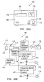
- FIG. 20A shows a front panel 166 of the optical disk drive 164, on which are provided a doorway 170 to a disk tray 168, a focus-servo-balance adjusting knob 172, a tracking-servo-balance adjusting knob 174 and a wobble-corresponding-component level meter 176.
- Fig. 20B is a block diagram showing an exemplary internal organization of the optical disk drive 164, where same elements as those of Fig. 12 are denoted by same reference characters as in the figure.
- Variable resistors VR1 in a focus error detecting circuit 127 is a manual variable resistor whose resistance value is adjustable by the user via the focus-servo-balance adjusting knob 172.
- a variable resistor VR2 in a tracking error detecting circuit 137 is a manual variable resistor whose resistance value is adjustable by the user via the tracking-servo-balance adjusting knob 174.
- the positions of the variable resistor VR1 and resistance R1 are reversed from those in Fig. 12 , and so are the positions of the variable resistor VR2 and resistance R2.
- Wobble-corresponding-component detection signal (i.e., a d.c. signal varying in level in accordance with the amplitude of a wobble-corresponding component contained in the HF signal) output from the wobble-corresponding component detecting circuit 150 is passed through a driver 177 to the level meter 176, where the signal level is visually displayed.
- the optical disk 110 is set in place, and the optical disk drive 164 is placed in a recording mode or trial recording mode.
- the user turns the focus-servo-balance adjusting knob 172 and tracking-servo-balance adjusting knob 174 while viewing, the level meter 176 and stops turning the knobs 172 and 174 at positions where the level meter 176 presents a minimum level of the wobble-corresponding-component detection signal; specifically one of the knobs 172 or 174 is first turned to find the minimum level and then the other knob 174 or 112 is turned to find the minimum level.
- Figs. 21A and 21B show a servo balance detecting device for use with an optical disk drive, which embodies a third embodiment of the present invention. More specifically.
- Fig. 21A is an external view of the servo balance detecting device while
- Fig. 21a is a block diagram showing an internal structure of the device, where same elements as those in Fig. 20 are denoted by same reference characters as in the figure.
- the servo balance detecting device 78 includes an HF signal input 180 for receiving the HF signal from the optical disk drive, and the level meter 176 as described above in relation to Fig. 20 .
- the HF signal received via the signal input 180 is first delivered to the wobble-corresponding component detecting circuit 150 for detection of a wobble-corresponding component, and a level of the detected wobble-corresponding component is visually shown on the level meter 176.
- the optical disk is set in place within the optical disk drive, and the optical disk drive is placed in a recording mode or trial recording mode. Then, the user turns the focus-servo-balance adjusting knob that is set to a half-fixed resistance value, and stops turning the knob at a particular position where the level meter 176 presents a minimum level of the wobble-corresponding-component detection signal.
Landscapes
- Optical Recording Or Reproduction (AREA)
Claims (4)
- Verfahren zur Anpassung des Servoausgleichs zur Verwendung mit einer Aufzeichnungsvorrichtung für optische Platten zum Aufzeichnen von Information durch Ausstrahlen eines Laserlichtstrahls (116) auf eine optische Platte (110), die eine Spur besitzt, die in vorbestimmten Zyklen taumelt, wobei das Verfahren zur Anpassung des Servoausgleichs die folgenden Schritte aufweist:Detektieren einer Taumelkomponente, zugehörig zu einem Wobbeln bzw. Taumeln der Spur, die in reflektierten Lichtempfangssignalen (A, B, C, D) enthalten ist, die durch Empfangen einer Reflektion des Laserlichtstrahls (116) von der optischen Platte (110) während des Aufzeichnens auf der optischen Platte (110) erzeugt wird; undAnpassen des Niveauausgleichs zwischen den reflektierten Lichtempfangssignalen (A, B, C, D) zur Verwendung bei der Berechnung eines Servofehlers in einer solchen Art und Weise, dass die Taumelkomponente, die durch den Schritt des Detektierens detektiert wird, ein im Wesentlichen minimales Niveau darstellt.
- Aufzeichnungsvorrichtung für optische Platten, die Folgendes aufweist:einen optischen Kopf (114), der einen Laserlichtstrahl (116) zur Aufzeichnung auf eine optische Platte (110) ausstrahlt um Information darauf aufzuzeichnen und eine Reflektion des Laserlichtstrahls (116) von der optischen Platte (110) empfängt, um reflektierte Lichtempfangssignale (A, B, C, D) zu liefern;einen Taumelkomponentendetektionsabschnitt (150), der eine Taumelkomponente zugehörig zu einem Taumeln einer Spur auf der optischen Platte (110) detektiert, die in den reflektierten Lichtempfangssignalen (A, B, C, D) während des Aufzeichnens auf der optischen Platte (110) enthalten ist:einen Servofehlerdetektionsabschnitt (128, 130, 132, 138, 140, 142, 148), der einen Servofehler durch Ausführen arithmetischer Betriebe zwischen den reflektierten Lichtempfangssignalen (A, B, C, D) detektiert;einen Servoabschnitt (134; 144), der den Servofehler durch Antreiben einer Servobetätigungsvorrichtung (136; 146) auf der Basis des Servofehlers korrigiert, der durch den Servofehlerdetektionsabschnitt (128, 130, 132; 138, 140, 142, 148) detektiert wird;einen Anpassungsabschnitt (VR1, VR2), der den Niveauausgleich zwischen den reflektierten Lichtempfangssignalen (A, B, C, D), die in den arithmetischen Betrieben verwendet werden sollen, die durch den Servofehlerdetektionsabschnitt (128, 130, 132, 138, 140, 142, 148) ausgeführt werden; undeinen Steuerabschnitt (160), der angepasst ist, um während des Aufzeichnens automatisch den Niveauausgleich zwischen den reflektierten Lichtempfangssignalen (A, B, C, D) anzupassen, und zwar durch Steuern des Anpassungsabschnitts (VR1, VR2) in einer solchen Art und Weise, dass die Taumelkomponente, die durch den Taumelkomponentendetektionsabschnitt (150) detektiert wird, ein im Wesentlichen minimales Niveau darstellt.
- Aufzeichnungsvorrichtung (164) für optische Platten, die Folgendes aufweist:einen optischen Kopf (114), der einen Laserlichtstrahl (116) zum Aufzeichnen auf eine optische Platte (110) ausstrahlt, um Information auf diese aufzuzeichnen und der eine Reflektion des Laserlichtstrahls (116) von der optischen Platte (110) empfängt, um Empfangssignale des reflektierten Lichts vorzusehen;einen Taumelkomponentendetektionsabschnitt (150), der eine Taumelkomponente detektiert, zugehörig zu einem Taumeln einer Spur auf der optischen Platte (110), die in den reflektierten Empfangssignalen während des Aufzeichnens auf der optischen Platte (110) enthalten ist;eine Anzeige (176), die ein Niveau der Taumelkomponente anzeigt, das durch den Taumelkomponentendetektionsabschnitt (150) detektiert wird;einen Servoabschnitt (134, 144), der den Servofehler durch Antreiben eines Servobetätigers auf der Basis des Servofehlers korrigiert, der durch den Servofehlerdetektionsabschnitt (127, 137) detektiert wird;einen Anpassungsabschnitt (VR1, VR2), der den Niveauausgleich zwischen den Empfangssignalen des reflektierten Lichts anpasst, die in den arithmetischen Vorgängen verwendet werden sollen, die durch den Servofehlerdetektionsabschnitt (127, 137) ausgeführt werden; undeine Anpassungsvorrichtung für den Niveauausgleich (172, 174), die betriebsbereit ist, um manuell den Niveauausgleich zwischen den Empfangssignalen des reflektierten Lichts durch Steuern des Anpassungsabschnitts (VR1, VR2) in einer solchen Art und Weise anzupassen, dass die Taumelkomponente, die durch den Taumelkomponentendetektionsabschnitt (150) detektiert wird, ein im Wesentlichen minimales Niveau darstellt.
- Servoausgleichsdetektionsvorrichtung (178), die Folgendes aufweist:einen Eingabeanschluss- bzw. Eingabeterminalabschnitt (180), der Empfangssignale des reflektierten Lichts zugehörig zu einer Reflektion eines Laserlichtstrahls der Aufzeichnung empfängt, der durch eine Aufzeichnungsvorrichtung für optische Platten auf eine optische Platte ausgestrahlt wird;einen Taumelkomponentendetektionsabschnitt (150), der eine Taumelkomponente zugehörig zu einem Taumeln einer Spur auf der optischen Platte detektiert, das in den Empfangssignalen des reflektierten Lichts enthalten ist, die über den Eingabeterminalabschnitt (180) empfangen werden; undeine Anzeige (176), die ein Niveau der Taumelkomponente anzeigt, das durch den Taumelkomponentendetektionsabschnitt (150) detektiert wird.
Applications Claiming Priority (3)
| Application Number | Priority Date | Filing Date | Title |
|---|---|---|---|
| JP04875698A JP3159157B2 (ja) | 1998-02-13 | 1998-02-13 | 光ディスク記録方法および光ディスク記録装置 |
| JP10199688A JP2000020968A (ja) | 1998-06-30 | 1998-06-30 | 光ディスク記録装置のサーボバランス調整方法、光ディスク記録装置およびサーボバランス検出装置 |
| EP99103017A EP0936602B1 (de) | 1998-02-13 | 1999-02-15 | Aufzeichnungstechnik für optische Platten zur Bildung von genau spurzentrierten Pits und Servoabgleicheinstellungstechnik zur Aufzeichnung auf optischen Platten |
Related Parent Applications (2)
| Application Number | Title | Priority Date | Filing Date |
|---|---|---|---|
| EP99103017.2 Division | 1999-02-15 | ||
| EP99103017A Division EP0936602B1 (de) | 1998-02-13 | 1999-02-15 | Aufzeichnungstechnik für optische Platten zur Bildung von genau spurzentrierten Pits und Servoabgleicheinstellungstechnik zur Aufzeichnung auf optischen Platten |
Publications (3)
| Publication Number | Publication Date |
|---|---|
| EP1710792A2 EP1710792A2 (de) | 2006-10-11 |
| EP1710792A3 EP1710792A3 (de) | 2009-02-18 |
| EP1710792B1 true EP1710792B1 (de) | 2013-04-10 |
Family
ID=26389068
Family Applications (2)
| Application Number | Title | Priority Date | Filing Date |
|---|---|---|---|
| EP99103017A Expired - Lifetime EP0936602B1 (de) | 1998-02-13 | 1999-02-15 | Aufzeichnungstechnik für optische Platten zur Bildung von genau spurzentrierten Pits und Servoabgleicheinstellungstechnik zur Aufzeichnung auf optischen Platten |
| EP06012735.4A Expired - Lifetime EP1710792B1 (de) | 1998-02-13 | 1999-02-15 | Verfahren zur Einstellung des Servoausgleichs zur optischen Plattenaufzeichnung |
Family Applications Before (1)
| Application Number | Title | Priority Date | Filing Date |
|---|---|---|---|
| EP99103017A Expired - Lifetime EP0936602B1 (de) | 1998-02-13 | 1999-02-15 | Aufzeichnungstechnik für optische Platten zur Bildung von genau spurzentrierten Pits und Servoabgleicheinstellungstechnik zur Aufzeichnung auf optischen Platten |
Country Status (3)
| Country | Link |
|---|---|
| US (1) | US6643239B2 (de) |
| EP (2) | EP0936602B1 (de) |
| DE (1) | DE69933251T2 (de) |
Families Citing this family (15)
| Publication number | Priority date | Publication date | Assignee | Title |
|---|---|---|---|---|
| JP3602975B2 (ja) * | 1998-11-12 | 2004-12-15 | アルプス電気株式会社 | 光ディスク装置 |
| US6912190B2 (en) * | 2000-11-15 | 2005-06-28 | Matsushita Electric Industrial Co., Ltd. | Optical disc apparatus and method for reading information from an optical disk having tracks and spaces between the tracks on which address information is recorded |
| JP3690289B2 (ja) * | 2001-02-19 | 2005-08-31 | ティアック株式会社 | 光ディスク装置 |
| JP2003059068A (ja) * | 2001-08-22 | 2003-02-28 | Funai Electric Co Ltd | ディスク装置及びサーボ機構の調整方法 |
| JP3632641B2 (ja) * | 2001-09-07 | 2005-03-23 | ティアック株式会社 | 光ディスク装置 |
| JP3914018B2 (ja) * | 2001-09-26 | 2007-05-16 | 株式会社リコー | ウォブル信号検出装置及び光学的情報記録再生装置 |
| KR20030042913A (ko) * | 2001-11-26 | 2003-06-02 | 삼성전자주식회사 | 기록/재생 장치 및 그 제어 방법 |
| JP4029976B2 (ja) * | 2002-12-26 | 2008-01-09 | 株式会社リコー | パルス形状調整方法、記録方法及び情報記録再生装置 |
| JP2004334983A (ja) * | 2003-05-08 | 2004-11-25 | Sony Corp | 記録再生装置、記録再生方法 |
| US7616536B2 (en) * | 2003-05-21 | 2009-11-10 | Koninklijke Philips Electronics N.V. | Apparatus for radial tracking in an optical disc drive using tracking an error signal derived from wobble-induced signal components and/or data-induced signal components of a detector output |
| JP2005166080A (ja) * | 2003-11-28 | 2005-06-23 | Matsushita Electric Ind Co Ltd | 光ディスク装置 |
| TWI236009B (en) * | 2004-03-25 | 2005-07-11 | Via Tech Inc | Sample-and-hold interface circuit of a pickup head |
| US7715303B2 (en) * | 2005-09-27 | 2010-05-11 | Mediatek Incorporation | Recording apparatus for optical data |
| JP2008123640A (ja) * | 2006-11-15 | 2008-05-29 | Funai Electric Co Ltd | 光ディスク装置 |
| TWI346953B (en) * | 2007-06-26 | 2011-08-11 | Quanta Storage Inc | Apparatus and method for calibrating focus balance in an optical disk drive |
Family Cites Families (26)
| Publication number | Priority date | Publication date | Assignee | Title |
|---|---|---|---|---|
| JPS5753840A (ja) | 1980-09-17 | 1982-03-31 | Mitsubishi Electric Corp | Tsuisekisochi |
| US4866688A (en) * | 1985-12-20 | 1989-09-12 | Hitachi, Ltd. | Composite tracking servo system for optical disc apparatus with track offset correction |
| JP2559372B2 (ja) * | 1986-07-09 | 1996-12-04 | 株式会社日立製作所 | 光ディスク装置及び光情報記録方法 |
| JPS63142533A (ja) * | 1986-12-03 | 1988-06-14 | Fujitsu Ltd | 光学的記録再生装置 |
| JP2911449B2 (ja) * | 1987-10-29 | 1999-06-23 | パイオニア株式会社 | 光学式情報読取装置 |
| US5126994A (en) * | 1988-11-29 | 1992-06-30 | Sony Corporation | Method and apparatus for controlling and detecting recording laser beam |
| JP2734054B2 (ja) * | 1989-02-03 | 1998-03-30 | ソニー株式会社 | 光ディスク装置のトラッキングエラー検出装置及びトラッキングエラー検出方法 |
| KR950010418B1 (ko) * | 1991-08-28 | 1995-09-16 | 미쯔비시덴끼 가부시끼가이샤 | 광기록재생장치 |
| JP3051526B2 (ja) * | 1991-11-08 | 2000-06-12 | パイオニア株式会社 | 光学式記録再生装置における光ヘッドのサーボ装置 |
| JP2850609B2 (ja) * | 1991-11-29 | 1999-01-27 | 松下電器産業株式会社 | フォーカス制御装置 |
| JP2919168B2 (ja) | 1992-04-07 | 1999-07-12 | アルパイン株式会社 | トラッキングサーボのバランス調整装置 |
| JP2605577B2 (ja) * | 1993-03-19 | 1997-04-30 | ヤマハ株式会社 | 光ディスク記録装置 |
| US5878007A (en) * | 1993-12-27 | 1999-03-02 | Matsushita Electric Industrial Co., Ltd. | Anti-wobble optical medium and tracking method and apparatus |
| JPH07201058A (ja) * | 1993-12-30 | 1995-08-04 | Victor Co Of Japan Ltd | トランスデューサ調整装置 |
| US5440534A (en) * | 1994-01-10 | 1995-08-08 | Eastman Kodak Company | Method and apparatus for maintaining a recording light beam in an on-track position on a recording medium |
| JPH08306054A (ja) * | 1995-04-28 | 1996-11-22 | Sony Corp | トラッキングサーボ回路 |
| US5646919A (en) * | 1996-01-16 | 1997-07-08 | Eastman Kodak Company | Dynamic tracking control in an optical recording system by sensing mark formation |
| JPH09237421A (ja) * | 1996-03-01 | 1997-09-09 | Sony Corp | 記録再生装置および方法 |
| US5875157A (en) * | 1996-03-18 | 1999-02-23 | Sony Corporation | Tracking error detecting circuit in disc-shaped recording medium reproducing and recording apparatus |
| US5689485A (en) * | 1996-04-01 | 1997-11-18 | Discovision Associates | Tracking control apparatus and method |
| JPH1011768A (ja) * | 1996-06-19 | 1998-01-16 | Sony Corp | 光ディスク装置とその制御方法 |
| DE19630887A1 (de) * | 1996-07-31 | 1998-02-05 | Thomson Brandt Gmbh | Gerät zum Lesen und/oder Beschreiben optischer Aufzeichnungsträger |
| JPH1091983A (ja) * | 1996-09-12 | 1998-04-10 | Sony Corp | 光学式ディスク装置およびトラッキングエラー信号算出回路 |
| JPH10105968A (ja) * | 1996-09-24 | 1998-04-24 | Sony Corp | 光記録方法 |
| KR100414792B1 (ko) * | 1996-09-30 | 2004-04-03 | 주식회사 대우일렉트로닉스 | 광 디스크 플레이어의 트래킹 밸런스 제어 방법 |
| DE19723542A1 (de) * | 1997-06-05 | 1998-12-10 | Thomson Brandt Gmbh | Gerät zum Lesen und/oder Beschreiben optischer Aufzeichnungsträger |
-
1999
- 1999-02-15 EP EP99103017A patent/EP0936602B1/de not_active Expired - Lifetime
- 1999-02-15 DE DE69933251T patent/DE69933251T2/de not_active Expired - Lifetime
- 1999-02-15 EP EP06012735.4A patent/EP1710792B1/de not_active Expired - Lifetime
-
2001
- 2001-03-22 US US09/815,415 patent/US6643239B2/en not_active Expired - Fee Related
Also Published As
| Publication number | Publication date |
|---|---|
| EP1710792A3 (de) | 2009-02-18 |
| DE69933251T2 (de) | 2007-05-16 |
| US6643239B2 (en) | 2003-11-04 |
| DE69933251D1 (de) | 2006-11-02 |
| EP0936602A2 (de) | 1999-08-18 |
| US20010010667A1 (en) | 2001-08-02 |
| EP1710792A2 (de) | 2006-10-11 |
| EP0936602A3 (de) | 2002-02-20 |
| EP0936602B1 (de) | 2006-09-20 |
Similar Documents
| Publication | Publication Date | Title |
|---|---|---|
| US7046599B2 (en) | Optical disc recording method and optical disc recording apparatus for setting optimal recording power to record data | |
| US7242653B2 (en) | Optical disc apparatus capable of detecting recording characteristics based on a predetermined signal prerecorded and reproduced | |
| EP0469727B1 (de) | Gerät zum Aufzeichnen und Wiedergeben von optischen Platten | |
| US5737289A (en) | Data recording apparatus adapted for recording data signals onto an optical recording medium | |
| US5872763A (en) | Method and device for recording on optical disc | |
| EP1710792B1 (de) | Verfahren zur Einstellung des Servoausgleichs zur optischen Plattenaufzeichnung | |
| US6480450B1 (en) | Method and apparatus for recording optical information by varying recording pulse width | |
| US6442115B1 (en) | Information recording apparatus | |
| EP0557584B1 (de) | Verfahren und Vorrichtung zur Aufzeichnung von Informationen auf einer beschreibbaren optischen Platte | |
| US6950378B1 (en) | Laser power control method and optical disk device | |
| KR100952793B1 (ko) | 트랙킹 제어 장치 및 광 디스크 장치 | |
| US7133340B2 (en) | Optical disc apparatus | |
| US20050237884A1 (en) | Information recording apparatus and method, and computer program product | |
| US6208601B1 (en) | Optical information recording method and apparatus | |
| JP3773196B2 (ja) | 記録再生装置及びcav記録時のレーザパワー制御方法 | |
| US20080069158A1 (en) | Laser power control technique and apparatus for recording and reproducing data in and from optical disk under laser power control | |
| KR20010052804A (ko) | 광정보기록재생방법 및 장치 | |
| JP3159157B2 (ja) | 光ディスク記録方法および光ディスク記録装置 | |
| US7046601B2 (en) | Method of controlling laser power of main beam by monitoring sub beam | |
| JP3865123B2 (ja) | 光ディスク装置の光強度制御装置及び光強度制御方法 | |
| KR100585106B1 (ko) | 광디스크 드라이브의 런타임 기록 파워 제어 방법 및 이에적합한 장치 | |
| JP2833308B2 (ja) | 光ディスク記録装置 | |
| US7539088B2 (en) | Optical disc recording and reproducing method adaptive to wobble pregroove | |
| KR100734316B1 (ko) | 광 정보 기록 장치, 라이트 스트래티지 설정 장치, 라이트스트래티지의 설정 방법 및 프로그램 | |
| JPH0729179A (ja) | 情報記録装置 |
Legal Events
| Date | Code | Title | Description |
|---|---|---|---|
| PUAI | Public reference made under article 153(3) epc to a published international application that has entered the european phase |
Free format text: ORIGINAL CODE: 0009012 |
|
| 17P | Request for examination filed |
Effective date: 20060621 |
|
| AC | Divisional application: reference to earlier application |
Ref document number: 0936602 Country of ref document: EP Kind code of ref document: P |
|
| AK | Designated contracting states |
Kind code of ref document: A2 Designated state(s): AT BE CH CY DE DK ES FI FR GB GR IE IT LI LU MC NL PT SE |
|
| AX | Request for extension of the european patent |
Extension state: AL LT LV MK RO SI |
|
| RAP1 | Party data changed (applicant data changed or rights of an application transferred) |
Owner name: YAMAHA CORPORATION |
|
| PUAL | Search report despatched |
Free format text: ORIGINAL CODE: 0009013 |
|
| AK | Designated contracting states |
Kind code of ref document: A3 Designated state(s): AT BE CH CY DE DK ES FI FR GB GR IE IT LI LU MC NL PT SE |
|
| AX | Request for extension of the european patent |
Extension state: AL LT LV MK RO SI |
|
| 17Q | First examination report despatched |
Effective date: 20090923 |
|
| AKX | Designation fees paid |
Designated state(s): DE GB |
|
| GRAP | Despatch of communication of intention to grant a patent |
Free format text: ORIGINAL CODE: EPIDOSNIGR1 |
|
| GRAS | Grant fee paid |
Free format text: ORIGINAL CODE: EPIDOSNIGR3 |
|
| GRAA | (expected) grant |
Free format text: ORIGINAL CODE: 0009210 |
|
| AC | Divisional application: reference to earlier application |
Ref document number: 0936602 Country of ref document: EP Kind code of ref document: P |
|
| AK | Designated contracting states |
Kind code of ref document: B1 Designated state(s): DE GB |
|
| REG | Reference to a national code |
Ref country code: GB Ref legal event code: FG4D |
|
| REG | Reference to a national code |
Ref country code: DE Ref legal event code: R096 Ref document number: 69944706 Country of ref document: DE Effective date: 20130606 |
|
| PLBE | No opposition filed within time limit |
Free format text: ORIGINAL CODE: 0009261 |
|
| STAA | Information on the status of an ep patent application or granted ep patent |
Free format text: STATUS: NO OPPOSITION FILED WITHIN TIME LIMIT |
|
| 26N | No opposition filed |
Effective date: 20140113 |
|
| REG | Reference to a national code |
Ref country code: DE Ref legal event code: R097 Ref document number: 69944706 Country of ref document: DE Effective date: 20140113 |
|
| PGFP | Annual fee paid to national office [announced via postgrant information from national office to epo] |
Ref country code: DE Payment date: 20150210 Year of fee payment: 17 |
|
| PGFP | Annual fee paid to national office [announced via postgrant information from national office to epo] |
Ref country code: GB Payment date: 20150211 Year of fee payment: 17 |
|
| REG | Reference to a national code |
Ref country code: DE Ref legal event code: R119 Ref document number: 69944706 Country of ref document: DE |
|
| GBPC | Gb: european patent ceased through non-payment of renewal fee |
Effective date: 20160215 |
|
| PG25 | Lapsed in a contracting state [announced via postgrant information from national office to epo] |
Ref country code: DE Free format text: LAPSE BECAUSE OF NON-PAYMENT OF DUE FEES Effective date: 20160901 Ref country code: GB Free format text: LAPSE BECAUSE OF NON-PAYMENT OF DUE FEES Effective date: 20160215 |