EP1710470A2 - Gear wheel stop disk and method of producing it - Google Patents
Gear wheel stop disk and method of producing it Download PDFInfo
- Publication number
- EP1710470A2 EP1710470A2 EP06110251A EP06110251A EP1710470A2 EP 1710470 A2 EP1710470 A2 EP 1710470A2 EP 06110251 A EP06110251 A EP 06110251A EP 06110251 A EP06110251 A EP 06110251A EP 1710470 A2 EP1710470 A2 EP 1710470A2
- Authority
- EP
- European Patent Office
- Prior art keywords
- gear
- thrust washer
- transmission gear
- spindle
- transmission
- Prior art date
- Legal status (The legal status is an assumption and is not a legal conclusion. Google has not performed a legal analysis and makes no representation as to the accuracy of the status listed.)
- Withdrawn
Links
Images


Classifications
-
- F—MECHANICAL ENGINEERING; LIGHTING; HEATING; WEAPONS; BLASTING
- F16—ENGINEERING ELEMENTS AND UNITS; GENERAL MEASURES FOR PRODUCING AND MAINTAINING EFFECTIVE FUNCTIONING OF MACHINES OR INSTALLATIONS; THERMAL INSULATION IN GENERAL
- F16H—GEARING
- F16H1/00—Toothed gearings for conveying rotary motion
- F16H1/02—Toothed gearings for conveying rotary motion without gears having orbital motion
-
- F—MECHANICAL ENGINEERING; LIGHTING; HEATING; WEAPONS; BLASTING
- F16—ENGINEERING ELEMENTS AND UNITS; GENERAL MEASURES FOR PRODUCING AND MAINTAINING EFFECTIVE FUNCTIONING OF MACHINES OR INSTALLATIONS; THERMAL INSULATION IN GENERAL
- F16H—GEARING
- F16H55/00—Elements with teeth or friction surfaces for conveying motion; Worms, pulleys or sheaves for gearing mechanisms
- F16H55/02—Toothed members; Worms
- F16H55/17—Toothed wheels
-
- F—MECHANICAL ENGINEERING; LIGHTING; HEATING; WEAPONS; BLASTING
- F16—ENGINEERING ELEMENTS AND UNITS; GENERAL MEASURES FOR PRODUCING AND MAINTAINING EFFECTIVE FUNCTIONING OF MACHINES OR INSTALLATIONS; THERMAL INSULATION IN GENERAL
- F16H—GEARING
- F16H1/00—Toothed gearings for conveying rotary motion
- F16H1/02—Toothed gearings for conveying rotary motion without gears having orbital motion
- F16H1/04—Toothed gearings for conveying rotary motion without gears having orbital motion involving only two intermeshing members
- F16H1/12—Toothed gearings for conveying rotary motion without gears having orbital motion involving only two intermeshing members with non-parallel axes
- F16H1/16—Toothed gearings for conveying rotary motion without gears having orbital motion involving only two intermeshing members with non-parallel axes comprising worm and worm-wheel
Definitions
- the invention relates to a transmission gear with a thrust washer, and a method for producing a transmission gear with thrust washer according to the preamble of the independent claims.
- a worm gear has become known in which a arranged on an output shaft worm wheel is driven by means of a screw having an input shaft.
- a circumferential annular groove is formed in the output shaft.
- the bearing plate surrounds the annular groove of the output shaft over the circumference, this is designed for mounting reasons in two parts.
- the production and assembly of such a two-piece thrust washer in the gear housing and in the groove of the output shaft is quite complex and has a tolerance chain result, which allows only an unsatisfactory longitudinal clearance compensation of the drive shaft.
- the device and the method according to the invention with the features of the independent claims have the advantage that a transmission gear is generated with an integrated thrust washer whose axial tolerances are reduced with respect to the engagement in the annular groove of the transmission gear to a minimum. Thereby is an axial fixation possibility of the transmission gear created in one operation, which has an optimal longitudinal backlash compensation in the installed state. Due to the one-piece design of the thrust washer eliminates a complex adjustment of a plurality of dividing discs, or tilting of the multiple parts is prevented in the annular groove of the transmission gear.
- an advantage is when the outer contour of the thrust washer, for example, has an approximately quadrangular shape. As a result, a reliable rotation with respect to the gear housing is provided, wherein the outer contour can also be varied, as long as it forms a sufficient form fit with respect to their rotation in the gear housing. As a result, co-rotation of the thrust washer with the transmission gear is prevented in a simple manner.
- the gearwheel is formed as a worm wheel with an external worm wheel toothing.
- this worm wheel can be driven by means of a worm which is arranged, for example, on an output shaft of an electric motor.
- the transmission gear is additionally formed as a ring gear
- the drive torque can be transmitted in a very small space to a spindle which is arranged in the worm gear.
- the gear ring gear meshes, for example, with a dipping spindle, longitudinal adjustment of a part to be adjusted can be realized in both directions.
- the thrust washer made of metal - preferably steel - made, and the gear wheel made of plastic - for example POM - sprayed. This results in an optimal material combination, resulting in minimal friction and minimal wear.
- the inventive transmission gear is installed in a spindle gear, in which both the drive element, and the spindle, which penetrates the transmission gear, are arranged in a compact gear housing.
- the thrust washer integrated in the transmission gear is pressed with slight pressure into a corresponding receptacle in the transmission housing, so that no axial play occurs between the thrust washer and the transmission housing. This eliminates the installation of an additional clamping element, as is necessary, for example, in the assembly of separate thrust washers to eliminate the longitudinal clearance, for example, each rest on one axial side of the transmission gear.
- the receptacle in the gear housing for example, transverse to the axial direction of the gear wheel also has an approximately quadrangular shape, whereby the positive connection for rotation of the thrust washer is created.
- a particularly favorable installation of the transmission results when the transmission gear is used transversely to the drive shaft in a main body of the transmission housing, wherein the thrust washer are inserted into the receptacles and the radial bearing surfaces of the transmission gear in corresponding radial bearings. Thereafter, the gear housing can be closed by mounting a cover radially to the transmission gear, whereby the transmission gear is fixed by means of the radial bearing surfaces and by means of the thrust washer both radially, and axially reliable.
- the inventive method can be mounted in a single operation in a simple way the thrust washer with respect to the transmission gear both radially and axially with minimal tolerances.
- the integration of the thrust washer as an insert in the injection-molded gear wheel eliminates a subsequent assembly and adjustment of the thrust washer with respect to the transmission gear, and the threaded spindle arranged therein.
- the relatively high material shrinkage of the plastic allows the shrinkage of the material after spraying and after cooling of the transmission gear no more plastic pressure is exerted on the thrust washer.
- the thrust washer is freely rotatable after cooling in the integrally formed by spraying annular groove with two axial side walls.
- the desired shrinkage of the plastic relative to the metallic thrust washer can be influenced, so that the longitudinal play occurring can be optimized with respect to the running friction.
- FIG. 1 shows a gearwheel 10 into which a thrust washer 12 is integrated in a rotatable manner.
- the transmission gear 10 is formed as a worm gear 14, which has external teeth 16 as a Schneckenradvertechnikung 18. For radial mounting of the gear wheel 10, this has a plurality of regions 20 with a smooth radial surface 20, by means of which the transmission gear 10 can be rotatably mounted in a transmission housing 22.
- the transmission gear 10 is further formed as a hollow gear 24 with an internal toothing 26, which for receiving a Spindle 28 is used.
- the transmission gear 10 has recesses 15 for ease of manufacture to accommodate the shape and dimensions of the transmission gear 10 according to its application.
- the internal thread 26 has, for example, a trapezoidal profile 30, so that the spindle 28 arranged therein is adjusted by the rotating gearwheel 10 along the longitudinal direction 32 of the spindle 28.
- FIG. 2 shows a further embodiment of a transmission gear 10 is shown in section, which in turn has the external teeth 16 and the internal thread 26.
- the outer toothing 16 is formed here as a spur toothing, which meshes with a drive wheel, not shown.
- the thrust washer 12 engages in an over the circumference 34 of the gear wheel 10 encircling annular groove 36 which has axial side walls 38 for the axial guidance of the thrust washer 12.
- the thrust washer 12 is formed as a one-piece annular disk 13 with two end faces 11, on which the axial side walls 38 of the annular groove 36 can be supported by an axial force.
- the thrust washer 12, 13 is shown schematically as a separate component before its integration into the transmission gear 10.
- the annular groove 36 with the two axial side walls 38 is also shown without the annular disc 13, wherein in the reality due to the manufacturing process of the transmission gear 10, the spout 12 can not be solved without destruction from the annular groove 36 out.
- the thrust washer 12 is inserted as an insert in an injection mold.
- the annular disc 13 is made of metal, for example made of steel with a round, central recess 40 and an approximately quadrangular outer contour 42.
- the plastic is injected into the injection mold, wherein at the edge portion 41 of the recess 40, the annular groove 36 of the gear wheel 10 is formed.
- the liquid plastic is applied directly to the thrust washer 12 axially and radially.
- the plastic material shrinks such that the thrust washer 12 can be solved within the annular groove 13, and can be rotated in this.
- the resulting from the shrinkage of the plastic spacings between the thrust washer 12 and the side walls 38 are in the range of a few hundredths of a millimeter, so that the transmission gear 10 with respect to the two axial directions 32 practically has a negligible Axiallnaturesspiel.
- the plastic of the transmission gear 10 also shrinks in the radial direction, so that the transmission gear 10 can rotate with very little friction when the thrust washer 12 is held.
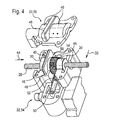
- a spindle gear 44 is shown, in which the transmission gear 10 is installed in the transmission housing 22.
- the transmission gear 10 is located with its radial bearing surfaces 20 directly into corresponding bearing mounts 46 of the gear housing 22.
- the radial bearing surfaces 20 of the transmission gear 10 are axially formed on both sides of the thrust washer 12 to prevent tilting of the transmission gear 10 under the action of axial forces.
- the thrust washer 12 is pressed into a receptacle 48 of the gear housing 22 for axial fixation of the gear wheel 10 on both sides, and thus of the spindle 28.
- first a drive shaft 50 with a worm 52 is inserted into a base body 54 of the transmission housing 22 for assembly.
- the drive shaft 50 is driven for example by an electric motor, not shown.
- the worm gear 14 is inserted with the spindle 28 disposed therein in the base body 54 that the outer teeth 16, 18 meshes with the worm 52.
- the thrust washer 12 is inserted into the pocket-like receptacle 48, wherein this forms a positive connection 58 with the thrust washer 12 with respect to the circumferential direction.
- the receptacle 48 which is formed in the base body 54 and in the cover 56, after mounting the cover 56 in the radial direction 33 also has an approximately quadrangular cross section with respect to the longitudinal direction 32. Due to the inventive method for rotatable integration of the thrust washer 12 in the transmission gear 10, the transmission 44 can be mounted very quickly and easily.
- the integrated thrust washer 12 causes both the axial bearing in both directions, as well as an optimal longitudinal clearance compensation of the spindle 28th
- the transmission gear 10 may have different external gears 16, 18 or internal gears 26.
- the invention is not limited to a hollow worm gear 14, 24 or to a spindle gear 44.
- the materials and the concrete shape of the annular disc 13 and the annular groove 36 can be varied in such a way so that after the injection molding and the cooling of the transmission gear 10, the desired game between the thrust washer 12 and the annular groove 36 sets.
- the transmission gear 10 according to the invention is used with integrated thrust washer 12 in a spindle drive 44 for a seat adjustment in the motor vehicle. The occurring during a crash high axial forces in the longitudinal direction 32 are reliably received on the transmission gear 10 and the thrust washer 12 from the gear housing 22, so that the vehicle seat remains approximately in its original position.
Abstract
Description
Die Erfindung betrifft ein Getriebezahnrad mit einer Anlaufscheibe, sowie ein Verfahren zum Herstellen eines Getriebezahnrads mit Anlaufscheibe nach der Gattung der unabhängigen Ansprüche.The invention relates to a transmission gear with a thrust washer, and a method for producing a transmission gear with thrust washer according to the preamble of the independent claims.
Mit der
Die erfindungsgemäße Vorrichtung und das erfindungsgemäße Verfahren mit den Merkmalen der unabhängigen Ansprüche haben den Vorteil, dass ein Getriebezahnrad mit einer integrierten Anlaufscheibe erzeugt wird, deren axiale Toleranzen bezüglich des Eingriffs in die Ringnut des Getriebezahnrads auf ein Minimum reduziert sind. Dadurch ist in einem Arbeitsgang eine axiale Fixierungsmöglichkeit des Getriebezahnrads geschaffen, die in eingebautem Zustand einen optimalen Längsspielausgleich aufweist. Aufgrund der einteiligen Ausführung der Anlaufscheibe entfällt eine aufwändige Justierung mehrerer Teilscheiben, bzw. wird ein Verkanten der mehreren Teile in der Ringnut des Getriebezahnrads verhindert.The device and the method according to the invention with the features of the independent claims have the advantage that a transmission gear is generated with an integrated thrust washer whose axial tolerances are reduced with respect to the engagement in the annular groove of the transmission gear to a minimum. Thereby is an axial fixation possibility of the transmission gear created in one operation, which has an optimal longitudinal backlash compensation in the installed state. Due to the one-piece design of the thrust washer eliminates a complex adjustment of a plurality of dividing discs, or tilting of the multiple parts is prevented in the annular groove of the transmission gear.
Durch die in den Unteransprüchen ausgeführten Merkmale sind vorteilhafte Weiterbildungen der Vorrichtung nach den unabhängigen Ansprüchen möglich. Durch die unlösbare Anordnung der Anlaufscheibe in der Ringnut des Getriebezahnrads entfällt ein zusätzlicher Montageschritt. Durch den Herstellungsprozess wird dabei ein optimales radiales und axiales Spiel zwischen der Anlaufscheibe und der Ringnut erzielt. Dadurch wird einerseits die Reibung zwischen dem Getriebezahnrad und der Anlaufscheibe im Betriebszustand reduziert, und andererseits steht eine zuverlässige axiale Abstützung des Getriebezahnrads, sowie der darin angeordneten Gewindespindel zur Verfügung, die auch hohe Crashkräfte aufnehmen kann.The features set out in the subclaims advantageous developments of the device according to the independent claims are possible. Due to the non-detachable arrangement of the thrust washer in the annular groove of the transmission gear eliminates an additional assembly step. Through the manufacturing process an optimal radial and axial clearance between the thrust washer and the annular groove is achieved. As a result, on the one hand the friction between the transmission gear and the thrust washer is reduced in the operating state, and on the other hand is a reliable axial support of the transmission gear, as well as the threaded spindle disposed therein, which can also absorb high crash forces.
Ein Vorteil ist es, wenn die Außenkontur der Anlaufscheibe beispielsweise eine etwa viereckige Form aufweist. Dadurch wird eine zuverlässige Verdrehsicherung bezüglich des Getriebegehäuses geschaffen, wobei die Außenkontur auch variiert werden kann, solange diese einen ausreichenden Formschluss bezüglich deren Drehung in dem Getriebegehäuse bildet. Dadurch wird auf einfache Weise ein Mitdrehen der Anlaufscheibe mit dem Getriebezahnrad unterbunden.An advantage is when the outer contour of the thrust washer, for example, has an approximately quadrangular shape. As a result, a reliable rotation with respect to the gear housing is provided, wherein the outer contour can also be varied, as long as it forms a sufficient form fit with respect to their rotation in the gear housing. As a result, co-rotation of the thrust washer with the transmission gear is prevented in a simple manner.
Besonders günstig ist es, wenn das Getriebezahnrad als Schneckenrad mit einer äußeren Schneckenradverzahnung ausgeformt ist. Dadurch kann dieses Schneckenrad mittels einer Schnecke angetrieben werden, die beispielsweise auf einer Abtriebswelle eines Elektromotors angeordnet ist.It is particularly favorable if the gearwheel is formed as a worm wheel with an external worm wheel toothing. As a result, this worm wheel can be driven by means of a worm which is arranged, for example, on an output shaft of an electric motor.
Ist das Getriebezahnrad zusätzlich als Hohlrad ausgeformt, kann das Antriebsmoment auf sehr kleinem Bauraum auf eine Spindel übertragen werden, die in dem Schneckenhohlrad angeordnet ist. Kämmt das Getriebehohlrad beispielsweise mit einer durchtauchenden Spindel, kann eine Längsverstellung eines zu verstellenden Teils in beide Richtungen realisiert werden.If the transmission gear is additionally formed as a ring gear, the drive torque can be transmitted in a very small space to a spindle which is arranged in the worm gear. If the gear ring gear meshes, for example, with a dipping spindle, longitudinal adjustment of a part to be adjusted can be realized in both directions.
In einer bevorzugten Ausgestaltung ist die Anlaufscheibe aus Metall - vorzugsweise Stahl - gefertigt, und das Getriebezahnrad aus Kunststoff - beispielsweise POM - gespritzt. Dadurch ergibt sich eine optimale Materialkombination, woraus eine minimale Reibung und ein minimaler Verschleiß resultiert.In a preferred embodiment, the thrust washer made of metal - preferably steel - made, and the gear wheel made of plastic - for example POM - sprayed. This results in an optimal material combination, resulting in minimal friction and minimal wear.
Bevorzugt wird das erfmdungsgemäße Getriebezahnrad in einem Spindelgetriebe verbaut, bei dem sowohl die Antriebselement, als auch die Spindel, die das Getriebezahnrad durchdringt, in einem kompakten Getriebegehäuse angeordnet sind.Preferably, the inventive transmission gear is installed in a spindle gear, in which both the drive element, and the spindle, which penetrates the transmission gear, are arranged in a compact gear housing.
Bei der Montage des Getriebes wird die in das Getriebezahnrad integrierte Anlaufscheibe mit leichtem Druck in eine entsprechende Aufnahme im Getriebegehäuse eingedrückt, so dass zwischen der Anlaufscheibe und dem Getriebegehäuse kein Axialspiel auftritt. Dabei entfällt die Montage eines zusätzlichen Spannelements, wie dies beispielsweise bei der Montage von separaten Anlaufscheiben zur Eliminierung des Längsspiels notwendig ist, die beispielsweise jeweils an einer axialen Seite des Getriebezahnrads anliegen.During assembly of the transmission, the thrust washer integrated in the transmission gear is pressed with slight pressure into a corresponding receptacle in the transmission housing, so that no axial play occurs between the thrust washer and the transmission housing. This eliminates the installation of an additional clamping element, as is necessary, for example, in the assembly of separate thrust washers to eliminate the longitudinal clearance, for example, each rest on one axial side of the transmission gear.
Die Aufnahme im Getriebegehäuse weist beispielsweise quer zur Axialrichtung des Getriebezahnrads ebenfalls eine annäherungsweise viereckigen Form auf, wodurch der Formschluss zur Drehsicherung der Anlaufscheibe geschaffen wird.The receptacle in the gear housing, for example, transverse to the axial direction of the gear wheel also has an approximately quadrangular shape, whereby the positive connection for rotation of the thrust washer is created.
Aufgrund der Ausbildung von glatten, radialen Lageroberflächen am Getriebezahnrad kann dieses direkt ohne zusätzliche Lagerelemente im Getriebegehäuse gelagert werden. Zur sicheren Führung des Getriebezahnrads im Getriebegehäuse ist es dabei günstig, wenn die radialen Lageroberflächen axial zu beiden Seiten der Anlaufscheibe angeordnet sind.Due to the formation of smooth, radial bearing surfaces on the gear wheel this can be stored directly without additional bearing elements in the gear housing. For safe guidance of the gear wheel in the gear housing, it is advantageous if the radial bearing surfaces are arranged axially on both sides of the thrust washer.
Eine besonders günstige Montage des Getriebes ergibt sich, wenn das Getriebezahnrad quer zur Antriebswelle in einen Grundkörper des Getriebegehäuses eingesetzt wird, wobei die Anlaufscheibe in die Aufnahmen und die radialen Lageroberflächen des Getriebezahnrads in entsprechende Radiallager eingefügt werden. Danach kann das Getriebegehäuse durch die Montage eines Deckels radial zum Getriebezahnrad verschlossen werden, wodurch das Getriebezahnrad mittels der radialen Lageroberflächen und mittels der Anlaufscheibe sowohl radial, als auch axial zuverlässig fixiert ist.A particularly favorable installation of the transmission results when the transmission gear is used transversely to the drive shaft in a main body of the transmission housing, wherein the thrust washer are inserted into the receptacles and the radial bearing surfaces of the transmission gear in corresponding radial bearings. Thereafter, the gear housing can be closed by mounting a cover radially to the transmission gear, whereby the transmission gear is fixed by means of the radial bearing surfaces and by means of the thrust washer both radially, and axially reliable.
Durch das erfindungsgemäße Verfahren kann auf einfache Weise in einem Arbeitsgang die Anlaufscheibe bezüglich dem Getriebezahnrad sowohl radial als auch axial mit minimalen Toleranzen montiert werden. Durch die Integration der Anlaufscheibe als Einlegeteil in das Spritzguss-Getriebezahnrad entfällt eine spätere Montage und Justage der Anlaufscheibe bezüglich des Getriebezahnrads, bzw. der darin angeordneten Gewindespindel. Die relativ hohe Werkstoffschwindung des Kunststoffs ermöglicht, dass beim Schwinden des Materials nach dem Spritzen und nach dem Abkühlen des Getriebezahnrads keine Kunststoffpressung mehr auf die Anlaufscheibe ausgeübt wird. Dadurch ist die Anlaufscheibe nach dem Abkühlen in der mittels Spritzen angeformten Ringnut mit zwei axialen Seitenwänden frei drehbar.The inventive method can be mounted in a single operation in a simple way the thrust washer with respect to the transmission gear both radially and axially with minimal tolerances. The integration of the thrust washer as an insert in the injection-molded gear wheel eliminates a subsequent assembly and adjustment of the thrust washer with respect to the transmission gear, and the threaded spindle arranged therein. The relatively high material shrinkage of the plastic allows the shrinkage of the material after spraying and after cooling of the transmission gear no more plastic pressure is exerted on the thrust washer. As a result, the thrust washer is freely rotatable after cooling in the integrally formed by spraying annular groove with two axial side walls.
Durch die Auswahl der Material- und Prozessparameter beim Spritzgießen- insbesondere der Wärmeausdehnungskoeffizienten-, kann die gewünschte Schrumpfung des Kunststoffes gegenüber der metallischen Anlaufscheibe beeinflusst werden, so dass das auftretende Längsspiel gegenüber der Laufreibung optimiert werden kann.By selecting the material and process parameters during injection molding - in particular the thermal expansion coefficients, the desired shrinkage of the plastic relative to the metallic thrust washer can be influenced, so that the longitudinal play occurring can be optimized with respect to the running friction.
In den Zeichnungen sind Ausführungsbeispiele einer erfmdungsgemäßen Vorrichtung dargestellt und in der nachfolgenden Beschreibung näher erläutert. Es zeigen
- Figur 1
- ein erFmdungsgemäßes Getriebezahnrad mit integrierter Anlaufscheibe,
- Figur 2
- einen Längsschnitt durch ein weiteres Ausführungsbeispiel,
- Figur 3
- zur Anschauung eine getrennt vom Getriebezahnrad dargestellte Anlaufscheibe und
- Figur 4
- einen erfmdungsgemäßen Spindelantrieb mit offenem Getriebegehäuse.
- FIG. 1
- a gearset according to the invention with integrated thrust washer,
- FIG. 2
- a longitudinal section through a further embodiment,
- FIG. 3
- for viewing a thrust washer and separately shown from the gear wheel
- FIG. 4
- a erfmdungsgemäßen spindle drive with an open gearbox.
In Figur 1 ist ein Getriebezahnrad 10 dargestellt, in das drehbar zu diesem eine Anlaufscheibe 12 integriert ist. Das Getriebezahnrad 10 ist als Schneckenzahnrad 14 ausgebildet, das als Außenverzahnung 16 eine Schneckenradverzahnung 18 aufweist. Zur radialen Lagerung des Getriebezahnrads 10 weist dieses mehrere Bereiche 20 mit einer glatten radialen Oberfläche 20 auf, mittels derer das Getriebezahnrad 10 drehbar in einem Getriebegehäuse 22 gelagert werden kann. Das Getriebezahnrad 10 ist des Weiteren als Hohlzahnrad 24 mit einer Innenverzahnung 26 ausgebildet, die zur Aufnahme einer Spindel 28 dient. Das Getriebezahnrad 10 weist aus Gründen der einfacheren Herstellung Ausnehmungen 15 auf, um die Form und die Abmessungen des Getriebezahnrads 10 entsprechend dessen Anwendung anzupassen. Das Innengewinde 26 weist beispielsweise ein Trapez-Profil 30 auf, so dass die darin angeordnete Spindel 28 durch das drehende Getriebezahnrad 10 entlang der Längsrichtung 32 der Spindel 28 verstellt wird.FIG. 1 shows a gearwheel 10 into which a thrust washer 12 is integrated in a rotatable manner. The transmission gear 10 is formed as a
In Figur 2 ist ein weiteres Ausführungsbeispiel eines Getriebezahnrads 10 im Schnitt dargestellt, das wiederum die Außenverzahnung 16 und das Innengewinde 26 aufweist. Die Außenverzahnung 16 ist hier als Stirnverzahnung ausgebildet, die mit einem nicht näher dargestellten Antriebsrad kämmt. Die Anlaufscheibe 12 greift in eine über den Umfang 34 des Getriebezahnrads 10 umlaufende Ringnut 36 ein, die axiale Seitenwände 38 zur axialen Führung der Anlaufscheibe 12 aufweist. Die Anlaufscheibe 12 ist als einteilige Ringscheibe 13 mit zwei Stirnseiten 11 ausgebildet, an denen sich die axialen Seitenwände 38 der Ringnut 36 bei axialer Krafteinwirkung abstützen kann.2 shows a further embodiment of a transmission gear 10 is shown in section, which in turn has the
In Figur 3 ist die Anlaufscheibe 12, 13 schematisch als separates Bauteil vor dessen Integration in das Getriebezahnrad 10 dargestellt ist. Die Ringnut 36 mit den beiden axialen Seitenwänden 38 ist ebenfalls ohne die Ringscheibe 13 dargestellt, wobei in der Realität aufgrund des Herstellungsprozesses des Getriebezahnrads 10 die Auslaufscheibe 12 nicht mehr aus der Ringnut 36 zerstörungsfrei heraus gelöst werden kann.In Figure 3, the thrust washer 12, 13 is shown schematically as a separate component before its integration into the transmission gear 10. The
Zur Herstellung des Getriebezahnrads 10 mit integrierter Anlaufscheibe 12 wird die Anlaufscheibe 12 als Einlegeteil in einen Spritzgussform eingelegt. Die Ringscheibe 13 ist aus Metall, beispielsweise aus Stahl mit einer runden, zentralen Aussparung 40 und einer näherungsweise viereckigen Außenkontur 42 ausgebildet. Danach wird der Kunststoff in die Spritzgussform eingespritzt, wobei am Randbereich 41 der Aussparung 40 die Ringnut 36 des Getriebezahnrads 10 angeformt wird. Zum Zeitpunkt des Einspritzens liegt der flüssige Kunststoff direkt axial und radial an der Anlaufscheibe 12 an. Nachdem das Getriebezahnrad 10 aus der Spritzgussform entfernt und abgekühlt ist, schwindet das Kunststoffmaterial derart, dass die Anlaufscheibe 12 sich innerhalb der Ringnut 13 lösen lässt, und in dieser gedreht werden kann. Die durch das Schrumpfen des Kunststoffs entstehenden Abstände zwischen der Anlaufscheibe 12 und den Seitenwänden 38 liegen im Bereich von wenigen hundertstel Millimeter, so dass das Getriebezahnrad 10 bezüglich der beiden Axialrichtungen 32 praktisch ein vernachlässigbares Axiallängsspiel aufweist. Der Kunststoff des Getriebezahnrads 10 schrumpft ebenfalls in radialer Richtung, so dass sich das Getriebezahnrad 10 bei festgehaltener Anlaufscheibe 12 unter sehr geringer Reibung drehen lässt.To produce the transmission gear 10 with integrated thrust washer 12, the thrust washer 12 is inserted as an insert in an injection mold. The annular disc 13 is made of metal, for example made of steel with a round,
In Figur 4 ist ein Spindelgetriebe 44 dargestellt, bei dem das Getriebezahnrad 10 in das Getriebegehäuse 22 eingebaut ist. Dabei liegt das Getriebezahnrad 10 mit seinen radialen Lageroberflächen 20 direkt in entsprechende Lageraufnahmen 46 des Getriebegehäuses 22 an. Die radialen Lageroberflächen 20 des Getriebezahnrads 10 sind axial auf beiden Seiten der Anlaufscheibe 12 ausgebildet, um ein Verkippen des Getriebezahnrads 10 beim Einwirken axialer Kräfte zu verhindern. Die Anlaufscheibe 12 ist zur beidseitigen axialen Fixierung des Getriebezahnrads 10 - und damit der Spindel 28 - in eine Aufnahme 48 des Getriebegehäuses 22 eingepresst. In Figur 4 wird zur Montage zuerst eine Antriebswelle 50 mit einer Schnecke 52 in einen Grundkörper 54 des Getriebegehäuses 22 eingelegt. Die Antriebswelle 50 wird beispielsweise durch einen nicht näher dargestellten Elektromotor angetrieben. Danach wird das Schneckenzahnrad 14 mit der darin angeordneten Spindel 28 derart in den Grundkörper 54 eingelegt, dass die Außenverzahnung 16, 18 mit der Schnecke 52 kämmt. Dabei wird die Anlaufscheibe 12 in die taschenartige Aufnahme 48 eingeschoben, wobei diese bezüglich der Umfangsrichtung einen Formschluss 58 mit der Anlaufscheibe 12 bildet. Bei der näherungsweise viereckigen Außenkontur 42 der Anlaufscheibe 12 weist daher die Aufnahme 48, die im Grundkörper 54 und im Deckel 56 ausgebildet ist, nach der Montage des Deckels 56 in radialer Richtung 33 ebenfalls einen näherungsweise viereckigen Querschnitt bezüglich der Längsrichtung 32 auf. Aufgrund des erfindungsgemäßen Verfahren zur drehbaren Integration der Anlaufscheibe 12 in das Getriebezahnrad 10, kann das Getriebe 44 sehr schnell und einfach montiert werden. Die integrierte Anlaufscheibe 12 bewirkt dabei sowohl die axiale Lagerung in beiden Richtungen, als auch einen optimalen Längsspielausgleich der Spindel 28.4, a
Es sei angemerkt, dass hinsichtlich der in den Figuren und der Beschreibung dargestellten Ausführungsbeispiele vielfältige Kombinationsmöglichkeiten der einzelnen Merkmale untereinander möglich sind. So kann das Getriebezahnrad 10 beispielsweise unterschiedliche Außenverzahnungen 16, 18 oder Innenverzahnungen 26 aufweisen. Die Erfindung ist dabei nicht auf ein Hohl- Schneckenzahnrad 14, 24 bzw. auf ein Spindelgetriebe 44 beschränkt. Die Werkstoffe und die konkrete Ausformung der Ringscheibe 13 und der Ringnut 36 können dabei derart variiert werden, so dass sich nach dem Spritzgießen und dem Abkühlen des Getriebezahnrads 10 das gewünschte Spiel zwischen der Anlaufscheibe 12 und der Ringnut 36 einstellt. Bevorzugt wird das erfindungsgemäße Getriebezahnrad 10 mit integrierter Anlaufscheibe 12 in einem Spindelantrieb 44 für eine Sitzverstellung im Kraftfahrzeug angewendet. Dabei werden die bei einem Crash auftretenden hohen axialen Kräfte in Längsrichtung 32 zuverlässig über das Getriebezahnrad 10 und die Anlaufscheibe 12 vom Getriebegehäuse 22 aufgenommen, so dass der Fahrzeugsitz näherungsweise in seiner ursprünglichen Position verharrt.It should be noted that, with regard to the exemplary embodiments illustrated in the figures and the description, a variety of possible combinations of the individual features are possible with one another. For example, the transmission gear 10 may have different
Claims (12)
dadurch gekennzeichnet, dass an dem Getriebezahnrad (10) über dessen Umfang (32) eine Ringnut (36) angeformt ist, in die die Anlaufscheibe (12, 13) drehbar eingreift, wobei die Anlaufscheibe (12, 13) als eine über den Umfang (32) geschlossene, einteilige Ringscheibe (13) ausgebildet ist, die unlösbar in das Getriebezahnrad (10) integriert ist.Transmission gear (10), in particular for a spindle drive (44), with external teeth (16, 18) for introducing a drive torque, and with a stop disk (12, 13) for axially fixing the transmission gear (10) in a transmission housing (22),
characterized in that on the transmission gear (10) over its circumference (32) an annular groove (36) is integrally formed, in which the thrust washer (12, 13) rotatably engages, wherein the thrust washer (12, 13) as a over the circumference ( 32) closed, one-piece annular disc (13) is formed, which is inextricably integrated in the transmission gear (10).
Applications Claiming Priority (1)
| Application Number | Priority Date | Filing Date | Title |
|---|---|---|---|
| DE102005016183A DE102005016183A1 (en) | 2005-04-08 | 2005-04-08 | Transmission gear with a thrust washer, and method for producing such |
Publications (1)
| Publication Number | Publication Date |
|---|---|
| EP1710470A2 true EP1710470A2 (en) | 2006-10-11 |
Family
ID=36676018
Family Applications (1)
| Application Number | Title | Priority Date | Filing Date |
|---|---|---|---|
| EP06110251A Withdrawn EP1710470A2 (en) | 2005-04-08 | 2006-02-22 | Gear wheel stop disk and method of producing it |
Country Status (3)
| Country | Link |
|---|---|
| EP (1) | EP1710470A2 (en) |
| KR (1) | KR20060107408A (en) |
| DE (1) | DE102005016183A1 (en) |
Cited By (2)
| Publication number | Priority date | Publication date | Assignee | Title |
|---|---|---|---|---|
| EP2952780A3 (en) * | 2014-05-28 | 2016-07-27 | Aktiebolaget SKF | Transmission |
| US11407437B2 (en) * | 2018-07-23 | 2022-08-09 | Thyssenkrupp Presta Ag | Gear wheel of an adjustment drive mechanism for a steering column and steering column for a motor vehicle |
Citations (1)
| Publication number | Priority date | Publication date | Assignee | Title |
|---|---|---|---|---|
| DE3726801C2 (en) | 1987-08-12 | 1998-04-09 | Teves Gmbh Co Ohg Alfred | Worm gear |
-
2005
- 2005-04-08 DE DE102005016183A patent/DE102005016183A1/en not_active Withdrawn
-
2006
- 2006-02-22 EP EP06110251A patent/EP1710470A2/en not_active Withdrawn
- 2006-04-07 KR KR1020060031970A patent/KR20060107408A/en not_active Application Discontinuation
Patent Citations (1)
| Publication number | Priority date | Publication date | Assignee | Title |
|---|---|---|---|---|
| DE3726801C2 (en) | 1987-08-12 | 1998-04-09 | Teves Gmbh Co Ohg Alfred | Worm gear |
Cited By (3)
| Publication number | Priority date | Publication date | Assignee | Title |
|---|---|---|---|---|
| EP2952780A3 (en) * | 2014-05-28 | 2016-07-27 | Aktiebolaget SKF | Transmission |
| US10406051B2 (en) | 2014-05-28 | 2019-09-10 | Aktiebolaget Skf | Transmission for an adjustable-height platform and method for changing a height of a platform |
| US11407437B2 (en) * | 2018-07-23 | 2022-08-09 | Thyssenkrupp Presta Ag | Gear wheel of an adjustment drive mechanism for a steering column and steering column for a motor vehicle |
Also Published As
| Publication number | Publication date |
|---|---|
| KR20060107408A (en) | 2006-10-13 |
| DE102005016183A1 (en) | 2006-10-12 |
Similar Documents
| Publication | Publication Date | Title |
|---|---|---|
| EP1797353B1 (en) | Method for producing a gearbox, and corresponding gearbox | |
| EP1658451B1 (en) | Adjustable mechanism for a motor vehicle articles and method of making such | |
| EP2710282A1 (en) | Planetary gear system | |
| DE102004013009A1 (en) | Drive for an adjusting device with a worm wheel, which has a Globoidverzahnung with cylindrical portion | |
| EP2012036A2 (en) | Catch | |
| EP0918671A1 (en) | Electric drive unit | |
| DE102006059946A1 (en) | Toothed belt wheel for motor vehicle, has hub base body with drum-shaped section and toothing made up of thermosetting plastic which lies at outer circumference of drum-shaped section | |
| DE10362326B4 (en) | Adjustment mechanism, for a vehicle seat, has a spindle nut with structured external teeth to work with a worm screw in a stable and compact structure using lightweight materials | |
| DE102010034698A1 (en) | Electromechanical steering gear for motor vehicle, has toothed belt wheels mounted at transmission component such that belt wheels are moved from displaced position into changed position in which toothed belt is stressed | |
| DE102012215247B4 (en) | Wheel bearing assembly comprising a brake disc with Radzentrierung | |
| EP2222498B1 (en) | Threaded spindle adjustment drive | |
| EP1710470A2 (en) | Gear wheel stop disk and method of producing it | |
| EP1576714B1 (en) | Drive unit for actuators in a motor vehicle | |
| EP1579125B1 (en) | Gear transmission unit | |
| EP2423036A1 (en) | Wobble drive | |
| EP1847728B1 (en) | Transmission-drive unit with a bolt and method for its manufacture | |
| WO2019166191A1 (en) | Steering system shaft bearing assembly, steering system and method for producing a steering system | |
| DE102006056938A1 (en) | Shaft arrangement of an electric motor auxiliary drive, method for securing a functional element on a shaft and spreader | |
| DE102004058177B4 (en) | gear | |
| EP3765759A1 (en) | Helical gear transmission for an electromechanical servo steering with an asymmetrically pretensioned fixed bearing | |
| WO2019192642A1 (en) | Gearing arrangement for a device for level adjustment of a vehicle structure | |
| EP2102041A1 (en) | Bearing seat arrangement for axial and radial fixation | |
| WO2005092600A1 (en) | Metal-plastic composite part having compensation for shrinkage | |
| WO2023227767A1 (en) | Planetary gear with improved bearing flange | |
| WO2003069189A1 (en) | Spindle drive and method for the production thereof |
Legal Events
| Date | Code | Title | Description |
|---|---|---|---|
| PUAI | Public reference made under article 153(3) epc to a published international application that has entered the european phase |
Free format text: ORIGINAL CODE: 0009012 |
|
| AK | Designated contracting states |
Kind code of ref document: A2 Designated state(s): AT BE BG CH CY CZ DE DK EE ES FI FR GB GR HU IE IS IT LI LT LU LV MC NL PL PT RO SE SI SK TR |
|
| AX | Request for extension of the european patent |
Extension state: AL BA HR MK YU |
|
| STAA | Information on the status of an ep patent application or granted ep patent |
Free format text: STATUS: THE APPLICATION IS DEEMED TO BE WITHDRAWN |
|
| 18D | Application deemed to be withdrawn |
Effective date: 20100901 |