EP1709366B1 - Brennkammervorrichtung für eine gasturbine mit einem system zum dämpfen von thermo-akustischer instabilität - Google Patents
Brennkammervorrichtung für eine gasturbine mit einem system zum dämpfen von thermo-akustischer instabilität Download PDFInfo
- Publication number
- EP1709366B1 EP1709366B1 EP04804871.4A EP04804871A EP1709366B1 EP 1709366 B1 EP1709366 B1 EP 1709366B1 EP 04804871 A EP04804871 A EP 04804871A EP 1709366 B1 EP1709366 B1 EP 1709366B1
- Authority
- EP
- European Patent Office
- Prior art keywords
- combustion chamber
- resonator
- casing
- combustor device
- neck
- Prior art date
- Legal status (The legal status is an assumption and is not a legal conclusion. Google has not performed a legal analysis and makes no representation as to the accuracy of the status listed.)
- Expired - Lifetime
Links
- 238000013016 damping Methods 0.000 title claims 4
- 238000002485 combustion reaction Methods 0.000 claims 17
- 210000003739 neck Anatomy 0.000 claims 6
- 239000012809 cooling fluid Substances 0.000 claims 2
- 239000007789 gas Substances 0.000 claims 2
- 238000011144 upstream manufacturing Methods 0.000 claims 2
- 230000008878 coupling Effects 0.000 claims 1
- 238000010168 coupling process Methods 0.000 claims 1
- 238000005859 coupling reaction Methods 0.000 claims 1
Images

Classifications
-
- F—MECHANICAL ENGINEERING; LIGHTING; HEATING; WEAPONS; BLASTING
- F23—COMBUSTION APPARATUS; COMBUSTION PROCESSES
- F23R—GENERATING COMBUSTION PRODUCTS OF HIGH PRESSURE OR HIGH VELOCITY, e.g. GAS-TURBINE COMBUSTION CHAMBERS
- F23R3/00—Continuous combustion chambers using liquid or gaseous fuel
- F23R3/42—Continuous combustion chambers using liquid or gaseous fuel characterised by the arrangement or form of the flame tubes or combustion chambers
- F23R3/50—Combustion chambers comprising an annular flame tube within an annular casing
-
- F—MECHANICAL ENGINEERING; LIGHTING; HEATING; WEAPONS; BLASTING
- F23—COMBUSTION APPARATUS; COMBUSTION PROCESSES
- F23M—CASINGS, LININGS, WALLS OR DOORS SPECIALLY ADAPTED FOR COMBUSTION CHAMBERS, e.g. FIREBRIDGES; DEVICES FOR DEFLECTING AIR, FLAMES OR COMBUSTION PRODUCTS IN COMBUSTION CHAMBERS; SAFETY ARRANGEMENTS SPECIALLY ADAPTED FOR COMBUSTION APPARATUS; DETAILS OF COMBUSTION CHAMBERS, NOT OTHERWISE PROVIDED FOR
- F23M20/00—Details of combustion chambers, not otherwise provided for, e.g. means for storing heat from flames
- F23M20/005—Noise absorbing means
-
- F—MECHANICAL ENGINEERING; LIGHTING; HEATING; WEAPONS; BLASTING
- F23—COMBUSTION APPARATUS; COMBUSTION PROCESSES
- F23R—GENERATING COMBUSTION PRODUCTS OF HIGH PRESSURE OR HIGH VELOCITY, e.g. GAS-TURBINE COMBUSTION CHAMBERS
- F23R2900/00—Special features of, or arrangements for continuous combustion chambers; Combustion processes therefor
- F23R2900/00014—Reducing thermo-acoustic vibrations by passive means, e.g. by Helmholtz resonators
Definitions
- the present invention relates to a combustor device comprising a system for damping thermo-acoustic instability, at least one combustion chamber and at least one burner associated to said combustion chamber and designed to serve a gas turbine, which uses passive damping means, in particular Helmholtz resonators.
- the aforementioned combustion chambers enable excellent performance both as regards efficiency of combustion and as regards the limitation of pollutant emissions and the high density of thermal yield (MWth/m 3 ).
- MWth/m 3 the high density of thermal yield
- the annular geometry associated to high densities of thermal yield can favour onset of phenomena of thermo-acoustic instability. The latter occur with marked oscillations of pressure within the combustion chamber, at well-defined frequencies that are characteristic of the geometry of the combustor and of the running conditions. Said oscillations can bring about undesirable vibrations in the turbine and damage its components.
- Some techniques are based upon decoupling of the forcing frequencies, generated by the peculiarities of the burner, from the natural frequencies of the mechanical system that enters into vibration.
- Other techniques are based upon control of the fuel in phase opposition with the onset of the pressure oscillations (active control).
- active control active control
- passive-damping systems based upon the use of dissipater devices, in particular Helmholtz resonators, which capture the acoustic waves and dampen their amplitude, dissipating the energy thereof.
- the U.S. patent No. 6,530,221 relates to a system in which the dissipaters used are not Helmholtz resonators, but perforated box-section elements.
- a dissipater element of this type can give rise to the following problems:
- the British patent application GB 2 288 660 A describes a system in which the resonators used are classic Helmholtz resonators, sized according to relations available in the literature.
- the position in which the resonators should be mounted on the combustion chamber to be effective is not clarified.
- the volume of the resonator is not adjustable, so that the operating frequency is fixed.
- the resonators are provided with a complicated system for regulation of the internal temperature so as to be able to regulate the frequency according to the temperature.
- the system is flexible, but at the expense of complications in terms of plant design and instrumentation, which limits the reliability thereof in an environment that is particularly critical, as regards temperature and pressure, as is that of a gas turbine.
- the volume of the resonator is not adjustable, so that the operating frequency is fixed. Consequently, if the range of frequencies in which the resonator is effective is very restricted, as proves likely from the drawings (a range which, however, in this document is not defined, even indirectly), the damping could be insufficient in various operating conditions. Furthermore, the position of installation chosen for the resonator, as has been experimentally found by the technicians of the present applicant, is not the optimal position for its operation.
- WO 03/023281 A discloses a combustor device including an annular combustion chamber and a damping arrangement for reducing resonant vibrations in the combustion chamber.
- the damping system comprises Helmholtz resonators that have a casing defining inside it a resonant volume and a neck for hydraulic connection between the volume and the combustion chamber.
- the neck is arranged on a side of the combustion chamber at a distance from the front upstream portion, where burners are fitted.
- a purpose of the present invention is to provide a combustor device for a gas turbine which will be free from the drawbacks described and will be of proven effectiveness.
- Another purpose of the invention is to provide a combustor device for a gas turbine that will be of contained overall dimensions and, in general, such as to enable application thereof to any annular combustion chamber of a known type, that will enable ease of installation and maintenance, contained costs, high reliability and a structure such as to enable a simple and fast regulation of the volume of the resonator or resonators.
- the system for damping thermo-acoustic instability of the combustor device according to the invention can be used on a combustion chamber of an annular type having a plurality of burners associated to the combustion chamber and mounted in a position corresponding to a front upstream portion of the combustion chamber, where the term "upstream”, as likewise the term “downstream”, used here and in what follows, are to be understood as referring to the direction of flow of burnt gases traversing the combustion chamber, for example directed towards the first stage of a gas turbine served by the aforesaid combustor device.
- the damping system of the combustor device comprises a plurality of Helmholtz resonators, each of which comprises a casing defining within it a pre-set volume and a neck for hydraulic connection between said pre-set volume and said combustion chamber.
- said damping system is characterized in that the necks are all connected to one side of the combustion chamber distant from the front upstream portion thereof provided with the burners, in particular to a downstream portion of the combustion chamber.
- Each resonator is placed asymmetrically in a circumferential position around the combustion chamber, housed within a supporting combustion air delivery casing set outside an annular body delimiting the combustion chamber itself.
- the casing of each resonator comprises means for delivery of a cooling fluid consisting of a plurality of asymmetrical through holes made in an end plate of the casing, which is set facing the side opposite to the combustion chamber and through which a part of air for supporting combustion is conveyed towards the combustion chamber through the pre-set volume and the neck of each resonator.
- the casing of each resonator comprises means for regulation of said pre-set volume, according to which the casing comprises two cup-shaped tubular bodies, which are mounted in a telescopic way co-axially on one another, with respective concavities facing one another, by means of a threaded coupling.
- a threaded ring-nut is designed to act as locknut for selective blocking of the two tubular bodies in a plurality of different relative axial positions, in which one is more or less screwed on the other.
- the invention surprisingly achieves the purposes outlined above.
- the geometry described maximizes the range of frequencies which can be dampened, rendering unnecessary the adoption of any "active" feedback control system, which could reduce the reliability of the system.
- said range of frequencies that can be dampened can be easily regulated as a function of the fuel used and other operating parameters which can vary case by case, in the step of starting of the gas turbine, simply by varying just once the pre-set volume defined internally by each resonator casing.
- the combustor device comprises a combustion chamber 4 of an annular type, having an axis of symmetry A which coincides with the axis of rotation of the aforesaid gas turbine (not illustrated) .
- a portion 5 set downstream with respect to a flow 6 of burnt gases (indicated by the arrow) of the combustion chamber 4 is connected (in a way that is known and is not illustrated) with at least one expansion stage of the aforesaid turbine.
- At least one burner 7 (illustrated only schematically) of any known type, is associated to the combustion chamber 4, in the case in point mounted in a position corresponding to a front upstream portion 8 of the combustion chamber 4.
- the combustion chamber 4 which is delimited by an annular body 10, is served by a plurality of burners 7 (only one of which is illustrated for reasons of simplicity), carried symmetrically in a ring by an annular element 11 of the body 10 in a position corresponding to the upstream portion 8 thereof.
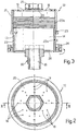
- the damping system 1 comprises at least one Helmholtz resonator 12, which in turn comprises a casing 13 defining inside it ( Figure 3 ) an empty volume 14 having a pre-set size, and a neck 15 for hydraulic connection between the volume 14 and the combustion chamber 4.
- the neck 15 is connected to one side of the combustion chamber 4 at a distance from the front upstream portion 8 thereof provided with the burner or burners 7.
- the damping system comprises a plurality of Helmholtz resonators 12 (only one of which is illustrated for reasons of simplicity and which, in what follows, will be indicated more briefly only as “resonators 12”), which are identical to one another and are mounted circumferentially in a ring in cantilever fashion on the annular body 10, with the respective necks 15 hydraulically connected to the downstream portion 5 of the combustion chamber 4.
- the resonators 12 are mounted in positions that are asymmetrical with respect to one another, both in the circumferential direction and in the axial direction, with reference to the axis of symmetry A.
- the resonators 12 are housed within a case 16, known as "air chamber” or “air case” and illustrated only partially and schematically in Figure 1 , for delivery of air for supporting combustion.
- the air case 16 is set outside the annular body 10 and is shaped so as to be designed to feed air for supporting combustion directly to each burner 7, through the annular element 11.
- each resonator 12 has a cylindrical symmetry and are arranged with respective axes of symmetry thereof (in the case in point illustrated as coinciding with one another and designated by B in Figure 1 ) parallel to one another and oriented to form in the longitudinal section of Figure 1 , a pre-set angle a, preferably substantially of 90°, with the direction of flow 6 of burnt gases that, in use, traverse the combustion chamber 4. This coincides with the direction of orientation of the axis of symmetry of each burner 7, designated by C in Figure 1 .
- the casing 13 of the resonators 12 comprises means for delivery of a cooling fluid, in the case in point consisting of a plurality of holes 18 of pre-set diameter made through the casing 13 and designed to enable passage of (a small) part of the air for supporting combustion directly from the delivery air case 16 towards the combustion chamber 4 through the pre-set volume 14 and the neck 15 of each of the resonators 12.
- the holes 18 are made only through an end plate 20 of the casing 13, facing in use the side opposite to the combustion chamber 4, and are arranged in positions that are mutually asymmetrical, as may be clearly seen in Figure 2 .
- the casing 13 of each of the resonators 12 comprises means for selectively varying the pre-set volume 14 within a pre-set range.
- Said means for selectively varying the pre-set volume 14 of each resonator 12 consist of a particular structure of the casing 13 of the resonators 12, which comprises two cup-shaped tubular bodies 21, 22, which are mounted in a telescopic way co-axially on one another ( Figure 3 ), with respective concavities facing one another, by means of a threaded coupling 23.
- a threaded ring-nut 24 is coupled outside on the tubular body 22 of smaller diameter, which, in the non-limiting case illustrated here, is the one set facing, in use, the body 10 and which is consequently provided, in a single piece, with the neck 15 and is provided on the outside with a male part 23a of the threaded coupling 23.
- the threaded ring-nut 24 is designed, in use, to bear axially upon the tubular body 21 of larger diameter, which can be screwed outside on the tubular body 22, thanks to a female part 23b of the threaded coupling 23, on the side opposite to the combustion chamber 4.
- each resonator 12 enables in use, in particular during the step of starting of the gas turbine and of the corresponding plant, calibration of the natural frequency of the resonator, which can thus be tuned to the natural frequencies of the combustor 2 that are to be dampened.
- said natural frequency is determined by the size of the volume 14, as well as by the number, diameter and length of the necks, number and size of the holes 18, and by the mean temperature of the gas present in the volumes 14 and in the necks 15, which is a function also of the type of fuel used for supplying the gas turbine.
- the holes 18 can have diameters of between 1.5 mm and 4.5 mm and must be present in a number such as to enable a good cooling of the resonators 12, without altering the fluid-dynamics of cooling of the refractory element present in the combustion chamber 4.
- the outermost tubular element 21, fixed to the plate 20 is provided, in a single piece, on its top end portion, with a nut 25, which has the function of tightening the tubular element 21 against the ring-nut 24, at the pre-set distance.
- the ring-nut 24 is screwed onto the male part 23a of the threaded coupling 23 so as to force connection thereof and to serve as a locknut.
- the necks 15 are mounted in use so as to present their own outlet ends inside the internal volume of the combustion chamber 4, in the case in point of the downstream portion 5 thereof. They can extend ( Figure 3 , part illustrated hatched), in some cases, within the pre-set volume 14 delimited by the coupled tubular elements 21, 22 and, hence, beyond a plate 26 ( Figure 3 ) of the tubular element 22 which carries, integral in one piece, the respective neck 15. Said configuration is adopted in order to increase the resonant mass, given the same overall dimensions along the axis B of the resonator.
- the end of the neck 15 that impinges upon the plate 26 at the base of the pipe is provided with means for coupling to the body 10, for example projections or else a threaded coupling 30.
- the resonators by their very nature, function most efficiently when they are set in the proximity of the areas with maximum acoustic pressure. However, the angular position of said areas is not exactly foreseeable in a simple way, in so far as the combustion chamber has an axial symmetry.
- Said angular position is moreover caused by the small constructional differences of the burners.
- the axial position of the peaks of acoustic pressure is located in an area corresponding to the area of transition, where the combustion reaction is completed, but can be determined only empirically, using a certain number of dynamic-pressure gauges, or else constructed theoretically using finite-element or boundary-element programs.
- the resonators must be positioned in an adequate number along the circumference of the combustion chamber and, preferably, their mutual arrangement must not present axial symmetry. They must moreover be arranged in a position corresponding to the downstream portion of the combustion chamber or in any case in a position corresponding to the side thereof at a greater distance from the burners.
- a data-acquisition system was installed, capable of storing the static and dynamic synchronized data and of performing calculation of Fourier transform (FFT) of the signals for dynamic pressure.
- FFT Fourier transform
- thermo-acoustic limits corresponding to different boundary conditions. Then, a set of Helmholtz resonators was installed, the resonators being spaced in an axial and circumferential direction, and the thermo-acoustic limits were studied again, using the same boundary conditions and varying the internal volume of the resonator in order to regulate the dampened frequencies.
- a large data bank is available, containing the results of the tests.
- thermo-acoustic instability was then varied. These parameters were, basically, the flow of air for supporting combustion and the flow of fuel.
Landscapes
- Engineering & Computer Science (AREA)
- Chemical & Material Sciences (AREA)
- Combustion & Propulsion (AREA)
- Mechanical Engineering (AREA)
- General Engineering & Computer Science (AREA)
Claims (7)
- Brennerkammervorrichtung (2) für eine Gasturbine, wobei die Brennkammervorrichtung ein System (1) zur Dämpfung der thermoakustischen Instabilität umfasst, mindestens eine Brennkammer (4) und mindestens einen zu der Brennkammer gehörigen Brenner (7), der in einer Position angeordnet ist, die einem anströmseitigen vorderen Bereich (8) der Brennkammer entspricht; wobei das Dämpfungssystem (1) mindestens einen Helmholtz-Resonator (12) umfasst, der wiederum ein Gehäuse (13) umfasst, das in seinem Inneren ein vorbestimmtes Volumen (14) abgrenzt, sowie einen Hals (15) für die hydraulische Verbindung zwischen dem vorbestimmten Volumen (14) und der Brennkammer (4), wobei der Hals (15) beabstandet von dem mit dem Brenner (7) versehenen, anströmseitigen vorderen Bereich (8) mit einer Seite der Brennkammer (4) verbunden ist; wobei die Brennkammer (4) eine Ringbrennkammer ist und der mindestens eine Resonator (12) in einer Umfangsposition um die Brennkammer angeordnet und in einem Luftbehälter (16) untergebracht ist, der dazu bestimmt ist, Luft zur Unterstützung der Verbrennung zuzuführen, und der außenseitig eines Ringkörpers (10) angeordnet ist, welcher die Brennkammer begrenzt; wobei das Gehäuse (13) und der Hals (15) des mindestens einen Resonators eine zylindrische Symmetrie aufweisen und so angeordnet sind, dass ihre jeweiligen Symmetrieachsen (B) parallel zueinander verlaufen, und so ausgerichtet sind, dass sie einen vorbestimmten Winkel mit einer Strömungsrichtung (6) der Verbrennungsgase bilden, welche die Brennkammer durchqueren; wobei das Dämpfungssystem (1) mehr als einen der Helmholtz-Resonatoren (12) umfasst und die Brennkammervorrichtung (2) dadurch gekennzeichnet ist, dass sie mehr als einen der Brenner (7) umfasst und dass die Resonatoren (12) umlaufend in einem Ring, in freitragender Weise an dem die Brennkammer (4) begrenzenden Ringkörper (10) angeordnet sind, und zwar sowohl in einer Umfangsrichtung als auch in der axialen Richtung in Bezug auf eine Symmetrieachse (A) der Ringbrennkammer in zueinander asymmetrischen Positionen, wobei die jeweiligen Hälse (15) mit einem abströmseitigen Abschnitt (5) der Brennkammer hydraulisch verbunden sind.
- Brennkammervorrichtung nach Anspruch 1, dadurch gekennzeichnet, dass das Gehäuse (13) des Resonators Vorrichtungen (18) zur Zuführung einer Kühlflüssigkeit umfasst.
- Brennkammervorrichtung nach Anspruch 2, dadurch gekennzeichnet, dass die Vorrichtungen zur Zuführung einer Kühlflüssigkeit aus einer Vielzahl von Öffnungen (18) mit einem vorbestimmten Durchmesser bestehen, die in dem Gehäuse (13) des Resonators ausgebildet und dafür ausgelegt sind, dass ein Teil der Luft zur Unterstützung der Verbrennung direkt durch das vorbestimmte Volumen und den Hals des Resonators (12) in Richtung der Brennkammer (4) strömen kann.
- Brennkammervorrichtung nach Anspruch 3, dadurch gekennzeichnet, dass die Öffnungen nur in einer der gegenüberliegenden Seite der Brennkammer (4) zugewandten Endplatte (20) des Gehäuses des Resonators ausgebildet und in zueinander asymmetrischen Positionen angeordnet sind.
- Brennkammervorrichtung nach einem der vorstehenden Ansprüche, dadurch gekennzeichnet, dass das Gehäuse (13) des Resonators Vorrichtungen zur selektiven Veränderung des vorbestimmten Volumens (14) innerhalb eines vorbestimmten Bereichs umfasst.
- Brennkammervorrichtung nach Anspruch 5, dadurch gekennzeichnet, dass das Gehäuse (13) des Resonators zwei becherförmige, röhrenförmige Körper (21, 22) umfasst, die in teleskopischer Weise koaxial zueinander mittels einer Gewindekupplung (23) befestigt sind, wobei die jeweiligen Konkavitäten einander gegenüberliegen; und eine mit einem Gewinde versehene Befestigungsringmutter (24), die außenseitig an einem einstückig mit dem Hals (15) ausgebildeten, ersten (22) der becherförmigen, röhrenförmigen Körper verbunden und dafür ausgelegt ist, axial an einem zweiten (21) der becherförmigen, röhrenförmigen Körper anzuliegen, der an dem ersten dieser Körper an der gegenüberliegenden Seite der Brennkammer außenseitig verschraubt ist.
- Brennkammervorrichtung nach einem der vorstehenden Ansprüche, dadurch gekennzeichnet, dass der vorbestimmte Winkel im Wesentlichen 90° beträgt.
Applications Claiming Priority (2)
| Application Number | Priority Date | Filing Date | Title |
|---|---|---|---|
| IT001013A ITTO20031013A1 (it) | 2003-12-16 | 2003-12-16 | Sistema di smorzamento di instabilita' termoacustiche in un dispositivo combustore per una turbina a gas. |
| PCT/EP2004/053524 WO2005059441A1 (en) | 2003-12-16 | 2004-12-15 | A system for damping thermo-acoustic instability in a combustor device for a gas turbine |
Publications (2)
| Publication Number | Publication Date |
|---|---|
| EP1709366A1 EP1709366A1 (de) | 2006-10-11 |
| EP1709366B1 true EP1709366B1 (de) | 2018-08-22 |
Family
ID=34685653
Family Applications (1)
| Application Number | Title | Priority Date | Filing Date |
|---|---|---|---|
| EP04804871.4A Expired - Lifetime EP1709366B1 (de) | 2003-12-16 | 2004-12-15 | Brennkammervorrichtung für eine gasturbine mit einem system zum dämpfen von thermo-akustischer instabilität |
Country Status (4)
| Country | Link |
|---|---|
| US (1) | US7661267B2 (de) |
| EP (1) | EP1709366B1 (de) |
| IT (1) | ITTO20031013A1 (de) |
| WO (1) | WO2005059441A1 (de) |
Families Citing this family (42)
| Publication number | Priority date | Publication date | Assignee | Title |
|---|---|---|---|---|
| GB0610800D0 (en) * | 2006-06-01 | 2006-07-12 | Rolls Royce Plc | Combustion chamber for a gas turbine engine |
| JP2010515850A (ja) * | 2007-01-04 | 2010-05-13 | アンサルド エネルジア エス.ピー.エー. | ガスタービンブレード・インサート用スペーサ |
| GB0823085D0 (en) * | 2008-12-19 | 2009-01-28 | Rolls Royce Plc | Combustor Rumble |
| US8567197B2 (en) * | 2008-12-31 | 2013-10-29 | General Electric Company | Acoustic damper |
| US8789372B2 (en) * | 2009-07-08 | 2014-07-29 | General Electric Company | Injector with integrated resonator |
| EP2295864B1 (de) * | 2009-08-31 | 2012-11-14 | Alstom Technology Ltd | Verbrennungsvorrichtung einer Gasturbine |
| EP2299177A1 (de) * | 2009-09-21 | 2011-03-23 | Alstom Technology Ltd | Gasturbinenbrennkammer |
| EP2302302A1 (de) * | 2009-09-23 | 2011-03-30 | Siemens Aktiengesellschaft | Helmholtz-Resonator für Gasturbinenbrennkammern |
| EP2397761B1 (de) | 2010-06-16 | 2021-10-06 | Ansaldo Energia Switzerland AG | Helmholtz-Dämpfer |
| EP2397760B1 (de) | 2010-06-16 | 2020-11-18 | Ansaldo Energia IP UK Limited | Dämpfungsanordnung und Verfahren zu deren Entwurf |
| US9127837B2 (en) * | 2010-06-22 | 2015-09-08 | Carrier Corporation | Low pressure drop, low NOx, induced draft gas heaters |
| US8973365B2 (en) * | 2010-10-29 | 2015-03-10 | Solar Turbines Incorporated | Gas turbine combustor with mounting for Helmholtz resonators |
| US8572981B2 (en) | 2010-11-08 | 2013-11-05 | General Electric Company | Self-oscillating fuel injection jets |
| DE202011004521U1 (de) | 2011-03-29 | 2011-06-09 | Alstom Technology Ltd. | Gasturbine und Ansaugkrümmer |
| US9341375B2 (en) | 2011-07-22 | 2016-05-17 | General Electric Company | System for damping oscillations in a turbine combustor |
| US8469141B2 (en) | 2011-08-10 | 2013-06-25 | General Electric Company | Acoustic damping device for use in gas turbine engine |
| US8966903B2 (en) | 2011-08-17 | 2015-03-03 | General Electric Company | Combustor resonator with non-uniform resonator passages |
| US9188340B2 (en) * | 2011-11-18 | 2015-11-17 | General Electric Company | Gas turbine combustor endcover with adjustable flow restrictor and related method |
| US20130255260A1 (en) * | 2012-03-29 | 2013-10-03 | Solar Turbines Inc. | Resonance damper for damping acoustic oscillations from combustor |
| US20130283799A1 (en) * | 2012-04-25 | 2013-10-31 | Solar Turbines Inc. | Resonance damper for damping acoustic oscillations from combustor |
| EP2735796B1 (de) * | 2012-11-23 | 2020-01-01 | Ansaldo Energia IP UK Limited | WAND EINER HEIßGASDURCHGANGSKOMPONENTE EINER GASTURBINE UND VERFAHREN ZUM VERSTÄRKEN DES BETRIEBSVERHALTENS EINER GASTURBINE |
| US9422867B2 (en) | 2013-02-06 | 2016-08-23 | General Electric Company | Variable volume combustor with center hub fuel staging |
| US9447975B2 (en) | 2013-02-06 | 2016-09-20 | General Electric Company | Variable volume combustor with aerodynamic fuel flanges for nozzle mounting |
| US9587562B2 (en) | 2013-02-06 | 2017-03-07 | General Electric Company | Variable volume combustor with aerodynamic support struts |
| US9441544B2 (en) | 2013-02-06 | 2016-09-13 | General Electric Company | Variable volume combustor with nested fuel manifold system |
| US9689572B2 (en) | 2013-02-06 | 2017-06-27 | General Electric Company | Variable volume combustor with a conical liner support |
| US9435539B2 (en) | 2013-02-06 | 2016-09-06 | General Electric Company | Variable volume combustor with pre-nozzle fuel injection system |
| US9562687B2 (en) | 2013-02-06 | 2017-02-07 | General Electric Company | Variable volume combustor with an air bypass system |
| US9546598B2 (en) | 2013-02-06 | 2017-01-17 | General Electric Company | Variable volume combustor |
| US10088165B2 (en) * | 2015-04-07 | 2018-10-02 | General Electric Company | System and method for tuning resonators |
| WO2014133645A2 (en) | 2013-02-20 | 2014-09-04 | Rolls-Royce North American Technologies Inc. | Gas turbine engine having configurable bypass passage |
| US20140245746A1 (en) * | 2013-03-04 | 2014-09-04 | General Electric Company | Combustion arrangement and method of reducing pressure fluctuations of a combustion arrangement |
| EP2816288B1 (de) | 2013-05-24 | 2019-09-04 | Ansaldo Energia IP UK Limited | Dämpfer für Gasturbinenbrennkammer mit einem Schwingungsdämpfer |
| EP2963345B1 (de) * | 2014-06-30 | 2018-09-19 | Ansaldo Energia Switzerland AG | Dämpfer für Gasturbine |
| WO2016039725A1 (en) * | 2014-09-09 | 2016-03-17 | Siemens Aktiengesellschaft | Acoustic damping system for a combustor of a gas turbine engine |
| US10267523B2 (en) * | 2014-09-15 | 2019-04-23 | Ansaldo Energia Ip Uk Limited | Combustor dome damper system |
| CN107002999A (zh) * | 2014-12-01 | 2017-08-01 | 西门子公司 | 用于燃气涡轮发动机的具有可互换计量管的共振器 |
| US10197275B2 (en) * | 2016-05-03 | 2019-02-05 | General Electric Company | High frequency acoustic damper for combustor liners |
| US20180313540A1 (en) * | 2017-05-01 | 2018-11-01 | General Electric Company | Acoustic Damper for Gas Turbine Engine Combustors |
| EP3418637B1 (de) * | 2017-06-20 | 2020-04-22 | General Electric Technology GmbH | Frequenzvariable helmholtz-dämpfer |
| US12134986B1 (en) * | 2024-01-23 | 2024-11-05 | General Electric Company | Acoustic damping device |
| US12366203B1 (en) | 2024-05-15 | 2025-07-22 | General Electric Company | Turbine engine having a multicavity damper |
Family Cites Families (10)
| Publication number | Priority date | Publication date | Assignee | Title |
|---|---|---|---|---|
| US2807931A (en) | 1951-06-16 | 1957-10-01 | Jr Albert G Bodine | Control of combustion instability in jet engines |
| JPS5114550A (ja) | 1974-07-27 | 1976-02-05 | Tokico Ltd | Shoonki |
| EP0597138B1 (de) * | 1992-11-09 | 1997-07-16 | Asea Brown Boveri AG | Gasturbinen-Brennkammer |
| DE4414232A1 (de) | 1994-04-23 | 1995-10-26 | Abb Management Ag | Vorrichtung zur Dämpfung von thermoakustischen Schwingungen in einer Brennkammer |
| US6464489B1 (en) * | 1997-11-24 | 2002-10-15 | Alstom | Method and apparatus for controlling thermoacoustic vibrations in a combustion system |
| DE19851636A1 (de) * | 1998-11-10 | 2000-05-11 | Asea Brown Boveri | Dämpfungsvorrichtung zur Reduzierung der Schwingungsamplitude akustischer Wellen für einen Brenner |
| US6530221B1 (en) * | 2000-09-21 | 2003-03-11 | Siemens Westinghouse Power Corporation | Modular resonators for suppressing combustion instabilities in gas turbine power plants |
| EP1213538B1 (de) * | 2000-12-08 | 2006-09-06 | Alstom Technology Ltd | Abgassystem mit Helmholtz-Resonator |
| EP1423645B1 (de) | 2001-09-07 | 2008-10-08 | Alstom Technology Ltd | Dämpfungsanordnung zur reduzierung von brennkammerpulsationen in einer gasturbinenanlage |
| GB2396687A (en) * | 2002-12-23 | 2004-06-30 | Rolls Royce Plc | Helmholtz resonator for combustion chamber use |
-
2003
- 2003-12-16 IT IT001013A patent/ITTO20031013A1/it unknown
-
2004
- 2004-12-15 WO PCT/EP2004/053524 patent/WO2005059441A1/en not_active Ceased
- 2004-12-15 US US10/596,497 patent/US7661267B2/en not_active Expired - Fee Related
- 2004-12-15 EP EP04804871.4A patent/EP1709366B1/de not_active Expired - Lifetime
Non-Patent Citations (1)
| Title |
|---|
| None * |
Also Published As
| Publication number | Publication date |
|---|---|
| US7661267B2 (en) | 2010-02-16 |
| US20080216481A1 (en) | 2008-09-11 |
| EP1709366A1 (de) | 2006-10-11 |
| ITTO20031013A1 (it) | 2005-06-17 |
| WO2005059441A1 (en) | 2005-06-30 |
Similar Documents
| Publication | Publication Date | Title |
|---|---|---|
| EP1709366B1 (de) | Brennkammervorrichtung für eine gasturbine mit einem system zum dämpfen von thermo-akustischer instabilität | |
| RU2568030C2 (ru) | Демпфирующее устройство для уменьшения пульсаций камеры сгорания | |
| EP1669670B1 (de) | Helmholtzresonator für eine Brennkammer eines Gasturbinentriebwerks | |
| EP1962018B1 (de) | Brennkammer für einen Gasturbinenmotor | |
| EP2559946B1 (de) | System und Verfahren zur Verringerung der Verbrennungsdynamik in einem Brennkammer | |
| EP2865948B1 (de) | Gasturbinenbrennkammer mit Viertelwellen-Dämpfer | |
| US20070125089A1 (en) | Method of suppressing combustion instabilities using a resonator adopting counter-bored holes | |
| US8869533B2 (en) | Combustion system for a gas turbine comprising a resonator | |
| US20070119147A1 (en) | Active combustion control system for gas turbine engines | |
| JP4429730B2 (ja) | ガスタービン | |
| JPH0694227A (ja) | 二次バーナ | |
| WO2004097300A1 (en) | Noise reducing combustor | |
| CN104595928B (zh) | 扩散燃烧室声学火焰筒 | |
| JP2012508864A (ja) | 多重チューブ、環状多筒形パルスデトネーション燃焼器ベースのエンジン | |
| US11686474B2 (en) | Damper for swirl-cup combustors | |
| WO2014173660A1 (en) | Combustion system of a flow engine and method for determining a dimension of a resonator cavity | |
| JP2012117807A (ja) | 広帯域周波数応答の調整可能な共振器 | |
| EP2522910B1 (de) | Brennkammergehäuse zur Abschwächung der Verbrennungsdynamik | |
| CN105452773B (zh) | 用于阻尼声音的设备和方法 | |
| EP2851618A1 (de) | Verbrennungssystem einer Strömungsmaschine | |
| EP3037725B1 (de) | Mischer zur Vermischung einer Verdünnungsluft mit einem Heißgasstrom | |
| EP4028694B1 (de) | System für akustische dämpfer mit mehreren volumina in einer brennkammerfrontplatte | |
| EP1557609B1 (de) | Vorrichtung und Verfahren zur Dämpfung von thermoakustischen Schwingungen in einer Brennkammer | |
| CN115371083A (zh) | 被动燃料耦合动力学缓解装置 | |
| CN107869733B (zh) | 用于燃气涡轮筒形燃烧器的环形亥姆霍兹阻尼器 |
Legal Events
| Date | Code | Title | Description |
|---|---|---|---|
| PUAI | Public reference made under article 153(3) epc to a published international application that has entered the european phase |
Free format text: ORIGINAL CODE: 0009012 |
|
| 17P | Request for examination filed |
Effective date: 20060703 |
|
| AK | Designated contracting states |
Kind code of ref document: A1 Designated state(s): AT BE BG CH CY CZ DE DK EE ES FI FR GB GR HU IE IS IT LI LT LU MC NL PL PT RO SE SI SK TR |
|
| DAX | Request for extension of the european patent (deleted) | ||
| 17Q | First examination report despatched |
Effective date: 20130409 |
|
| REG | Reference to a national code |
Ref country code: DE Ref legal event code: R079 Ref document number: 602004053090 Country of ref document: DE Free format text: PREVIOUS MAIN CLASS: F23M0013000000 Ipc: F23R0003500000 |
|
| GRAP | Despatch of communication of intention to grant a patent |
Free format text: ORIGINAL CODE: EPIDOSNIGR1 |
|
| RIC1 | Information provided on ipc code assigned before grant |
Ipc: F23M 20/00 20140101ALI20180215BHEP Ipc: F23R 3/50 20060101AFI20180215BHEP |
|
| INTG | Intention to grant announced |
Effective date: 20180308 |
|
| GRAS | Grant fee paid |
Free format text: ORIGINAL CODE: EPIDOSNIGR3 |
|
| GRAA | (expected) grant |
Free format text: ORIGINAL CODE: 0009210 |
|
| AK | Designated contracting states |
Kind code of ref document: B1 Designated state(s): AT BE BG CH CY CZ DE DK EE ES FI FR GB GR HU IE IS IT LI LT LU MC NL PL PT RO SE SI SK TR |
|
| REG | Reference to a national code |
Ref country code: GB Ref legal event code: FG4D |
|
| REG | Reference to a national code |
Ref country code: CH Ref legal event code: EP |
|
| REG | Reference to a national code |
Ref country code: DE Ref legal event code: R096 Ref document number: 602004053090 Country of ref document: DE |
|
| REG | Reference to a national code |
Ref country code: AT Ref legal event code: REF Ref document number: 1032959 Country of ref document: AT Kind code of ref document: T Effective date: 20180915 |
|
| REG | Reference to a national code |
Ref country code: IE Ref legal event code: FG4D |
|
| REG | Reference to a national code |
Ref country code: NL Ref legal event code: MP Effective date: 20180822 |
|
| REG | Reference to a national code |
Ref country code: LT Ref legal event code: MG4D |
|
| PG25 | Lapsed in a contracting state [announced via postgrant information from national office to epo] |
Ref country code: SE Free format text: LAPSE BECAUSE OF FAILURE TO SUBMIT A TRANSLATION OF THE DESCRIPTION OR TO PAY THE FEE WITHIN THE PRESCRIBED TIME-LIMIT Effective date: 20180822 Ref country code: BG Free format text: LAPSE BECAUSE OF FAILURE TO SUBMIT A TRANSLATION OF THE DESCRIPTION OR TO PAY THE FEE WITHIN THE PRESCRIBED TIME-LIMIT Effective date: 20181122 Ref country code: IS Free format text: LAPSE BECAUSE OF FAILURE TO SUBMIT A TRANSLATION OF THE DESCRIPTION OR TO PAY THE FEE WITHIN THE PRESCRIBED TIME-LIMIT Effective date: 20181222 Ref country code: GR Free format text: LAPSE BECAUSE OF FAILURE TO SUBMIT A TRANSLATION OF THE DESCRIPTION OR TO PAY THE FEE WITHIN THE PRESCRIBED TIME-LIMIT Effective date: 20181123 Ref country code: FI Free format text: LAPSE BECAUSE OF FAILURE TO SUBMIT A TRANSLATION OF THE DESCRIPTION OR TO PAY THE FEE WITHIN THE PRESCRIBED TIME-LIMIT Effective date: 20180822 Ref country code: NL Free format text: LAPSE BECAUSE OF FAILURE TO SUBMIT A TRANSLATION OF THE DESCRIPTION OR TO PAY THE FEE WITHIN THE PRESCRIBED TIME-LIMIT Effective date: 20180822 Ref country code: LT Free format text: LAPSE BECAUSE OF FAILURE TO SUBMIT A TRANSLATION OF THE DESCRIPTION OR TO PAY THE FEE WITHIN THE PRESCRIBED TIME-LIMIT Effective date: 20180822 |
|
| REG | Reference to a national code |
Ref country code: AT Ref legal event code: MK05 Ref document number: 1032959 Country of ref document: AT Kind code of ref document: T Effective date: 20180822 |
|
| PG25 | Lapsed in a contracting state [announced via postgrant information from national office to epo] |
Ref country code: ES Free format text: LAPSE BECAUSE OF FAILURE TO SUBMIT A TRANSLATION OF THE DESCRIPTION OR TO PAY THE FEE WITHIN THE PRESCRIBED TIME-LIMIT Effective date: 20180822 |
|
| PG25 | Lapsed in a contracting state [announced via postgrant information from national office to epo] |
Ref country code: EE Free format text: LAPSE BECAUSE OF FAILURE TO SUBMIT A TRANSLATION OF THE DESCRIPTION OR TO PAY THE FEE WITHIN THE PRESCRIBED TIME-LIMIT Effective date: 20180822 Ref country code: PL Free format text: LAPSE BECAUSE OF FAILURE TO SUBMIT A TRANSLATION OF THE DESCRIPTION OR TO PAY THE FEE WITHIN THE PRESCRIBED TIME-LIMIT Effective date: 20180822 Ref country code: CZ Free format text: LAPSE BECAUSE OF FAILURE TO SUBMIT A TRANSLATION OF THE DESCRIPTION OR TO PAY THE FEE WITHIN THE PRESCRIBED TIME-LIMIT Effective date: 20180822 Ref country code: RO Free format text: LAPSE BECAUSE OF FAILURE TO SUBMIT A TRANSLATION OF THE DESCRIPTION OR TO PAY THE FEE WITHIN THE PRESCRIBED TIME-LIMIT Effective date: 20180822 Ref country code: AT Free format text: LAPSE BECAUSE OF FAILURE TO SUBMIT A TRANSLATION OF THE DESCRIPTION OR TO PAY THE FEE WITHIN THE PRESCRIBED TIME-LIMIT Effective date: 20180822 |
|
| REG | Reference to a national code |
Ref country code: DE Ref legal event code: R097 Ref document number: 602004053090 Country of ref document: DE |
|
| PG25 | Lapsed in a contracting state [announced via postgrant information from national office to epo] |
Ref country code: SK Free format text: LAPSE BECAUSE OF FAILURE TO SUBMIT A TRANSLATION OF THE DESCRIPTION OR TO PAY THE FEE WITHIN THE PRESCRIBED TIME-LIMIT Effective date: 20180822 Ref country code: DK Free format text: LAPSE BECAUSE OF FAILURE TO SUBMIT A TRANSLATION OF THE DESCRIPTION OR TO PAY THE FEE WITHIN THE PRESCRIBED TIME-LIMIT Effective date: 20180822 |
|
| PLBE | No opposition filed within time limit |
Free format text: ORIGINAL CODE: 0009261 |
|
| STAA | Information on the status of an ep patent application or granted ep patent |
Free format text: STATUS: NO OPPOSITION FILED WITHIN TIME LIMIT |
|
| 26N | No opposition filed |
Effective date: 20190523 |
|
| REG | Reference to a national code |
Ref country code: CH Ref legal event code: PL |
|
| GBPC | Gb: european patent ceased through non-payment of renewal fee |
Effective date: 20181215 |
|
| PG25 | Lapsed in a contracting state [announced via postgrant information from national office to epo] |
Ref country code: MC Free format text: LAPSE BECAUSE OF FAILURE TO SUBMIT A TRANSLATION OF THE DESCRIPTION OR TO PAY THE FEE WITHIN THE PRESCRIBED TIME-LIMIT Effective date: 20180822 Ref country code: SI Free format text: LAPSE BECAUSE OF FAILURE TO SUBMIT A TRANSLATION OF THE DESCRIPTION OR TO PAY THE FEE WITHIN THE PRESCRIBED TIME-LIMIT Effective date: 20180822 Ref country code: LU Free format text: LAPSE BECAUSE OF NON-PAYMENT OF DUE FEES Effective date: 20181215 |
|
| REG | Reference to a national code |
Ref country code: IE Ref legal event code: MM4A |
|
| REG | Reference to a national code |
Ref country code: BE Ref legal event code: MM Effective date: 20181231 |
|
| PG25 | Lapsed in a contracting state [announced via postgrant information from national office to epo] |
Ref country code: FR Free format text: LAPSE BECAUSE OF NON-PAYMENT OF DUE FEES Effective date: 20181231 Ref country code: IE Free format text: LAPSE BECAUSE OF NON-PAYMENT OF DUE FEES Effective date: 20181215 |
|
| PG25 | Lapsed in a contracting state [announced via postgrant information from national office to epo] |
Ref country code: BE Free format text: LAPSE BECAUSE OF NON-PAYMENT OF DUE FEES Effective date: 20181231 |
|
| PG25 | Lapsed in a contracting state [announced via postgrant information from national office to epo] |
Ref country code: LI Free format text: LAPSE BECAUSE OF NON-PAYMENT OF DUE FEES Effective date: 20181231 Ref country code: CH Free format text: LAPSE BECAUSE OF NON-PAYMENT OF DUE FEES Effective date: 20181231 Ref country code: GB Free format text: LAPSE BECAUSE OF NON-PAYMENT OF DUE FEES Effective date: 20181215 |
|
| PG25 | Lapsed in a contracting state [announced via postgrant information from national office to epo] |
Ref country code: TR Free format text: LAPSE BECAUSE OF FAILURE TO SUBMIT A TRANSLATION OF THE DESCRIPTION OR TO PAY THE FEE WITHIN THE PRESCRIBED TIME-LIMIT Effective date: 20180822 |
|
| PG25 | Lapsed in a contracting state [announced via postgrant information from national office to epo] |
Ref country code: PT Free format text: LAPSE BECAUSE OF FAILURE TO SUBMIT A TRANSLATION OF THE DESCRIPTION OR TO PAY THE FEE WITHIN THE PRESCRIBED TIME-LIMIT Effective date: 20180822 |
|
| PG25 | Lapsed in a contracting state [announced via postgrant information from national office to epo] |
Ref country code: CY Free format text: LAPSE BECAUSE OF FAILURE TO SUBMIT A TRANSLATION OF THE DESCRIPTION OR TO PAY THE FEE WITHIN THE PRESCRIBED TIME-LIMIT Effective date: 20180822 Ref country code: HU Free format text: LAPSE BECAUSE OF FAILURE TO SUBMIT A TRANSLATION OF THE DESCRIPTION OR TO PAY THE FEE WITHIN THE PRESCRIBED TIME-LIMIT; INVALID AB INITIO Effective date: 20041215 |
|
| PGFP | Annual fee paid to national office [announced via postgrant information from national office to epo] |
Ref country code: DE Payment date: 20211210 Year of fee payment: 18 |
|
| PGFP | Annual fee paid to national office [announced via postgrant information from national office to epo] |
Ref country code: IT Payment date: 20211224 Year of fee payment: 18 |
|
| REG | Reference to a national code |
Ref country code: DE Ref legal event code: R119 Ref document number: 602004053090 Country of ref document: DE |
|
| PG25 | Lapsed in a contracting state [announced via postgrant information from national office to epo] |
Ref country code: DE Free format text: LAPSE BECAUSE OF NON-PAYMENT OF DUE FEES Effective date: 20230701 |
|
| PG25 | Lapsed in a contracting state [announced via postgrant information from national office to epo] |
Ref country code: IT Free format text: LAPSE BECAUSE OF NON-PAYMENT OF DUE FEES Effective date: 20221215 |