EP1709256B1 - Marine backhoe dredge - Google Patents
Marine backhoe dredge Download PDFInfo
- Publication number
- EP1709256B1 EP1709256B1 EP05705113.8A EP05705113A EP1709256B1 EP 1709256 B1 EP1709256 B1 EP 1709256B1 EP 05705113 A EP05705113 A EP 05705113A EP 1709256 B1 EP1709256 B1 EP 1709256B1
- Authority
- EP
- European Patent Office
- Prior art keywords
- backhoe
- dredge
- vessel
- bucket
- support structure
- Prior art date
- Legal status (The legal status is an assumption and is not a legal conclusion. Google has not performed a legal analysis and makes no representation as to the accuracy of the status listed.)
- Expired - Lifetime
Links
Images


Classifications
-
- E—FIXED CONSTRUCTIONS
- E02—HYDRAULIC ENGINEERING; FOUNDATIONS; SOIL SHIFTING
- E02F—DREDGING; SOIL-SHIFTING
- E02F5/00—Dredgers or soil-shifting machines for special purposes
- E02F5/28—Dredgers or soil-shifting machines for special purposes for cleaning watercourses or other ways
- E02F5/285—Dredgers or soil-shifting machines for special purposes for cleaning watercourses or other ways with drag buckets or scraper plates
-
- E—FIXED CONSTRUCTIONS
- E02—HYDRAULIC ENGINEERING; FOUNDATIONS; SOIL SHIFTING
- E02F—DREDGING; SOIL-SHIFTING
- E02F5/00—Dredgers or soil-shifting machines for special purposes
- E02F5/006—Dredgers or soil-shifting machines for special purposes adapted for working ground under water not otherwise provided for
-
- E—FIXED CONSTRUCTIONS
- E02—HYDRAULIC ENGINEERING; FOUNDATIONS; SOIL SHIFTING
- E02F—DREDGING; SOIL-SHIFTING
- E02F9/00—Component parts of dredgers or soil-shifting machines, not restricted to one of the kinds covered by groups E02F3/00 - E02F7/00
- E02F9/06—Floating substructures as supports
-
- E—FIXED CONSTRUCTIONS
- E02—HYDRAULIC ENGINEERING; FOUNDATIONS; SOIL SHIFTING
- E02F—DREDGING; SOIL-SHIFTING
- E02F9/00—Component parts of dredgers or soil-shifting machines, not restricted to one of the kinds covered by groups E02F3/00 - E02F7/00
- E02F9/06—Floating substructures as supports
- E02F9/062—Advancing equipment, e.g. spuds for floating dredgers
-
- E—FIXED CONSTRUCTIONS
- E02—HYDRAULIC ENGINEERING; FOUNDATIONS; SOIL SHIFTING
- E02F—DREDGING; SOIL-SHIFTING
- E02F9/00—Component parts of dredgers or soil-shifting machines, not restricted to one of the kinds covered by groups E02F3/00 - E02F7/00
- E02F9/18—Counterweights
Definitions
- the present invention relates to a marine backhoe dredge for excavation and mining applications under water.
- the present invention is directed to a sub-aqueous backhoe dredge which includes a counterbalancing system that increases the hoisting capacity and/or the hoisting speed of the backhoe.
- a variety of hydraulic excavators also called backhoe dredges, are known for hoisting hard in-situ and pretreated materials.
- a backhoe dredge typically includes a rotating frame and an attachment assembly consisting of a mono-block boom, stick and bucket.
- US Patent No. 4,676,052 to Hawk discloses a self-propelled dredge which includes a two-piece boom and sealed bucket for removing silt, muck, and plant growth from the bottom of lakes, and ponds
- US Patent No. 3,086,305 to West discloses a dredge which includes a barge having a crane unit mounted thereon and spuds pivotably mounted to the barge.
- US-A- 6823616 shows a marine backhoe dredger according to the preamble of claim 1.
- Hydraulic excavators were originally used for land operations in which the excavated material was hoisted only through one medium, air.
- marine backhoe dredges are required to hoist excavated material through two media, initially water, then air. Due to well-known principles of buoyancy, a backhoe has a greater hoisting capacity while submerged under water, than it does when hoisting loads in an air-medium Due to this disparity in hoisting capabilities, problems often arise.
- the marine borne backhoe dredge often times hoists an excavated load in the water medium that actually exceeds its hoisting capacity in an air medium. In this regard, the backhoe is not sufficient for hoisting the excavated load when the backhoe emmerges from the water surface into the air medium.
- the invention relates to a marine backhoe dredge, comprising a vessel; a backhoe movably mounted on the vessel, the backhoe including a boom, a stick, and a bucket; wherein each of the boom, stick, and bucket is pivotable and has an independent range of motion and a counterbalancing system to increase hoisting capacity or hoisting speed of the backhoe.
- the counterbalancing system includes a support structure mounted to the vessel, a counterbalance, and one or more cables operatively associated with the support structure, counterbalance and backhoe and being connected to the backhoe and counterbalance.
- each of the boom, stick, and bucket of the backhoe is hydraulically driven by a hydraulic system with independent actuators.
- the backhoe is preferably mounted to the vessel by a pedestal mount, a turntable mount or a track mount.
- the backhoe has a broad range of motion, which includes side-to-side movement, and up-and-dovvn movement.
- the counterbalance is preferably a winch that collects or releases the one or more cables as the backhoe is operated, or a counterweight movably mounted on the vessel to collect or release the cable as the backhoe is operated.
- the support structure can be pivotable and in operative association with the backhoe.
- a preferred support structure is an A-frame assembly that includes at least one tie-back cable attached to the adjustable support structure and anchored to the vessel for stability.
- the at least one tie-back cable is preferably a wire rope having a diameter between about 2,54-7,62 cm (1 to 3 inches) so that the at least one tie-back cable is capable of accommodating a backstay load of between about 200 KIPS.
- the bucket advantageously has a capacity ofbetween about 4-27 m 3 (5 to 35 cubic yards) so that the backhoe dredge has a capacity to mine a channel or trench having a depth of up to about 29,9 m (85 feet).
- a plurality of spuds can be provided to inhibit movement of the vessel during operation of the backhoe.
- the plurality of spuds are operable in the vertical direction with respect to the watercraft, the distal end of the plurality of spuds engaging the bottom or floor of the waterway to be excavated and/or mined by the backhoe dredge.
- At least three spuds are provided in operative association such that at least one spud is maintained in a fixed position while the backhoe is operating, and at least one spud is configured to stabilize the vessel in one position but allow advancing of the vessel in another position.
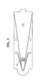
- FIG 4A is a top view of the A frame support structure.
- the invention includes a backhoe dredge for dredging heavily compacted materials including but not limited to rock, blasted rock, and clay from the bottom of waterways.
- the backhoe dredge is also used for underwater mining including the deepening and widening or otherwise forming of channels and/or trenches on the floor of the waterway.
- waterway as used herein includes but is not limited to oceans, harbors, seas, lakes, rivers, estuaries, and other bodies of water that can accommodate the size of the backhoe dredge of the invention.
- backhoe refers to an excavator including a movably mounted bucket mounted to the distal end of an extension arm or to a movably mounted stick.
- distal end of an extension arm or to a movably mounted stick.
- shredge refers to any of various machines equipped with scooping or suction devices, and is used to excavate material, to deepen and/or widen waterways, and in underwater mining.
- the backhoe dredge generally comprises a vessel, a hydraulically-driven backhoe movably mounted to the vessel, and a counterbalancing system that increases the hoisting capacity and/or the hoisting speed of the backhoe.
- the term "vessel” as used herein refers to a craft capable of being navigated on water.
- the overall weight of the boom, stick, and bucket is between about 50 to 300 tons.
- the backhoe is movably mounted on the vessel so that it has a free range of motion in the at least two directions.
- the backhoe advantageously includes a boom segment, a stick segment, and a bucket.
- the boom, the stick, and the bucket are each hydraulically-driven, with each having a hydraulic system with independent actuators.
- each of the boom segment, the stick segment, and the bucket have a range of motion in at least two directions.
- the range of motion of each section is independent of the others.
- the counterbalancing system includes an adjustable support structure mounted on the vessel, with one or more cables operatively associated with the adjustable support structure.
- the one or more cables are advantageously connected to a counterbalance that is mounted on the vessel.
- the support structure is adjustable according to the position of the backhoe.
- the one or more cables are operatively attached to support structure, and preferably are one or more wire ropes.
- the adjustable support structure is operatively attached to the boom of the backhoe.
- At least one tie-back cable is utilized to "tie-back" the adjustable support structure such that the adjustable support member forms an angle with the vessel.
- the tie-back cable is attached to the adjustable support structure and to the vessel.
- the counterbalance preferably comprises a winch or a counterweight.
- the counterbalancing structure is a counterweight, it is located in a housing mounted to or upon the vessel.
- the counterbalancing system provides the backhoe dredge with increased hoisting capacity and/or hoisting speed and does not suffer from the limitations imposed by the hydraulic capacity of the vessel.
- the backhoe dredge of the invention is more suitable for hoisting very heavy materials, such as rock, concrete, blasted rock, clay and other heavily compacted materials.
- the backhoe dredge comprises a water craft, a hydraulically-driven backhoe that is movably mounted to the water craft, and a counterbalancing system that increases the hoisting capacity and/or the hoisting speed of the backhoe.
- the backhoe of this aspect of the invention includes an extension arm having an open bucket movably attached to the distal end of the extension arm. The dimensions of the bucket are in the order of about 4-27 m 3 (5 to 35 cubic yards) and the backhoe dredge has a hoisting capacity sufficient to hoist about 7 to 50 tons of dredging material.
- the apparatus presented herein may be used for purposes including dredging or excavating material from the bottom of a waterway; deepening and widening channels; and/or underwater mining.
- the present invention is particularly suited for dredging heavily compacted materials including but not limited to rock, blasted rock, clay, and the like.
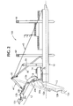
- Fig. 1 an exemplary embodiment of the system in accordance with the invention is shown in Fig. 1 and is designated generally by reference character 100.
- the backhoe dredging system 100 generally includes a vessel 10, a backhoe 12 movably or pivotably mounted onto the vessel, and a counterbalancing system 14 to increase the hoisting capacity and/or the hoisting speed of the backhoe dredge.
- the vessel 10 embodied herein is a water craft capable of being navigated on water.
- the backhoe 12 of the present invention is movably or pivotably mounted on the vessel 10 and includes a boom 12a, a stick 12b , and a bucket 12c. As shown in Figure 1 , the backhoe is pivotably mounted 18 to the vessel by a pedestal mount 25. However, other mounting techniques can also be used including but not limited to a turntable mount, a tracking mount, or any other type of mount that provides the backhoe with a suitable range of motion for excavating, mining, and channel-forming or trench-forming applications. Preferably, the backhoe is mounted to the vessel by a turntable.
- stick 12b is movably mounted to the distal end of the boom 12a
- the bucket 12c is movably mounted to the stick 12b.
- each of 12a, 12b, and 12c of the backhoe has an independent range of motion, thus providing a wide range of excavating movement to the backhoe.
- the backhoe includes three sets of hydraulic actuators 20a, 20b, 20c, which correspond to boom 12a, stick 12b, and bucket 12c of the backhoe, respectively.
- Hydraulic actuator 20a hydraulically drives the boom segment of the backhoe
- hydraulic actuator 20b drives the stick segment of the backhoe
- hydraulic actuator 20c drives the bucket segment of the backhoe. Utilization of separate hydraulic actuators for each of the boom 12a, stick 12b, and bucket 12c provides controlled range of motion for each of the boom, stick and bucket of the backhoe.
- the counterbalancing system of the present invention includes an adjustable support structure 30, one or more cables 40, 45 operatively associated with the adjustable support structure , and a counterbalance 50 mounted to the vessel 10.
- the adjustable support structure is preferably an "A-frame" assembly 30 mounted to the vessel 10.
- the marine backhoe dredge affixed to the watercraft has a range of motion depicted in phantom.
- Figure 4A illustrates a support structure, preferably an A-frame assembly 30, which is preferably formed of first and second metal pipes 31, generally of high strength steel, and third and fourth metal pipes 32, also of high strength steel.
- the support structure 30 is pivotably mounted to the vessel 10, and is adjustable in relation to the backhoe position.
- the adjustable support structure 30 is affixed to at least one tie-back cable 45, which is anchored to the vessel 10, as can be seen in Figures 1 , 2 and 3 .
- the at least one tie-back cable 45 is a wire rope having a diameter of about 2,54-7,62 cm (1 to 3 inches).
- the at least one tie-back cable 45 accommodates a backstay load of about 200 KIPS.
- the unit KIPS as used herein refers to a unit of weight equal to 1,000 pounds or 455 kilograms.
- Cable 40 is operatively associated with the support structure 30 and the backhoe 12.
- the cable is operatively associated at an intermediate point 15 on the backhoe, and to a distal point 35 on the support structure 30.
- the support structure 30 and the backhoe 12 preferably include cable attachment means to operatively attach the cable 40 to the support structure 30 and the backhoe 12.
- Cable attachment means include but are not limited to an aperture, ring, pulley, block, drum, or other means capable of receiving cable 40 such as, for example, reeving, winding or wrapping the cable through or around or about the attachment means.
- a counterbalance system 14 is mounted on vessel 10.
- the counterbalance may be a winch 50 as shown in Figure 1 or a counterweight assembly, as shown in Figure 2 .
- the counterweight weight assembly includes a counterweight housed in a tower 55oar other housing as shown in Figure 2 .
- the counterbalance is tightened to support the weight of the boom, stick, bucket, and load.
- the cable is collected or played out as the backhoe is operated using the winch 50 or by vertical counterweight movement in the tower 55.
- the backhoe can lift and move greater amounts of material thus increasing the efficiency of operation of the apparatus. This allows greater bucket sizes to be implemented than if the hydraulic drives are used alone.
- the backhoe dredge includes a plurality of spuds 60 to stabilize the vessel and prevent movement of the vessel during operation of the backhoe dredge.
- the plurality of spuds are independently vertically operable. In operation, the plurality of spuds engage the floor or bed of the waterway so that the vessel is stabilized.
- the construction of the plurality of spuds can include a pointed engaging member to engage the floor of the waterway and become at least partially embedded in the floor of the waterway to help prevent movement of the vessel during operation of the backhoe.
- anchors can be used to help prevent movement of the vessel during operation of the backhoe dredge.
Landscapes
- Engineering & Computer Science (AREA)
- Mining & Mineral Resources (AREA)
- Civil Engineering (AREA)
- General Engineering & Computer Science (AREA)
- Structural Engineering (AREA)
- Mechanical Engineering (AREA)
- Earth Drilling (AREA)
- Shovels (AREA)
- Component Parts Of Construction Machinery (AREA)
- Underground Or Underwater Handling Of Building Materials (AREA)
Priority Applications (1)
| Application Number | Priority Date | Filing Date | Title |
|---|---|---|---|
| PL05705113T PL1709256T3 (pl) | 2004-01-15 | 2005-01-07 | Morska pogłębiarka posiębierna |
Applications Claiming Priority (2)
| Application Number | Priority Date | Filing Date | Title |
|---|---|---|---|
| US10/760,096 US7143532B2 (en) | 2004-01-15 | 2004-01-15 | Marine backhoe dredge |
| PCT/US2005/000327 WO2005070049A2 (en) | 2004-01-15 | 2005-01-07 | Marine backhoe dredge |
Publications (3)
| Publication Number | Publication Date |
|---|---|
| EP1709256A2 EP1709256A2 (en) | 2006-10-11 |
| EP1709256A4 EP1709256A4 (en) | 2011-12-28 |
| EP1709256B1 true EP1709256B1 (en) | 2013-09-04 |
Family
ID=34807524
Family Applications (1)
| Application Number | Title | Priority Date | Filing Date |
|---|---|---|---|
| EP05705113.8A Expired - Lifetime EP1709256B1 (en) | 2004-01-15 | 2005-01-07 | Marine backhoe dredge |
Country Status (7)
| Country | Link |
|---|---|
| US (1) | US7143532B2 (pl) |
| EP (1) | EP1709256B1 (pl) |
| DK (1) | DK1709256T3 (pl) |
| ES (1) | ES2438189T3 (pl) |
| PL (1) | PL1709256T3 (pl) |
| PT (1) | PT1709256E (pl) |
| WO (1) | WO2005070049A2 (pl) |
Families Citing this family (12)
| Publication number | Priority date | Publication date | Assignee | Title |
|---|---|---|---|---|
| US20060037550A1 (en) * | 2004-01-30 | 2006-02-23 | May Roy C | Apparatus and method of harvesting shellfish |
| US20100083542A1 (en) * | 2008-10-07 | 2010-04-08 | Powers James M | Remotely operated submerged dredging system |
| CN101864781B (zh) * | 2010-06-02 | 2012-09-19 | 段玉祥 | 清淤采掘机 |
| US8994519B1 (en) * | 2010-07-10 | 2015-03-31 | William Fuchs | Method of controlling a vegetation removal system |
| CA2758915A1 (en) * | 2011-11-17 | 2013-05-17 | Jonathan K. W. Biley | Method and apparatus for harvesting beached seaweed by vacuum |
| USD740330S1 (en) * | 2012-09-12 | 2015-10-06 | Lännen Mce Oy | Dredger |
| USD740331S1 (en) * | 2012-09-12 | 2015-10-06 | Lännen Mce Oy | Dredger |
| CN103352485B (zh) * | 2013-06-26 | 2017-02-01 | 合肥汇众知识产权管理有限公司 | 一种挖泥船行走控制机构及其控制方法 |
| CN104843147A (zh) * | 2014-02-13 | 2015-08-19 | 黑龙江省水利科学研究院 | 钢索导向、定位抽砂船水下开挖系统构成 |
| CN109235519B (zh) * | 2018-09-20 | 2021-06-18 | 东阳市中傲建筑工程有限公司 | 一种水利工程清淤装置 |
| NL2022575B1 (en) * | 2019-02-14 | 2020-08-28 | Ihc Holland Ie Bv | Counterweight Backhoe dredger |
| CN114134953A (zh) * | 2021-12-01 | 2022-03-04 | 华北水利水电大学 | 一种河道淤泥收集装置 |
Family Cites Families (18)
| Publication number | Priority date | Publication date | Assignee | Title |
|---|---|---|---|---|
| US659489A (en) | 1900-06-04 | 1900-10-09 | Ralph R Osgood | Dredge. |
| US776124A (en) | 1904-06-03 | 1904-11-29 | John Warren Dutton | Ditching-machine. |
| US776125A (en) | 1904-09-06 | 1904-11-29 | John Warren Dutton | Ditching-machine. |
| US919498A (en) * | 1908-07-22 | 1909-04-27 | H L Weiser | Excavating-machine. |
| US1047233A (en) * | 1911-10-24 | 1912-12-17 | George W Jackson | Scow for transporting gravel. |
| US1549508A (en) * | 1924-02-19 | 1925-08-11 | Robinson Arthur Wells | Clamshell dredge |
| US1915331A (en) | 1932-04-20 | 1933-06-27 | Neveling Aloys | Spud for dredges |
| US2033883A (en) * | 1935-08-19 | 1936-03-10 | Bucyrus Erie Co | Counterweight for excavators |
| US2271344A (en) | 1940-12-23 | 1942-01-27 | John D Rauch | Reclinable spud construction |
| US2640284A (en) | 1947-08-07 | 1953-06-02 | Fridtjof G Nielsen | Dredge |
| US2569458A (en) * | 1947-11-17 | 1951-10-02 | Bucyrus Eric Company | Front end for excavating machines |
| US2944352A (en) | 1957-10-02 | 1960-07-12 | Ellicott Machine Corp | Portable dredge |
| US3064370A (en) * | 1960-04-29 | 1962-11-20 | Pittsburgh Plate Glass Co | Canal dredge |
| US3086305A (en) | 1961-08-17 | 1963-04-23 | Manitowoc Shipbuilding Inc | Dredge |
| FR2241479B1 (pl) * | 1973-08-22 | 1979-05-11 | Orenstein & Koppel Ag | |
| US4676052A (en) | 1985-09-27 | 1987-06-30 | Hawk James L | Self-propelled dredge |
| US5435083A (en) * | 1994-05-16 | 1995-07-25 | Thompson; John L. | Aquatic weed eradicator |
| US6823616B1 (en) | 2001-07-06 | 2004-11-30 | Boskalis Westminister Inc. | Method of excavating |
-
2004
- 2004-01-15 US US10/760,096 patent/US7143532B2/en not_active Expired - Lifetime
-
2005
- 2005-01-07 ES ES05705113.8T patent/ES2438189T3/es not_active Expired - Lifetime
- 2005-01-07 PL PL05705113T patent/PL1709256T3/pl unknown
- 2005-01-07 DK DK05705113.8T patent/DK1709256T3/da active
- 2005-01-07 PT PT57051138T patent/PT1709256E/pt unknown
- 2005-01-07 EP EP05705113.8A patent/EP1709256B1/en not_active Expired - Lifetime
- 2005-01-07 WO PCT/US2005/000327 patent/WO2005070049A2/en not_active Ceased
Also Published As
| Publication number | Publication date |
|---|---|
| WO2005070049A2 (en) | 2005-08-04 |
| EP1709256A4 (en) | 2011-12-28 |
| EP1709256A2 (en) | 2006-10-11 |
| DK1709256T3 (da) | 2013-10-28 |
| PT1709256E (pt) | 2013-11-25 |
| ES2438189T3 (es) | 2014-01-16 |
| WO2005070049A3 (en) | 2005-11-10 |
| US7143532B2 (en) | 2006-12-05 |
| US20050172521A1 (en) | 2005-08-11 |
| PL1709256T3 (pl) | 2014-03-31 |
Similar Documents
| Publication | Publication Date | Title |
|---|---|---|
| EP1709256B1 (en) | Marine backhoe dredge | |
| CN107724416A (zh) | 一种用于建造水下基础结构及其安装方法 | |
| EP3924559B1 (en) | Counterweight backhoe dredger | |
| CN112429159A (zh) | 一种小型精密施工船 | |
| CN109372047B (zh) | 一种适用于绞吸式挖泥船的三缆定位系统 | |
| US20220381001A1 (en) | Dragline with robotic bucket for dredging and excavating | |
| JP2002147157A (ja) | 水中掘削装置及び水中掘削工法 | |
| JP7186351B2 (ja) | 振動打設式油圧掘削バケットと掘削重機及び浚渫作業船 | |
| CN2217002Y (zh) | 一种液压抓斗偏摆控制装置 | |
| JP2585195B2 (ja) | 水中作業機 | |
| CN106480920A (zh) | 一种桥式自动侧挖式抓斗挖泥船 | |
| CN120099894B (zh) | 一种高桩码头先桩后泥逆序施工方法 | |
| CN216999924U (zh) | 一种船舶定位桩升降装置 | |
| CN208857865U (zh) | 一种反铲挖泥船 | |
| CN109252559B (zh) | 一种应用于绞吸式挖泥船的三缆定位系统 | |
| CN109252560B (zh) | 一种绞吸式挖泥船的三缆定位系统 | |
| KR20250096097A (ko) | 수중 흙막이벽체 | |
| JP2025161678A (ja) | 真空バケット浚渫工法と真空バケット及び真空バケット浚渫船 | |
| CN118407484A (zh) | 一种码头下方疏浚清淤方法 | |
| CN116641431A (zh) | 一种适于高桩码头梁板下全潮位机动定位作业的疏浚方法 | |
| WO2023107676A1 (en) | Submersible drag barge | |
| CN116397591A (zh) | 一种适用于码头后方清淤减载的可移动式导流装置 | |
| EP1605103B1 (en) | Dredging device and apparatus | |
| CN121273130A (zh) | 内河沉管预制干坞的坞口组合体系拆除施工方法 | |
| JPH0623452B2 (ja) | ケーソン底部の掘削装置 |
Legal Events
| Date | Code | Title | Description |
|---|---|---|---|
| PUAI | Public reference made under article 153(3) epc to a published international application that has entered the european phase |
Free format text: ORIGINAL CODE: 0009012 |
|
| 17P | Request for examination filed |
Effective date: 20060713 |
|
| AK | Designated contracting states |
Kind code of ref document: A2 Designated state(s): AT BE BG CH CY CZ DE DK EE ES FI FR GB GR HU IE IS IT LI LT LU MC NL PL PT RO SE SI SK TR |
|
| DAX | Request for extension of the european patent (deleted) | ||
| A4 | Supplementary search report drawn up and despatched |
Effective date: 20111125 |
|
| RIC1 | Information provided on ipc code assigned before grant |
Ipc: E02F 9/06 20060101ALI20111121BHEP Ipc: E02F 9/18 20060101ALI20111121BHEP Ipc: E02F 5/00 20060101ALI20111121BHEP Ipc: E02F 5/28 20060101AFI20111121BHEP |
|
| R17P | Request for examination filed (corrected) |
Effective date: 20060713 |
|
| 17Q | First examination report despatched |
Effective date: 20120322 |
|
| GRAP | Despatch of communication of intention to grant a patent |
Free format text: ORIGINAL CODE: EPIDOSNIGR1 |
|
| GRAS | Grant fee paid |
Free format text: ORIGINAL CODE: EPIDOSNIGR3 |
|
| GRAA | (expected) grant |
Free format text: ORIGINAL CODE: 0009210 |
|
| AK | Designated contracting states |
Kind code of ref document: B1 Designated state(s): AT BE BG CH CY CZ DE DK EE ES FI FR GB GR HU IE IS IT LI LT LU MC NL PL PT RO SE SI SK TR |
|
| REG | Reference to a national code |
Ref country code: GB Ref legal event code: FG4D |
|
| REG | Reference to a national code |
Ref country code: CH Ref legal event code: EP |
|
| REG | Reference to a national code |
Ref country code: AT Ref legal event code: REF Ref document number: 630637 Country of ref document: AT Kind code of ref document: T Effective date: 20130915 |
|
| REG | Reference to a national code |
Ref country code: IE Ref legal event code: FG4D |
|
| REG | Reference to a national code |
Ref country code: DK Ref legal event code: T3 Effective date: 20131022 Ref country code: DK Ref legal event code: T3 |
|
| REG | Reference to a national code |
Ref country code: DE Ref legal event code: R096 Ref document number: 602005041098 Country of ref document: DE Effective date: 20131031 |
|
| REG | Reference to a national code |
Ref country code: PT Ref legal event code: SC4A Free format text: AVAILABILITY OF NATIONAL TRANSLATION Effective date: 20131115 |
|
| REG | Reference to a national code |
Ref country code: NL Ref legal event code: T3 |
|
| REG | Reference to a national code |
Ref country code: SE Ref legal event code: TRGR |
|
| REG | Reference to a national code |
Ref country code: AT Ref legal event code: MK05 Ref document number: 630637 Country of ref document: AT Kind code of ref document: T Effective date: 20130904 |
|
| REG | Reference to a national code |
Ref country code: ES Ref legal event code: FG2A Ref document number: 2438189 Country of ref document: ES Kind code of ref document: T3 Effective date: 20140116 |
|
| PG25 | Lapsed in a contracting state [announced via postgrant information from national office to epo] |
Ref country code: AT Free format text: LAPSE BECAUSE OF FAILURE TO SUBMIT A TRANSLATION OF THE DESCRIPTION OR TO PAY THE FEE WITHIN THE PRESCRIBED TIME-LIMIT Effective date: 20130904 Ref country code: CY Free format text: LAPSE BECAUSE OF FAILURE TO SUBMIT A TRANSLATION OF THE DESCRIPTION OR TO PAY THE FEE WITHIN THE PRESCRIBED TIME-LIMIT Effective date: 20130710 |
|
| PGFP | Annual fee paid to national office [announced via postgrant information from national office to epo] |
Ref country code: IS Payment date: 20131206 Year of fee payment: 10 Ref country code: MC Payment date: 20131211 Year of fee payment: 10 Ref country code: LT Payment date: 20131220 Year of fee payment: 10 |
|
| REG | Reference to a national code |
Ref country code: GR Ref legal event code: EP Ref document number: 20130402543 Country of ref document: GR Effective date: 20140102 |
|
| PG25 | Lapsed in a contracting state [announced via postgrant information from national office to epo] |
Ref country code: SI Free format text: LAPSE BECAUSE OF FAILURE TO SUBMIT A TRANSLATION OF THE DESCRIPTION OR TO PAY THE FEE WITHIN THE PRESCRIBED TIME-LIMIT Effective date: 20130904 |
|
| PGFP | Annual fee paid to national office [announced via postgrant information from national office to epo] |
Ref country code: ES Payment date: 20131211 Year of fee payment: 10 Ref country code: GR Payment date: 20131216 Year of fee payment: 10 |
|
| PG25 | Lapsed in a contracting state [announced via postgrant information from national office to epo] |
Ref country code: CY Free format text: LAPSE BECAUSE OF FAILURE TO SUBMIT A TRANSLATION OF THE DESCRIPTION OR TO PAY THE FEE WITHIN THE PRESCRIBED TIME-LIMIT Effective date: 20130904 |
|
| REG | Reference to a national code |
Ref country code: EE Ref legal event code: FG4A Ref document number: E008980 Country of ref document: EE Effective date: 20131203 |
|
| PG25 | Lapsed in a contracting state [announced via postgrant information from national office to epo] |
Ref country code: RO Free format text: LAPSE BECAUSE OF FAILURE TO SUBMIT A TRANSLATION OF THE DESCRIPTION OR TO PAY THE FEE WITHIN THE PRESCRIBED TIME-LIMIT Effective date: 20130904 Ref country code: SK Free format text: LAPSE BECAUSE OF FAILURE TO SUBMIT A TRANSLATION OF THE DESCRIPTION OR TO PAY THE FEE WITHIN THE PRESCRIBED TIME-LIMIT Effective date: 20130904 |
|
| PGFP | Annual fee paid to national office [announced via postgrant information from national office to epo] |
Ref country code: FI Payment date: 20140110 Year of fee payment: 10 Ref country code: SE Payment date: 20140113 Year of fee payment: 10 Ref country code: EE Payment date: 20131213 Year of fee payment: 10 Ref country code: DE Payment date: 20131231 Year of fee payment: 10 Ref country code: DK Payment date: 20140110 Year of fee payment: 10 Ref country code: CZ Payment date: 20140102 Year of fee payment: 10 |
|
| PGFP | Annual fee paid to national office [announced via postgrant information from national office to epo] |
Ref country code: FR Payment date: 20140108 Year of fee payment: 10 Ref country code: IT Payment date: 20140110 Year of fee payment: 10 Ref country code: TR Payment date: 20140106 Year of fee payment: 10 |
|
| REG | Reference to a national code |
Ref country code: DE Ref legal event code: R097 Ref document number: 602005041098 Country of ref document: DE |
|
| PGFP | Annual fee paid to national office [announced via postgrant information from national office to epo] |
Ref country code: PT Payment date: 20140107 Year of fee payment: 10 |
|
| PLBE | No opposition filed within time limit |
Free format text: ORIGINAL CODE: 0009261 |
|
| STAA | Information on the status of an ep patent application or granted ep patent |
Free format text: STATUS: NO OPPOSITION FILED WITHIN TIME LIMIT |
|
| 26N | No opposition filed |
Effective date: 20140605 |
|
| PG25 | Lapsed in a contracting state [announced via postgrant information from national office to epo] |
Ref country code: LU Free format text: LAPSE BECAUSE OF FAILURE TO SUBMIT A TRANSLATION OF THE DESCRIPTION OR TO PAY THE FEE WITHIN THE PRESCRIBED TIME-LIMIT Effective date: 20140107 |
|
| REG | Reference to a national code |
Ref country code: CH Ref legal event code: PL |
|
| REG | Reference to a national code |
Ref country code: DE Ref legal event code: R097 Ref document number: 602005041098 Country of ref document: DE Effective date: 20140605 |
|
| PGFP | Annual fee paid to national office [announced via postgrant information from national office to epo] |
Ref country code: PL Payment date: 20131227 Year of fee payment: 10 |
|
| PG25 | Lapsed in a contracting state [announced via postgrant information from national office to epo] |
Ref country code: LI Free format text: LAPSE BECAUSE OF NON-PAYMENT OF DUE FEES Effective date: 20140131 Ref country code: CH Free format text: LAPSE BECAUSE OF NON-PAYMENT OF DUE FEES Effective date: 20140131 |
|
| REG | Reference to a national code |
Ref country code: PT Ref legal event code: MM4A Free format text: LAPSE DUE TO NON-PAYMENT OF FEES Effective date: 20150707 |
|
| PG25 | Lapsed in a contracting state [announced via postgrant information from national office to epo] |
Ref country code: CZ Free format text: LAPSE BECAUSE OF NON-PAYMENT OF DUE FEES Effective date: 20150107 |
|
| REG | Reference to a national code |
Ref country code: DE Ref legal event code: R119 Ref document number: 602005041098 Country of ref document: DE |
|
| REG | Reference to a national code |
Ref country code: LT Ref legal event code: MM4D Effective date: 20150107 |
|
| REG | Reference to a national code |
Ref country code: DK Ref legal event code: EBP Effective date: 20150131 |
|
| REG | Reference to a national code |
Ref country code: SE Ref legal event code: EUG |
|
| REG | Reference to a national code |
Ref country code: EE Ref legal event code: MM4A Ref document number: E008980 Country of ref document: EE Effective date: 20150131 |
|
| PG25 | Lapsed in a contracting state [announced via postgrant information from national office to epo] |
Ref country code: MC Free format text: LAPSE BECAUSE OF NON-PAYMENT OF DUE FEES Effective date: 20150202 |
|
| REG | Reference to a national code |
Ref country code: GR Ref legal event code: ML Ref document number: 20130402543 Country of ref document: GR Effective date: 20150805 |
|
| PG25 | Lapsed in a contracting state [announced via postgrant information from national office to epo] |
Ref country code: EE Free format text: LAPSE BECAUSE OF NON-PAYMENT OF DUE FEES Effective date: 20150131 Ref country code: PT Free format text: LAPSE BECAUSE OF NON-PAYMENT OF DUE FEES Effective date: 20150707 Ref country code: DE Free format text: LAPSE BECAUSE OF NON-PAYMENT OF DUE FEES Effective date: 20150801 Ref country code: LT Free format text: LAPSE BECAUSE OF NON-PAYMENT OF DUE FEES Effective date: 20150107 Ref country code: FI Free format text: LAPSE BECAUSE OF NON-PAYMENT OF DUE FEES Effective date: 20150107 |
|
| REG | Reference to a national code |
Ref country code: FR Ref legal event code: ST Effective date: 20150930 |
|
| PG25 | Lapsed in a contracting state [announced via postgrant information from national office to epo] |
Ref country code: SE Free format text: LAPSE BECAUSE OF NON-PAYMENT OF DUE FEES Effective date: 20150108 Ref country code: FR Free format text: LAPSE BECAUSE OF NON-PAYMENT OF DUE FEES Effective date: 20150202 Ref country code: IS Free format text: LAPSE BECAUSE OF FAILURE TO SUBMIT A TRANSLATION OF THE DESCRIPTION OR TO PAY THE FEE WITHIN THE PRESCRIBED TIME-LIMIT Effective date: 20150801 Ref country code: GR Free format text: LAPSE BECAUSE OF NON-PAYMENT OF DUE FEES Effective date: 20150805 |
|
| PG25 | Lapsed in a contracting state [announced via postgrant information from national office to epo] |
Ref country code: IT Free format text: LAPSE BECAUSE OF NON-PAYMENT OF DUE FEES Effective date: 20150107 |
|
| PG25 | Lapsed in a contracting state [announced via postgrant information from national office to epo] |
Ref country code: DK Free format text: LAPSE BECAUSE OF NON-PAYMENT OF DUE FEES Effective date: 20150131 |
|
| REG | Reference to a national code |
Ref country code: ES Ref legal event code: FD2A Effective date: 20160527 |
|
| PG25 | Lapsed in a contracting state [announced via postgrant information from national office to epo] |
Ref country code: BG Free format text: LAPSE BECAUSE OF FAILURE TO SUBMIT A TRANSLATION OF THE DESCRIPTION OR TO PAY THE FEE WITHIN THE PRESCRIBED TIME-LIMIT Effective date: 20130904 Ref country code: PL Free format text: LAPSE BECAUSE OF NON-PAYMENT OF DUE FEES Effective date: 20150107 |
|
| PG25 | Lapsed in a contracting state [announced via postgrant information from national office to epo] |
Ref country code: HU Free format text: LAPSE BECAUSE OF FAILURE TO SUBMIT A TRANSLATION OF THE DESCRIPTION OR TO PAY THE FEE WITHIN THE PRESCRIBED TIME-LIMIT; INVALID AB INITIO Effective date: 20050107 Ref country code: ES Free format text: LAPSE BECAUSE OF NON-PAYMENT OF DUE FEES Effective date: 20150108 |
|
| PG25 | Lapsed in a contracting state [announced via postgrant information from national office to epo] |
Ref country code: TR Free format text: LAPSE BECAUSE OF NON-PAYMENT OF DUE FEES Effective date: 20150107 |
|
| PGFP | Annual fee paid to national office [announced via postgrant information from national office to epo] |
Ref country code: IE Payment date: 20190425 Year of fee payment: 15 |
|
| PGFP | Annual fee paid to national office [announced via postgrant information from national office to epo] |
Ref country code: BE Payment date: 20191217 Year of fee payment: 16 |
|
| PGFP | Annual fee paid to national office [announced via postgrant information from national office to epo] |
Ref country code: NL Payment date: 20200130 Year of fee payment: 16 Ref country code: GB Payment date: 20191230 Year of fee payment: 16 |
|
| PG25 | Lapsed in a contracting state [announced via postgrant information from national office to epo] |
Ref country code: IE Free format text: LAPSE BECAUSE OF NON-PAYMENT OF DUE FEES Effective date: 20200107 |
|
| REG | Reference to a national code |
Ref country code: NL Ref legal event code: MM Effective date: 20210201 |
|
| GBPC | Gb: european patent ceased through non-payment of renewal fee |
Effective date: 20210107 |
|
| REG | Reference to a national code |
Ref country code: BE Ref legal event code: MM Effective date: 20210131 |
|
| PG25 | Lapsed in a contracting state [announced via postgrant information from national office to epo] |
Ref country code: NL Free format text: LAPSE BECAUSE OF NON-PAYMENT OF DUE FEES Effective date: 20210201 |
|
| PG25 | Lapsed in a contracting state [announced via postgrant information from national office to epo] |
Ref country code: GB Free format text: LAPSE BECAUSE OF NON-PAYMENT OF DUE FEES Effective date: 20210107 |
|
| PG25 | Lapsed in a contracting state [announced via postgrant information from national office to epo] |
Ref country code: BE Free format text: LAPSE BECAUSE OF NON-PAYMENT OF DUE FEES Effective date: 20210131 |