EP1708540A2 - Verfahren zur Temperaturmessung bei einem Haushaltsgerät - Google Patents
Verfahren zur Temperaturmessung bei einem Haushaltsgerät Download PDFInfo
- Publication number
- EP1708540A2 EP1708540A2 EP06004577A EP06004577A EP1708540A2 EP 1708540 A2 EP1708540 A2 EP 1708540A2 EP 06004577 A EP06004577 A EP 06004577A EP 06004577 A EP06004577 A EP 06004577A EP 1708540 A2 EP1708540 A2 EP 1708540A2
- Authority
- EP
- European Patent Office
- Prior art keywords
- temperature
- frequency
- surface acoustic
- signal level
- processing unit
- Prior art date
- Legal status (The legal status is an assumption and is not a legal conclusion. Google has not performed a legal analysis and makes no representation as to the accuracy of the status listed.)
- Granted
Links
Images


Classifications
-
- H—ELECTRICITY
- H04—ELECTRIC COMMUNICATION TECHNIQUE
- H04Q—SELECTING
- H04Q9/00—Arrangements in telecontrol or telemetry systems for selectively calling a substation from a main station, in which substation desired apparatus is selected for applying a control signal thereto or for obtaining measured values therefrom
-
- F—MECHANICAL ENGINEERING; LIGHTING; HEATING; WEAPONS; BLASTING
- F24—HEATING; RANGES; VENTILATING
- F24C—DOMESTIC STOVES OR RANGES ; DETAILS OF DOMESTIC STOVES OR RANGES, OF GENERAL APPLICATION
- F24C7/00—Stoves or ranges heated by electric energy
- F24C7/08—Arrangement or mounting of control or safety devices
- F24C7/082—Arrangement or mounting of control or safety devices on ranges, e.g. control panels, illumination
- F24C7/085—Arrangement or mounting of control or safety devices on ranges, e.g. control panels, illumination on baking ovens
-
- G—PHYSICS
- G01—MEASURING; TESTING
- G01D—MEASURING NOT SPECIALLY ADAPTED FOR A SPECIFIC VARIABLE; ARRANGEMENTS FOR MEASURING TWO OR MORE VARIABLES NOT COVERED IN A SINGLE OTHER SUBCLASS; TARIFF METERING APPARATUS; MEASURING OR TESTING NOT OTHERWISE PROVIDED FOR
- G01D5/00—Mechanical means for transferring the output of a sensing member; Means for converting the output of a sensing member to another variable where the form or nature of the sensing member does not constrain the means for converting; Transducers not specially adapted for a specific variable
- G01D5/48—Mechanical means for transferring the output of a sensing member; Means for converting the output of a sensing member to another variable where the form or nature of the sensing member does not constrain the means for converting; Transducers not specially adapted for a specific variable using wave or particle radiation means
-
- G—PHYSICS
- G01—MEASURING; TESTING
- G01K—MEASURING TEMPERATURE; MEASURING QUANTITY OF HEAT; THERMALLY-SENSITIVE ELEMENTS NOT OTHERWISE PROVIDED FOR
- G01K1/00—Details of thermometers not specially adapted for particular types of thermometer
- G01K1/02—Means for indicating or recording specially adapted for thermometers
- G01K1/024—Means for indicating or recording specially adapted for thermometers for remote indication
-
- G—PHYSICS
- G01—MEASURING; TESTING
- G01K—MEASURING TEMPERATURE; MEASURING QUANTITY OF HEAT; THERMALLY-SENSITIVE ELEMENTS NOT OTHERWISE PROVIDED FOR
- G01K1/00—Details of thermometers not specially adapted for particular types of thermometer
- G01K1/02—Means for indicating or recording specially adapted for thermometers
- G01K1/026—Means for indicating or recording specially adapted for thermometers arrangements for monitoring a plurality of temperatures, e.g. by multiplexing
-
- G—PHYSICS
- G01—MEASURING; TESTING
- G01K—MEASURING TEMPERATURE; MEASURING QUANTITY OF HEAT; THERMALLY-SENSITIVE ELEMENTS NOT OTHERWISE PROVIDED FOR
- G01K11/00—Measuring temperature based upon physical or chemical changes not covered by groups G01K3/00, G01K5/00, G01K7/00 or G01K9/00
- G01K11/22—Measuring temperature based upon physical or chemical changes not covered by groups G01K3/00, G01K5/00, G01K7/00 or G01K9/00 using measurement of acoustic effects
- G01K11/26—Measuring temperature based upon physical or chemical changes not covered by groups G01K3/00, G01K5/00, G01K7/00 or G01K9/00 using measurement of acoustic effects of resonant frequencies
- G01K11/265—Measuring temperature based upon physical or chemical changes not covered by groups G01K3/00, G01K5/00, G01K7/00 or G01K9/00 using measurement of acoustic effects of resonant frequencies using surface acoustic wave [SAW]
-
- G—PHYSICS
- G01—MEASURING; TESTING
- G01K—MEASURING TEMPERATURE; MEASURING QUANTITY OF HEAT; THERMALLY-SENSITIVE ELEMENTS NOT OTHERWISE PROVIDED FOR
- G01K2207/00—Application of thermometers in household appliances
- G01K2207/02—Application of thermometers in household appliances for measuring food temperature
- G01K2207/06—Application of thermometers in household appliances for measuring food temperature for preparation purposes
-
- H—ELECTRICITY
- H04—ELECTRIC COMMUNICATION TECHNIQUE
- H04Q—SELECTING
- H04Q2209/00—Arrangements in telecontrol or telemetry systems
- H04Q2209/40—Arrangements in telecontrol or telemetry systems using a wireless architecture
-
- H—ELECTRICITY
- H04—ELECTRIC COMMUNICATION TECHNIQUE
- H04Q—SELECTING
- H04Q2209/00—Arrangements in telecontrol or telemetry systems
- H04Q2209/80—Arrangements in the sub-station, i.e. sensing device
- H04Q2209/84—Measuring functions
Definitions
- the invention relates to a method for measuring temperature in a household appliance.
- a high-frequency electromagnetic excitation wave is generated by means of a processing unit of the household appliance.
- the predetermined transmission frequency is comprised of a frequency band in which the temperature-dependent resonance frequencies of an LC resonant circuit integrated in a temperature measuring probe are included, which correspond to the temperatures to be expected at the temperature measuring probe during operation of the household appliance.
- the exciter wave is transmitted wirelessly to the LC resonant circuit of the temperature probe.
- an electromagnetic response wave is generated in the LC resonant circuit, which is wirelessly transmitted back to the processing unit during a second phase immediately following the first phase.
- the aforementioned process sequence is repeated continuously, wherein the transmission frequency is increased in fixed frequency steps until the frequency band has passed through.
- the response waves received by the processing unit are converted into response signals and in an evaluation circuit of the processing unit the temperature-dependent resonance frequency and thus the temperature at the temperature measuring probe are determined by means of a pulse counter.
- a disadvantage of the known arrangement is that LC resonant circuits are generally not suitable for use at high temperatures, for example in the range of about 250 ° C.
- the invention thus presents the problem of providing a method for measuring the temperature in a household appliance, which is less expensive circuitry and less prone to failure and is also suitable for use at higher temperatures.
- the achievable with the present invention consist in addition to a less expensive circuit technology and a lower susceptibility to interference in particular in the lower production costs.
- An expedient development of the teaching according to the invention provides that the current temperature used to control the cooking process and / or displayed on a display device of the household appliance.
- the transmission frequency from the frequency band of about 433 MHz to about 434 MHz is selected and the directly adjacent in the frequency band transmission frequencies differ by about 5 kHz or less.
- This frequency band can be used without restrictions in several states.
- Another advantageous frequency band would be from about 868 MHz to about 869 MHz, since here the antenna for transmitting the exciter shaft and receiving the response wave can be made smaller and thus space-saving.
- a further advantageous development provides that the high-frequency response signal is converted into a low-frequency response signal before processing in the evaluation circuit in the processing unit. This simplifies further processing. Simpler and thus less expensive electrical circuits are made possible.
- Another advantageous embodiment provides that the response signal is rectified before processing in the evaluation circuit in the processing unit. This further simplifies further processing.
- a particularly advantageous embodiment provides that the same transmission frequency is used multiple times in succession and formed from the individual signal levels to a transmission frequency, a mean signal level, stored and used for the comparison. In this way, the accuracy of the temperature measurement is improved.
- An advantageous development provides that the signal levels generated by at least two surface acoustic wave components in the same frequency band are evaluated in the evaluation circuit. As a result, the circuit complexity is reduced when using at least two surface components.
- Another advantageous embodiment provides that the memory contains only the largest signal level up to the current measurement and the associated transmission frequency. This reduces the space required.
- a particularly advantageous embodiment of the teaching according to the invention provides that in time before the remaining process steps in a first process step by means of another with The processing unit in signal transmission connection standing temperature measuring probe with a temperature sensor having a constant over its lifetime constant correlation between input and output, in the evaluation a recalibration of the surface wave component or the individual surface acoustic wave devices associated temperature-dependent resonance frequencies. As a result, the accuracy of the temperature measurement is further improved.
- a further advantageous development provides that at least two mutually different frequency bands are used for the temperature measurement with at least two surface acoustic wave components, wherein the at least two surface components each have a frequency band associated therewith. In this way, a clear assignment of a response signal to a surface acoustic wave device is made possible.
- a trained as a baking appliance is shown, in which the inventive method is used.
- the oven has operating elements 2 and a display device 4, a baking muffle 6 and an electrical processing unit 8 symbolized by a dashed line.
- the operating elements 2 and the display device 4 are connected in a manner known to those skilled in the art to the electrical processing unit 8 in a signal-transmitting manner.
- the further temperature measuring probe 12 here has a temperature sensor designed as PT 1000. In principle, however, other embodiments of the temperature sensor are conceivable, which have a constant over its lifetime constant correlation between input and output. Furthermore, it is conceivable that not only a further temperature measuring probe 12 but a plurality be used by further temperature measuring probes 12, which will be explained in more detail below.
- the temperature measuring probe 18 In the baking muffle 6 a laid on a food support 14 as a piece of meat formed cooking product 16 is inserted, in which a trained as a spit temperature probe 18 is inserted.
- the construction of the temperature measuring probe 18 is explained in more detail with reference to FIG. 2.
- the temperature measuring probes 12 and 18 can be selected according to type, material, dimension and arrangement within wide suitable limits.
- Fig. 2 shows the temperature measuring probe 18 in detail.
- the temperature measuring probe 18 has a spit 20 and a handle 22, wherein in the skewer 20 a plurality of surface wave components 24 formed as temperature sensors are arranged.
- the surface acoustic wave devices 24 are selected such that the temperature dependent resonant frequencies corresponding to the temperatures expected in the operation of the household appliance at the temperature probe 18 are included in the frequency band of about 433 MHz to about 434 MHz selected for the present embodiment.
- the individual surface acoustic wave components 24 are connected in a manner known to the person skilled in the art to an antenna 26 arranged in the gripping piece 22 in an electrically conductive manner. In order to make the antenna 26 as space-saving as possible, this is partially formed as an extension coil. However, this design of the antenna 26 is not mandatory.
- temperature measuring probe 18 and processing unit 8 The interaction of temperature measuring probe 18 and processing unit 8 is explained by way of example with reference to FIG. 3. For ease of illustration, the operation will be explained only with reference to a single surface acoustic wave device 24.
- FIG. 3 shows a block diagram which includes the processing unit 8 in the image plane on the left and the temperature measuring probe 18 in the image plane on the right.
- the processing unit 8 has a computing unit MC that is connected to a phase-locked loop PLL, an oscillator OSZ 1 and a power amplifier PA in such a way that a high-frequency excitation signal can be generated and during a first phase as a high-frequency exciter wave via a network for antenna matching AA and the cooking chamber antenna 10 can be emitted in the direction of the temperature measuring probe 18 located in the baking muffle 6.
- the transmission frequency of the excitation signal and thus of the electromagnetic excitation wave is here selected from the frequency band of about 433 MHz to about 434 MHz. At the beginning, the transmission frequency here is 433 MHz.
- the exciter wave is, as symbolized in Fig. 1 and 3 by curved lines 28, wirelessly transmitted to the antenna 26.
- the first phase it is composed of a resettable integrator INT and an analog-to-digital converter A / D Evaluation circuit is locked by a switch SW, so that the received during the first phase by the cooking chamber antenna 10 electromagnetic waves and the electrical signals generated therefrom are not evaluated. See Fig. 3.
- a switch SW so that the received during the first phase by the cooking chamber antenna 10 electromagnetic waves and the electrical signals generated therefrom are not evaluated. See Fig. 3.
- other known to those skilled and suitable interlocks are possible.
- electromagnetic response waves are generated in a manner known in the art, in an immediately following the first phase second phase by means of the antenna 26 and the cooking compartment antenna 10 is wirelessly transmitted back to the processing unit 8.
- the processing unit 8 no exciter signal is generated and thus no exciter wave is emitted. This is symbolized in FIGS. 1 and 3 by curved lines 30.
- the re-transmitted electromagnetic response wave generates in the processing unit 8 a response signal which is known to those skilled in the art and as shown in Fig.
- the duration of the first phase must be such that the surface acoustic wave device 24 can be sufficiently excited in the resonance case, for example 100 ⁇ s. Since the response wave and thus the response signal has decayed according to experience in a period of 30 to 50 microseconds, it is sufficient if the second phase is set to 50 microseconds. Deviating durations for the first and the second phase are however also conceivable.
- FIG. 4 shows the excitation signal and the response signal in the event that the transmission frequency used for the current measurement is far from the resonance frequency.
- the timing of the excitation signal is shown, while in the lower part of the time course of the response signal is shown.
- the change from the one in the Image plane shown on the left first phase on the right in the image plane second phase is visualized by a dashed line.
- the surface acoustic wave device 24 is excited to vibrate during the first phase.
- the amplitudes of the response signal are low.
- the amplitude of the response signal decreases again to zero.
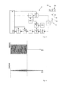
- FIG. 5 again shows the time profiles of the excitation signal and of the response signal, but for a transmission frequency close to the resonance frequency. In contrast to the course from FIG. 4, the amplitudes of the response signal are significantly larger here.
- the transmission frequency is increased by 5 kHz for each further measurement. For example, from the first transmission frequency 433 MHz to the second transmission frequency 433.005 MHz.
- the stored signal level is compared in the arithmetic unit MC with the current signal level. If the signal level is greater, for example, in the second measurement than in the first measurement, the signal level of the first measurement and the associated transmission frequency, namely 433 MHz, are deleted from the memory.
- the memory is then overwritten with the signal level of the second measurement with the associated transmission frequency, namely 433.005 MHz, which in turn is compared with the signal level of the third measurement, and so on. If the frequency band has been completed in this way, the largest signal level and the associated transmission frequency is determined.
- the current temperature on the surface acoustic wave component 24 can then be ascertained in a manner known to the person skilled in the art by means of the transmission frequency.
- FIG. 6 shows the signal level as a function of the transmission frequency.
- the signal level at the resonant frequency stands out clearly from the other signal levels, so that an evaluation and thus the determination of the current temperature at the surface acoustic wave device 24 is made possible in a simple manner.
- recalibration of the surface acoustic wave device 24 is automatically performed at regular and predetermined time intervals. This can be done, for example, each before heating the baking muffle 6 of ambient temperature.
- the further temperature measuring probe 12 is used. If the temperatures determined by the temperature measuring probes 18 and 12 deviate from one another, all the temperature and resonance frequency assignments stored for the surface acoustic wave component 24 are corrected by this difference.
- a single surface wave component 24 applies analogously to the other surface wave components 24 of the temperature measuring probe 18.
- the frequency band is further divided into narrower frequency bands corresponding to the number of surface acoustic wave components 24.
- a trained as a spit temperature probe 18 could be determined from the signal levels, an average cooking temperature. Also, the determination of the lowest and highest temperature present in the food 16 at the same time is conceivable.
- the temperatures determined in this way are used to control the cooking process.
- the type of heating and the heating intensity and the flushing of the baking muffle 6 is regulated with fresh air.
- the current temperatures are displayed on the display device 4.
- other regulations of the cooking process are thereby made possible.
- the temperature measuring probe 18 could be arranged fixed on or in the baking muffle 6, for example on the receptacles for the food support 14.
- Other forms known to those skilled in the art and suitable forms than those of a cooking spit and arrangements for the temperature measuring probe 18 are conceivable.
- the above-mentioned preparation of the response signal before its transmission to the evaluation circuit is not absolutely necessary, but merely facilitates the evaluation and reduces the circuitry complexity. In principle, however, it is also conceivable to evaluate the high-frequency, non-rectified response signal. Furthermore, the teaching according to the invention is not limited to the use of an integrator INT for evaluating the response signal. Other known and suitable circuits and methods for generating a signal level are also conceivable.
Landscapes
- Physics & Mathematics (AREA)
- General Physics & Mathematics (AREA)
- Engineering & Computer Science (AREA)
- Acoustics & Sound (AREA)
- Computer Networks & Wireless Communication (AREA)
- Chemical & Material Sciences (AREA)
- Combustion & Propulsion (AREA)
- Mechanical Engineering (AREA)
- General Engineering & Computer Science (AREA)
- Measuring Temperature Or Quantity Of Heat (AREA)
- Arrangements For Transmission Of Measured Signals (AREA)
Abstract
- Erzeugung einer hochfrequenten elektromagnetischen Erregerwelle einer vorher festgelegten Sendefrequenz aus einem Frequenzband, in dem die temperaturabhängigen Resonanzfrequenzen eines in einer Temperaturmesssonde (18) integrierten Oberflächenwellenbauelements (24) enthalten sind, die den bei dem Betrieb des Haushaltsgeräts an der Temperaturmesssonde (18) zu erwartendenden Temperaturen entsprechen, wobei die Erzeugung der Erregerwelle mittels einer elektrischen Verarbeitungseinheit (8) des Haushaltsgeräts erfolgt,
- drahtlose Übertragung der Erregerwelle auf das Oberflächenwellenbauelement (24) der Temperaturmesssonde (18) während einer ersten Phase,
- drahtlose Rückübertragung einer durch die Erregerwelle in dem Oberflächenwellenbauelement (24) erzeugten elektromagnetischen Antwortwelle an die Verarbeitungseinheit (8) während einer unmittelbar an die erste Phase anschließenden zweiten Phase,
- Messung des Signalpegels des aus der Antwortwelle erzeugten Antwortsignals in einer Auswerteschaltung der Verarbeitungseinheit (8) während der zweiten Phase und Abspeicherung des Signalpegels und der zugehörigen Sendefrequenz in einem Speicher der Verarbeitungseinheit (8),
- Wiederholung der vorgenannten Verfahrensschritte für eine Vielzahl von voneinander verschiedenen Frequenzen aus dem Frequenzband als jeweils eine Messung,
- Vergleich zumindest des Signalpegels aus der aktuellen Messung mit dem Signalpegel der letzten Messung und
- Ermittlung der aktuellen Temperatur des Oberflächenwellenbauelements (24) mittels der Auswahl der Sendefrequenz mit dem größten Signalpegel.
Description
- Die Erfindung betrifft ein Verfahren zur Temperaturmessung bei einem Haushaltsgerät.
- Ein derartiges Verfahren ist beispielsweise aus der
DE 29 35 282 C2 bekannt. Bei dem bekannten Verfahren wird eine hochfrequente elektromagnetische Erregerwelle mittels einer Verarbeitungseinheit des Haushaltsgeräts erzeugt. Die vorher festgelegte Sendefrequenz ist aus einem Frequenzband, in dem die temperaturabhängigen Resonanzfrequenzen eines in einer Temperaturmesssonde integrierten LC-Resonanzkreises enthalten sind, die den bei dem Betrieb des Haushaltsgeräts an der Temperaturmesssonde zu erwartendenden Temperaturen entsprechen. Während einer ersten Phase wird die Erregerwelle drahtlos auf den LC-Resonanzkreis der Temperaturmesssonde übertragen. Als Folge davon wird in dem LC-Resonanzkreis eine elektromagnetische Antwortwelle erzeugt, die während einer an die erste Phase unmittelbar anschließenden zweiten Phase drahtlos an die Verarbeitungseinheit rückübertragen wird. Der vorgenannte Verfahrensablauf wiederholt sich fortlaufend, wobei die Sendefrequenz in festgelegten Frequenzschritten erhöht wird, bis das Frequenzband durchlaufen ist. Die von der Verarbeitungseinheit empfangenen Antwortwellen werden in Antwortsignale umgewandelt und in einer Auswerteschaltung der Verarbeitungseinheit wird mittels eines Impulszählers die temperaturabhängige Resonanzfrequenz und damit die Temperatur an der Temperaturmesssonde ermittelt. Ein Nachteil der bekannten Anordnung ist, dass LC-Resonanzkreise in der Regel nicht für den Einsatz bei hohen Temperaturen, beispielsweise im Bereich um etwa 250°C, geeignet sind. - Der Erfindung stellt sich somit das Problem ein Verfahren zur Temperaturmessung bei einem Haushaltsgerät anzugeben, das schaltungstechnisch weniger aufwendig und weniger störungsanfällig ist und auch für den Einsatz bei höheren Temperaturen geeignet ist.
- Erfindungsgemäß wird dieses Problem durch ein Verfahren mit den Merkmalen des Patentanspruchs 1 gelöst. Vorteilhafte Ausgestaltungen und Weiterbildungen der Erfindung ergeben sich aus den nachfolgenden Unteransprüchen.
- Die mit der Erfindung erreichbaren Vorteile bestehen neben einer weniger aufwendigen Schaltungstechnik und einer geringeren Störungsanfälligkeit insbesondere in den geringeren Herstellkosten.
- Zwar ist es beispielsweise aus der
DE 197 23 127 A1 bekannt, Oberflächenwellenbauelemente zu Temperaturmesszwecken bei Kochfeldern einzusetzen. Das Auswerteverfahren sieht hier jedoch vor, mittels der Phasenverschiebung zwischen den Impulsmustern der Antwortsignale auf die Temperatur an der Temperaturmesssonde zu schließen. Gleiches gilt für den Gegenstand derDE 198 28 170 A1 . Alternativ hierzu wird in derDE 44 13 211 A1 vorgeschlagen, die Antwortsignale mittels Fourier-Transformation auszuwerten. - Eine zweckmäßige Weiterbildung der erfindungsgemäßen Lehre sieht vor, dass die aktuelle Temperatur zur Regelung des Garprozesses verwendet und/oder auf einer Anzeigeeinrichtung des Haushaltsgeräts angezeigt wird.
- Eine vorteilhafte Weiterbildung sieht vor, dass die Sendefrequenz aus dem Frequenzband von etwa 433 MHz bis etwa 434 MHz gewählt wird und sich die in dem Frequenzband direkt benachbarten Sendefrequenzen um etwa 5 kHz oder weniger voneinander unterscheiden. Dieses Frequenzband ist in mehreren Staaten ohne Einschränkungen nutzbar. Ein weiteres vorteilhaftes Frequenzband wäre von etwa 868 MHz bis etwa 869 MHz, da hier die Antenne für das Senden der Erregerwelle und das Empfangen der Antwortwelle kleiner und damit platzsparender ausgebildet sein kann.
- Eine weitere vorteilhafte Weiterbildung sieht vor, dass das hochfrequente Antwortsignal vor der Verarbeitung in der Auswerteschaltung in der Verarbeitungseinheit in ein niederfrequentes Antwortsignal umgewandelt wird. Hierdurch ist die weitere Verarbeitung vereinfacht. Einfachere und damit kostengünstigere elektrische Schaltungen sind dadurch ermöglicht.
- Eine andere vorteilhafte Weiterbildung sieht vor, dass das Antwortsignal vor der Verarbeitung in der Auswerteschaltung in der Verarbeitungseinheit gleichgerichtet wird. Hierdurch ist die weitere Verarbeitung weiter vereinfacht.
- Eine besonders vorteilhafte Weiterbildung sieht vor, dass die gleiche Sendefrequenz mehrfach unmittelbar nacheinander verwendet wird und aus den einzelnen Signalpegeln zu einer Sendefrequenz ein mittlerer Signalpegel gebildet, abgespeichert und für den Vergleich verwendet wird. Auf diese Weise ist die Genauigkeit der Temperaturmessung verbessert.
- Eine vorteilhafte Weiterbildung sieht vor, dass die von mindestens zwei Oberflächenwellenbauelementen im gleichen Frequenzband erzeugten Signalpegel in der Auswerteschaltung ausgewertet werden. Hierdurch ist der schaltungstechnische Aufwand bei der Verwendung von mindestens zwei Oberflächenbauelementen reduziert.
- Eine andere vorteilhafte Ausführungsform sieht vor, dass der Speicher jeweils nur den bis zur aktuellen Messung größten Signalpegel sowie die zugeordnete Sendefrequenz enthält. Auf diese Weise ist der erforderliche Speicherplatz verringert.
- Eine besonders vorteilhafte Weiterbildung der erfindungsgemäßen Lehre sieht vor, dass zeitlich vor den übrigen Verfahrensschritten in einem ersten Verfahrensschritt mittels einer weiteren mit der Verarbeitungseinheit in Signalübertragungsverbindung stehenden Temperaturmesssonde mit einem Temperatursensor, der eine im Wesentlichen über dessen Lebensdauer konstante Korrelation zwischen Eingangs- und Ausgangsgröße aufweist, in der Auswerteschaltung eine Nachkalibrierung der dem Oberflächenwellenbauelement oder den einzelnen Oberflächenwellenbauelementen zugeordneten temperaturabhängigen Resonanzfrequenzen erfolgt. Hierdurch ist die Genauigkeit der Temperaturmessung weiter verbessert.
- Eine weitere vorteilhafte Weiterbildung sieht vor, dass für die Temperaturmessung mit mindestens zwei Oberflächenwellenbauelementen zumindest zwei voneinander verschiedene Frequenzbänder verwendet werden, wobei den mindestens zwei Oberflächenbauelementen jeweils ein Frequenzband zugeordnet ist. Auf diese Weise ist eine eindeutige Zuordnung eines Antwortsignals zu einem Oberflächenwellenbauelement ermöglicht.
- Ein Ausführungsbeispiel der Erfindung ist in den Zeichnungen rein schematisch dargestellt und wird nachfolgend näher beschrieben. Es zeigt
- Figur 1
- ein Haushaltsgerät, bei dem ein erfindungsgemäßes Verfahren eingesetzt wird, in einer Frontansicht,
- Figur 2
- die Temperaturmesssonde aus Fig. 1 in einer geschnittenen Seitenansicht,
- Figur 3
- ein Blockschaltbild der Verarbeitungseinheit und der Temperaturmesssonde,
- Figur 4
- eine Amplituden-Zeit-Darstellung des Erreger- und des Antwortsignals bei einer Sendefrequenz fern der Resonanzfrequenz des Oberflächenwellenbauelements,
- Figur 5
- eine Amplituden-Zeit-Darstellung des Erreger- und des Antwortsignals bei einer Sendefrequenz nahe der Resonanzfrequenz des Oberflächenwellenbauelements und
- Figur 6
- den Signalpegel in Abhängigkeit der Sendefrequenz.
- In Fig. 1 ist ein als Backofen ausgebildetes Haushaltsgerät dargestellt, bei dem das erfindungsgemäße Verfahren verwendet wird. Der Backofen weist Bedienelemente 2 und eine Anzeigeeinrichtung 4, eine Backmuffel 6 und eine durch eine gestrichelte Linie symbolisierte elektrische Verarbeitungseinheit 8 auf. Die Bedienelemente 2 und die Anzeigeeinrichtung 4 sind auf dem Fachmann bekannte Weise mit der elektrischen Verarbeitungseinheit 8 signalübertragend verbunden. Gleiches gilt für eine in der Backmuffel 6 angeordnete Garraumantenne 10 und eine ebenfalls in der Backmuffel 6 angeordnete weitere Temperaturmesssonde 12. Die weitere Temperaturmesssonde 12 weist hier einen als PT 1000 ausgebildeten Temperatursensor auf. Grundsätzlich sind jedoch auch andere Ausführungsformen des Temperatursensors denkbar, die eine im Wesentlichen über deren Lebensdauer konstante Korrelation zwischen Eingangs- und Ausgangsgröße aufweisen. Ferner ist es denkbar, dass nicht nur eine weitere Temperaturmesssonde 12 sondern eine Mehrzahl von weiteren Temperaturmesssonden 12 verwendet werden, was nachfolgend noch näher erläutert wird.
- In die Backmuffel 6 ist ein auf einem Gargutträger 14 aufgelegtes als Fleischstück ausgebildetes Gargut 16 eingeschoben, in das eine als Garspieß ausgebildete Temperaturmesssonde 18 eingestochen ist. Der Aufbau der Temperaturmesssonde 18 ist anhand von Fig. 2 näher erläutert. Grundsätzlich sind die Temperaturmesssonden 12 und 18 nach Art, Material, Dimension und Anordnung in weiten geeigneten Grenzen wählbar.
- Fig. 2 zeigt die Temperaturmesssonde 18 im Detail. Die Temperaturmesssonde 18 weist einen Spieß 20 und ein Griffstück 22 auf, wobei in dem Spieß 20 mehrere als Oberflächenwellenbauelemente 24 ausgebildete Temperatursensoren angeordnet sind. Die Oberflächenwellenbauelemente 24 sind derart ausgewählt, dass die temperaturabhängigen Resonanzfrequenzen, die den bei dem Betrieb des Haushaltsgeräts an der Temperaturmesssonde 18 zu erwartenden Temperaturen entsprechen, in dem für das vorliegende Ausführungsbeispiel ausgewählten Frequenzband von etwa 433 MHz bis etwa 434 MHz enthalten sind. Die einzelnen Oberflächenwellenbauelemente 24 sind auf dem Fachmann bekannte Weise mit einer im Griffstück 22 angeordneten Antenne 26 elektrisch leitend verbunden. Um die Antenne 26 möglichst platzsparend auszubilden, ist diese teilweise als Verlängerungsspule ausgebildet. Diese Ausbildung der Antenne 26 ist jedoch nicht zwingend erforderlich.
- Das Zusammenwirken von Temperaturmesssonde 18 und Verarbeitungseinheit 8 ist anhand von Fig. 3 beispielhaft erläutert. Zur einfacheren Darstellung wird die Funktionsweise lediglich anhand eines einzigen Oberflächenwellenbauelements 24 erläutert.
- In Fig. 3 ist ein Blockschaltbild dargestellt, das in der Bildebene links die Verarbeitungseinheit 8 und in der Bildebene rechts die Temperaturmesssonde 18 beinhaltet. Die Verarbeitungseinheit 8 weist eine Recheneinheit MC, die mit einem Phasenregelkreis PLL, einem Oszillator OSZ 1 und einen Leistungsverstärker PA derart verbunden ist, dass ein hochfrequentes Erregersignal erzeugbar ist und während einer ersten Phase als hochfrequente Erregerwelle über ein Netzwerk zur Antennenanpassung AA und die Garraumantenne 10 in Richtung der in der Backmuffel 6 befindlichen Temperaturmesssonde 18 abstrahlbar ist. Die Sendefrequenz des Erregersignals und damit der elektromagnetischen Erregerwelle ist hier aus dem Frequenzband von etwa 433 MHz bis etwa 434 MHz ausgewählt. Zu Anfang beträgt die Sendefrequenz hier 433 MHz. Die Erregerwelle wird, wie in Fig. 1 und 3 durch gekrümmte Linien 28 symbolisiert, drahtlos an die Antenne 26 übertragen. Während der ersten Phase ist die aus einem rücksetzbaren Integrator INT und einem Analog-Digitalwandler A/D bestehende Auswerteschaltung durch einen Schalter SW verriegelt, so dass die während der ersten Phase durch die Garraumantenne 10 empfangenen elektromagnetischen Wellen und die daraus erzeugten elektrischen Signale nicht ausgewertet werden. Siehe hierzu Fig. 3. Grundsätzlich sind jedoch auch andere dem Fachmann bekannte und geeignete Verriegelungen möglich.
- In den mit der Antenne 26 elektrisch leitend verbundenen Oberflächenwellenbauelementen 24, von denen in Fig. 3 lediglich eines symbolisch dargestellt ist, werden auf dem Fachmann bekannte Weise elektromagnetische Antwortwellen erzeugt, die in einer unmittelbar an die erste Phase anschließenden zweiten Phase mittels der Antenne 26 und der Garraumantenne 10 an die Verarbeitungseinheit 8 drahtlos rückübertragen wird. Während der zweiten Phase wird kein Erregersignal erzeugt und damit auch keine Erregerwelle ausgestrahlt. Dies ist in den Fig. 1 und 3 durch gekrümmte Linien 30 symbolisiert. Die rückübertragene elektromagnetische Antwortwelle erzeugt in der Verarbeitungseinheit 8 ein Antwortsignal, das nachfolgend auf dem Fachmann bekannte Weise und wie in Fig. 3 durch die Symbole LNA für einen Eingangsverstärker, MIX 1 und MIX 2 für Mischer, OSZ 2 für einen Oszillator und FLT für einen Filter schematisch dargestellt verstärkt, in ein niederfrequentes Signal umgewandelt und gefiltert wird. Während dieser zweiten Phase ist der Schalter SW mittels der Recheneinheit MC geschlossen, so dass das Antwortsignal in die Auswerteeinheit gelangen kann. Mittels des Integrators INT wird das vorher gleichgerichtete Antwortsignal integriert und der Signalpegel des Antwortsignals ermittelt, also die Beträge der Amplitudenwerte des Antwortsignals werden aufsummiert. Anschließend wird der Signalpegel in dem Analog-Digitalwandler A/D der Recheneinheit MC digitalisiert und in einem Speicher der Recheneinheit MC zusammen mit der zugehörigen Sendefrequenz abgespeichert.
- Die Zeitdauer der ersten Phase muss derart bemessen sein, dass das Oberflächenwellenbauelement 24 im Resonanzfall ausreichend angeregt werden kann, beispielsweise 100 µs. Da die Antwortwelle und damit das Antwortsignal erfahrungsgemäß in einem Zeitraum von 30 bis 50 µs abgeklungen ist, reicht es aus, wenn die zweite Phase auf 50 µs festgelegt ist. Davon abweichende Zeitdauern für die erste und die zweite Phase sind jedoch auch denkbar.
- Das Erregersignal und das Antwortsignal werden anhand der Fig. 4 und 5 nachfolgend erläutert.
- In Fig. 4 sind das Erregersignal und das Antwortsignal für den Fall dargestellt, dass die für die aktuelle Messung verwendete Sendefrequenz fern der Resonanzfrequenz liegt. In dem oberen Teil von Fig. 4 ist der zeitliche Verlauf des Erregersignals dargestellt, während in dem unteren Teil der zeitliche Verlauf des Antwortsignals dargestellt ist. Der Wechsel von der in der Bildebene links dargestellten ersten Phase auf die in der Bildebene rechts dargestellten zweiten Phase ist durch eine gestrichelte Linie visualisiert. Wie durch die Zunahme der Amplitude des Antwortsignals in Fig. 4 deutlich ersichtlich, wird das Oberflächenwellenbauelement 24 während der ersten Phase zu Schwingungen angeregt. Da die Sendefrequenz fern der Resonanzfrequenz liegt, sind die Amplituden des Antwortsignals jedoch niedrig. Nach Beendigung der ersten Phase und damit der Anregung des Oberflächenwellenbauelements 24 nimmt die Amplitude des Antwortsignals wieder bis auf Null ab.
- Fig. 5 zeigt wiederum die zeitlichen Verläufe des Erregersignals und des Antwortsignals, jedoch für eine Sendefrequenz nahe der Resonanzfrequenz. Im Unterschied zu dem Verlauf aus Fig. 4 sind hier die Amplituden des Antwortsignals deutlich größer.
- Der vorgenannte Ablauf wird für eine Vielzahl von voneinander verschiedenen Sendefrequenzen wiederholt, wobei der Integrator INT jeweils vor der Durchführung der nächsten Messung zurückgesetzt werden muss. Bei dem vorliegenden Ausführungsbeispiel wird die Sendefrequenz für jede weitere Messung um 5 kHz erhöht. Also beispielsweise von der ersten Sendefrequenz 433 MHz auf die zweite Sendefrequenz 433,005 MHz. Um den Speicherplatzbedarf möglichst gering zu halten, wird hierbei lediglich der bis zur aktuellen Messung größte Signalpegel sowie die zugeordnete Sendefrequenz abgespeichert. Der abgespeicherte Signalpegel wird in der Recheneinheit MC mit dem aktuellen Signalpegel verglichen. Ist der Signalpegel beispielsweise bei der zweiten Messung größer als bei der ersten Messung, so wird der Signalpegel der ersten Messung und die dazugehörige Sendefrequenz, nämlich 433 MHz, aus dem Speicher gelöscht. Der Speicher wird dann mit dem Signalpegel der zweiten Messung mit der dazugehörigen Sendefrequenz, nämlich 433,005 MHz, überschrieben, der wiederum mit dem Signalpegel der dritten Messung verglichen wird und so weiter. Ist das Frequenzband auf diese Weise vollständig durchlaufen worden, ist der größte Signalpegel und die dazugehörige Sendefrequenz ermittelt. Über eine in der Recheneinheit MC hinterlegte Tabelle oder Funktion kann dann auf dem Fachmann bekannte Weise mittels der Sendefrequenz die aktuelle Temperatur an dem Oberflächenwellenbauelement 24 ermittelt werden.
- In Fig. 6 ist der Signalpegel in Abhängigkeit der Sendefrequenz dargestellt. Der Signalpegel bei der Resonanzfrequenz hebt sich deutlich von den anderen Signalpegeln ab, so dass eine Auswertung und damit die Ermittlung der aktuellen Temperatur an dem Oberflächenwellenbauelement 24 auf einfache Weise ermöglicht ist.
- Um beispielsweise die negativen Auswirkungen einer Drift über die Lebensdauer des Oberflächenwellenbauelements 24 auf die Genauigkeit der Temperaturmessung zu reduzieren oder zu verhindern, wird bei dem vorliegenden Ausführungsbeispiel in regelmäßigen und vorher festgelegten Zeitabständen automatisch eine Nachkalibrierung des Oberflächenwellenbauelements 24 durchgeführt. Diese kann beispielsweise jeweils vor dem Aufheizen der Backmuffel 6 von Umgebungstemperatur erfolgen. Hierzu wird die weitere Temperaturmesssonde 12 verwendet. Sofern die durch die Temperaturmesssonden 18 und 12 ermittelten Temperaturen voneinander abweichen, werden alle für das Oberflächenwellenbauelement 24 abgespeicherten Zuordnungen von Temperatur und Resonanzfrequenz jeweils um diesen Differenzbetrag korrigiert. Um die Genauigkeit der Nachkalibrierung zu verbessern wäre es auch denkbar, die Nachkalibrierung in Abhängigkeit von mehreren Temperaturmessungen, insbesondere bei voneinander verschiedenen Temperaturen, durchzuführen.
- Die obigen Ausführungen bezüglich eines einzigen Oberflächenwellenbauelements 24 gelten analog für die übrigen Oberflächenwellenbauelemente 24 der Temperaturmesssonde 18. Um die Antwortsignale dem jeweiligen Oberflächenwellenbauelement 24 eindeutig zuordnen zu können, ist hier das Frequenzband entsprechend der Anzahl der Oberflächenwellenbauelemente 24 weiter in schmalere Frequenzbänder unterteilt. Alternativ hierzu wäre es auch denkbar, allen Oberflächenwellenbauelementen 24 ein einziges gemeinsames Frequenzband zuzuordnen. In diesem Fall ist aber ein größerer Speicherplatz erforderlich, da mehrere Signalpegel gleichzeitig verarbeitet werden müssen. Im vorliegenden Fall einer als Garspieß ausgebildeten Temperaturmesssonde 18 könnte aus den Signalpegeln eine mittlere Garguttemperatur ermittelt werden. Auch wäre die Ermittlung der gleichzeitig vorliegenden niedrigsten und höchsten Temperatur im Gargut 16 denkbar.
- Bei dem vorliegenden Ausführungsbeispiel werden die auf diese Weise ermittelten Temperaturen zur Regelung des Garprozesses verwendet. Je nachdem wie die Temperaturverteilung in dem Gargut 16 ist, wird die Beheizungsart und die Beheizungsintensität sowie die Durchspülung der Backmuffel 6 mit Frischluft geregelt. Darüber hinaus werden die aktuellen Temperaturen auf der Anzeigeeinrichtung 4 angezeigt. Jedoch sind auch andere Regelungen des Garprozesses hierdurch ermöglicht.
- Abweichend von dem Ausführungsbeispiel sind auch andere Anordnungen und Ausbildungen der Temperaturmesssonde 18 denkbar. Die Temperaturmesssonde 18 könnte lagefest an oder in der Backmuffel 6, beispielsweise an den Aufnahmen für die Gargutträger 14, angeordnet sein. Ferner sind auch andere dem Fachmann bekannte und geeignete Formen als die eines Garspießes und Anordnungen für die Temperaturmesssonde 18 denkbar.
- Um die Genauigkeit der Temperaturmessung zu erhöhen, wäre es möglich, den Abstand zwischen den einzelnen Sendefrequenzen geringer als 5 kHz zu wählen.
- Die oben genannte Aufbereitung des Antwortsignals vor dessen Weiterleitung an die Auswerteschaltung ist nicht zwingend erforderlich, sondern erleichtert lediglich die Auswertung und reduziert den schaltungstechnischen Aufwand. Grundsätzlich ist es jedoch auch denkbar, das hochfrequente, nicht gleichgerichtete Antwortsignal auszuwerten. Ferner ist die erfindungsgemäße Lehre nicht auf die Verwendung eines Integrators INT zur Auswertung des Antwortsignals beschränkt. Andere dem Fachmann bekannte und geeignete Schaltungen und Verfahren zur Erzeugung eines Signalpegels sind auch denkbar.
Claims (10)
- Verfahren zur Temperaturmessung bei einem Haushaltsgerät, das folgende Verfahrensschritte aufweist:- Erzeugung einer hochfrequenten elektromagnetischen Erregerwelle einer vorher festgelegten Sendefrequenz aus einem Frequenzband, in dem die temperaturabhängigen Resonanzfrequenzen eines in einer Temperaturmesssonde integrierten Oberflächenwellenbauelements enthalten sind, die den bei dem Betrieb des Haushaltsgeräts an der Temperaturmesssonde zu erwartendenden Temperaturen entsprechen, wobei die Erzeugung der Erregerwelle mittels einer elektrischen Verarbeitungseinheit des Haushaltsgeräts erfolgt,- drahtlose Übertragung der Erregerwelle auf das Oberflächenwellenbauelement der Temperaturmesssonde während einer ersten Phase,- drahtlose Rückübertragung einer durch die Erregerwelle in dem Oberflächenwellenbauelement erzeugten elektromagnetischen Antwortwelle an die Verarbeitungseinheit während einer unmittelbar an die erste Phase anschließenden zweiten Phase,- Messung des Signalpegels des aus der Antwortwelle erzeugten Antwortsignals in einer Auswerteschaltung der Verarbeitungseinheit während der zweiten Phase und Abspeicherung des Signalpegels und der zugehörigen Sendefrequenz in einem Speicher der Verarbeitungseinheit,- Wiederholung der vorgenannten Verfahrensschritte für eine Vielzahl von voneinander verschiedenen Frequenzen aus dem Frequenzband als jeweils eine Messung,- Vergleich zumindest des Signalpegels aus der aktuellen Messung mit dem Signalpegel der letzten Messung und- Ermittlung der aktuellen Temperatur des Oberflächenwellenbauelements mittels der Auswahl der Sendefrequenz mit dem größten Signalpegel.
- Verfahren nach Anspruch 1,
dadurch gekennzeichnet,
dass die aktuelle Temperatur zur Regelung des Garprozesses verwendet und/oder auf einer Anzeigeeinrichtung (4) des Haushaltsgeräts angezeigt wird. - Verfahren nach einem der Ansprüche 1 oder 2,
dadurch gekennzeichnet,
dass die Sendefrequenz aus dem Frequenzband von etwa 433 MHz bis etwa 434 MHz gewählt wird und sich die in dem Frequenzband direkt benachbarten Sendefrequenzen um etwa 5 kHz oder weniger voneinander unterscheiden. - Verfahren nach einem der Ansprüche 1 bis 3,
dadurch gekennzeichnet,
dass das hochfrequente Antwortsignal vor der Verarbeitung in der Auswerteschaltung in der Verarbeitungseinheit (8) in ein niederfrequentes Antwortsignal umgewandelt wird. - Verfahren nach mindestens einem der Ansprüche 1 bis 4,
dadurch gekennzeichnet,
dass das Antwortsignal vor der Verarbeitung in der Auswerteschaltung in der Verarbeitungseinheit (8) gleichgerichtet wird. - Verfahren nach mindestens einem der Ansprüche 1 bis 5,
dadurch gekennzeichnet,
dass die gleiche Sendefrequenz mehrfach unmittelbar nacheinander verwendet wird und aus den einzelnen Signalpegeln zu einer Sendefrequenz ein mittlerer Signalpegel gebildet, abgespeichert und für den Vergleich verwendet wird. - Verfahren nach mindestens einem der Ansprüche 1 bis 6,
dadurch gekennzeichnet,
dass die von mindestens zwei Oberflächenwellenbauelementen (24) im gleichen Frequenzband erzeugten Signalpegel in der Auswerteschaltung ausgewertet werden. - Verfahren nach mindestens einem der Ansprüche 1 bis 6,
dadurch gekennzeichnet,
dass jeweils nur der bis zur aktuellen Messung größte Signalpegel sowie die zugeordnete Sendefrequenz abgespeichert wird. - Verfahren nach mindestens einem der Ansprüche 1 bis 8,
dadurch gekennzeichnet,
dass zeitlich vor den übrigen Verfahrensschritten in einem ersten Verfahrensschritt mittels einer weiteren mit der Verarbeitungseinheit (8) in Signalübertragungsverbindung stehenden Temperaturmesssonde (12) mit einem Temperatursensor, der eine im Wesentlichen über dessen Lebensdauer konstante Korrelation zwischen Eingangs- und Ausgangsgröße aufweist, in der Auswerteschaltung eine Nachkalibrierung der dem Oberflächenwellenbauelement (24) oder den einzelnen Oberflächenwellenbauelementen (24) zugeordneten temperaturabhängigen Resonanzfrequenzen erfolgt. - Verfahren nach mindestens einem der Ansprüche 1 bis 6 sowie 8 und 9,
dadurch gekennzeichnet,
dass für die Temperaturmessung mit mindestens zwei Oberflächenwellenbauelementen (24) zumindest zwei voneinander verschiedene Frequenzbänder verwendet werden, wobei den mindestens zwei Oberflächenbauelementen (24) jeweils ein Frequenzband zugeordnet ist.
Priority Applications (2)
| Application Number | Priority Date | Filing Date | Title |
|---|---|---|---|
| PL06004577T PL1708540T3 (pl) | 2005-03-31 | 2006-03-07 | Sposób mierzenia temperatury w sprzęcie gospodarstwa domowego |
| SI200631394T SI1708540T1 (sl) | 2005-03-31 | 2006-03-07 | Postopek merjenja temperature v gospodinjskem aparatu |
Applications Claiming Priority (1)
| Application Number | Priority Date | Filing Date | Title |
|---|---|---|---|
| DE102005015028A DE102005015028B4 (de) | 2005-03-31 | 2005-03-31 | Verfahren zur Temperaturmessung bei einem Haushaltsgerät |
Publications (3)
| Publication Number | Publication Date |
|---|---|
| EP1708540A2 true EP1708540A2 (de) | 2006-10-04 |
| EP1708540A3 EP1708540A3 (de) | 2011-03-09 |
| EP1708540B1 EP1708540B1 (de) | 2012-07-04 |
Family
ID=36694147
Family Applications (1)
| Application Number | Title | Priority Date | Filing Date |
|---|---|---|---|
| EP06004577A Expired - Lifetime EP1708540B1 (de) | 2005-03-31 | 2006-03-07 | Verfahren zur Temperaturmessung bei einem Haushaltsgerät |
Country Status (6)
| Country | Link |
|---|---|
| US (1) | US7358464B2 (de) |
| EP (1) | EP1708540B1 (de) |
| DE (1) | DE102005015028B4 (de) |
| ES (1) | ES2387813T3 (de) |
| PL (1) | PL1708540T3 (de) |
| SI (1) | SI1708540T1 (de) |
Cited By (3)
| Publication number | Priority date | Publication date | Assignee | Title |
|---|---|---|---|---|
| CN102289924A (zh) * | 2011-05-23 | 2011-12-21 | 国网电力科学研究院 | 一种架空输电线路测温装置 |
| WO2012013540A1 (de) * | 2010-07-28 | 2012-02-02 | Siemens Ag Österreich | Verfahren zur ansteuerung passiver sensorelemente |
| EP3182084A1 (de) * | 2015-12-17 | 2017-06-21 | pro.micron GmbH & Co.KG | Verfahren zur abfrage von messwerten einer sich zeitlich verändernden messgrösse von einem saw-sensor |
Families Citing this family (48)
| Publication number | Priority date | Publication date | Assignee | Title |
|---|---|---|---|---|
| US20080043809A1 (en) * | 2006-08-18 | 2008-02-21 | Herbert Curtis B | Thermometer |
| DE102006055420B4 (de) * | 2006-11-22 | 2008-07-31 | Miele & Cie. Kg | Verfahren zur Erkennung eines Fehlers in einem Messdurchlauf |
| DE102007019403B4 (de) | 2007-04-23 | 2009-05-14 | Miele & Cie. Kg | Temperaturmesssonde, insbesondere für ein Haushaltsgerät |
| US20090188396A1 (en) * | 2007-08-06 | 2009-07-30 | Hofmann Matthias C | Oven with wireless temperature sensor for use in monitoring food temperature |
| EP3121573B1 (de) | 2008-05-08 | 2020-03-25 | Electrolux Home Products Corporation N.V. | Ofen, insbesondere backofen oder mikrowellenofen |
| EP2233899B1 (de) | 2009-03-28 | 2015-09-30 | Electrolux Home Products Corporation N.V. | Temperatursonde, Temperatursondiersystem und Vorrichtung zum Erwärmen oder Kühlen einer Substanz mit einem derartigen Temperatursondiersystem |
| DE102009056060B4 (de) | 2009-08-19 | 2011-09-22 | Vectron International Gmbh & Co.Kg | Messsystem zur drahtlosen positionsunabhängigen Messung der Temperatur |
| DE102010033632B4 (de) | 2010-08-06 | 2023-06-01 | Rational Aktiengesellschaft | Verfahren zum drahtlosen Auslesen von Temperatursensoren in einem Garofen zur Überwachung eines Garvorgangs und System zum Steuern eines Garofens |
| WO2012100125A2 (en) * | 2011-01-20 | 2012-07-26 | Delaware Capital Formation, Inc. | Spiralpole small antenna system |
| US8556502B2 (en) * | 2011-11-22 | 2013-10-15 | Electronic Controls Design, Inc. | Food temperature probe |
| DE102012200294A1 (de) * | 2012-01-11 | 2013-07-11 | BSH Bosch und Siemens Hausgeräte GmbH | Verfahren und Vorrichtung zur Erkennung einer Zugehörigkeit eines Temperatursensors zu einer Kochzone |
| EP2662004B1 (de) * | 2012-05-07 | 2014-08-27 | Electrolux Home Products Corporation N.V. | Temperaturdetektionseinrichtung zur Temperaturbestimmung des Bodens eines auf einem Kochfeld aufgestellten Kochgefäss |
| DE102012208434A1 (de) | 2012-05-21 | 2013-11-21 | BSH Bosch und Siemens Hausgeräte GmbH | Gargutthermometer mit Gleichstrom-Energieerzeugungseinheit |
| DE102012221015A1 (de) * | 2012-11-16 | 2014-05-22 | E.G.O. Elektro-Gerätebau GmbH | Gargerät |
| DE102012112855B4 (de) | 2012-12-21 | 2022-11-17 | Rational Ag | Gargerätmesseinheit mit mehreren Sensoren und Verfahren zur Ermittlung einer physikalischen Messgröße |
| US10713726B1 (en) | 2013-01-13 | 2020-07-14 | United Services Automobile Association (Usaa) | Determining insurance policy modifications using informatic sensor data |
| US9883551B2 (en) * | 2013-03-15 | 2018-01-30 | Silgan Containers Llc | Induction heating system for food containers and method |
| US10237924B2 (en) * | 2013-03-15 | 2019-03-19 | Silgan Containers Llc | Temperature detection system for food container induction heating system and method |
| FR3005167B1 (fr) | 2013-04-30 | 2016-09-30 | Senseor | Systeme d'interrogation d'un capteur passif interrogeable a distance integre dans une cavite metallique a bilan energetique optimise et procede d'interrogation |
| GB2514116B (en) * | 2013-05-13 | 2016-02-10 | Intellistat Ltd | Temperature control |
| WO2014194176A1 (en) * | 2013-05-30 | 2014-12-04 | Knowles Capital Formation Inc. | Wireless culinary probe calibration method and system |
| US9710858B1 (en) | 2013-08-16 | 2017-07-18 | United Services Automobile Association (Usaa) | Insurance policy alterations using informatic sensor data |
| US11416941B1 (en) | 2014-01-10 | 2022-08-16 | United Services Automobile Association (Usaa) | Electronic sensor management |
| US10552911B1 (en) | 2014-01-10 | 2020-02-04 | United Services Automobile Association (Usaa) | Determining status of building modifications using informatics sensor data |
| US11087404B1 (en) | 2014-01-10 | 2021-08-10 | United Services Automobile Association (Usaa) | Electronic sensor management |
| US12100050B1 (en) | 2014-01-10 | 2024-09-24 | United Services Automobile Association (Usaa) | Electronic sensor management |
| US20150208845A1 (en) * | 2014-01-27 | 2015-07-30 | CircuitLab, Inc. | Apparatus for cooking and methods |
| US11847666B1 (en) | 2014-02-24 | 2023-12-19 | United Services Automobile Association (Usaa) | Determining status of building modifications using informatics sensor data |
| US10614525B1 (en) | 2014-03-05 | 2020-04-07 | United Services Automobile Association (Usaa) | Utilizing credit and informatic data for insurance underwriting purposes |
| WO2015164174A1 (en) | 2014-04-24 | 2015-10-29 | Silgan Containers Llc | Food container induction heating system having power based microbial lethality monitoring |
| EP3140629A1 (de) * | 2014-05-05 | 2017-03-15 | Decorfood Italy S.r.l. | Thermometer für speisen |
| US10085584B2 (en) * | 2014-06-09 | 2018-10-02 | Whirlpool Corporation | Method of regulating temperature for sous vide cooking and apparatus therefor |
| PT3056882T (pt) | 2015-02-13 | 2020-03-04 | Vorwerk Co Interholding | Método para medição de uma temperatura dentro de um robô de cozinha |
| DE102015107944A1 (de) | 2015-05-20 | 2016-11-24 | Miele & Cie. Kg | Steuereinrichtung für die Steuerung von elektrischen Hausgeräten |
| DE102015109043B8 (de) * | 2015-06-09 | 2026-05-28 | Rational Aktiengesellschaft | Kerntemperaturfühler für ein Gargerät |
| DE102015215772A1 (de) * | 2015-08-19 | 2017-02-23 | BSH Hausgeräte GmbH | Kerntemperaturfühler, Mikrowellen-Gargerät und System |
| DE102015012683B3 (de) * | 2015-09-23 | 2016-11-03 | H. Heinz Messwiderstände GmbH | Temperaturmesssonde |
| DE102016102695A1 (de) * | 2016-02-16 | 2017-08-17 | Miele & Cie. Kg | Verfahren zum Backen und Gargerät |
| US10527290B2 (en) * | 2017-01-27 | 2020-01-07 | Haier Us Appliance Solutions, Inc. | Oven appliance and methods of operation |
| ES1200311Y (es) * | 2017-09-11 | 2018-02-23 | Copreci S Coop | Sistema de control de temperatura de un aparato de cocción, y aparato de cocción que comprende dicho sistema de control de temperatura |
| US11435238B2 (en) * | 2017-11-24 | 2022-09-06 | Mitsubishi Electric Cornoration | Temperature detection device and temperature detection method |
| US10641498B2 (en) * | 2018-01-08 | 2020-05-05 | Haier Us Appliance Solutions, Inc. | Antenna device for a wireless probe system of an oven appliance |
| US10856371B2 (en) * | 2018-06-26 | 2020-12-01 | Midea Group Co., Ltd. | Wireless sensor in a microwave oven |
| EP3798594A1 (de) * | 2019-09-26 | 2021-03-31 | Koninklijke Philips N.V. | Vorrichtung zum messen der temperatur eines objekts |
| US11882956B2 (en) | 2021-05-28 | 2024-01-30 | Whirlpool Corporation | Cooking adjustment system |
| ES2976314T3 (es) * | 2021-07-13 | 2024-07-29 | Vorwerk Co Interholding | Termómetro para alimentos y procedimiento para una preparación de alimentos |
| IT202200011852A1 (it) * | 2022-06-06 | 2023-12-06 | Elica Spa | Elettrodomestico per la cottura di pietanze |
| USD1101580S1 (en) | 2024-01-31 | 2025-11-11 | Sharkninja Operating Llc | Temperature probe holder |
Family Cites Families (9)
| Publication number | Priority date | Publication date | Assignee | Title |
|---|---|---|---|---|
| US4297557A (en) * | 1976-05-03 | 1981-10-27 | Robertshaw Controls Company | Microwave oven temperature indicator and control means |
| JPS54134479A (en) * | 1978-04-10 | 1979-10-18 | Sharp Corp | Wireless temperature measuring device |
| US4340796A (en) * | 1978-08-31 | 1982-07-20 | Sharp Kabushiki Kaisha | Wireless temperature-sensing system inclusive of thermally-responsive oscillator |
| JPS5782628A (en) * | 1980-11-12 | 1982-05-24 | Toshiba Corp | Temperature detector for microwave oven |
| DE4413211C2 (de) * | 1994-04-15 | 1997-04-24 | Siemens Ag | Identifizierungs- und/oder Sensorsystem |
| DE4421373A1 (de) | 1994-06-18 | 1995-12-21 | Wiesheu Wiwa Gmbh | Ofen zur Wärmebehandlung von stückförmigen Lebensmitteln |
| DE19723127A1 (de) * | 1997-06-03 | 1998-12-10 | Ako Werke Gmbh & Co | Einrichtung zur drahtlosen Ermittlung der Temperatur und einer Kennung eines Kochgeschirrs an einen Kochherd |
| DE19828170A1 (de) * | 1998-06-24 | 1999-12-30 | Bsh Bosch Siemens Hausgeraete | Kochgeschirr für intelligente Herde |
| DE10010846A1 (de) * | 2000-03-06 | 2001-09-20 | Siemens Ag | Erzeugnis mit einem Sensor und einem Oberflächenwellenelement sowie Verfahren und Anordnung zum Bestimmen einer einem reaktiven Widerstand entsprechenden Meßgröße von einem Sensor |
-
2005
- 2005-03-31 DE DE102005015028A patent/DE102005015028B4/de not_active Expired - Fee Related
-
2006
- 2006-03-07 EP EP06004577A patent/EP1708540B1/de not_active Expired - Lifetime
- 2006-03-07 SI SI200631394T patent/SI1708540T1/sl unknown
- 2006-03-07 ES ES06004577T patent/ES2387813T3/es not_active Expired - Lifetime
- 2006-03-07 PL PL06004577T patent/PL1708540T3/pl unknown
- 2006-03-30 US US11/393,768 patent/US7358464B2/en active Active
Cited By (3)
| Publication number | Priority date | Publication date | Assignee | Title |
|---|---|---|---|---|
| WO2012013540A1 (de) * | 2010-07-28 | 2012-02-02 | Siemens Ag Österreich | Verfahren zur ansteuerung passiver sensorelemente |
| CN102289924A (zh) * | 2011-05-23 | 2011-12-21 | 国网电力科学研究院 | 一种架空输电线路测温装置 |
| EP3182084A1 (de) * | 2015-12-17 | 2017-06-21 | pro.micron GmbH & Co.KG | Verfahren zur abfrage von messwerten einer sich zeitlich verändernden messgrösse von einem saw-sensor |
Also Published As
| Publication number | Publication date |
|---|---|
| EP1708540B1 (de) | 2012-07-04 |
| DE102005015028B4 (de) | 2008-03-13 |
| PL1708540T3 (pl) | 2012-10-31 |
| DE102005015028A1 (de) | 2006-10-19 |
| SI1708540T1 (sl) | 2012-09-28 |
| ES2387813T3 (es) | 2012-10-02 |
| EP1708540A3 (de) | 2011-03-09 |
| US7358464B2 (en) | 2008-04-15 |
| US20060219705A1 (en) | 2006-10-05 |
Similar Documents
| Publication | Publication Date | Title |
|---|---|---|
| DE102005015028B4 (de) | Verfahren zur Temperaturmessung bei einem Haushaltsgerät | |
| EP4194875B1 (de) | Magnetresonanztomograph mit aktiver störunterdrückung und verfahren zur störunterdrückung in einem magnetresonanztomographen | |
| EP3153080B1 (de) | Elektrisch betriebene küchenmaschine | |
| EP3308110B1 (de) | Verfahren und vorrichtung zur überprüfung der funktionsfähigkeit eines radar-basierten füllstandsmessgeräts | |
| DE2935282A1 (de) | Drahtlose temperaturueberwachungseinrichtung | |
| DE102021131619A1 (de) | Verfahren zum Bestimmen einer von einem in einem Garraum befindlichen Gargut absorbierten Leistung sowie Gargerät und Computerprogramm | |
| DE102010003624A1 (de) | Verfahren zum Erfassen einer Störung eines Ultraschallwandlers und Störungserfassungsvorrichtung für einen Ultraschallwandler | |
| EP3860307B1 (de) | System mit einem kochfeld und einem kochgeschirr und verfahren zum betrieb des systems | |
| DE102014207100A1 (de) | Optimierung einer MR-Sequenz durch Optimierung von Slew-Rates | |
| DE102013200000A1 (de) | Vorrichtung und Verfahren zur phasenrauschen Selbstprüfung | |
| DE102014208063B3 (de) | Reduktion von Bildartefakten bei einer schichtselektiven Magnetresonanz-Bildgebung mit mehreren Auslesepartitionen | |
| DE102007041646A1 (de) | Verfahren zum Betreiben eines aktiven Sensors und aktiver Sensor | |
| DE102016110680B4 (de) | Schaltungsanordnung und Verfahren zur Ansteuerung und Überprüfung der Funktion eines piezo-elektrischen Schallgebers | |
| DE102004015993A1 (de) | Mikrowellengerät | |
| EP0002811B2 (de) | Vorrichtung zur Interferenzstromtherapie | |
| EP3346801A1 (de) | Verfahren zum behandeln von gargut und gargerät zur durchführung eines solchen verfahrens | |
| DE202010008175U1 (de) | Digitales Pulsbreitenmodulationsgerät | |
| DE102006055420B4 (de) | Verfahren zur Erkennung eines Fehlers in einem Messdurchlauf | |
| DE102020001783A1 (de) | Kochfeldunterstützungssystem | |
| DE202020001070U1 (de) | Kochfeldunterstützungssystem | |
| DE102023120511B3 (de) | Verfahren zum Messen einer Kerntemperatur in einem Kombinationsgargerät sowie ein Kombinationsgargerät | |
| EP3871574A1 (de) | Küchenmaschine und verfahren zum betreiben einer küchenmaschine | |
| DE112017008233T5 (de) | Temperaturdetektierungsvorrichtung und Temperaturdetektierungsverfahren | |
| DE102006035102B4 (de) | Hörhilfe mit einem Sende-Empfangssystem | |
| DE102023115019A1 (de) | Verfahren zum Betreiben eines Kochsystems und Kochsystem |
Legal Events
| Date | Code | Title | Description |
|---|---|---|---|
| PUAI | Public reference made under article 153(3) epc to a published international application that has entered the european phase |
Free format text: ORIGINAL CODE: 0009012 |
|
| AK | Designated contracting states |
Kind code of ref document: A2 Designated state(s): AT BE BG CH CY CZ DE DK EE ES FI FR GB GR HU IE IS IT LI LT LU LV MC NL PL PT RO SE SI SK TR |
|
| AX | Request for extension of the european patent |
Extension state: AL BA HR MK YU |
|
| PUAL | Search report despatched |
Free format text: ORIGINAL CODE: 0009013 |
|
| AK | Designated contracting states |
Kind code of ref document: A3 Designated state(s): AT BE BG CH CY CZ DE DK EE ES FI FR GB GR HU IE IS IT LI LT LU LV MC NL PL PT RO SE SI SK TR |
|
| AX | Request for extension of the european patent |
Extension state: AL BA HR MK YU |
|
| 17P | Request for examination filed |
Effective date: 20110421 |
|
| RIC1 | Information provided on ipc code assigned before grant |
Ipc: H04Q 9/00 20060101AFI20110802BHEP |
|
| AKX | Designation fees paid |
Designated state(s): AT BE BG CH CY CZ DE DK EE ES FI FR GB GR HU IE IS IT LI LT LU LV MC NL PL PT RO SE SI SK TR |
|
| GRAP | Despatch of communication of intention to grant a patent |
Free format text: ORIGINAL CODE: EPIDOSNIGR1 |
|
| GRAS | Grant fee paid |
Free format text: ORIGINAL CODE: EPIDOSNIGR3 |
|
| GRAA | (expected) grant |
Free format text: ORIGINAL CODE: 0009210 |
|
| AK | Designated contracting states |
Kind code of ref document: B1 Designated state(s): AT BE BG CH CY CZ DE DK EE ES FI FR GB GR HU IE IS IT LI LT LU LV MC NL PL PT RO SE SI SK TR |
|
| REG | Reference to a national code |
Ref country code: GB Ref legal event code: FG4D Free format text: NOT ENGLISH |
|
| REG | Reference to a national code |
Ref country code: CH Ref legal event code: EP |
|
| REG | Reference to a national code |
Ref country code: AT Ref legal event code: REF Ref document number: 565537 Country of ref document: AT Kind code of ref document: T Effective date: 20120715 |
|
| REG | Reference to a national code |
Ref country code: IE Ref legal event code: FG4D Free format text: LANGUAGE OF EP DOCUMENT: GERMAN |
|
| REG | Reference to a national code |
Ref country code: DE Ref legal event code: R082 Ref document number: 502006011672 Country of ref document: DE |
|
| REG | Reference to a national code |
Ref country code: DE Ref legal event code: R096 Ref document number: 502006011672 Country of ref document: DE Effective date: 20120830 |
|
| REG | Reference to a national code |
Ref country code: CH Ref legal event code: NV Representative=s name: KATZAROV S.A. |
|
| REG | Reference to a national code |
Ref country code: ES Ref legal event code: GC2A Effective date: 20120822 |
|
| REG | Reference to a national code |
Ref country code: DE Ref legal event code: R084 Ref document number: 502006011672 Country of ref document: DE Effective date: 20120713 |
|
| REG | Reference to a national code |
Ref country code: ES Ref legal event code: FG2A Ref document number: 2387813 Country of ref document: ES Kind code of ref document: T3 Effective date: 20121002 |
|
| REG | Reference to a national code |
Ref country code: GB Ref legal event code: 746 Effective date: 20120924 |
|
| REG | Reference to a national code |
Ref country code: GR Ref legal event code: EP Ref document number: 20120401855 Country of ref document: GR Effective date: 20120920 |
|
| REG | Reference to a national code |
Ref country code: PL Ref legal event code: T3 |
|
| REG | Reference to a national code |
Ref country code: NL Ref legal event code: VDEP Effective date: 20120704 |
|
| REG | Reference to a national code |
Ref country code: PL Ref legal event code: LICE Effective date: 20120813 |
|
| REG | Reference to a national code |
Ref country code: LT Ref legal event code: MG4D Effective date: 20120704 |
|
| PG25 | Lapsed in a contracting state [announced via postgrant information from national office to epo] |
Ref country code: IS Free format text: LAPSE BECAUSE OF FAILURE TO SUBMIT A TRANSLATION OF THE DESCRIPTION OR TO PAY THE FEE WITHIN THE PRESCRIBED TIME-LIMIT Effective date: 20121104 Ref country code: CY Free format text: LAPSE BECAUSE OF FAILURE TO SUBMIT A TRANSLATION OF THE DESCRIPTION OR TO PAY THE FEE WITHIN THE PRESCRIBED TIME-LIMIT Effective date: 20120704 Ref country code: LT Free format text: LAPSE BECAUSE OF FAILURE TO SUBMIT A TRANSLATION OF THE DESCRIPTION OR TO PAY THE FEE WITHIN THE PRESCRIBED TIME-LIMIT Effective date: 20120704 Ref country code: FI Free format text: LAPSE BECAUSE OF FAILURE TO SUBMIT A TRANSLATION OF THE DESCRIPTION OR TO PAY THE FEE WITHIN THE PRESCRIBED TIME-LIMIT Effective date: 20120704 |
|
| PG25 | Lapsed in a contracting state [announced via postgrant information from national office to epo] |
Ref country code: LV Free format text: LAPSE BECAUSE OF FAILURE TO SUBMIT A TRANSLATION OF THE DESCRIPTION OR TO PAY THE FEE WITHIN THE PRESCRIBED TIME-LIMIT Effective date: 20120704 Ref country code: SE Free format text: LAPSE BECAUSE OF FAILURE TO SUBMIT A TRANSLATION OF THE DESCRIPTION OR TO PAY THE FEE WITHIN THE PRESCRIBED TIME-LIMIT Effective date: 20120704 Ref country code: PT Free format text: LAPSE BECAUSE OF FAILURE TO SUBMIT A TRANSLATION OF THE DESCRIPTION OR TO PAY THE FEE WITHIN THE PRESCRIBED TIME-LIMIT Effective date: 20121105 |
|
| PG25 | Lapsed in a contracting state [announced via postgrant information from national office to epo] |
Ref country code: NL Free format text: LAPSE BECAUSE OF FAILURE TO SUBMIT A TRANSLATION OF THE DESCRIPTION OR TO PAY THE FEE WITHIN THE PRESCRIBED TIME-LIMIT Effective date: 20120704 |
|
| PG25 | Lapsed in a contracting state [announced via postgrant information from national office to epo] |
Ref country code: EE Free format text: LAPSE BECAUSE OF FAILURE TO SUBMIT A TRANSLATION OF THE DESCRIPTION OR TO PAY THE FEE WITHIN THE PRESCRIBED TIME-LIMIT Effective date: 20120704 Ref country code: DK Free format text: LAPSE BECAUSE OF FAILURE TO SUBMIT A TRANSLATION OF THE DESCRIPTION OR TO PAY THE FEE WITHIN THE PRESCRIBED TIME-LIMIT Effective date: 20120704 Ref country code: CZ Free format text: LAPSE BECAUSE OF FAILURE TO SUBMIT A TRANSLATION OF THE DESCRIPTION OR TO PAY THE FEE WITHIN THE PRESCRIBED TIME-LIMIT Effective date: 20120704 Ref country code: RO Free format text: LAPSE BECAUSE OF FAILURE TO SUBMIT A TRANSLATION OF THE DESCRIPTION OR TO PAY THE FEE WITHIN THE PRESCRIBED TIME-LIMIT Effective date: 20120704 |
|
| PLBE | No opposition filed within time limit |
Free format text: ORIGINAL CODE: 0009261 |
|
| STAA | Information on the status of an ep patent application or granted ep patent |
Free format text: STATUS: NO OPPOSITION FILED WITHIN TIME LIMIT |
|
| PG25 | Lapsed in a contracting state [announced via postgrant information from national office to epo] |
Ref country code: SK Free format text: LAPSE BECAUSE OF FAILURE TO SUBMIT A TRANSLATION OF THE DESCRIPTION OR TO PAY THE FEE WITHIN THE PRESCRIBED TIME-LIMIT Effective date: 20120704 |
|
| 26N | No opposition filed |
Effective date: 20130405 |
|
| PG25 | Lapsed in a contracting state [announced via postgrant information from national office to epo] |
Ref country code: BG Free format text: LAPSE BECAUSE OF FAILURE TO SUBMIT A TRANSLATION OF THE DESCRIPTION OR TO PAY THE FEE WITHIN THE PRESCRIBED TIME-LIMIT Effective date: 20121004 |
|
| REG | Reference to a national code |
Ref country code: DE Ref legal event code: R097 Ref document number: 502006011672 Country of ref document: DE Effective date: 20130405 |
|
| PG25 | Lapsed in a contracting state [announced via postgrant information from national office to epo] |
Ref country code: MC Free format text: LAPSE BECAUSE OF NON-PAYMENT OF DUE FEES Effective date: 20130331 |
|
| REG | Reference to a national code |
Ref country code: IE Ref legal event code: MM4A |
|
| PG25 | Lapsed in a contracting state [announced via postgrant information from national office to epo] |
Ref country code: IE Free format text: LAPSE BECAUSE OF NON-PAYMENT OF DUE FEES Effective date: 20130307 |
|
| PGFP | Annual fee paid to national office [announced via postgrant information from national office to epo] |
Ref country code: CH Payment date: 20140324 Year of fee payment: 9 |
|
| PGFP | Annual fee paid to national office [announced via postgrant information from national office to epo] |
Ref country code: AT Payment date: 20140320 Year of fee payment: 9 Ref country code: GR Payment date: 20140320 Year of fee payment: 9 |
|
| PGFP | Annual fee paid to national office [announced via postgrant information from national office to epo] |
Ref country code: BE Payment date: 20140320 Year of fee payment: 9 |
|
| PGFP | Annual fee paid to national office [announced via postgrant information from national office to epo] |
Ref country code: SI Payment date: 20150225 Year of fee payment: 10 |
|
| PG25 | Lapsed in a contracting state [announced via postgrant information from national office to epo] |
Ref country code: HU Free format text: LAPSE BECAUSE OF FAILURE TO SUBMIT A TRANSLATION OF THE DESCRIPTION OR TO PAY THE FEE WITHIN THE PRESCRIBED TIME-LIMIT; INVALID AB INITIO Effective date: 20060307 Ref country code: LU Free format text: LAPSE BECAUSE OF NON-PAYMENT OF DUE FEES Effective date: 20130307 |
|
| REG | Reference to a national code |
Ref country code: CH Ref legal event code: PL |
|
| REG | Reference to a national code |
Ref country code: AT Ref legal event code: MM01 Ref document number: 565537 Country of ref document: AT Kind code of ref document: T Effective date: 20150307 |
|
| REG | Reference to a national code |
Ref country code: GR Ref legal event code: ML Ref document number: 20120401855 Country of ref document: GR Effective date: 20151002 |
|
| PG25 | Lapsed in a contracting state [announced via postgrant information from national office to epo] |
Ref country code: CH Free format text: LAPSE BECAUSE OF NON-PAYMENT OF DUE FEES Effective date: 20150331 Ref country code: GR Free format text: LAPSE BECAUSE OF NON-PAYMENT OF DUE FEES Effective date: 20151002 Ref country code: LI Free format text: LAPSE BECAUSE OF NON-PAYMENT OF DUE FEES Effective date: 20150331 |
|
| PG25 | Lapsed in a contracting state [announced via postgrant information from national office to epo] |
Ref country code: AT Free format text: LAPSE BECAUSE OF NON-PAYMENT OF DUE FEES Effective date: 20150307 |
|
| REG | Reference to a national code |
Ref country code: FR Ref legal event code: PLFP Year of fee payment: 11 |
|
| PGFP | Annual fee paid to national office [announced via postgrant information from national office to epo] |
Ref country code: PL Payment date: 20160304 Year of fee payment: 11 |
|
| REG | Reference to a national code |
Ref country code: SI Ref legal event code: KO00 Effective date: 20161121 |
|
| PG25 | Lapsed in a contracting state [announced via postgrant information from national office to epo] |
Ref country code: SI Free format text: LAPSE BECAUSE OF NON-PAYMENT OF DUE FEES Effective date: 20160308 |
|
| REG | Reference to a national code |
Ref country code: FR Ref legal event code: PLFP Year of fee payment: 12 |
|
| PG25 | Lapsed in a contracting state [announced via postgrant information from national office to epo] |
Ref country code: BE Free format text: LAPSE BECAUSE OF NON-PAYMENT OF DUE FEES Effective date: 20150331 |
|
| REG | Reference to a national code |
Ref country code: FR Ref legal event code: PLFP Year of fee payment: 13 |
|
| PG25 | Lapsed in a contracting state [announced via postgrant information from national office to epo] |
Ref country code: PL Free format text: LAPSE BECAUSE OF NON-PAYMENT OF DUE FEES Effective date: 20170307 |
|
| PGFP | Annual fee paid to national office [announced via postgrant information from national office to epo] |
Ref country code: TR Payment date: 20230223 Year of fee payment: 18 Ref country code: IT Payment date: 20230321 Year of fee payment: 18 |
|
| P01 | Opt-out of the competence of the unified patent court (upc) registered |
Effective date: 20230529 |
|
| PGFP | Annual fee paid to national office [announced via postgrant information from national office to epo] |
Ref country code: ES Payment date: 20230424 Year of fee payment: 18 |
|
| PGFP | Annual fee paid to national office [announced via postgrant information from national office to epo] |
Ref country code: GB Payment date: 20240319 Year of fee payment: 19 |
|
| PGFP | Annual fee paid to national office [announced via postgrant information from national office to epo] |
Ref country code: FR Payment date: 20240326 Year of fee payment: 19 |
|
| PGFP | Annual fee paid to national office [announced via postgrant information from national office to epo] |
Ref country code: DE Payment date: 20250331 Year of fee payment: 20 |
|
| REG | Reference to a national code |
Ref country code: ES Ref legal event code: FD2A Effective date: 20250425 |
|
| PG25 | Lapsed in a contracting state [announced via postgrant information from national office to epo] |
Ref country code: IT Free format text: LAPSE BECAUSE OF NON-PAYMENT OF DUE FEES Effective date: 20240307 |
|
| PG25 | Lapsed in a contracting state [announced via postgrant information from national office to epo] |
Ref country code: ES Free format text: LAPSE BECAUSE OF NON-PAYMENT OF DUE FEES Effective date: 20240308 |
|
| GBPC | Gb: european patent ceased through non-payment of renewal fee |
Effective date: 20250307 |
|
| PG25 | Lapsed in a contracting state [announced via postgrant information from national office to epo] |
Ref country code: GB Free format text: LAPSE BECAUSE OF NON-PAYMENT OF DUE FEES Effective date: 20250307 |
|
| PG25 | Lapsed in a contracting state [announced via postgrant information from national office to epo] |
Ref country code: FR Free format text: LAPSE BECAUSE OF NON-PAYMENT OF DUE FEES Effective date: 20250331 |
|
| REG | Reference to a national code |
Ref country code: DE Ref legal event code: R071 Ref document number: 502006011672 Country of ref document: DE |
|
| PG25 | Lapsed in a contracting state [announced via postgrant information from national office to epo] |
Ref country code: TR Free format text: LAPSE BECAUSE OF NON-PAYMENT OF DUE FEES Effective date: 20240307 |