EP1708309A1 - Procédé de connexion d'un contact à une couche et ensemble comportant un couche et un contact - Google Patents
Procédé de connexion d'un contact à une couche et ensemble comportant un couche et un contact Download PDFInfo
- Publication number
- EP1708309A1 EP1708309A1 EP05075734A EP05075734A EP1708309A1 EP 1708309 A1 EP1708309 A1 EP 1708309A1 EP 05075734 A EP05075734 A EP 05075734A EP 05075734 A EP05075734 A EP 05075734A EP 1708309 A1 EP1708309 A1 EP 1708309A1
- Authority
- EP
- European Patent Office
- Prior art keywords
- foil
- piece
- section
- contact
- connector contact
- Prior art date
- Legal status (The legal status is an assumption and is not a legal conclusion. Google has not performed a legal analysis and makes no representation as to the accuracy of the status listed.)
- Withdrawn
Links
Images
Classifications
-
- H—ELECTRICITY
- H01—ELECTRIC ELEMENTS
- H01R—ELECTRICALLY-CONDUCTIVE CONNECTIONS; STRUCTURAL ASSOCIATIONS OF A PLURALITY OF MUTUALLY-INSULATED ELECTRICAL CONNECTING ELEMENTS; COUPLING DEVICES; CURRENT COLLECTORS
- H01R12/00—Structural associations of a plurality of mutually-insulated electrical connecting elements, specially adapted for printed circuits, e.g. printed circuit boards [PCB], flat or ribbon cables, or like generally planar structures, e.g. terminal strips, terminal blocks; Coupling devices specially adapted for printed circuits, flat or ribbon cables, or like generally planar structures; Terminals specially adapted for contact with, or insertion into, printed circuits, flat or ribbon cables, or like generally planar structures
- H01R12/50—Fixed connections
- H01R12/59—Fixed connections for flexible printed circuits, flat or ribbon cables or like structures
- H01R12/592—Fixed connections for flexible printed circuits, flat or ribbon cables or like structures connections to contact elements
-
- H—ELECTRICITY
- H01—ELECTRIC ELEMENTS
- H01R—ELECTRICALLY-CONDUCTIVE CONNECTIONS; STRUCTURAL ASSOCIATIONS OF A PLURALITY OF MUTUALLY-INSULATED ELECTRICAL CONNECTING ELEMENTS; COUPLING DEVICES; CURRENT COLLECTORS
- H01R12/00—Structural associations of a plurality of mutually-insulated electrical connecting elements, specially adapted for printed circuits, e.g. printed circuit boards [PCB], flat or ribbon cables, or like generally planar structures, e.g. terminal strips, terminal blocks; Coupling devices specially adapted for printed circuits, flat or ribbon cables, or like generally planar structures; Terminals specially adapted for contact with, or insertion into, printed circuits, flat or ribbon cables, or like generally planar structures
- H01R12/50—Fixed connections
- H01R12/59—Fixed connections for flexible printed circuits, flat or ribbon cables or like structures
- H01R12/65—Fixed connections for flexible printed circuits, flat or ribbon cables or like structures characterised by the terminal
- H01R12/67—Fixed connections for flexible printed circuits, flat or ribbon cables or like structures characterised by the terminal insulation penetrating terminals
- H01R12/68—Fixed connections for flexible printed circuits, flat or ribbon cables or like structures characterised by the terminal insulation penetrating terminals comprising deformable portions
Definitions
- the invention relates to a method of providing a connector contact to a piece of foil, including providing a piece of foil provided in an active area of its plane with at least one cell with active elements for interaction with the environment through a surface on at least one side of the piece of foil and having embedded therein at least one electrically conductive lead lying at least partially in the active area and in electrical connection with at least one of the cells, and providing a connector contact having a first section including at least one protruding contact element and a second section including a terminal for forming a connection to a wire.
- the invention also relates to an assembly including a piece of foil provided in an active area of its plane with at least one cell with active elements for interaction with the environment through a surface on at least one side of the piece of foil and having embedded therein at least one electrically conductive lead lying at least partially in the active area and in electrical connection with at least one of the cells, and a connector contact having a first section including at least one protruding contact element and a second section including a terminal for forming a connection to a wire.
- a problem of the known arrangement is that the point of connection of the connector contact to the foil is fixed relative to the foil.
- the foil can only be contacted at an edge of its plane, since a section of foil at the edge has to be inserted into the opening.
- the edge of the section of foil has to be adapted to go into the arrangement, or else parts of active cells are inserted into the arrangement without their surface being exposed. This would make the interaction with the environment difficult to control or predict. If the edge of the section of foil has to be adapted, this requires manufacturing discrete pieces of foil, which is more expensive than forming the sections from pieces cut to a desired size from a roll of the foil.
- the method allows placement of the connector contact at any position along the length of the electrically conductive lead.
- the electrically insulating layer prevents short-circuiting at the other positions, which remain covered.
- This embodiment has the additional advantage that the piece of foil can be adhered to a support surface without much regard to the electrical properties of the support surface.
- This embodiment ensures a firmer, more rigid, connection between the connector contact and the piece of foil, in particular where the assembly of foil and connector contact is not directly backed up by a support surface.
- the assembly has the advantage of being more versatile, since the connector contact need not necessarily occupy the edge of the piece of foil. This increases the number of configurations in which the piece of foil can be placed to expose it to the environment.
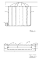
- a roll 1 of photovoltaic (PV) foil comprises a plurality of solar cells 2, arranged in an array. Each row comprises a number of solar cells 2 connected in series by means of interconnects (not detailed separately in Fig. 1). Two bus bars 3 are embedded in the foil.
- An example of a method of manufacturing the roll 1 of foil is set out in more detail in WO 01/78156 .
- An example of a roll 1 of foil that is currently manufactured has a width of about 1.2 m.
- Thin film solar cell foils also known as photovoltaic foils, generally comprise a carrier and a photovoltaic layer composed of a semiconductor material provided between a front electrode comprising a transparent conductive oxide (TCO) at the front of the foil and a back electrode at the back of the foil.
- TCO transparent conductive oxide
- the front electrode is transparent, enabling incident light to reach the semiconductor material, where the incident radiation is converted into electric energy. In this way, light is usable to generate electric current.
- the solar cells 2 are series-connected between the bus bars 3.
- the length of the piece of foil that is cut off from the roll 1 determines the length of each bus bar 3 in the foil.
- the width of a bus bar 3 (in the plane of the foil) is preferably a value in the range of 0.5-1 cm.
- the height is preferably a value in the range of 80-100 ⁇ m.
- a suitable material for the bus bars 3 is aluminium, although another electrically conductive material, e.g. a metal or metal alloy is usable in alternative embodiments.
- a piece of laminated foil 4 comprises a laminate of a PV foil 5 sandwiched between an upper electrically insulating layer 6 and a lower electrically insulating layer 7. Both electrically insulating layers 6,7 are made of plastic.
- the upper layer 6 is thicker than the lower layer 7 in the illustrated embodiment, since it is exposed to the environment. The opposite is true in other variants, depending on the need to stabilise the foil, for instance.
- the piece of laminated foil 4 comprising the laminate of the PV foil 5, and electrically insulating layers 6,7 need not be sandwiched between glass plates.
- the lower layer 7 is preferably adhered directly onto a supporting surface (not shown), in order to provide stability.
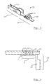
- the connector contact 8 includes a first section 9, including a substantially planar base 10, from which four tines 11 protrude. These tines 11 form contact elements for establishing an electrically conductive connection to a bus bar 3 at a desired point along its length.
- the first section 9 is of a somewhat elongated shape, and is attached to a second section 12 at one longitudinal end. The opposite longitudinal end terminates the connector contact 8.
- the second section 12 includes a female terminal 13, suitable for mating with a male terminal (not shown) of a wire connector.
- the second section 12 includes a terminal for direct attachment to a wire, for example by soldering or crimping onto the wire.
- Suitable wires have a diameter with a value in the range of 2-3 mm, and are included in a single-wire cable.
- the wire is preferably made of between thirty and sixty strands of copper, aluminium, or an alloy thereof, and may be galvanised.
- Insulating cladding is used, with an outer diameter having a value in the range of 5-6 mm.
- Suitable insulating materials include Polyolefins and PTFE.
- Such cables generally have a rated voltage of 1000 V DC, and a rated current of 60 A.
- the connector contact 8 is attached to the piece of laminated foil 4 by pressing the tines 11 into the laminated foil 4, such that they penetrate the laminated foil.
- the base 10 is thus brought into contact with the lower surface of the lower electrically insulating layer 7. In that position, the base 10 is parallel to the plane of the laminated foil, so as to provide extra support.
- the connection is thus stiffened, and the area of connection need not necessarily be adhered to a supporting surface, allowing provision of a recess or hole for accommodating the connector contact and a connector housing (not shown).
- the tines 11 protrude into the piece of laminated foil 4 at an angle to the base 10. Subsequently, the tines 11 are bent back on themselves to bring their tips 15 into contact with the bus bar 3.
- the upper surface of the piece of laminated foil 4, formed by the outer surface of the upper electrically insulating layer 6, is raised only to a minimal extent. This helps prevent shadow-forming, because a housing with a lower profile can be used to shield the protruding tines 11 from the environment.
- the connector contact 8 is then bent, assuming the configuration shown very schematically in Fig. 4.
- the second section 12 is oriented at an angle to the first section 9, preferably substantially perpendicularly to it.
- the longitudinal axis of the second section 12 is at substantially the same angle to the plane of the piece of laminated foil 4.
- the wire is substantially aligned with the longitudinal axis of the terminal 13, so that the wire is lead away from the lower surface of the piece of laminated foil 4.
- the connector contact 8 is bent before being pressed into the piece of laminated foil 4.
- the connector contact 8 shown in Fig. 3 is but one suitable embodiment.
- Other embodiments include a first section with a base from which pyramid-shaped structures with sharp tips protrude. Such tips pierce through the lower electrically insulating layer to contact a bus bar from below. Friction keeps the connector contact attached to the piece of laminated foil 4.
- a soldered connector contact may be used instead of a crimp connector contact or piercing connector contact, but is least preferred because the solder causes a local elevation of the laminated foil when the latter is applied to a supporting surface.
- the invention is not limited to the above-described embodiments, which may be varied within the scope of the claims.
- the invention can also be implemented using other types of foils in which exchange of radiation energy occurs, for example those comprising cells with luminescent Light Emitting Diodes, window foils, foils for a flexible display.
- other types of interaction with the environment may take place through the surface, as in the case of battery foils, for example.
Priority Applications (1)
| Application Number | Priority Date | Filing Date | Title |
|---|---|---|---|
| EP05075734A EP1708309A1 (fr) | 2005-03-30 | 2005-03-30 | Procédé de connexion d'un contact à une couche et ensemble comportant un couche et un contact |
Applications Claiming Priority (1)
| Application Number | Priority Date | Filing Date | Title |
|---|---|---|---|
| EP05075734A EP1708309A1 (fr) | 2005-03-30 | 2005-03-30 | Procédé de connexion d'un contact à une couche et ensemble comportant un couche et un contact |
Publications (1)
| Publication Number | Publication Date |
|---|---|
| EP1708309A1 true EP1708309A1 (fr) | 2006-10-04 |
Family
ID=34938121
Family Applications (1)
| Application Number | Title | Priority Date | Filing Date |
|---|---|---|---|
| EP05075734A Withdrawn EP1708309A1 (fr) | 2005-03-30 | 2005-03-30 | Procédé de connexion d'un contact à une couche et ensemble comportant un couche et un contact |
Country Status (1)
| Country | Link |
|---|---|
| EP (1) | EP1708309A1 (fr) |
Citations (5)
| Publication number | Priority date | Publication date | Assignee | Title |
|---|---|---|---|---|
| US3977757A (en) * | 1975-03-17 | 1976-08-31 | General Motors Corporation | Wipe-in female terminal for printed circuits |
| EP0698943A1 (fr) * | 1994-08-23 | 1996-02-28 | Thomas & Betts Corporation | Assemblage de connecteur de câble d'une section plate à une section ronde |
| FR2785726A1 (fr) * | 1998-11-05 | 2000-05-12 | Whitaker Corp | Assemblage de connexion electrique pour conducteurs souples a feuille mince ou film |
| EP1225661A1 (fr) * | 2001-01-23 | 2002-07-24 | Fci | Dispositif d'amenee de connecteurs et station de sertissage munie d'un tel dispositif |
| WO2003103097A1 (fr) * | 2002-06-04 | 2003-12-11 | Robert Bosch Gmbh | Connecteur electrique a fiches pour etablir une connexion electrique entre une fiche male et un conducteur plat |
-
2005
- 2005-03-30 EP EP05075734A patent/EP1708309A1/fr not_active Withdrawn
Patent Citations (5)
| Publication number | Priority date | Publication date | Assignee | Title |
|---|---|---|---|---|
| US3977757A (en) * | 1975-03-17 | 1976-08-31 | General Motors Corporation | Wipe-in female terminal for printed circuits |
| EP0698943A1 (fr) * | 1994-08-23 | 1996-02-28 | Thomas & Betts Corporation | Assemblage de connecteur de câble d'une section plate à une section ronde |
| FR2785726A1 (fr) * | 1998-11-05 | 2000-05-12 | Whitaker Corp | Assemblage de connexion electrique pour conducteurs souples a feuille mince ou film |
| EP1225661A1 (fr) * | 2001-01-23 | 2002-07-24 | Fci | Dispositif d'amenee de connecteurs et station de sertissage munie d'un tel dispositif |
| WO2003103097A1 (fr) * | 2002-06-04 | 2003-12-11 | Robert Bosch Gmbh | Connecteur electrique a fiches pour etablir une connexion electrique entre une fiche male et un conducteur plat |
Similar Documents
| Publication | Publication Date | Title |
|---|---|---|
| KR100574844B1 (ko) | 판형 가요성 케이블커넥터를 사용하기 위한 방법 및 장치 | |
| KR20050059156A (ko) | 광전도 셀들에 관한 전극, 광전도 셀 및 광전도 모듈 | |
| US8512066B2 (en) | Electric wire connector for press connecting electric wires | |
| JP2010510686A (ja) | 太陽電池モジュールのためのケーブルコネクタ及びその設置方法 | |
| GB2473690A (en) | Electric wire connector | |
| US20110275244A1 (en) | Connector assembly for a photovoltaic module | |
| CN102656748B (zh) | 大电流接触组件以及相应的用于制造大电流接触装置的方法 | |
| US6676459B2 (en) | Conductor connection method, conductor connection structure, and solar cell module having connection structure | |
| JP5819862B2 (ja) | 特別な母線形状を有する太陽電池、前記太陽電池を含む太陽電池配列、および太陽電池を製造するための方法 | |
| CN107681349A (zh) | 电连接器 | |
| JP2012084560A (ja) | 結晶系太陽電池モジュール | |
| JPWO2018180922A1 (ja) | 太陽電池モジュールおよびその製造方法 | |
| US20120167959A1 (en) | Photovoltaic module having a planar cell connector | |
| EP1708309A1 (fr) | Procédé de connexion d'un contact à une couche et ensemble comportant un couche et un contact | |
| US9136626B2 (en) | Electrical connection system | |
| WO2014174407A1 (fr) | Panneau arrière à contact arrière pour modules photovoltaïques avec contacts électriques traversants | |
| US7762835B2 (en) | Electrical contact connecting to a conducting lead embedded in a piece of foil | |
| JP2523867Y2 (ja) | 太陽電池モジュール | |
| JP2017045948A (ja) | 繊維状光発電素子の直列接続構造 | |
| CN113161057A (zh) | 一种柔性扁平电缆及其制备工艺和应用 | |
| US20130032199A1 (en) | Photovoltaic module | |
| CN220439634U (zh) | 太阳能电池模块、组件和光伏系统 | |
| KR102233683B1 (ko) | 와이어를 구비한 슁글드 태양전지 패널 및 그 제조방법 | |
| CN209526103U (zh) | 背接触太阳电池互联结构 | |
| CN117894852A (zh) | 一种光伏组件 |
Legal Events
| Date | Code | Title | Description |
|---|---|---|---|
| PUAI | Public reference made under article 153(3) epc to a published international application that has entered the european phase |
Free format text: ORIGINAL CODE: 0009012 |
|
| AK | Designated contracting states |
Kind code of ref document: A1 Designated state(s): AT BE BG CH CY CZ DE DK EE ES FI FR GB GR HU IE IS IT LI LT LU MC NL PL PT RO SE SI SK TR |
|
| AX | Request for extension of the european patent |
Extension state: AL BA HR LV MK YU |
|
| AKX | Designation fees paid | ||
| REG | Reference to a national code |
Ref country code: DE Ref legal event code: 8566 |
|
| STAA | Information on the status of an ep patent application or granted ep patent |
Free format text: STATUS: THE APPLICATION IS DEEMED TO BE WITHDRAWN |
|
| 18D | Application deemed to be withdrawn |
Effective date: 20070405 |