EP1707855A1 - Bauteil, insbesondere Dicht- und/oder Abschirmteil - Google Patents
Bauteil, insbesondere Dicht- und/oder Abschirmteil Download PDFInfo
- Publication number
- EP1707855A1 EP1707855A1 EP06005464A EP06005464A EP1707855A1 EP 1707855 A1 EP1707855 A1 EP 1707855A1 EP 06005464 A EP06005464 A EP 06005464A EP 06005464 A EP06005464 A EP 06005464A EP 1707855 A1 EP1707855 A1 EP 1707855A1
- Authority
- EP
- European Patent Office
- Prior art keywords
- component according
- connecting part
- recess
- surface part
- partially
- Prior art date
- Legal status (The legal status is an assumption and is not a legal conclusion. Google has not performed a legal analysis and makes no representation as to the accuracy of the status listed.)
- Granted
Links
- 238000007789 sealing Methods 0.000 title claims description 10
- 238000006073 displacement reaction Methods 0.000 claims description 14
- 239000002184 metal Substances 0.000 claims description 4
- 238000012937 correction Methods 0.000 claims 1
- 230000007246 mechanism Effects 0.000 abstract 1
- 210000002105 tongue Anatomy 0.000 description 16
- 239000000463 material Substances 0.000 description 7
- 238000002485 combustion reaction Methods 0.000 description 5
- 230000008646 thermal stress Effects 0.000 description 4
- 239000011324 bead Substances 0.000 description 3
- 238000001816 cooling Methods 0.000 description 3
- 238000009434 installation Methods 0.000 description 3
- 230000000670 limiting effect Effects 0.000 description 3
- 238000012423 maintenance Methods 0.000 description 3
- 230000035515 penetration Effects 0.000 description 3
- 239000003054 catalyst Substances 0.000 description 2
- 239000011248 coating agent Substances 0.000 description 2
- 238000000576 coating method Methods 0.000 description 2
- 238000013461 design Methods 0.000 description 2
- 238000011161 development Methods 0.000 description 2
- 238000010438 heat treatment Methods 0.000 description 2
- 230000001771 impaired effect Effects 0.000 description 2
- 238000009413 insulation Methods 0.000 description 2
- 230000005923 long-lasting effect Effects 0.000 description 2
- 238000000034 method Methods 0.000 description 2
- 230000008569 process Effects 0.000 description 2
- 230000008439 repair process Effects 0.000 description 2
- 229910000639 Spring steel Inorganic materials 0.000 description 1
- 238000005299 abrasion Methods 0.000 description 1
- 230000000712 assembly Effects 0.000 description 1
- 238000000429 assembly Methods 0.000 description 1
- 230000004888 barrier function Effects 0.000 description 1
- 230000008859 change Effects 0.000 description 1
- 230000001419 dependent effect Effects 0.000 description 1
- 230000000694 effects Effects 0.000 description 1
- 239000000446 fuel Substances 0.000 description 1
- 230000007774 longterm Effects 0.000 description 1
- 238000004519 manufacturing process Methods 0.000 description 1
- 239000007769 metal material Substances 0.000 description 1
- 238000012856 packing Methods 0.000 description 1
- 230000002093 peripheral effect Effects 0.000 description 1
- 230000001681 protective effect Effects 0.000 description 1
- 230000002829 reductive effect Effects 0.000 description 1
- 230000000452 restraining effect Effects 0.000 description 1
- 230000002441 reversible effect Effects 0.000 description 1
- 230000035882 stress Effects 0.000 description 1
- 230000003319 supportive effect Effects 0.000 description 1
- 230000007704 transition Effects 0.000 description 1
Images

Classifications
-
- F—MECHANICAL ENGINEERING; LIGHTING; HEATING; WEAPONS; BLASTING
- F16—ENGINEERING ELEMENTS AND UNITS; GENERAL MEASURES FOR PRODUCING AND MAINTAINING EFFECTIVE FUNCTIONING OF MACHINES OR INSTALLATIONS; THERMAL INSULATION IN GENERAL
- F16J—PISTONS; CYLINDERS; SEALINGS
- F16J15/00—Sealings
- F16J15/02—Sealings between relatively-stationary surfaces
- F16J15/06—Sealings between relatively-stationary surfaces with solid packing compressed between sealing surfaces
- F16J15/08—Sealings between relatively-stationary surfaces with solid packing compressed between sealing surfaces with exclusively metal packing
- F16J15/0818—Flat gaskets
- F16J15/0825—Flat gaskets laminated
-
- F—MECHANICAL ENGINEERING; LIGHTING; HEATING; WEAPONS; BLASTING
- F16—ENGINEERING ELEMENTS AND UNITS; GENERAL MEASURES FOR PRODUCING AND MAINTAINING EFFECTIVE FUNCTIONING OF MACHINES OR INSTALLATIONS; THERMAL INSULATION IN GENERAL
- F16J—PISTONS; CYLINDERS; SEALINGS
- F16J15/00—Sealings
- F16J15/02—Sealings between relatively-stationary surfaces
- F16J15/06—Sealings between relatively-stationary surfaces with solid packing compressed between sealing surfaces
- F16J15/08—Sealings between relatively-stationary surfaces with solid packing compressed between sealing surfaces with exclusively metal packing
- F16J15/0818—Flat gaskets
- F16J15/0825—Flat gaskets laminated
- F16J15/0831—Flat gaskets laminated with mounting aids
Definitions
- the invention relates to a component, in particular sealing and / or shielding, consisting of at least partially superimposed surface parts, which are at least partially connected to each other by means of at least one connecting device.
- plastic bottom plates the sound leakage from the engine compartment to Reduce road surface, under certain circumstances, create an effective insulation, is included with the heat in the engine compartment.
- Catalysts are among the sources of heat due to their phase-wise high surface temperature, which in any case may require the use of protective shield barriers (New Materials and Development Tools for Heat Protection in MTZ 12/2001, Cig.72, page 1044ff).
- a pertinent shielding known as a sound insulating heat shield for use in motor vehicles.
- this consists of at least partially superimposed, area formed screen parts, which receive between them an insulating intermediate layer and the outer peripheral side along a common connecting line are connected to each other for fixed connection with each other by a connecting device in the manner of Beading one screen part under cover of the insulating intermediate layer comprises the other screen part in the same attack.
- the known form-fitting connection defines the individual layers or screen parts immovable relative to each other and because of the rigid connection produced, it can cause problems in fixing it, especially in thermal expansion processes for the shielding, especially if the shielding on the edge attacking, angular bracket legs within the Engine compartment is rigidly fixed to local fixed parts.
- the angle-shaped stirrup leg as a fixing means on the intended screw detach from the associated engine components and thus release the component, which in turn can result in appropriate repair and maintenance.
- the known solution is expensive to implement because the flanging is laborious and costly.
- the angle-shaped stirrup legs additionally provide, which also increases the assembly effort in production lines of motor vehicles and motor vehicles.
- a metallic cylinder head gasket is known as a component with a gasket opening having at least one combustion chamber opening as a sealing unit, which has at least two adjacent sheet metal layers as surface parts, of which a first with at least one elastically height deformable, the combustion chamber opening enclosing bead and a second with at least one the bead deformation limiting, surrounding the combustion chamber opening deformation limiting device is provided.
- a cylinder head gasket designed as a flat gasket is known with metallic individual layers as surface parts in which at least one passage opening (combustion chamber opening) is formed.
- This or at least one of the metallic layers is at least partially formed in the form of a wave or sawtooth profiling around the respective combustion chamber opening, wherein at least the position in which the profiling is formed, due to the required very high elasticity limits of a spring steel has to exist the profiling has a deformation limiting device for an additionally formed bead.
- the described sealing system parts in the form of the cylinder head gaskets are fixed peripherally by means of a connecting device regularly in the form of engaging screws on the assignable engine components. If it comes in operation pertinent seals to a heating of the sheet-like sheet material, the individual layers expand under the influence of heat accordingly, possibly even to varying degrees, which leads to thermal stresses in the material with the result that the desired sealing function can be impaired or even to Failure of the cylinder head gasket in areas subject to heavy wear in long-term operation comes.
- the present invention seeks to further improve the known solutions while maintaining their advantages that even with heavy thermal stress a reliable use is ensured and that the solution can be implemented inexpensively at the same time reduced maintenance intensity.
- This object is achieved by a component having the features of claim 1 in its entirety.
- connection means fixed to a surface part, the other surface part engages and engages with this, that at least partially the surface parts are at least one compensation path relative to each other along sliding displacements held displaceable, is a rigid Connection of the individual surface parts, as shown in the prior art, avoided and rather the surface parts can now depending on the thermal situation mutually "slide" each other, without thereby establishing a reliable connection the connection device would be impaired.
- the component according to the invention is preferably at least partially designed as a shielding part, in particular in the manner of a heat shield, due to the permitted relative displacement movement of the surface parts to each other Beul bine on the screen parts can be avoided and they do not break; also not in the area of their definition on other machine or vehicle parts. Since the frictional connection of the surface parts is maintained with the respective displacement possibility in any thermal situation and in any fixing state, can be used by the inventive component this long in such highly thermally stressed zones, for example, directly in the sealing area of a cylinder head gasket, where the previous use Of these components with heat shield effect was not readily possible.
- the component can also be used exclusively as a sealing part, for example in the manner of a cylinder head gasket or in the manner of an exhaust gasket, between the head of an engine and the manifold of an exhaust system and the occurring thermal expansion and stress are in turn compensated by the claimed connection means the surface parts can slide against each other by at least one compensating section, preferably along predetermined displacement directions so as not only to relieve the seal itself, but also the further connection points, with which the component is connected to the other engine or machine components.
- the connection device requires little installation space and the connection device can be produced in a cost-effective manner.
- the respective connecting device has a connecting part which is formed from the respective one surface part integral part of the same, wherein the connecting part engages through an associated recess in the other surface part.
- the connecting part consists of a kind of spring tongue, which is at least partially bent out of the one surface part and the drive part consists of a transverse web, which passes through the recess at least partially transverse to the longitudinal direction of the connecting part.
- a locking of the surface parts reachable to each other which on the one hand facilitates the assembly of the surface parts during assembly and further is defined as a starting state, in which the surface parts can move back defined during a cooling process.
- a relative movement of the surface parts relative to each other can take place. If the connecting part is formed as a spring tongue, this is at least partially frictionally against the wall of the assignable surface part, so that an unwanted, independent release of the connecting device is avoided even in a pre-assembled state.
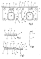
- the component shown as a whole in Figure 3 is constructed in particular in the manner of a sealing member 10, consisting of two superimposed surface parts 12,14, wherein in Figure 1, the upper surface portion 12 is shown, as well as the Figure 3 in the view reproduces, and the underlying, lower surface portion 14 as shown in FIG. 2 is substantially covered over the entire surface by the surface part 12 in Figure 3.
- the two surface parts 12, 14 are connected to one another by means of two connecting devices designated 16 as a whole. 2 engages in the assembly state according to the illustration of Figure 3, the other surface part 12 such that the surface parts 12,14 by at least one compensation path relative to each other along preferred Verschieregonne, as indicated in Figure 3 by way of example with a double arrow Z, are held displaceably.
- the respective connecting device 16 has a connecting part in the manner of a spring tongue 18, which is formed from the respective one surface part 14 (see FIG.2) integral part of the same, wherein the connecting part in the assembled state each have an associated recess 20 in the other surface part 12 (Fig. see Fig.1) passes through.
- the respective recess 20 according to FIG. 1 has a drive part in the form of a transverse web 22, which as latching means in a starting position according to the illustrations according to FIGS.
- the respective connecting part in the form of the spring tongue 18 in the displacement directions Z in a detachable manner Holds detent position and in a compensating position, not shown, which is different from the starting position, abandoning the detent position allows the relative movement of the two surface parts 12,14 to the respective compensation path whose distance results from the thermally present conditions.
- the spring tongue 18 is cut or punched out of the one surface part 14, wherein a U-shaped penetration space 24 is provided, in which the connecting part in the form of the spring tongue 18 can engage under the provision of a restoring force.
- the respective spring tongue 18 is mounted in the assignable penetration space 24 such that the spring tongue 18 is substantially flush with the underside 26 of the surface part 14 on its underside and stands on the front side 28 of the surface part 14 the spring tongue 18 at least partially with a certain projection before.
- the spring tongue 18 at the edge end of the passage space 24 via a pivot point 30 resiliently connected to the other surface material of the surface part 14.
- the surface part 12 is viewed in the direction of view of FIG. 1, placed in such a way on the surface part 14 according to the illustration according to FIG. 2, in the direction of looking at FIGS. 1 and 2 Seen around a left offset distance, which compensates to the right causes the connecting part with its free end in the form of a projection 32 initially coming from the bottom 34 of the surface part 12, the right part of the recess 20 passes through, then to override of the crosspiece 22 on the Top 36 of the surface part 12th to drive over the left part 20 'of the recess, wherein a projection 32 subsequent expression 38 from above into the recess 20' engages.
- a further oppositely directed expression 40 which is arranged between the articulation point 30 and the first expression 38 in the connecting part in the form of the spring tongue 18 .
- the projection 32 of the connecting part is held at its transition point to the expression 38 in a supportive engagement with an edge boundary wall 42 of the recess 20 '.
- a third locking means may be formed by the articulation point 30 of the connecting part itself, which may be supported in a mounting state on a further boundary wall 44 of the surface part 12. For this purpose, as viewed in the direction of FIG. 3, the surface part 12 would have to be displaced into its extremely left-hand position in the stationary position of the surface part 14.
- Both surface parts 12, 14 have pairs of congruent passage openings 46, which are sealed by a ring seal 48.
- the pertinent annular seal 48 is recessed in the direction of the passage opening 46 with a surface area 50 (see sectional view according to FIG. 4) and thus also in the preassembled state in direct contact with the front or top side 28 of the surface part 14, whereas the area near the passage opening 46 and outside of the region 50, the ring seal 48, at least in the pre-assembly state, has a spacing in the form of a cavity 52 between the front side 28 of the surface part 14 and the bottom side 34 of the surface part 12.
- Existing ring seals made of metallic material are common, so that will not be discussed in more detail here at this point.
- the respective passage opening 46 is at the edge of the surface material of the respective surface portion 12,14 includes the corner engaging openings 54,56 for fixing means, such as fixing screws, not shown, wherein the diameter of the engaging holes 54 of a surface portion 14 is smaller than the diameter of In this case, the diameter difference between the engagement openings 54, 56 measured in one direction such that it corresponds in any case to the length of the maximum compensation path provided. If the two surface parts 12,14 their installation position as shown in FIG 3 and corresponds to this installation position initially the initial state of Figure 5, so are the other mutually facing and assignable engagement holes 54 and 56 in coaxial arrangement without further thermal stress and for a penetration of a corresponding fixing means, such as a fixing screw provided.
- the screw is dimensioned such that the screw thread fits through the engagement opening 54 of smaller diameter and the screw head is in any case chosen such that it can overlap with a predetermined projection, the larger engagement opening 56.
- other fixing means such as rivets od. Like., Can be used instead of the indicated screw. It is important, however, that the fixing means is selected in such a way, in particular by its geometrical dimensions, that when the surface parts 12, 14 are displaced relative to each other, the larger of the engagement openings 56 remains at least partially covered.
- the component according to FIG. 3 is installed in the assembled state, for example in a motor vehicle engine, and heating of the surface parts 12, 14 occurs during operation of the engine, they expand if necessary also in varying degrees along their surface direction and the surface part material shifts below the fixing heads (screw heads) of the fixing means accordingly.
- a preferred direction of the pertinent thermal thermal expansion corresponds to the respective displacement direction after the double arrow Z. If the surface parts 12, 14 now expand, it becomes clear from FIG. 5 that the connection device 16 can follow the corresponding compensating movement without the connection between the two Surface parts 12,14 would be affected even.
- a compensating section is thus provided via the connecting device along the double arrow direction Z, which permits thermal expansions, wherein frictional slippage of the surface parts 12, 14 to each other damaging force discharges into the region of the ring seal 48 are avoided as well as in the region of the fixing points via the engagement openings 54,56.
- the ring seal 48 can follow the pertinent displacement movement in each case since, according to the sectional illustration according to FIG. 4, the seal is selected such that the surface parts 12, 14 can likewise slide flush over their facing sides 28, 34. Since the longitudinal compensation possibility not only acts in the longitudinal axis of the respective connecting device 16, but can cover the entire surface area of the surface parts 12,14, so far a secure compensation option is created, even if it might occur in other directions due to thermal stresses forces or spikes.
- a further decoupling is provided by the fact that a center corridor 62 is introduced into the two surface regions 12, 14, which decouples opposing surface regions 64 of the two surface parts 12, 14 on both sides.
- the addressed center corridor 62 passes through the surface parts 12, 14 in the transverse direction until it abuts with its bottom 66 against the common longitudinal axis of the two connection devices 16.
- Such is the center corridor 62 a gap compensation movement is possible in which, within predefinable limits, the gap entrance of the corridor 64, which is arranged opposite the base 66, can expand under heat.
- the center corridor 62 assumes its initial position according to FIGS. 1,2 and 3 again.
- a further, not shown, for example, bellows-like Kompensator might be present, which also serves the length compensation in heat input.
- the solution shown in the figures can be provided with the omission of the central corridor 62 for only one passage opening 46; Preferably, however, as shown, a plurality of through holes, more than two through holes 46, provided with corresponding ring seals 48 and the described thermal compensation possibility.
- the surface part 12 on its upper side, folded has a further surface part 70, which can serve in particular for thermal shielding when heat is applied.
- the surface parts 12,14 are formed as sheet metal blanks or Blechumformmaschine and single-layered.
- the compensation device according to the invention can also be used optionally for multi-layered surface parts.
- the folded surface patch 70 may also serve to connect other, not shown heat shields with said component.
- the component itself may be formed in the manner of a heat shield and then connect the heat shield function with a Fluidabdichtfunktion.
- the solution according to the invention is intended in particular for sealing the area between the head of a motor unit and the line system of a Exhaust manifold can be used. Due to the center corridor 62 with web arrangement 68, it is moreover ensured that vibrations introduced largely remain in the respective surface area 64 and do not readily change into other adjacent area areas.
- the mutually facing wall parts of the surface parts 12,14 are provided with an abrasion-resistant coating, it being sufficient to provide a wall portion of a surface portion 12 or 14 with a pertinent coating (not shown).
Landscapes
- Engineering & Computer Science (AREA)
- General Engineering & Computer Science (AREA)
- Mechanical Engineering (AREA)
- Gasket Seals (AREA)
- Specific Sealing Or Ventilating Devices For Doors And Windows (AREA)
- Exhaust Silencers (AREA)
Abstract
Description
- Die Erfindung betrifft ein Bauteil, insbesondere Dicht- und/oder Abschirmteil, bestehend aus zumindest teilweise übereinanderliegenden Flächenteilen, die zumindest teilweise mittels mindestens einer Verbindungseinrichtung miteinander verbunden sind.
- Während die Wärmeentwicklung beispielsweise eines sparsamen leistungsoptimierten Dieselmotors am Zylinderkurbelwellengehäuse sehr gering sein kann, gilt das für "heiße Zonen", wie bei Krümmer, Turbolader, Katalysator etc., keineswegs. Durch die immer kompaktere Konstruktion der Motoren geraten zunehmend Komponenten in enge Nachbarschaft, die thermisch nicht "kompatibel" sind. Demgemäß ist es notwendig, mit sog. Abschirmteilen, wie Hitzeschildern, thermische Motorenkomponenten gegenüber angrenzenden wärmeempfindlichen Aggregaten, wie Sensoren, Kraftstoffleitungen, Druckdosen, Karosserieteilen etc., zu schützen. Die Situation wird durch den Kompaktbau auch insofern verschärft, dass die hohe Packungsdichte der Aggregate den kühlenden Luftstrom im Motorraum einengt. Auch Lärmschutzmaßnahmen können dazu mit beitragen. So können beispielsweise Kunststoffbodenplatten, die den Schallaustritt vom Motorraum zur Fahrbahn vermindern sollen, unter Umständen eine wirkungsvolle Isolation erzeugen, mit der Wärme im Motorraum eingeschlossen wird. Katalysatoren zählen wegen ihrer phasenweisen hohen Oberflächentemperatur zu den Hitzequellen, die den Einsatz von schützenden Schildbarrieren jedenfalls erforderlich machen können (Neue Werkstoffe und Entwicklungs-Tools für den Hitzeschutz in MTZ 12/2001, Jahrg.72, Seite 1044ff).
- Durch die
DE 102 47 641 B3 ist ein dahingehendes Abschirmteil als schalldämmendes Hitzeschild für eine Anwendung bei Kraftfahrzeugen bekannt. Um bei dem bekannten Bauteil die Schalldämmung zu verbessern, besteht dieses aus zumindest teilweise übereinanderliegenden, flächig ausgebildeten Schirmteilen, die zwischen sich eine isolierende Zwischenschicht aufnehmen und die zur festen Verbindung miteinander außenumfangsseitig entlang einer gemeinsamen Verbindungslinie miteinander verbunden sind, indem als Verbindungseinrichtung in der Art einer Umbördelung das eine Schirmteil unter Übergriff der isolierenden Zwischenschicht das andere Schirmteil in demselben Übergriff umfaßt. - Die dahingehend bekannte Formschlußverbindung legt die einzelnen Lagen oder Schirmteile relativ zueinander unbewegbar fest und aufgrund der derart starr hergestellten Verbindung kann es insbesondere bei thermischen Ausdehnungsvorgängen für das Abschirmteil zu Problemen bei dessen Festlegung kommen, insbesondere, wenn das Abschirmteil über randseitig angreifende, winkelförmige Bügelschenkel innerhalb des Motorraumes an dortigen feststehenden Teilen starr festgelegt ist. Neben einem eventuellen Aufwerfen des mehrlagigen, abschirmenden Bauteils mit gegebenenfalls Beulen und Einreißen des Hitzeschildmaterials, was zum Versagen desselben führen kann, ist auch nicht auszuschließen, dass die winkelförmigen Bügelschenkel als Festlegemittel sich über die vorgesehene Schraubverbindung von den zugeordneten Motorenbaukomponenten lösen und dergestalt das Bauteil freigeben, was wiederum entsprechende Reparatur- und Wartungsarbeiten nach sich ziehen kann. Auch ist die bekannte Lösung teuer in der Realisierung, da die Umbördelung arbeits- und kostenintensiv ist. Ferner sind beim Einbau des bekannten Bauteils in Kraftfahrzeuge die winkelförmigen Bügelschenkel zusätzlich bereit zu stellen, was auch insoweit den Montageaufwand in Produktionslinien von Kraftfahrzeugen und Kraftfahrzeugmotoren erhöht.
- Durch die
EP-A-1 298 365 ist eine metallische Zylinderkopfdichtung als Bauteil bekannt mit einer mindestens eine Brennraumöffnung als Durchgangsöffnung aufweisenden Dichtungsplatte als Dichtungseinheit, welche mindestens zwei aneinanderliegende Metallblechlagen als Flächenteile aufweist, von denen eine erste mit mindestens einer elastisch höhenverformbaren, die Brennraumöffnung umschließenden Sicke und eine zweite mit mindestens einer die Sickenverformung begrenzenden, die Brennraumöffnung umgebenden Verformungsbegrenzungseinrichtung versehen ist. - Durch die
WO 01/96768 - Die beschriebenen Dichtsystemteile in Form der Zylinderkopfdichtungen werden randseitig mittels einer Verbindungseinrichtung regelmäßig in Form von Eingriffsschrauben an den zuordenbaren Motorenbaukomponenten festgelegt. Kommt es im Betrieb dahingehender Dichtungen zu einer Erwärmung des flächigen Blechmaterials, dehnen sich die Einzellagen unter dem Wärmeeinfluß entsprechend aus, gegebenenfalls sogar in unterschiedlichem Maße, was zu Wärmespannungen im Material führt mit der Folge, dass die angestrebte Dichtfunktion beeinträchtigt werden kann oder es gar zu einem Versagen der Zylinderkopfdichtung an besonders beanspruchten Bereichen im lang andauernden Betrieb kommt.
- Ausgehend von diesem Stand der Technik liegt der Erfindung die Aufgabe zugrunde, die bekannten Lösungen unter Beibehalten ihrer Vorteile dahingehend weiter zu verbessern, dass auch bei starker thermischer Beanspruchung ein funktionssicherer Gebrauch sichergestellt ist und dass sich die Lösung kostengünstig realisieren läßt bei gleichzeitig verringerter Wartungsintensität. Eine dahingehende Aufgabe löst ein Bauteil mit den Merkmalen des Patentanspruches 1 in seiner Gesamtheit.
- Dadurch, dass gemäß dem kennzeichnenden Teil des Patentanspruches 1 die jeweilige Verbindungseinrichtung an einem Flächenteil festgelegt das andere Flächenteil derart durchgreift und mit diesem in Eingriff steht, dass zumindest teilweise die Flächenteile um mindestens eine Ausgleichsstrecke relativ gegeneinander entlang von Verschieberichtungen verschiebbar gehalten sind, ist eine starre Verbindung der einzelnen Flächenteile, wie im Stand der Technik aufgezeigt, vermieden und vielmehr können die Flächenteile nun in Abhängigkeit von der thermischen Situation gegenseitig aneinander "abgleiten", ohne dass hierdurch eine verläßliche Verbindung über die Verbindungseinrichtung beeinträchtigt wäre. Aufgrund der zugelassenen relativen Verschiebebewegung der Flächenteile zueinander um eine jeweilige Ausgleichsstrecke ist ein thermischer Ausgleich geschaffen, der die Einleitung von Kraft- oder Spannungsspitzen im festgelegten Montagezustand vermeiden hilft, so dass die Verbindung entlastet ist, was einen funktionssicheren, lang andauernden Betrieb des Bauteils gewährleistet und Wartungs-oder Reparaturintervalle reduzieren hilft.
- Sofern das erfindungsgemäße Bauteil vorzugsweise zumindest teilweise als Abschirmteil, insbesondere in der Art eines Hitzeschildes konzipiert ist, lassen sich aufgrund der zugelassenen relativen Verschiebebewegung der Flächenteile zueinander Beuleffekte an den Schirmteilen vermeiden und diese reißen nicht ein; auch nicht im Bereich ihrer Festlegung an sonstigen Maschinen- oder Fahrzeugteilen. Da bei jeder thermischen Situation und in jedem Festlegezustand die reibschlüssige Verbindung der Flächenteile mit der jeweiligen Verschiebemöglichkeit erhalten bleibt, läßt sich durch das erfindungsgemäße Bauteil dieses auch in solchen hoch thermisch beanspruchten Zonen lang andauernd einsetzen, beispielsweise unmittelbar im Dichtungsbereich einer Zylinderkopfdichtung, wo der bisherige Einsatz von dahingehenden Bauteilen mit Hitzeschildwirkung nicht ohne weiteres möglich war. Unabhängig hiervon läßt sich das Bauteil auch ausschließlich als Dichtteil, beispielsweise in der Art einer Zylinderkopfdichtung oder in der Art einer Abgasdichtung, zwischen dem Kopf eines Motors und dem Krümmer eines Abgassystems einsetzen und die auftretenden Wärmedehnungen und Spannungen werden wiederum dadurch kompensiert, dass die beanspruchte Verbindungseinrichtung die Flächenteile um mindestens eine Ausgleichsstrecke gegeneinander abgleiten läßt, vorzugsweise entlang von definiert vorgegebenen Verschieberichtungen, um dergestalt nicht nur die Dichtung selbst zu entlasten, sondern auch die weiteren Verbindungsstellen, mit denen das Bauteil mit den sonstigen Motoren- oder Maschinenkomponenten verbunden ist.
- Die erfindungsgemäße Bauteillösung benötigt wenig Einbauraum und die Verbindungseinrichtung läßt sich in kostengünstiger Weise herstellen. Vorzugsweise ist hierzu vorgesehen, dass die jeweilige Verbindungseinrichtung ein Verbindungsteil aufweist, das aus dem jeweiligen einen Flächenteil gebildet einstückiger Bestandteil desselben ist, wobei das Verbindungsteil eine zugeordnete Aussparung im anderen Flächenteil durchgreift. Vorzugsweise besteht dabei des weiteren das Verbindungsteil aus einer Art Federzunge, die zumindest teilweise aus dem einen Flächenteil ausgebogen ist und das Ansteuerteil besteht aus einem Quersteg, der die Aussparung zumindest teilweise quer zur Längsausrichtung des Verbindungsteils durchgreift. Aufgrund dieser Ausgestaltung ist zumindest in einer Ausgangslage, bei der die Relativbewegung der Flächenteile zueinander Null ist oder gegen Null geht, eine Verrastung der Flächenteile zueinander erreichbar, was zum einen das Zusammenfügen der Flächenteile während der Montage erleichtert und des weiteren ist dergestalt ein Ausgangszustand definiert, in dem die Flächenteile sich bei einem Abkühlvorgang definiert zurückbewegen können. Insbesondere kann ausgehend von der Ausgangslage und mithin von dem definierten Rasteingriff nach entgegengesetzten Richtungen eine Relativbewegung der Flächenteile zueinander erfolgen. Sofern das Verbindungsteil als Federzunge ausgebildet ist, liegt diese zumindest in Teilbereichen kraftschlüssig an der Wandung des zuordenbaren Flächenteils an, so dass ein ungewolltes, selbständiges Lösen der Verbindungseinrichtung auch in einem Vormontagezustand vermieden ist.
- Weitere vorteilhafte Ausführungsformen des erfindungsgemäßen Bauteils sind Gegenstand der sonstigen Unteransprüche.
- Im folgenden wird das erfindungsgemäße Bauteil anhand eines Ausführungsbeispiels nach der Zeichnung näher erläutert. Dabei zeigen in prinzipieller und nicht maßstäblicher Darstellung die
- Fig.1
- eine stirnseitige Draufsicht auf ein erstes Flächenteil mit Aussparungen für ein jeweils zuordenbares Verbindungsteil der Verbindungseinrichtung;
- Fig.2
- eine der Fig.1 entsprechende Darstellung eines weiteren zweiten Flächenteils, das mit zu den Aussparungen korrespondierenden Verbindungsteilen in Form von Federzungen versehen ist;
- Fig.3
- eine den Fig.1 und 2 entsprechende Darstellung im Zusammenbauzustand des Bauteils, bei dem das Flächenteil der Fig.1 auf das Flächenteil nach der Fig.2 aufgelegt und dergestalt mit diesem verbunden ist;
- Fig.4
- einen Schnitt längs der Linie I - I in Fig.3;
- Fig.5
- einen Schnitt längs der Linie II - II in Fig.3; und
- Fig.6
- eine Seitendarstellung auf das Flächenteil nach der Fig.1, gesehen dort entlang der Pfeilrichtung X.
- Das in der Fig.3 als Ganzes dargestellte Bauteil ist insbesondere in der Art eines Dichtteils 10 aufgebaut, bestehend aus zwei übereinanderliegenden Flächenteilen 12,14, wobei in der Fig.1 das obere Flächenteil 12 gezeigt ist, wie es auch die Fig.3 in der Ansicht wiedergibt, und das darunterliegende, untere Flächenteil 14 gemäß der Darstellung nach der Fig.2 ist im wesentlichen durch das Flächenteil 12 in der Fig.3 ganzflächig abgedeckt. Wie die Fig.3 des weiteren zeigt, sind die beiden Flächenteile 12,14 mittels zweier als Ganzes mit 16 bezeichneter Verbindungseinrichtungen miteinander verbunden. Die jeweilige Verbindungseinrichtung 16 ist gemäß der Darstellung nach der Fig.2 an dem Flächenteil 14 festgelegt und durchgreift im Zusammenbauzustand gemäß der Darstellung nach der Fig.3 das andere Flächenteil 12 derart, dass die Flächenteile 12,14 um mindestens eine Ausgleichsstrecke relativ gegeneinander entlang von bevorzugten Verschieberichtungen, wie in der Fig.3 exemplarisch mit einem Doppelpfeil Z angedeutet, verschiebbar gehalten sind.
- Die jeweilige Verbindungseinrichtung 16 weist ein Verbindungsteil in der Art einer Federzunge 18 auf, das aus dem jeweiligen einen Flächenteil 14 (vgl. Fig.2) gebildet einstückiger Bestandteil desselben ist, wobei das Verbindungsteil im Montagezustand jeweils eine zugeordnete Aussparung 20 im anderen Flächenteil 12 (vgl. Fig.1) durchgreift. Die jeweilige Aussparung 20 nach der Fig.1 weist ein Ansteuerteil in Form eines Quersteges 22 auf, das als Rastmittel in einer Ausgangslage gemäß den Darstellungen nach den Fig.3 und 5 das jeweilige Verbindungsteil in Form der Federzunge 18 in den Verschieberichtungen Z in einer lösbaren Raststellung hält und in einer nicht näher dargestellten Ausgleichslage, die von der Ausgangslage verschieden ist, unter Aufgabe der Raststellung die Relativbewegung der beiden Flächenteile 12,14 um die jeweilige Ausgleichsstrecke zuläßt, deren Wegstrecke sich aus den thermisch vorliegenden Verhältnissen ergibt.
- Die Federzunge 18 ist aus dem einen Flächenteil 14 ausgeschnitten oder ausgestanzt, wobei ein U-förmiger Durchgriffsraum 24 geschaffen ist, in dem das Verbindungsteil in Form der Federzunge 18 unter Aufbieten einer Rückstellkraft eingreifen kann. Im Vormontagezustand gemäß der Darstellung nach der Fig.2 ist die jeweilige Federzunge 18 in dem zuordenbaren Durchgriffsraum 24 derart angebracht, dass die Federzunge 18 an ihrer Unterseite im wesentlichen bündig mit der Unterseite 26 des Flächenteils 14 abschließt und auf der Vorderseite 28 des Flächenteils 14 steht die Federzunge 18 zumindest teilweise mit einem gewissen Überstand vor. Ferner ist die Federzunge 18 am randseitigen Ende des Durchgriffsraums 24 über eine Anlenkstelle 30 federnd nachgiebig mit dem sonstigen Flächenmaterial des Flächenteils 14 verbunden. Befinden sich die beiden Flächenteile 12,14 in ihrer Einbaulage gemäß der Darstellung nach der Fig.3, ist nach beiden Seiten, also nach beiden Verschieberichtungen Z hin, bezogen auf die Längsausrichtung des jeweiligen Verbindungsteils in Form der Federzungen 18, dieses unter Aufgabe seiner Raststellung gemäß der Darstellung nach der Fig.5 um eine vorgebbare Ausgleichsstrecke verschiebbar geführt, wobei entlang der gesamten Ausgleichsstrecke das Ansteuerteil in Form des Quersteges 22 in Anlage mit dem Verbindungsteil bleibt.
- Um den Montagezustand nach der Fig.3 zu erreichen, wird das Flächenteil 12 in Blickrichtung auf die Fig.1 gesehen, dergestalt auf das Flächenteil 14 gemäß der Darstellung nach der Fig.2 aufgesetzt, und zwar in Blickrichtung auf die Fig. 1 und 2 gesehen um eine linke Versatzstrecke, die nach rechts ausgeglichen bewirkt, dass das Verbindungsteil mit seinem freien Ende in Form eines Vorsprunges 32 zunächst von der Unterseite 34 des Flächenteils 12 kommend den rechten Teil der Aussparung 20 durchgreift, um dann nach Übergriff des Quersteges 22 auf der Oberseite 36 des Flächenteils 12 den linken Teil 20' der Aussparung zu überfahren, wobei eine dem Vorsprung 32 nachfolgende Ausprägung 38 von oben her in die Aussparung 20' eingreift. In der dahingehenden Raststellung, wie sie der Darstellung nach der Fig.5 entspricht, untergreift dann der Quersteg 22 des Flächenteiles 12 eine weitere entgegengesetzt gerichtete Ausprägung 40, die zwischen der Anlenkstelle 30 und der ersten Ausprägung 38 im Verbindungsteil in Form der Federzunge 18 angeordnet ist. Ferner ist bei der dahingehenden Raststellung nach der Fig.5 der Vorsprung 32 des Verbindungsteils an seiner Übergangsstelle zur Ausprägung 38 in stützender Anlage zu einer randseitigen Begrenzungswand 42 der Aussparung 20' gehalten. Des weiteren kann ein drittes Rastmittel durch die Anlenkstelle 30 des Verbindungsteils selbst gebildet sein, das sich in einem Montagezustand an einer weiteren Begrenzungswand 44 des Flächenteils 12 abstützen kann. Hierzu müßte in Blickrichtung auf die Fig.3 gesehen bei stationärer Lage des Flächenteils 14 das Flächenteil 12 in seine äußerst linke Lageposition verschoben werden.
- Beide Flächenteile 12,14 weisen paarweise miteinander deckungsgleiche Durchgangsöffnungen 46 auf, die von einer Ringdichtung 48 abgedichtet sind. Die dahingehende Ringdichtung 48 ist mit einem Flächenbereich 50 (vgl. Schnittdarstellung nach der Fig.4) in Richtung der Durchgangsöffnung 46 vertieft ausgebildet und mithin auch im Vormontagezustand in unmittelbarer Anlage mit der Vorder- oder Oberseite 28 des Flächenteils 14, wohingegen randsbereichsnah zur Durchgangsöffnung 46 und außerhalb des Bereiches 50 die Ringdichtung 48 zumindest im Vormontagezustand teilflächenweise einen Abstand in Form eines Hohlraumes 52 zwischen Vorderseite 28 des Flächenteils 14 und Unterseite 34 des Flächenteils 12 aufweist. Dahingehende Ringdichtungen aus metallischem Werkstoff sind üblich, so dass an dieser Stelle hierauf nicht mehr näher eingegangen wird.
- Die jeweilige Durchgangsöffnung 46 ist randseitig von dem Flächenmaterial des jeweiligen Flächenteils 12,14 umfaßt, das eckweise Eingriffsöffnungen 54,56 für Festlegemittel, wie nicht näher dargestellte Festlegeschrauben, aufweist, wobei der Durchmesser der Eingriffsöffnungen 54 des einen Flächenteils 14 kleiner ist als der Durchmesser der zuordenbaren Eingriffsöffnungen 56 des anderen Flächenteils 12. Dabei ist der Durchmesserunterschied zwischen den Eingriffsöffnungen 54, 56 in einer Richtung gemessen derart, dass sie jedenfalls der Länge der maximal vorgesehen Ausgleichsstrecke entspricht. Nehmen die beiden Flächenteile 12,14 ihre Einbaulage gemäß der Darstellung nach der Fig.3 ein und entspricht diese Einbaulage zunächst dem Ausgangszustand nach der Fig.5, so sind ohne weitere thermische Beanspruchung die einander zugewandten und zuordenbaren Eingriffsöffnungen 54 und 56 in koaxialer Anordnung zueinander und für einen Durchgriff eines korrespondierenden Festlegemittels, wie einer Festlegeschraube, vorgesehen. Die Schraube ist in ihren Abmessungen derart gewählt, dass das Schraubengewinde durch die Eingriffsöffnung 54 kleineren Durchmessers paßt und der Schraubenkopf ist jedenfalls derart gewählt, dass er mit einem vorgebbaren Überstand die größere Eingriffsöffnung 56 übergreifen kann. Anstelle der aufgezeigten Schraubverbindung können natürlich auch andere Festlegemittel, wie Nietverbindungen od. dgl., zum Einsatz kommen. Wichtig ist jedoch, dass das Festlegemittel derart gewählt ist, insbesondere von seinen geometrischen Abmessungen her, dass bei einer etwaigen Verschiebung der Flächenteile 12,14 zueinander die größere der Eingriffsöffnungen 56 zumindest teilweise überdeckt bleibt.
- Ist das Bauteil nach der Fig.3 im Montagezustand, beispielsweise bei einem Kraftfahrzeugmotor, eingebaut und kommt es beim Betrieb des Motors zu einer Erwärmung der Flächenteile 12,14, dehnen diese sich gegebenenfalls auch in unterschiedlichem Maße entlang ihrer Flächenrichtung aus und das Flächenteilmaterial verschiebt sich unterhalb der Festlegeköpfe (Schraubenköpfe) der Festlegemittel entsprechend. Eine bevorzugte Richtung der dahingehenden thermischen Wärmeausdehnung entspricht der jeweiligen Verschieberichtung nach dem Doppelpfeil Z. Dehnen sich die Flächenteile 12,14 nun aus, wird anhand der Fig.5 deutlich, dass die Verbindungseinrichtung 16 der dahingehenden Ausgleichsbewegung nachfolgen kann, ohne dass die Verbindung zwischen den Flächenteilen 12,14 selbst beeinträchtigt wäre.
- Kommt es aufgrund thermischen Einflusses (Motorwärme) zu einer relativen Verschiebebewegung der Flächenteile 12,14 zueinander in einer Richtung, bei der in Blickrichtung auf die Fig.5 gesehen das Flächenteil 14 gegenüber dem Flächenteil 12 nach rechts bewegt wird, hebt der Quersteg 22 über die Rampe 58 die Federzunge 18 an und die Unterseite der einen Ausprägung 38 kommt in Anlage mit der Oberseite des Quersteges 22. Die dahingehende Ausgleichsbewegung ist so lange möglich, bis eben über die Festlegemittel (Schrauben) der Durchmesserunterschied in mindestens einer Richtung zwischen den jeweils zuordenbaren Eingriffsöffnungen 54,56 erreicht ist, wobei in der Praxis eine dahingehende maximale Längenausdehnung nicht zwingend vorkommen muss. Die dahingehende Bewegung um die Ausgleichsstrecke, die durch die Geometrie der Federzunge 18 in Grenzen vorgebbar ist, stellt sich auch ein, wenn das Flächenteil 14 seine Lage in der Fig.5 beibehält und das andere Flächenteil 12 in Blickrichtung auf die Fig.5 gesehen sich relativ gesehen nach links bewegt.
- In umgekehrter Verschieberichtung entlang des Doppelpfeils Z, wenn also beispielsweise bei stationär angeordnetem Flächenteil 12 sich das Flächenteil 14 in Blickrichtung auf die Fig.5 gesehen nach links bewegt, fährt die Oberseite des Quersteges 22 entlang der weiteren Rampe 60 im Bereich der zweiten Ausprägung 40, so dass insoweit gleichfalls eine Ausgleichsbewegung solange möglich ist, gegebenenfalls unter Bewegung der Federzunge 18, bis der rampenartige Anstieg 60 derart steil wird, dass eine definierte Rückhaltekraft definiert ist, die die Flächenteile 12,14 in Richtung ihrer Ausgangslage nach der Fig.5 zu "ziehen" sucht. Wie die obigen Ausführungen verdeutlichen, ist somit über die Verbindungseinrichtung entlang der Doppelpfeilrichtung Z eine Ausgleichsstrecke geschaffen, die thermische Ausdehnungen ermöglicht, wobei durch reibschlüssiges Abgleiten der Flächenteile 12,14 aneinander schädigende Krafteinleitungen in den Bereich der Ringdichtung 48 ebenso vermieden sind wie im Bereich der Festlegestellen über die Eingriffsöffnungen 54,56. Insbesondere kann die Ringdichtung 48 der dahingehenden Verschiebebewegung jeweils nachfolgen, da gemäß der Schnittdarstellung nach der Fig.4 die Dichtung derart gewählt ist, dass bündig die Flächenteile 12,14 gleichfalls über ihre zugewandten Seiten 28,34 abgleiten können. Da die Längsausgleichsmöglichkeit nicht nur in der Längsachse der jeweiligen Verbindungseinrichtung 16 wirkt, sondern den gesamten Flächenbereich der Flächenteile 12,14 abdecken kann, ist insoweit eine sichere Kompensationsmöglichkeit geschaffen, auch wenn gegebenenfalls in anderen Richtungen aufgrund von Wärmespannungen Kräfte- oder Spannungsspitzen auftreten sollten.
- Eine weitere Entkopplung ist bei der gezeigten Lösung nach Fig.3 dadurch vorhanden, dass in die beiden Flächenbereiche 12,14 ein Mittenkorridor 62 eingebracht ist, der beidseitig gegenüberliegende Flächenbereiche 64 der beiden Flächenteile 12,14 voneinander entkoppelt. Der angesprochene Mittenkorridor 62 durchgreift dabei in Querrichtung die Flächenteile 12,14 derart, bis er mit seinem Grund 66 an die gemeinsame Längsachse der beiden Verbindungseinrichtungen 16 anstößt. Dergestalt ist über den Mittenkorridor 62 eine Spaltausgleichsbewegung möglich, bei der in vorgebbaren Grenzen der Spalteingang des Korridors 64, der gegenüberliegend dem Grund 66 angeordnet ist, unter Wärme sich erweitern kann. Bei Abkühlung versuchen dann die Flächenteile 12,14 ihren jeweiligen Ausgangszustand wieder einzunehmen, bei dem dann auch der Mittenkorridor 62 seine Ausgangslage nach den Fig. 1,2 und 3 wieder einnimmt. Ferner kann in der Stegfläche 68, die an den Grund 66 anschließt, eine weitere, nicht näher dargestellte, beispielsweise balgartige Kompensatoreinrichtung vorhanden sein, die zusätzlich dem Längenausgleich bei Wärmeeintrag dient.
- Die in den Figuren gezeigte Lösung kann unter Wegfall des Mittenkorridors 62 für nur eine Durchgangsöffnung 46 vorgesehen sein; vorzugsweise werden jedoch, wie dargestellt, mehrere Durchgangsöffnungen, auch mehr als zwei Durchgangsöffnungen 46, mit entsprechenden Ringdichtungen 48 sowie der beschriebenen thermischen Ausgleichsmöglichkeit versehen. Gemäß den Darstellungen nach den Fig.1,3 und 6 weist in Blickrichtung auf die Figuren das Flächenteil 12 an seiner Oberseite, abgekantet ein weiteres Flächenteil 70 auf, das insbesondere der thermischen Abschirmung bei Hitzeeintrag dienen kann. Die Flächenteile 12,14 sind als Blechzuschnitte oder als Blechumformteile ausgebildet und einlagig. Die erfindungsgemäße Ausgleichseinrichtung läßt sich aber auch gegebenenfalls für mehrlagige Flächenteile einsetzen. Das abgekantet aufgesetzte Flächenteil 70 kann auch dazu dienen, weitere, nicht näher dargestellte Hitzeschilder mit dem genannten Bauteil zu verbinden. Auch kann das Bauteil selbst in der Art eines Hitzeschildes ausgebildet sein und dann die Hitzeschildfunktion mit einer Fluidabdichtfunktion verbinden.
- Die erfindungsgemäße Lösung soll insbesondere zur Abdichtung des Bereiches zwischen dem Kopf einer Motoreinheit und dem Leitungssystem eines Abgaskrümmers eingesetzt werden. Aufgrund des Mittenkorridors 62 mit Steganordnung 68 ist darüber hinaus sichergestellt, dass eingeleitete Vibrationen weitgehend im jeweiligen Flächenbereich 64 verbleiben und nicht in andere benachbarte Flächenbereiche ohne weiteres überwechseln. Um einen lang andauernden Funktionsbetrieb des Bauteils sicherstellen zu können, sind die einander zugewandten Wandteile der Flächenteile 12,14 mit einer abriebfesten Beschichtung versehen, wobei es genügt, ein Wandteil eines Flächenteils 12 oder 14 mit einer dahingehenden Beschichtung auszustatten (nicht dargestellt).
Claims (14)
- Bauteil, insbesondere Dicht(10)- und/oder Abschirmteil, bestehend aus zumindest teilweise übereinanderliegenden Flächenteilen (12,14), die zumindest teilweise mittels mindestens einer Verbindungseinrichtung (16) miteinander verbunden sind, dadurch gekennzeichnet, dass die jeweilige Verbindungseinrichtung (16) an einem Flächenteil (14) festgelegt das andere Flächenteil (12) derart durchgreift und mit diesem in Eingriff steht, dass zumindest teilweise die Flächentei le (12,14) um mindestens eine Ausgleichsstrecke relativ gegeneinander entlang von Verschieberichtungen (Z) verschiebbar gehalten sind.
- Bauteil nach Anspruch 1, dadurch gekennzeichnet, dass die jeweilige Verbindungseinrichtung (16) ein Verbindungsteil aufweist, das aus dem jeweiligen einen Flächenteil (14) gebildet einstückiger Bestandteil desselben ist, und dass das Verbindungsteil eine zugeordnete Aussparung (20,20') im anderen Flächenteil (12) durchgreift.
- Bauteil nach Anspruch 2, dadurch gekennzeichnet, dass die Aussparung (20) des anderen Flächenteils (12) ein Ansteuerteil aufweist, das als Rastmittel in einer Ausgangslage das Verbindungsteil zumindest in einer Verschieberichtung (Z) in einer lösbaren Raststellung hält und in einer Ausgleichslage unter Aufgabe der Raststellung die Relativbewegung um die Ausgleichsstrecke zuläßt.
- Bauteil nach Anspruch 3, dadurch gekennzeichnet, dass das Verbindungsteil aus einer Federzunge (18) besteht, die zumindest teilweise aus dem einen Flächenteil (14) ausgebogen ist, und dass das Ansteuerteil aus einem Quersteg (22) gebildet ist, der die Aussparung (20,20') zumindest teilweise quer zur Längsausrichtung des Verbindungsteils durchgreift.
- Bauteil nach Anspruch 3 oder 4, dadurch gekennzeichnet, dass nach beiden Seiten (Verschieberichtungen Z) der Längsausrichtung des jeweiligen Verbindungsteils (18) dieses unter Aufgabe seiner Raststellung um die Ausgleichsstrecke verschiebbar geführt ist und dass entlang der gesamten Ausgleichsstrecke das Ansteuerteil (22) in Anlage mit dem Verbindungsteil bleibt.
- Bauteil nach Anspruch 5, dadurch gekennzeichnet, dass das Verbindungsteil in zwei Funktionsbereiche unterteilt ist, die in zwei verschiedenen Richtungen und quer zur Längsausrichtung des Verbindungsteils hintereinander angeordnete Ausprägungen (38,40) aufweisen, von denen zwei benachbarte, bezogen auf die Ausgangslage des Ansteuerteils jedenfalls der einen der beiden Verschieberichtungen zugeordnet ist.
- Bauteil nach Anspruch 6, dadurch gekennzeichnet, dass das Ansteuerteil die Aussparung (20,20') derart unterteilt, dass in der Ausgangslage die eine Ausprägung (38) in den ihr zuordenbaren einen Teilraum (20') der Aussparung eingreift und die andere Ausprägung (40) in den anderen benachbarten Teilraum (20) der Aussparung.
- Bauteil nach Anspruch 6 oder 7, dadurch gekennzeichnet, dass das Verbindungsteil an seinem freien Ende einen Vorsprung (32) aufweist, der in derselben Richtung wie die Ausprägung (40) vorspringt, die der Anlenkstelle (30) des Verbindungsteils an dem einen Flächenteil (14) zugewandt ist, und dass der dahingehende Vorsprung (32) als weiteres Rastmittel sich in der Ausgangslage an der Begrenzungswand (42) der Aussparung (20') des anderen Flächenteils (12) abstützt.
- Bauteil nach Anspruch 8, dadurch gekennzeichnet, dass ein drittes Rastmittel durch die Anlenkstelle (30) des Verbindungsteils an dem einen Flächenteil (14) gebildet ist, das in der anderen der beiden Verschieberichtungen (Z) eine Abstützung für das Verbindungsteil bildet.
- Bauteil nach einem der Ansprüche 1 bis 9, dadurch gekennzeichnet, dass beide Flächenteile (12,14) eine miteinander deckungsgleiche Durchgangsöffnung (46) aufweisen, die von mindestens einer Ringdichtung (48) abgedichtet ist.
- Bauteil nach Anspruch 10, dadurch gekennzeichnet, dass die Ringdichtung (48) mit einem Flächenbereich (50) in Richtung der Durchgangsöffnung (46) vertieft ausgebildet ist und in der anderen Richtung zumindest im Vormontagezustand und zumindest randbereichsnah zur Durchgangsöffnung (46) teilflächenweise einen Abstand (52) zu dem jeweils benachbarten Flächenteil (12, 14) aufweist.
- Bauteil nach Anspruch 11, dadurch gekennzeichnet, dass die beiden benachbarten Flächentei le (12, 14) einander zugewandte Eingriffsöffnungen (54,56) für Festlegemittel, wie Schrauben, aufweisen, dass der Durchmesser der Eingriffsöffnungen (54) des einen Flächenteils (14) kleiner ist als der Durchmesser der zuordenbaren Eingriffsöffnungen (56) des anderen Flächenteils (12), und dass der Durchmesserunterschied in einer Richtung gemessen mindestens der Länge der maximal vorgesehenen Ausgleichsstrecke entspricht.
- Bauteil nach einem der Ansprüche 1 bis 12, dadurch gekennzeichnet, dass die eingesetzten Flächentei le (12,14) als Blechzuschnitte oder als Blechumformteile ausgebildet sind.
- Bauteil nach einem der Ansprüche 1 bis 13, dadurch gekennzeichnet, dass zumindest ein weiteres Flächenteil (70) als Hitzeschild dient oder dass dahingehende Hitzeschilder mit mindestens einem der Flächenteil (12, 14) in Wirkverbindung stehen, vorzugsweise mit dem jeweiligen einstückig verbunden sind.
Applications Claiming Priority (1)
| Application Number | Priority Date | Filing Date | Title |
|---|---|---|---|
| DE102005015247A DE102005015247A1 (de) | 2005-04-02 | 2005-04-02 | Bauteil, insbesondere Dicht- und/oder Abschirmteil |
Publications (2)
| Publication Number | Publication Date |
|---|---|
| EP1707855A1 true EP1707855A1 (de) | 2006-10-04 |
| EP1707855B1 EP1707855B1 (de) | 2011-11-30 |
Family
ID=36649843
Family Applications (1)
| Application Number | Title | Priority Date | Filing Date |
|---|---|---|---|
| EP06005464A Expired - Lifetime EP1707855B1 (de) | 2005-04-02 | 2006-03-17 | Bauteil, insbesondere Dicht- und/oder Abschirmteil |
Country Status (3)
| Country | Link |
|---|---|
| EP (1) | EP1707855B1 (de) |
| AT (1) | ATE535740T1 (de) |
| DE (1) | DE102005015247A1 (de) |
Families Citing this family (1)
| Publication number | Priority date | Publication date | Assignee | Title |
|---|---|---|---|---|
| DE102007041566A1 (de) * | 2007-09-01 | 2009-03-05 | Elringklinger Ag | Verbindungssystem für Funktionslagen an Anschlüssen von Heißgase führenden Leitungen |
Citations (6)
| Publication number | Priority date | Publication date | Assignee | Title |
|---|---|---|---|---|
| DE19823115C1 (de) * | 1998-05-22 | 1999-09-02 | Federal Mogul Sealing Sys Spa | Flachdichtung |
| DE19822772A1 (de) * | 1998-05-20 | 1999-12-09 | Reinz Dichtungs Gmbh | Mehrlagenflachdichtung und Verfahren zum lösbaren Verbinden von Lagen einer Mehrlagenflachdichtung |
| WO2001096768A1 (de) | 2000-06-15 | 2001-12-20 | Reinz-Dichtungs-Gmbh & Co. Kg | Flachdichtung und verfahren zu ihrer herstellung |
| EP1298365A2 (de) | 2001-09-29 | 2003-04-02 | ElringKlinger AG | Metallische Zylinderkopfdichtung |
| DE10247641B3 (de) | 2002-10-11 | 2004-01-15 | Audi Ag | Schalldämpfendes Abschirmteil, insbesondere für ein Bauteil eines Kraftfahrzeugs |
| US20040046332A1 (en) * | 2002-08-16 | 2004-03-11 | Oliver Hegmann | Multi-layer gasket and method for connecting the layers of a multilayer gasket |
Family Cites Families (1)
| Publication number | Priority date | Publication date | Assignee | Title |
|---|---|---|---|---|
| DE29721981U1 (de) * | 1997-12-12 | 1999-04-08 | Robert Bosch Gmbh, 70469 Stuttgart | Steckverbindung zum punktuellen Verbinden zweier flächiger, dünnwandiger Teile |
-
2005
- 2005-04-02 DE DE102005015247A patent/DE102005015247A1/de not_active Ceased
-
2006
- 2006-03-17 AT AT06005464T patent/ATE535740T1/de active
- 2006-03-17 EP EP06005464A patent/EP1707855B1/de not_active Expired - Lifetime
Patent Citations (6)
| Publication number | Priority date | Publication date | Assignee | Title |
|---|---|---|---|---|
| DE19822772A1 (de) * | 1998-05-20 | 1999-12-09 | Reinz Dichtungs Gmbh | Mehrlagenflachdichtung und Verfahren zum lösbaren Verbinden von Lagen einer Mehrlagenflachdichtung |
| DE19823115C1 (de) * | 1998-05-22 | 1999-09-02 | Federal Mogul Sealing Sys Spa | Flachdichtung |
| WO2001096768A1 (de) | 2000-06-15 | 2001-12-20 | Reinz-Dichtungs-Gmbh & Co. Kg | Flachdichtung und verfahren zu ihrer herstellung |
| EP1298365A2 (de) | 2001-09-29 | 2003-04-02 | ElringKlinger AG | Metallische Zylinderkopfdichtung |
| US20040046332A1 (en) * | 2002-08-16 | 2004-03-11 | Oliver Hegmann | Multi-layer gasket and method for connecting the layers of a multilayer gasket |
| DE10247641B3 (de) | 2002-10-11 | 2004-01-15 | Audi Ag | Schalldämpfendes Abschirmteil, insbesondere für ein Bauteil eines Kraftfahrzeugs |
Non-Patent Citations (1)
| Title |
|---|
| "Werkstoffe und Entwicklungs-Tools für den Hitzeschutz", MTZ, December 2001 (2001-12-01), pages 1044 |
Also Published As
| Publication number | Publication date |
|---|---|
| EP1707855B1 (de) | 2011-11-30 |
| ATE535740T1 (de) | 2011-12-15 |
| DE102005015247A1 (de) | 2006-10-12 |
Similar Documents
| Publication | Publication Date | Title |
|---|---|---|
| EP0740092B1 (de) | Metallische Zylinderkopfdichtung | |
| DE19653908A1 (de) | Einrichtung zum Anschluß eines Rohrkrümmers | |
| EP0726388A1 (de) | Ansaugsystem | |
| EP3762637B1 (de) | Dichtungsanordnung und fluidregelventil | |
| EP1291561B1 (de) | Zylinderkopfdichtung | |
| EP2809973B1 (de) | Metallische flachdichtung | |
| EP1690744B1 (de) | Abschirmteil, insbesondere Hitzeschild | |
| EP1482218A1 (de) | Zylinderkopfdichtung | |
| EP1707855B1 (de) | Bauteil, insbesondere Dicht- und/oder Abschirmteil | |
| DE19531232C2 (de) | Metallische Zylinderkopfdichtung | |
| EP1707854B1 (de) | Abschirmteil, insbesondere Hitzeschild | |
| EP2138745B1 (de) | Zylinderkopfdichtung | |
| EP1571396B1 (de) | Dichtungskörper bei einer Brennkamer einer Gasturbine | |
| EP1707865A2 (de) | Abschirmteil, insbesondere Hitzeschild | |
| EP0950842B1 (de) | Metallische Zylinderkopfdichtung | |
| DE19652020C2 (de) | Durch Kraftschluß positionier- und fixierbare Flachdichtung | |
| DE102006017213A1 (de) | Metallische Flachdichtung mit zerbrechlichen Verbindungsabschnitten | |
| EP1838555A2 (de) | Strukturbauteil, insbesondere abschirmteil | |
| EP0967421A1 (de) | Flachdichtung | |
| DE102005012749A1 (de) | Strukturbauteil, insbesondere Abschirmteil | |
| EP0780561B1 (de) | Zylinderkopfdichtung | |
| DE102005008667A1 (de) | Abschirmteil, insbesondere Hitzeschild | |
| DE19513362C1 (de) | Metallische Zylinderkopfdichtung | |
| DE102017109244A1 (de) | Mehrlagige Zylinderkopfdichtung | |
| WO2014079547A1 (de) | Brennkraftmaschine für einen kraftwagen sowie kraftwagen mit einer solchen brennkraftmaschine |
Legal Events
| Date | Code | Title | Description |
|---|---|---|---|
| PUAI | Public reference made under article 153(3) epc to a published international application that has entered the european phase |
Free format text: ORIGINAL CODE: 0009012 |
|
| AK | Designated contracting states |
Kind code of ref document: A1 Designated state(s): AT BE BG CH CY CZ DE DK EE ES FI FR GB GR HU IE IS IT LI LT LU LV MC NL PL PT RO SE SI SK TR |
|
| AX | Request for extension of the european patent |
Extension state: AL BA HR MK YU |
|
| 17P | Request for examination filed |
Effective date: 20060906 |
|
| 17Q | First examination report despatched |
Effective date: 20061121 |
|
| AKX | Designation fees paid |
Designated state(s): AT BE BG CH CY CZ DE DK EE ES FI FR GB GR HU IE IS IT LI LT LU LV MC NL PL PT RO SE SI SK TR |
|
| GRAP | Despatch of communication of intention to grant a patent |
Free format text: ORIGINAL CODE: EPIDOSNIGR1 |
|
| 17Q | First examination report despatched |
Effective date: 20110513 |
|
| GRAS | Grant fee paid |
Free format text: ORIGINAL CODE: EPIDOSNIGR3 |
|
| GRAA | (expected) grant |
Free format text: ORIGINAL CODE: 0009210 |
|
| AK | Designated contracting states |
Kind code of ref document: B1 Designated state(s): AT BE BG CH CY CZ DE DK EE ES FI FR GB GR HU IE IS IT LI LT LU LV MC NL PL PT RO SE SI SK TR |
|
| REG | Reference to a national code |
Ref country code: GB Ref legal event code: FG4D Free format text: NOT ENGLISH Ref country code: CH Ref legal event code: EP |
|
| REG | Reference to a national code |
Ref country code: IE Ref legal event code: FG4D Free format text: LANGUAGE OF EP DOCUMENT: GERMAN |
|
| REG | Reference to a national code |
Ref country code: DE Ref legal event code: R096 Ref document number: 502006010651 Country of ref document: DE Effective date: 20120301 |
|
| REG | Reference to a national code |
Ref country code: NL Ref legal event code: VDEP Effective date: 20111130 |
|
| LTIE | Lt: invalidation of european patent or patent extension |
Effective date: 20111130 |
|
| PG25 | Lapsed in a contracting state [announced via postgrant information from national office to epo] |
Ref country code: LT Free format text: LAPSE BECAUSE OF FAILURE TO SUBMIT A TRANSLATION OF THE DESCRIPTION OR TO PAY THE FEE WITHIN THE PRESCRIBED TIME-LIMIT Effective date: 20111130 Ref country code: IS Free format text: LAPSE BECAUSE OF FAILURE TO SUBMIT A TRANSLATION OF THE DESCRIPTION OR TO PAY THE FEE WITHIN THE PRESCRIBED TIME-LIMIT Effective date: 20120330 |
|
| PG25 | Lapsed in a contracting state [announced via postgrant information from national office to epo] |
Ref country code: GR Free format text: LAPSE BECAUSE OF FAILURE TO SUBMIT A TRANSLATION OF THE DESCRIPTION OR TO PAY THE FEE WITHIN THE PRESCRIBED TIME-LIMIT Effective date: 20120301 Ref country code: NL Free format text: LAPSE BECAUSE OF FAILURE TO SUBMIT A TRANSLATION OF THE DESCRIPTION OR TO PAY THE FEE WITHIN THE PRESCRIBED TIME-LIMIT Effective date: 20111130 Ref country code: SE Free format text: LAPSE BECAUSE OF FAILURE TO SUBMIT A TRANSLATION OF THE DESCRIPTION OR TO PAY THE FEE WITHIN THE PRESCRIBED TIME-LIMIT Effective date: 20111130 Ref country code: SI Free format text: LAPSE BECAUSE OF FAILURE TO SUBMIT A TRANSLATION OF THE DESCRIPTION OR TO PAY THE FEE WITHIN THE PRESCRIBED TIME-LIMIT Effective date: 20111130 Ref country code: LV Free format text: LAPSE BECAUSE OF FAILURE TO SUBMIT A TRANSLATION OF THE DESCRIPTION OR TO PAY THE FEE WITHIN THE PRESCRIBED TIME-LIMIT Effective date: 20111130 Ref country code: PT Free format text: LAPSE BECAUSE OF FAILURE TO SUBMIT A TRANSLATION OF THE DESCRIPTION OR TO PAY THE FEE WITHIN THE PRESCRIBED TIME-LIMIT Effective date: 20120330 |
|
| REG | Reference to a national code |
Ref country code: IE Ref legal event code: FD4D |
|
| PG25 | Lapsed in a contracting state [announced via postgrant information from national office to epo] |
Ref country code: CY Free format text: LAPSE BECAUSE OF FAILURE TO SUBMIT A TRANSLATION OF THE DESCRIPTION OR TO PAY THE FEE WITHIN THE PRESCRIBED TIME-LIMIT Effective date: 20111130 |
|
| PG25 | Lapsed in a contracting state [announced via postgrant information from national office to epo] |
Ref country code: CZ Free format text: LAPSE BECAUSE OF FAILURE TO SUBMIT A TRANSLATION OF THE DESCRIPTION OR TO PAY THE FEE WITHIN THE PRESCRIBED TIME-LIMIT Effective date: 20111130 Ref country code: BG Free format text: LAPSE BECAUSE OF FAILURE TO SUBMIT A TRANSLATION OF THE DESCRIPTION OR TO PAY THE FEE WITHIN THE PRESCRIBED TIME-LIMIT Effective date: 20120229 Ref country code: SK Free format text: LAPSE BECAUSE OF FAILURE TO SUBMIT A TRANSLATION OF THE DESCRIPTION OR TO PAY THE FEE WITHIN THE PRESCRIBED TIME-LIMIT Effective date: 20111130 Ref country code: EE Free format text: LAPSE BECAUSE OF FAILURE TO SUBMIT A TRANSLATION OF THE DESCRIPTION OR TO PAY THE FEE WITHIN THE PRESCRIBED TIME-LIMIT Effective date: 20111130 Ref country code: IE Free format text: LAPSE BECAUSE OF FAILURE TO SUBMIT A TRANSLATION OF THE DESCRIPTION OR TO PAY THE FEE WITHIN THE PRESCRIBED TIME-LIMIT Effective date: 20111130 Ref country code: DK Free format text: LAPSE BECAUSE OF FAILURE TO SUBMIT A TRANSLATION OF THE DESCRIPTION OR TO PAY THE FEE WITHIN THE PRESCRIBED TIME-LIMIT Effective date: 20111130 |
|
| PG25 | Lapsed in a contracting state [announced via postgrant information from national office to epo] |
Ref country code: RO Free format text: LAPSE BECAUSE OF FAILURE TO SUBMIT A TRANSLATION OF THE DESCRIPTION OR TO PAY THE FEE WITHIN THE PRESCRIBED TIME-LIMIT Effective date: 20111130 Ref country code: IT Free format text: LAPSE BECAUSE OF FAILURE TO SUBMIT A TRANSLATION OF THE DESCRIPTION OR TO PAY THE FEE WITHIN THE PRESCRIBED TIME-LIMIT Effective date: 20111130 Ref country code: PL Free format text: LAPSE BECAUSE OF FAILURE TO SUBMIT A TRANSLATION OF THE DESCRIPTION OR TO PAY THE FEE WITHIN THE PRESCRIBED TIME-LIMIT Effective date: 20111130 |
|
| BERE | Be: lapsed |
Owner name: ELRINGKLINGER A.G. Effective date: 20120331 |
|
| PLBE | No opposition filed within time limit |
Free format text: ORIGINAL CODE: 0009261 |
|
| STAA | Information on the status of an ep patent application or granted ep patent |
Free format text: STATUS: NO OPPOSITION FILED WITHIN TIME LIMIT |
|
| PG25 | Lapsed in a contracting state [announced via postgrant information from national office to epo] |
Ref country code: MC Free format text: LAPSE BECAUSE OF NON-PAYMENT OF DUE FEES Effective date: 20120331 |
|
| REG | Reference to a national code |
Ref country code: CH Ref legal event code: PL |
|
| 26N | No opposition filed |
Effective date: 20120831 |
|
| GBPC | Gb: european patent ceased through non-payment of renewal fee |
Effective date: 20120317 |
|
| REG | Reference to a national code |
Ref country code: DE Ref legal event code: R097 Ref document number: 502006010651 Country of ref document: DE Effective date: 20120831 |
|
| PG25 | Lapsed in a contracting state [announced via postgrant information from national office to epo] |
Ref country code: GB Free format text: LAPSE BECAUSE OF NON-PAYMENT OF DUE FEES Effective date: 20120317 Ref country code: BE Free format text: LAPSE BECAUSE OF NON-PAYMENT OF DUE FEES Effective date: 20120331 Ref country code: CH Free format text: LAPSE BECAUSE OF NON-PAYMENT OF DUE FEES Effective date: 20120331 Ref country code: LI Free format text: LAPSE BECAUSE OF NON-PAYMENT OF DUE FEES Effective date: 20120331 |
|
| PG25 | Lapsed in a contracting state [announced via postgrant information from national office to epo] |
Ref country code: ES Free format text: LAPSE BECAUSE OF FAILURE TO SUBMIT A TRANSLATION OF THE DESCRIPTION OR TO PAY THE FEE WITHIN THE PRESCRIBED TIME-LIMIT Effective date: 20120311 |
|
| REG | Reference to a national code |
Ref country code: AT Ref legal event code: MM01 Ref document number: 535740 Country of ref document: AT Kind code of ref document: T Effective date: 20120317 |
|
| PG25 | Lapsed in a contracting state [announced via postgrant information from national office to epo] |
Ref country code: FI Free format text: LAPSE BECAUSE OF FAILURE TO SUBMIT A TRANSLATION OF THE DESCRIPTION OR TO PAY THE FEE WITHIN THE PRESCRIBED TIME-LIMIT Effective date: 20111130 |
|
| PG25 | Lapsed in a contracting state [announced via postgrant information from national office to epo] |
Ref country code: AT Free format text: LAPSE BECAUSE OF NON-PAYMENT OF DUE FEES Effective date: 20120317 |
|
| PG25 | Lapsed in a contracting state [announced via postgrant information from national office to epo] |
Ref country code: TR Free format text: LAPSE BECAUSE OF FAILURE TO SUBMIT A TRANSLATION OF THE DESCRIPTION OR TO PAY THE FEE WITHIN THE PRESCRIBED TIME-LIMIT Effective date: 20111130 |
|
| PG25 | Lapsed in a contracting state [announced via postgrant information from national office to epo] |
Ref country code: LU Free format text: LAPSE BECAUSE OF NON-PAYMENT OF DUE FEES Effective date: 20120317 |
|
| PG25 | Lapsed in a contracting state [announced via postgrant information from national office to epo] |
Ref country code: HU Free format text: LAPSE BECAUSE OF FAILURE TO SUBMIT A TRANSLATION OF THE DESCRIPTION OR TO PAY THE FEE WITHIN THE PRESCRIBED TIME-LIMIT Effective date: 20060317 |
|
| REG | Reference to a national code |
Ref country code: FR Ref legal event code: PLFP Year of fee payment: 10 |
|
| PGFP | Annual fee paid to national office [announced via postgrant information from national office to epo] |
Ref country code: DE Payment date: 20150324 Year of fee payment: 10 |
|
| PGFP | Annual fee paid to national office [announced via postgrant information from national office to epo] |
Ref country code: FR Payment date: 20150319 Year of fee payment: 10 |
|
| REG | Reference to a national code |
Ref country code: DE Ref legal event code: R082 Ref document number: 502006010651 Country of ref document: DE Representative=s name: HOEGER, STELLRECHT & PARTNER PATENTANWAELTE MB, DE |
|
| REG | Reference to a national code |
Ref country code: DE Ref legal event code: R119 Ref document number: 502006010651 Country of ref document: DE |
|
| REG | Reference to a national code |
Ref country code: FR Ref legal event code: ST Effective date: 20161130 |
|
| PG25 | Lapsed in a contracting state [announced via postgrant information from national office to epo] |
Ref country code: DE Free format text: LAPSE BECAUSE OF NON-PAYMENT OF DUE FEES Effective date: 20161001 Ref country code: FR Free format text: LAPSE BECAUSE OF NON-PAYMENT OF DUE FEES Effective date: 20160331 |
|
| P01 | Opt-out of the competence of the unified patent court (upc) registered |
Effective date: 20230512 |