EP1707685A2 - Foundation for a high water barrier - Google Patents
Foundation for a high water barrier Download PDFInfo
- Publication number
- EP1707685A2 EP1707685A2 EP06005787A EP06005787A EP1707685A2 EP 1707685 A2 EP1707685 A2 EP 1707685A2 EP 06005787 A EP06005787 A EP 06005787A EP 06005787 A EP06005787 A EP 06005787A EP 1707685 A2 EP1707685 A2 EP 1707685A2
- Authority
- EP
- European Patent Office
- Prior art keywords
- elements
- bars
- mixed
- wall
- longitudinal bars
- Prior art date
- Legal status (The legal status is an assumption and is not a legal conclusion. Google has not performed a legal analysis and makes no representation as to the accuracy of the status listed.)
- Withdrawn
Links
Images


Classifications
-
- E—FIXED CONSTRUCTIONS
- E02—HYDRAULIC ENGINEERING; FOUNDATIONS; SOIL SHIFTING
- E02D—FOUNDATIONS; EXCAVATIONS; EMBANKMENTS; UNDERGROUND OR UNDERWATER STRUCTURES
- E02D5/00—Bulkheads, piles, or other structural elements specially adapted to foundation engineering
- E02D5/18—Bulkheads or similar walls made solely of concrete in situ
- E02D5/187—Bulkheads or similar walls made solely of concrete in situ the bulkheads or walls being made continuously, e.g. excavating and constructing bulkheads or walls in the same process, without joints
Definitions
- the invention describes the foundation device for transportable and temporary flood protection.
- long tubes with a diameter of 1 m and more are laid, which are filled with water and thus form a water barrier.
- Other constructions are that inclined plates or pallets, which can be supported by columns obliquely, are coated with films and thus provide a seal against the flood.
- the object of the invention is to enable the economical use of safe, transportable flood protection walls with simple and inexpensive foundation measures.
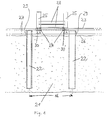
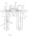
- FIG. 1 shows a vertical section through the device according to the invention.
- a non-reinforced mixed-in-place wall 21 are at a distance 16 support members 22 which protrude beyond the surface 26 of the mixed-in-place wall 21.
- a continuous head bar 23 made of concrete, which consists of a reinforcing cage 27 and are integrated in the connecting elements 24.
- columns 25 can be fastened non-positively to these connecting elements 24, between the dam beams 28 can be hung.
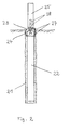
- Figure 2 shows a rotated by 90 ° to Figure 1 out, vertical section.
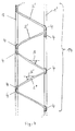
- FIGS. 3 to 5 show an embodiment variant according to the invention of mounting elements 14, from which the carrier elements 22 can be formed.
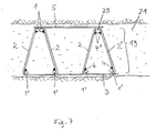
- Figures 6 to 8 show horizontal sections through the mixed-in-place wall 21, in which different trained support members 22 are set, which in turn consist of combinations of the mounting element 14.
- FIG. 9 shows a variant in which the mixed-in-place wall 21 essentially consists of individual slots 31 for the carrier elements 22.
- Suitable foundation measures for such flood protection walls would be winkeising walls, secant bored pile walls, concrete slot walls or continuous sheet piling. Temporary protective walls could be securely fastened to these foundation measures.
- the invention therefore describes an economical as well as safe system with which temporary flood protection walls can be erected.
- the attachment of the temporary flood protection walls takes place in such a way that initially as a foundation and sealing wall unweighted mixed-in-place wall 21 is produced by the mixed-in-place process.
- the soil in question is converted into a soil mortar by one or more rod-shaped agitators or slit-wall cutter-like devices in the soil.
- water, binder and possibly additives or bentonite is added via the stirring tools or milling and mixed in this way the pending soil to a soil mortar.
- These support elements 22 are designed so that they can absorb vertical forces, horizontal forces and bending moments and can dissipate via the mixed-in-place wall 21 in the ground.
- carrier elements 22 it is preferred to use rolled carriers such as IPB carriers, double U carriers, tubes, sheet piles, bars, plates or combinations of these agents.
- prefabricated concrete columns or precast concrete piles are introduced into the slot filled with floor mortar, which have a free connection reinforcement on the air side.
- a particular variant of the invention is that for the support elements 22 mounting elements 14 and combinations of these mounting elements 14 are used ( Figure 3 to Figure 8).
- Such mounting elements 14 are particularly inexpensive compared to rolling beams and complicated welding devices.
- the elements 14 consist of substantially mutually parallel longitudinal bars 1, 1 ', 1 "..., which are non-positively connected by zig-zag or wavy arranged diagonal bars 2.
- a steel bar may be formed zigzag or wavy over a longer range ( Figure 3) or single diagonal bars 2 'or individual substantially triangular curved bars 2 "are used ( Figures 4 and 5).
- Static requirements may require that the longitudinal bars be connected to each other on two sides or through several layers of diagonal bars (Figure 8).
- welds 4 are preferably arranged in the arcs or tips of the diagonal bars 2 and the dimensions of the diagonal bars 2 are chosen so that the Longitudinal bars 1, 1 '... are as far outside as possible in the wall and thus larger bending moments can be absorbed.
- the inclination angles ⁇ , ⁇ ', with which the diagonal bars 2 run towards the longitudinal bars, are preferably in the range between 30 ° and 60 °.
- the diagonal bars 2 between the longitudinal bars 1, 1 ' should be as straight as possible.
- FIG. 5 shows a variant embodiment in which elements 14 are arranged triangular in relation to one another on the left side. On the right side, two elements 14 are combined to form a triangular element 19, in which a longitudinal bar 20 and longitudinal bars 1 'are non-positively and statically operatively welded to one another via two or more diagonal bars by welds 4, 4'. It may be expedient that in this case the size of the cross-sectional area of the longitudinal bar 20 is different than the cross-sectional area of the longitudinal bars 1 '.
- the longitudinal bars 1, 1 '... and the diagonal bars 2 are preferably made of profiled or ribbed structural steels with circular cross sections. In principle, however, all cross-sectional shapes are conceivable.
- the embodiment of the elements 14 can be made both of smooth steels, but preferably of steels, which have a certain roughness by mechanical processing or coating, which causes higher adhesive stresses in the floor mortar.
- each element 14 Preferably, only one earth-side bar 1 and one air-side bar 1 'are arranged on each element 14, whose cross-sectional areas can also vary.
- the later-mounted flood protection walls are higher, it may be expedient to equip the elements 14 with a plurality of longitudinal bars 1, 1 ', 1 "for static reasons (FIG. 8).
- the diagonal bars can also be welded between the longitudinal bars (FIG. 5).
- the elements 14 are preferably installed vertically and aligned so that their larger expanse area comes to lie across the plane of the mixed-in-place wall.
- angles ⁇ and ⁇ 'of these surfaces to the wall normal are preferably in a range between -45 ° and + 45 °.
- At least two or more elements 14 are combined with one another at the locations of the concentrated introduction of force.
- the elements 14 are introduced into the freshly prepared mortar only after preparation of the mixed-in-place wall 21, which is done by pure impressions or slight vibration, the elements 14 by suitable binding plates 3, 3 ', 5 in their arrangement to each other be fixed.
- the elements 14 are connected by constructive welds or by binding wire with the binding plates.
- the binding plates can also be replaced by rods.
- the binding plates 3, 3 ', 5 are arranged at intervals of about 0.5 to 2 m.
- the dimensions of the elements 14 are chosen to have sufficient steel coverage through the floor mortar within the mixed-in-place wall 21. It lies in the centimeter range.
- a reinforcing cage 27 is arranged in the head region 29 of the support elements 22, which connects the individual heads of the support elements 22 so that after concreting the head beam 23 vertical forces, horizontal forces, bending moments and Torsionsmomente of these can be included.
- the heads 29 of the support members 22, the reinforcement 27 and the connecting members 24 are concreted into the concrete of the head beam 23, the head beam concrete being substantially waterproofed to the surface 26 of the MIP wall.
- the reinforcing cage 27 is formed in the formation of the longitudinal bars and brackets so that it can transmit forces that are introduced to the connecting elements 24, via torsion in the heads 29 of the support elements 22.
- the connecting elements 24 are preferably made of screws, threaded sleeves, Absteckbolzen, Absteckhülsen or from bayonet-like elements, which are directly or indirectly connected with tension or pressure anchoring elements according to the state of anchoring technology, as they are known from the reinforced concrete composite construction.
- Such anchoring elements 30 are z. B. expansion anchor, Flachfußanker, Plattenfußanker or steel elements with holes through which rebars are pulled.
- the transmission takes place essentially via torsional forces in the head beam.
- the support elements 22 in turn direct the forces into the unreinforced mixed-in-place wall 21 and from there they are removed into the ground.
- An elaborate fastening technique of the connecting elements 24 is the dimensionally accurate direct or indirect welding of the connecting elements 24 to the reinforcing bars 7 of the head bar or to the connection reinforcement 29 of the carrier elements 22.
- the connecting elements 24 are sunk into the head bar 23 so that they can be protected in flood-free times by cover plates.
- the columns 25 are fastened with screws, nuts or bayonet-type connecting means frictionally to the connecting elements 24.
- the surface of the head bar at least partially smooth, flat and horizontal form.
- the upper edge of the head beam is preferably arranged level with the terrain.
- the mixed-in-place wall 21 can be made as a continuous wall or consist of individual slots 31 which are located only in areas where the support members 22 are provided.
- the slots 31 extend into greater depths, so that the horizontal forces can be removed from the water pressure in the ground.
- the foundation device according to the invention for transportable, temporary flood protection walls is an economical, inexpensive and equivalent solution.
Abstract
Description
Die Erfindung beschreibt die Gründungsvorrichtung für einen transportablen und vorübergehenden Hochwasserschutz.The invention describes the foundation device for transportable and temporary flood protection.
In der Nähe von Flüssen und Seen besteht für die Anwohner in vielen Fällen die Gefahr von Hochwasserschäden.
Um diese zu vermeiden, gibt es unterschiedliche Schutzsysteme, welche kurzfristig errichtet werden können, um ein Eindringen des Wassers ins Hinterland zu verhindern.In the vicinity of rivers and lakes, residents often face the risk of flood damage.
To avoid this, there are different protection systems, which can be erected at short notice to prevent ingress of water into the hinterland.
So werden beispielsweise lange Schläuche mit Durchmesser von 1 m und mehr verlegt, welche mit Wasser aufgefüllt werden und auf diese Weise eine Wassersperre bilden.
Andere Konstruktionen bestehen darin, dass geneigte Platten oder Paletten, welche durch Stützen schräg abgestützt werden können, mit Folien überzogen werden und somit eine Abdichtung gegen das Hochwasser darstellen.For example, long tubes with a diameter of 1 m and more are laid, which are filled with water and thus form a water barrier.
Other constructions are that inclined plates or pallets, which can be supported by columns obliquely, are coated with films and thus provide a seal against the flood.
Bei diesen verhältnismäßig leichten Vorrichtungen besteht jedoch eine große Gefahr darin, dass Treibgut im Wasser zu gefährlichen Verletzungen dieser Schutzwälle führen kann.
Das bringt in der Regel einen plötzlichen Zusammenbruch des gesamten Systems mit sich.In these relatively light devices, however, there is a great danger that flotsam in the water can lead to dangerous injuries of these protective walls.
This usually involves a sudden collapse of the entire system.
Wenn bereits eine stabile Uferbefestigung vorhanden ist, gibt es sehr sichere Schutzmaßnahmen, bei denen an der Ufermauer nachträglich Säulen befestigt werden, deren Zwischenräume mit Dammbalken verschlossen werden.If there is already a stable bank fortification, there are very safe protective measures, in which columns are attached to the seawall, the interstices are closed with dam beams.
Fehlen solche Uferbefestigungen oder Ufermauern, so werden für die Erstellung solcher Schutzmaßnahmen teure Gründungsbauwerke notwendig.In the absence of such bank fortifications or embankment walls, expensive foundation structures are necessary for the creation of such protective measures.
Die Erfindung hat die Aufgabe, mit einfachen und preisgünstigen Gründungsmaßnahmen den wirtschaftlichen Einsatz von sicheren, transportablen Hochwasserschutzwänden zu ermöglichen.The object of the invention is to enable the economical use of safe, transportable flood protection walls with simple and inexpensive foundation measures.
Die Lösung erfolgt entsprechend den Merkmalen der Patentansprüche.The solution is carried out according to the features of the claims.
Die Erläuterung der Erfindung erfolgt anhand der Figuren.The explanation of the invention is based on the figures.
Figur 1 zeigt einen vertikalen Schnitt durch die erfindungsgemäße Vorrichtung. In einer unbewehrten Mixed-in-Place-Wand 21 befinden sich im Abstand 16 Trägerelemente 22, welche über die Oberfläche 26 der Mixed-in-Place-Wand 21 herausragen.FIG. 1 shows a vertical section through the device according to the invention. In a non-reinforced mixed-in-
Über der Mixed-in-Place-Wand 21 befindet sich ein durchgehender Kopfbalken 23 aus Beton, der aus einem Bewehrungskorb 27 besteht und in den Verbindungselemente 24 integriert sind.Above the mixed-in-
An diese Verbindungselemente 24 können im Falle eines Hochwassers Säulen 25 kraftschlüssig befestigt werden, zwischen die Dammbalken 28 eingehängt werden können.In the event of a flood,
Figur 2 zeigt einen um 90° verdreht zur Figur 1 geführten, vertikalen Schnitt.Figure 2 shows a rotated by 90 ° to Figure 1 out, vertical section.
Figur 3 bis 5 zeigen eine erfindungsgemäße Ausführungsvariante von Einbauelementen 14, aus denen die Trägerelemente 22 gebildet werden können.FIGS. 3 to 5 show an embodiment variant according to the invention of
Figur 6 bis 8 zeigen horizontale Schnitte durch die Mixed-in-Place-Wand 21, in denen unterschiedliche ausgebildete Trägerelemente 22 eingestellt sind, welche wiederum aus Kombinationen des Einbauelementes 14 bestehen.Figures 6 to 8 show horizontal sections through the mixed-in-
Figur 9 zeigt eine Ausführungsvariante, bei der die Mixed-in-Place-Wand 21 im Wesentlichen aus einzelnen Schlitzen 31 für die Trägerelemente 22 besteht.FIG. 9 shows a variant in which the mixed-in-
In vielen hochwassergefährdeten Gebieten, bei denen keine spezielle Hochwassersicherung oder kein besonderer Uferverbau vorhanden ist, wäre ein temporärer Hochwasserschutz mit einer Bauhöhe von ca. 1 - 2 m sehr wünschenswert.In many flood-prone areas, where there is no special flood protection or no special bank development, a temporary flood protection with a height of about 1 - 2 m would be very desirable.
Auf eine solche temporäre Hochwasserschutzwand wirken bei Hochwasser Kräfte von 10 - 20 kN/lfm Wandfläche, die aus dem Wasserdruck herrühren. Zudem sollten die Schutzwände mit einem Zuschlag für Lasten aus Treibgut bemessen werden.
Diese Belastung bewirkt erhebliche Druckkräfte und Biegemomente auf die Hochwasserschutzwand, welche wiederum durch besondere Gründungsmaßnahmen aufgenommen werden müssen.For such a temporary flood protection wall, at high tide, forces of 10 to 20 kN / m wall surface, which result from the water pressure, act. In addition, the protective walls should be dimensioned with a surcharge for loads from flotsam.
This load causes considerable pressure forces and bending moments on the flood protection wall, which in turn must be absorbed by special foundation measures.
Zusätzlich muss eine Unterspülung der transportablen Hochwasserschutzwände verhindert werden.In addition, a flushing of the transportable flood protection walls must be prevented.
Geeignete Gründungsmaßnahmen für solche Hochwasserschutzwände wären Winkeisiützmauern, überschnittene Bohrpfahlwände, Betonschlitzwände oder durchgehend eingebrachte Spundwände.
An diesen Gründungsmaßnahmen könnten temporäre Schutzwände sicher befestigt werden.Suitable foundation measures for such flood protection walls would be winkeising walls, secant bored pile walls, concrete slot walls or continuous sheet piling.
Temporary protective walls could be securely fastened to these foundation measures.
Dass man solche Gründungsmaßnahmen einfach einige Meter über das Gelände hochführt, ist in den meisten Fällen aus touristischen sowie aus Gründen des Landschaftsschutzes nicht wünschenswert und durchführbar.It is not desirable and practicable in most cases for reasons of tourism and landscape conservation to simply carry out such foundation measures a few meters above the ground.
Die beschriebenen Gründungsmaßnahmen erweisen sich zudem als sehr arbeitsaufwendig und teuer.The described foundation measures also prove to be very laborious and expensive.
Die Erfindung beschreibt deshalb ein sowohl wirtschaftliches als auch sicheres System, mit dem temporäre Hochwasserschutzwände errichtet werden können.The invention therefore describes an economical as well as safe system with which temporary flood protection walls can be erected.
Die Befestigung der temporären Hochwasserschutzwände erfolgt in der Weise, dass zunächst als Gründungs- und Abdichtungswand eine unbewehrte Mixed-in-Place-Wand 21 nach dem Mixed-in-Place-Verfahren hergestellt wird.
Beim Mixed-in-Place-Verfahren wird der anstehende Boden durch eine oder mehrere stangenförmige Rührwerkzeuge oder durch schlitzwandfräsenähnliche Vorrichtungen im Boden zu einem Bodenmörtel umgewandelt.
Dabei wird über die Rührwerkzeuge oder Fräsen Wasser, Bindemittel und ggf. Zusatzmittel oder Bentonit zugegeben und auf diese Weise der anstehende Boden zu einem Bodenmörtel vermischt.The attachment of the temporary flood protection walls takes place in such a way that initially as a foundation and sealing wall unweighted mixed-in-
In the mixed-in-place process, the soil in question is converted into a soil mortar by one or more rod-shaped agitators or slit-wall cutter-like devices in the soil.
In this case, water, binder and possibly additives or bentonite is added via the stirring tools or milling and mixed in this way the pending soil to a soil mortar.
Vorteil dieses Mixed-in-Place-Verfahrens ist unter anderem, dass man sich das Wegfahren des Aushubs sparen kann und des Weiteren ist der Bodenmörtel wesentlich preiswerter als der Beton, wie er in Schlitzwänden eingebaut wird.
Insbesondere in nichtbindigen Böden kann man durch Zugabe von geeigneten Bindemitteln die bevorzugterweise auf Zementbasis sind, beim Mixed-in-Place-Verfahren Druckfestigkeiten erreichen, die zwischen 5 und 15 N/mm2 liegen. Somit können solche Wände auch statisch belastet werden.One of the benefits of this mixed-in-place process is that you can save on driving away the excavation and, moreover, the floor mortar is much cheaper than the concrete installed in diaphragm walls.
Especially in non-cohesive soils, by adding suitable binders which are preferably cement based, in the mixed-in-place process, compressive strengths of between 5 and 15 N / mm 2 can be achieved . Thus, such walls can be loaded statically.
In den frischen Mörtel werden Trägerelemente 22 im Abstand 16 eingedrückt oder eingerüttelt.In the fresh
Diese Trägerelemente 22 sind so ausgebildet, dass sie vertikale Kräfte, horizontale Kräfte und Biegemomente aufnehmen können und über die Mixed-in-Place-Wand 21 in den Baugrund abtragen können.These
Als Trägerelemente 22 werden bevorzugterweise Walzträger wie IPB-Träger, Doppel-U-Träger, Rohre, Spundwände, Stäbe, Bleche oder Kombinationen aus diesen Mitteln verwendet.As
Ebenso sind für die Trägerelemente 22 Bewehrungskörbe mit rundem und eckigem Querschnitt denkbar, wie sie aus Bohrpfählen oder Schlitzwänden bekannt sind.Likewise, 22 reinforcement cages with round and square cross-section are conceivable for the support elements, as they are known from bored piles or diaphragm walls.
In einer weiteren erfindungsgemäßen Variante werden in den mit Bodenmörtel gefüllten Schlitz Fertigbetonsäulen oder Fertigbetonrammpfähle eingebracht, die an der Luftseite eine freie Anschlussbewehrung besitzen.In a further variant according to the invention, prefabricated concrete columns or precast concrete piles are introduced into the slot filled with floor mortar, which have a free connection reinforcement on the air side.
Eine besondere erfindungsgemäße Ausführungsvariante besteht darin, dass für die Trägerelemente 22 Einbauelemente 14 und Kombinationen aus diesen Einbauelementen 14 verwendet werden (Figur 3 bis Figur 8).A particular variant of the invention is that for the
Solche Einbauelemente 14 sind besonders preisgünstig gegenüber Walzträgern und komplizierten Schweißvorrichtungen.
Die Elemente 14 bestehen aus im Wesentlichen parallel zueinander liegenden Längsstäben 1, 1', 1" ..., welche durch zick-zack-förmige oder wellenförmig angeordnete Diagonalstäbe 2 kraftschlüssig miteinander verbunden sind.The
Für die Diagonalstäbe 2 kann ein Stahlstab über einen längeren Bereich zickzackförmig oder wellenförmig ausgebildet werden (Fig. 3) oder es werden einzelne Diagonalstäbe 2' oder einzelne im Wesentlichen dreiecksförmige gebogene Stäbe 2" verwendet (Fig. 4 und 5).For the
Statische Erfordernisse können es notwendig machen, dass die Längsstäbe zu beiden Seiten oder durch mehrere Lagen Diagonalstäbe miteinander verbunden werden (Fig. 8).Static requirements may require that the longitudinal bars be connected to each other on two sides or through several layers of diagonal bars (Figure 8).
Diese Verbindung erfolgt über statisch wirksame und bemessene Schweißnähte 4.This connection is made by statically effective and measured welds. 4
Diese Schweißnähte 4 werden bevorzugterweise in den Bögen oder Spitzen der Diagonalstäbe 2 angeordnet und die Dimensionen der Diagonalstäbe 2 sind so gewählt, dass die Längsstäbe 1, 1'... möglichst weit außen in der Wand liegen und somit größsere Biegemomente aufgenommen werden können.These
Die Neigungswinkel β, β', mit denen die Diagonalstäbe 2 auf die Längseisen zulaufen, liegen bevorzugterweise in Bereichen zwischen 30° und 60°.The inclination angles β, β ', with which the
Aus Gründen des Kräfteflusses sollten dabei die Diagonalstäbe 2 zwischen den Längsstäben 1, 1'... möglichst geradlinig verlaufen.For reasons of force flow, the
Figur 5 zeigt eine Ausführungsvariante, in der auf der linken Seite Elemente 14 dreiecksförmig zueinander angeordnet sind.
Auf der rechten Seite sind 2 Elemente 14 zu einem dreieckigen Element 19 zusammengefasst, bei dem ein Längsstab 20 und Längsstäbe 1' über zwei oder mehrere Diagonalstäbe durch Schweißnähte 4, 4' kraftschlüssig und statisch wirksam miteinander verschweißt sind. Es kann zweckmäßig sein, dass in diesem Fall die Größe der Querschnittsfläche des Längsstabes 20 anders ist als die Querschnittsfläche der Längsstäbe 1'.FIG. 5 shows a variant embodiment in which
On the right side, two
Die Längsstäbe 1, 1' ... und die Diagonalstäbe 2 bestehen bevorzugterweise aus profilierten oder gerippten Baustählen mit kreisförmigen Querschnitten. Prinzipiell sind jedoch alle Querschnittsformen denkbar.The
Die Ausführung der Elemente 14 kann sowohl aus glatten Stählen erfolgen, bevorzugt jedoch aus Stählen, die durch mechanische Bearbeitung oder Beschichtung eine gewisse Rauhigkeit aufweisen, was höhere Haftspannungen im Bodenmörtel bewirkt.The embodiment of the
Zur Erhöhung der Nutzungsdauer der Verbauwand kann es sinnvoll sein, die Elemente 14 mit Korrosionsschutzbeschichtungen zu versehen.To increase the service life of the shoring wall, it may be useful to provide the
Bevorzugterweise werden an jedem Element 14 nur ein erdseitiger Stab 1 und ein luftseitiger Stab 1' angeordnet, deren Querschnittsflächen auch variieren können.Preferably, only one earth-
Werden die später aufgesetzten Hochwasserschutzwände höher, kann es zweckmäßig sein, die Elemente 14 aus statischen Gründen mit mehreren Längsstäben 1, 1', 1"... auszustatten (Fig. 8).If the later-mounted flood protection walls are higher, it may be expedient to equip the
Die Längsstäbe 1, 1' können auf der gleichen Seite der zick-zack- oder wellenförmigen angeordneten Diagonalstäbe 2 liegen oder auf unterschiedlichen Seiten. Diese Variante ist auf der rechten Seite der Figur 8 dargestellt.The
Ebenso können die Diagonalstäbe auch zwischen den Längsstäben eingeschweißt werden (Fig. 5).Likewise, the diagonal bars can also be welded between the longitudinal bars (FIG. 5).
Die Elemente 14 werden bevorzugterweise lotrecht und so ausgerichtet eingebaut, dass ihre größere Ausdehnungsfläche quer zur Ebene der Mixed-in-Place-Wand zum Liegen kommt.The
Die Winkel α und α' dieser Flächen zur Wandnormalen liegen bevorzugterweise in einem Bereich zwischen -45° und +45°.The angles α and α 'of these surfaces to the wall normal are preferably in a range between -45 ° and + 45 °.
Zum optimalen Kräftefluss werden an den Orten der konzentrierten Krafteinleitung mindestens zwei oder mehr Elemente 14 miteinander kombiniert.For optimum flow of force, at least two or
Da die Elemente 14 erst nach Herstellung der Mixed-in-Place-Wand 21 in den frisch hergestellten Mörtel eingebracht werden, was durch reines Eindrücken oder leichtes Einvibrieren erfolgt, müssen die Elemente 14 durch geeignete Bindebleche 3, 3', 5 in ihrer Anordnung zueinander fixiert werden.Since the
Dabei werden die Elemente 14 durch konstruktive Schweißnähte oder durch Bindedraht mit den Bindeblechen verbunden.The
Die Bindebleche können dabei auch durch Stäbe ersetzt werden.The binding plates can also be replaced by rods.
Bevorzugterweise werden die Bindebleche 3, 3', 5 in Abständen von ca. 0,5 - 2 m angeordnet.Preferably, the binding
Die Abmessungen der Elemente 14 werden so gewählt, dass sie innerhalb der Mixed-in-Place-Wand 21 eine ausreichende Stahlüberdeckung durch den Bodenmörtel besitzen. Sie liegt im Zentimeterbereich.The dimensions of the
Die richtige Lage der Kombination mehrerer Elemente 14 in der Mixed-in-Place-Wand kann durch zusätzliche Abstandhalter erfolgen, die in den Zeichnungen nicht extra dargestellt sind.The correct location of the combination of
Nach dem Abbinden des Bodenmörtels in der unbewehrten Mixed-in-Place-Wand 21 wird im Kopfbereich 29 der Trägerelemente 22 ein Bewehrungskorb 27 angeordnet, welcher die einzelnen Köpfe der Tragelemente 22 so verbindet, dass nach dem Betonieren des Kopfbalkens 23 Vertikalkräfte, Horizontalkräfte, Biegemomente und Torsionsmomente von diesen aufgenommen werden können.After setting the soil mortar in the unreinforced mixed-in-
In diesen Bewehrungskorb 27 binden Verankerungselemente 30 ein, die wiederum an Verbindungselementen 24 befestigt sind.Anchoring
Die Köpfe 29 der Trägerelemente 22, die Bewehrung 27 und die Verbindungselemente 24 werden in den Beton des Kopfbalkens 23 einbetoniert, wobei der Kopfbalkenbeton im Wesentlichen wasserdicht an die Oberfläche 26 der MIP-Wand anbetoniert ist.The
Der Bewehrungskorb 27 ist in der Ausbildung der Längseisen und Bügel so ausgebildet, dass er Kräfte, die an den Verbindungselementen 24 eingeleitet werden, über Torsion in die Köpfe 29 der Trägerelemente 22 weiterleiten kann.The reinforcing
Die Verbindungselemente 24 bestehen bevorzugt aus Schrauben, Gewindemuffen, Absteckbolzen, Absteckhülsen oder aus bajonettschlussartigen Elementen, welche direkt oder indirekt mit Zug- oder Druckverankerungselementen nach dem Stand der Verankerungstechnik verbunden sind, wie sie aus dem Stahlbeton-Verbundbau bekannt sind.The connecting
Solche Verankerungselemente 30 sind z. B. Spreizanker, Flachfußanker, Plattenfußanker oder Stahlelemente mit Löchern, durch welche Bewehrungseisen gezogen werden.
Mit diesen gewellten Verbindungsmitteln und Verankerungsmitteln ist es möglich, die Lasten aus Wasserdruck, welche über die Dammbalken 28 in die Säulen 25 wirken, über den Kopfbalken 23 in die Köpfe der Trägerelemente 22 einzuleiten.With these corrugated connection means and anchoring means, it is possible to initiate the loads of water pressure, which act on the dam bars 28 in the
Die Übertragung erfolgt dabei im Wesentlichen über Torsionskräfte im Kopfbalken.The transmission takes place essentially via torsional forces in the head beam.
Die Trägerelemente 22 leiten wiederum die Kräfte in die unbewehrte Mixed-in-Place-Wand 21 und von dort aus werden sie ins Erdreich abgetragen.The
Eine wenn auch aufwendige Befestigungstechnik der Verbindüngselemente 24 ist das maßgenaue direkte oder indirekte Anschweißen der Verbindungselemente 24 an die Bewehrungseisen 7 des Kopfbalkens oder an die Anschlussbewehrung 29 der Trägerelemente 22.An elaborate fastening technique of the connecting
In einer bevorzugten Ausführungsart werden die Verbindungselemente 24 in den Kopfbalken 23 so versenkt eingebaut, dass sie in hochwasserfreien Zeiten durch Abdeckplatten geschützt werden können.In a preferred embodiment, the connecting
Die Säulen 25 werden mit Schrauben, Muttern oder bajonettartigen Verbindungsmitteln kraftschlüssig an den Verbindungselementen 24 befestigt.The
Da die horizontalen Abstände der später zu montierenden Säulen 25 wegen der einzusetzenden Dammbalken 28 auf wenige Zentimeter genau sein müssen, kann es zweckmäßig sein, die Verbindungselemente 24 und ggf. die daran befestigten Verankerungselemente 30 erst später in den Kopfbalken einzufügen.Since the horizontal distances of the
In diesem Fall werden im Kopfbalken beim Betonieren Aussparungen angeordnet, in welchen dann später die Verbindungselemente 24 mit höchster Genauigkeit eingebaut werden können. Der Kraftschluss erfolgt dann über hochfeste Vergussmörtel.In this case, recesses are arranged in the head bar during concreting, in which then later, the connecting
Um später eine dichte Verbindung zwischen dem untersten Dammbalken und der Betonoberfläche des Kopfbalkens 23 zu erreichen, ist es empfehlenswert, die Oberfläche des Kopfbalkens wenigstens teilweise glatt, eben und horizontal auszubilden.In order later to achieve a tight connection between the lowest dam bar and the concrete surface of the
Damit die Gründung für den Hochwasserschutz möglichst unauffällig ist und kein Hindernis für Fußgänger darstellt, wird die Oberkante des Kopfbalkens bevorzugt höhengleich mit dem Gelände angeordnet.So that the foundation for flood protection is as inconspicuous as possible and does not pose a hindrance to pedestrians, the upper edge of the head beam is preferably arranged level with the terrain.
Die Mixed-in-Place-Wand 21 kann als eine flächig durchgehende Wand hergestellt werden oder aus einzelnen Schlitzen 31 bestehen, welche nur in Bereichen angeordnet werden, wo die Trägerelemente 22 vorgesehen sind. Hier reichen die Schlitze 31 in größere Tiefen, damit die Horizontalkräfte aus dem Wasserdruck ins Erdreich abgetragen werden können.The mixed-in-
Zwischen diesen tiefen Schlitzen ist entweder keine oder eine weniger tiefe Mixed-in-Place-Wand angeordnet. Dies ist davon abhängig, wie groß die Gefahr der Unterspülung des Kopfbalkens 23 ist und dies ist im Wesentlichen von den Eigenschaften des anstehenden Bodens bedingt.Between these deep slots there is either no or a less deep mixed-in-place wall. This depends on how great the risk of undercutting the
Gegenüber Gründungen mit Bohrpfahlwänden, Schlitzwänden, Spundwänden oder Uferschutzmauern, stellt die erfindungsgemäße Gründungsvorrichtung für transportable, temporäre Hochwasserschutzwände eine wirtschaftliche, preiswerte und gleichwertige Lösung dar.Compared with foundations with bored pile walls, slot walls, sheet piling or bank protection walls, the foundation device according to the invention for transportable, temporary flood protection walls is an economical, inexpensive and equivalent solution.
Claims (15)
dass eine unbewehrte Mixed-in-Place-Wand (21) hergestellt wird, wobei der anstehende Boden an Ort und Stelle beispielsweise mittels stangenförmiger Rührwerkzeuge oder durch Fräsen unter Zugabe von Bindemitteln zu einem selbsterhärtendem Bodenmörtel gemischt wird
und dass in diese Mixed-in-Place-Wand (21) Trägerelemente (22) eingestellt werden, welche um einen Betrag (29) aus der Mixed-in-Place-Wand (21) herausragen
und dass auf die Mixed-in-Place-Wand (21) ein bewehrter Kopfbalken (23) aus Beton angeformt wird, welcher die überstehenden Trägerelemente (22) einschließt
und dass im Kopfbalken (23) lösbare Verbindungselemente (24) integriert sind, an welche Säulen (25) lösbar und kraftschlüssig befestigt werden können
und dass über den Kopfbalken (23) Biegemomente, Horizontalkräfte, Vertikalkräfte und Torsionsmomente in die Trägerelemente (22) übertragen werden.Foundation device for transportable, temporary flood protection characterized in that
that an unreinforced mixed-in-place wall (21) is produced, wherein the pending soil is mixed in situ, for example by means of rod-shaped stirring tools or by milling with the addition of binders to a self-hardening floor mortar
and that in this mixed-in-place wall (21) support elements (22) are set, which protrude by an amount (29) from the mixed-in-place wall (21)
and that on the mixed-in-place wall (21) a reinforced concrete head beam (23) is formed, which encloses the projecting support elements (22)
and that in the head bar (23) releasable connecting elements (24) are integrated, to which columns (25) can be releasably and non-positively attached
and that over the head bar (23) bending moments, horizontal forces, vertical forces and torsional moments in the support elements (22) are transmitted.
dass die Verbindungselemente (24) über Verankerungselemente (30), wie z. B. Spreizanker, Flachfußanker, Plattenfußanker oder Stahlelemente mit Löchern und durchgeführten Bewehrungseisen, oder sonstigen Elementen nach dem Stand der Verankerungstechnik, die Kräfte aus den Säulen (25) in den Kopfbalken (23) oder in die Köpfe (29) der Trägerelemente (22) eintragen.Device according to claim 1, characterized
that the connecting elements (24) via anchoring elements (30), such. As expansion anchors, Flachfußanker, Plattenfußanker or steel elements with holes and carried rebar, or other elements according to the state of anchoring technology, the forces from the columns (25) in the head beam (23) or in the heads (29) of the support elements (22) enter.
dass die Verbindungselemente (24) direkt oder über Zwischenelemente an die Bewehrungseisen (27) des Kopfbalkens (23) oder an die Köpfe (29) der Trägerelemente (22) angeschweißt sind.Device according to one of claims 1 to 2, characterized
that the connecting elements (24) are welded directly or via intermediate elements to the rebars (27) of the head bar (23) or on the heads (29) of the support elements (22).
dass die Verbindungselemente (24) im Wesentlichen aus Schrauben, Gewindemuffen, Absteckbolzen, Absteckhülsen oder Bajonettverschlüssen bestehen.Device according to one of claims 1 to 3, characterized
that the connecting elements (24) consist essentially of screws, threaded sleeves, Absteckbolzen, Absteckhülsen or bayonet locks.
dass die Trägerelemente (22) aus Walzprofilen, IPB-Trägern, Doppel-U-Trägern, Spundwänden, Rohren, Stäben, Blechen oder aus Kombinationen aus diesen Mitteln bestehen.Device according to one of claims 1 to 4, characterized
in that the carrier elements (22) consist of rolled profiles, IPB supports, double U-beams, sheet piling, pipes, rods, sheets or combinations of these means.
dass die Trägerelemente (22) Fertigbetonsäulen oder Fertigbetonrammpfähle sind, welche an der Luftseite (29) eine Anschlussbewehrung oder Mittel zur Befestigung einer Anschlussbewehrung haben.Device according to claim 1, characterized
in that the carrier elements (22) are precast concrete columns or precast concrete piles which have a connection reinforcement on the air side (29) or means for fastening a connection reinforcement.
dass die Trägerelemente (22) im Wesentlichen Bewehrungskörbe sind, wie sie für Bohrpfähle und Schlitzwände zur Anwendung kommen.Device according to claim 1, characterized
in that the carrier elements (22) are essentially reinforcing baskets used for bored piles and diaphragm walls.
dass die Trägerelemente (22) aus Einbauelementen (14) bestehen, welche im Wesentlichen aus senkrecht verlaufenden Längsstäben (1, 1', 1" ...) bestehen, welche mit zackenförmigen oder gewellt angeordneten Diagonalstäben (2, 2', 2") durch statisch wirksame Schweißnähte (4) kraftschlüssig miteinander verbunden sind
und dass mehrere Elemente (14) durch konstruktive Bindestäbe oder Bindebleche (3, 3', 5) in ihrer Anordnung zueinander fixiert werden
und dass sich die Längsstäbe (1, 1' ...) und die Diagonalstäbe (2) zumindest über einen Teil der Wandtiefe erstrecken.Device according to claim 1, characterized
in that the carrier elements (22) consist of built-in elements (14) which essentially consist of vertically extending longitudinal bars (1, 1 ', 1 "...) which are provided with serrated or undulating diagonal bars (2, 2', 2"). By statically effective welds (4) are non-positively connected to each other
and that a plurality of elements (14) by means of constructive binding rods or binding plates (3, 3 ', 5) are fixed in their arrangement to each other
and that the longitudinal bars (1, 1 '...) and the diagonal bars (2) extend over at least part of the wall depth.
dass die Elemente (14) unter Winkeln (α, α') zur Wandflächennormalen geneigt sind, die bevorzugterweise in einem Bereich von +45° bis -45° liegen.Device according to claim 8, characterized
that the elements (14) at angles (α, α ') are inclined to the wall surface normals, which is preferably be in a range of + 45 ° to -45 °.
dass die Längsstäbe (1, 1', 1", 1"' ...) auf der gleichen Seite oder auf unterschiedlichen Seiten der zackenförmig oder der wellenförmig angeordneten Diagonalstäbe (2) angeschweißt sind.Device according to one of claims 8 to 9, characterized
that the longitudinal rods (1, 1 ', 1 ", 1"', ...) are welded on the same side or on different sides of the serrated or wave-shaped arrangement of diagonal bars (2).
dass die Längsstäbe (1, 1', 1" ...) oder die Diagonalstäbe (2) aus glatten oder gerippten oder profilierten Stahlstäben bestehen.Device according to one of claims 8 to 10, characterized
that the longitudinal bars (1, 1 ', 1 "...) or the diagonal bars (2) consist of smooth or ribbed or profiled steel bars.
dass Längsstäbe (1,1',1") und Diagonalstäbe (2) eine Korrosionsschutzbeschichtung besitzen.Device according to claims 8 to 11, characterized
that the longitudinal bars (1,1 ', 1 ") and diagonal bars (2) have a corrosion protection coating.
dass die Diagonalstäbe (2) zwischen den Längsstäben (1,1',1") möglichst geradlinig ausgebildet sind und unter Winkeln (β, β') im bevorzugten Bereich zwischen ca. 30° und 60° zu den Längsstäben (1, 1' ...) geneigt sind.Device according to one of claims 8 to 12, characterized
that the diagonal bars (2) between the longitudinal bars (1,1 ', 1 ") are formed as straight as possible and at angles (β, β') in the preferred range between about 30 ° and 60 ° to the longitudinal bars (1, 1 ' ...) are inclined.
dass die konzentrierte Krafteinleitung durch Elemente (19) erfolgt, welche im horizontalen Schnitt eine im Wesentlichen dreiecksförmige Anordnung von erdseitigen (21) Längsstäben (20) und luftseitigen (10) Längsstäben (1') darstellen, wobei die kraftschlüssige Verbindung über mindestens zwei zackenförmig oder wellenförmig angeordnete Diagonalstäbe (2, 2', 2") und statisch wirkende Schweißnähte (4, 4') erfolgt.Device according to one of claims 8 to 13, characterized
in that the concentrated introduction of force is effected by elements (19) which in horizontal section represent a substantially triangular arrangement of earth-side (21) longitudinal bars (20) and air-side (10) longitudinal bars (1 '), wherein the non-positive connection via at least two serrated or Wavy arranged diagonal bars (2, 2 ', 2 ") and statically acting welds (4, 4') takes place.
dass die unbewehrte Schlitzwand 21 nach dem Mixed-in-Place-Verfahren nicht durchgehend ist, sondern aus Einzelschlitzen (31) besteht, in denen die Trägerelemente (22) angeordnet sind und dass zwischen den Einzelschlitzen (31) keine oder eine weniger tiefe Schlitzwand nach dem Mixed-in-Place-Verfahren ist.Device according to one of claims 1 to 14, characterized
that the unreinforced diaphragm wall 21 according to the mixed-in-place method not is continuous, but consists of individual slots (31) in which the support elements (22) are arranged and that between the individual slots (31) is no or a less deep slot wall according to the mixed-in-place method.
Applications Claiming Priority (1)
| Application Number | Priority Date | Filing Date | Title |
|---|---|---|---|
| DE200510013993 DE102005013993B3 (en) | 2005-03-26 | 2005-03-26 | Foundation for a flood protection |
Publications (2)
| Publication Number | Publication Date |
|---|---|
| EP1707685A2 true EP1707685A2 (en) | 2006-10-04 |
| EP1707685A3 EP1707685A3 (en) | 2007-10-17 |
Family
ID=36694999
Family Applications (1)
| Application Number | Title | Priority Date | Filing Date |
|---|---|---|---|
| EP06005787A Withdrawn EP1707685A3 (en) | 2005-03-26 | 2006-03-21 | Foundation for a high water barrier |
Country Status (2)
| Country | Link |
|---|---|
| EP (1) | EP1707685A3 (en) |
| DE (1) | DE102005013993B3 (en) |
Cited By (4)
| Publication number | Priority date | Publication date | Assignee | Title |
|---|---|---|---|---|
| DE102006057811A1 (en) * | 2006-12-06 | 2008-06-19 | Franki Grundbau Gmbh & Co.Kg | Method for building isolating walls especially for securing underground construction by inserting prefabricated concrete sections and sealing with a filler |
| DE102009021143A1 (en) * | 2009-05-13 | 2010-11-18 | Haus und Holzbau im Allgäu GmbH | Foundation basket, foundation and method for forming a foundation |
| CN110029625A (en) * | 2019-05-23 | 2019-07-19 | 中建科技(福州)有限公司 | Detachable easily memory-type flood protection device |
| CN110344373A (en) * | 2019-07-29 | 2019-10-18 | 中水淮河规划设计研究有限公司 | A kind of installation method of plug type rubber dam stainless steel antiwear lining plate |
Citations (4)
| Publication number | Priority date | Publication date | Assignee | Title |
|---|---|---|---|---|
| JPH06257169A (en) * | 1993-03-03 | 1994-09-13 | Kajima Corp | Small-scale basement |
| WO1997004177A1 (en) * | 1995-07-17 | 1997-02-06 | Sovran Jean Paul | River bank flood barrier |
| WO2000050358A1 (en) * | 1999-02-25 | 2000-08-31 | Menard Soltraitement | Concrete comprising an elastic substance and pile made of such a concrete |
| US6450733B1 (en) * | 1996-11-20 | 2002-09-17 | Hans-Joachim Krill | Mobile anti-flood protection device |
Family Cites Families (6)
| Publication number | Priority date | Publication date | Assignee | Title |
|---|---|---|---|---|
| DE19526396C2 (en) * | 1995-07-19 | 2000-11-02 | Dyckerhoff Ag | Construction pit shoring, process for its production and building material mix therefor |
| DE19949655A1 (en) * | 1998-10-15 | 2000-09-21 | Bilfinger Berger Bau | Concrete header beams for free-standing sheet pile retaining walls etc. is manufactured in one piece of long length by sliding shutter method |
| DE29823360U1 (en) * | 1998-12-22 | 1999-05-20 | Bauer Spezialtiefbau | Waterproof surface reinforcement in diaphragm walls, sealing walls and sealing walls made of mortar columns using the "mixed-in-place" method |
| DE20107337U1 (en) * | 2001-04-27 | 2001-06-28 | Burger Hans Joachim | Flood protection device |
| DE20203203U1 (en) * | 2002-02-28 | 2002-06-27 | Burger Hans Joachim | Transparent flood protection |
| DE10238646B3 (en) * | 2002-08-23 | 2004-04-01 | Bauer Spezialtiefbau Gmbh | Production of water-tight vertical walls used in the production of building foundations comprises forming secondary lamellae in the spaces between the primary lamellae, and forming homogenizing lamellae between the other lamellae |
-
2005
- 2005-03-26 DE DE200510013993 patent/DE102005013993B3/en not_active Expired - Fee Related
-
2006
- 2006-03-21 EP EP06005787A patent/EP1707685A3/en not_active Withdrawn
Patent Citations (4)
| Publication number | Priority date | Publication date | Assignee | Title |
|---|---|---|---|---|
| JPH06257169A (en) * | 1993-03-03 | 1994-09-13 | Kajima Corp | Small-scale basement |
| WO1997004177A1 (en) * | 1995-07-17 | 1997-02-06 | Sovran Jean Paul | River bank flood barrier |
| US6450733B1 (en) * | 1996-11-20 | 2002-09-17 | Hans-Joachim Krill | Mobile anti-flood protection device |
| WO2000050358A1 (en) * | 1999-02-25 | 2000-08-31 | Menard Soltraitement | Concrete comprising an elastic substance and pile made of such a concrete |
Cited By (5)
| Publication number | Priority date | Publication date | Assignee | Title |
|---|---|---|---|---|
| DE102006057811A1 (en) * | 2006-12-06 | 2008-06-19 | Franki Grundbau Gmbh & Co.Kg | Method for building isolating walls especially for securing underground construction by inserting prefabricated concrete sections and sealing with a filler |
| DE102009021143A1 (en) * | 2009-05-13 | 2010-11-18 | Haus und Holzbau im Allgäu GmbH | Foundation basket, foundation and method for forming a foundation |
| CN110029625A (en) * | 2019-05-23 | 2019-07-19 | 中建科技(福州)有限公司 | Detachable easily memory-type flood protection device |
| CN110344373A (en) * | 2019-07-29 | 2019-10-18 | 中水淮河规划设计研究有限公司 | A kind of installation method of plug type rubber dam stainless steel antiwear lining plate |
| CN110344373B (en) * | 2019-07-29 | 2024-02-20 | 中水淮河规划设计研究有限公司 | Installation method of stainless steel abrasion-resistant lining plate of plug type rubber dam |
Also Published As
| Publication number | Publication date |
|---|---|
| DE102005013993B3 (en) | 2006-11-16 |
| EP1707685A3 (en) | 2007-10-17 |
Similar Documents
| Publication | Publication Date | Title |
|---|---|---|
| DE2628618B2 (en) | Process for building a quay wall in the water and structural element for carrying out the process | |
| CH707671B1 (en) | Supporting masonry element and retaining wall made of supporting masonry elements. | |
| AT391506B (en) | DEVICE FOR EXHAUSTING HEAT IN THE GROUND FLOOR OR TO RECOVER HEAT FROM THE GROUND FLOOR | |
| DE102005013993B3 (en) | Foundation for a flood protection | |
| DE2917994C2 (en) | Process for the production of a construction pit sheeting or retaining wall made of reinforced concrete for terrain cuts | |
| DE102005048304A1 (en) | High water level protection unit has steel support built into ground and protective wall bands of aluminum that can be drawn out and fixed in position and lowered when the waters recede | |
| EP2803786B1 (en) | Assembly and repair device | |
| DE1634589B2 (en) | PILE GRATING MADE FROM CONCRETE PILES | |
| DE102005013994B4 (en) | Device for the concentrated introduction of force into unreinforced diaphragm walls in the ground | |
| CH711288B1 (en) | Water-permeable supporting structure, in particular for slope stabilization as well as for terracing and terracing. | |
| DE102005010495B4 (en) | Device, dam formed therefrom and method for producing a dam | |
| DE19547911C2 (en) | Sheet pile wall made with sheet piles with a strap | |
| EP1964978B1 (en) | Method for erecting a wharfage and wharfage | |
| EP0922810B1 (en) | Method of securing slopes | |
| DE10360267B4 (en) | Method for producing a combined sheet piling | |
| AT317092B (en) | Process for the production of a trough arranged in the ground below the groundwater level and for this purpose prefabricated reinforced concrete girders for their production | |
| DE711114C (en) | Process for the production of structures lying in the ground or in the open water in an open structure | |
| DE1634589C3 (en) | Pile grid made of concrete piles | |
| DE2942428A1 (en) | New or existing harbour wall reinforcement - has submerged pile wall built from elements and intervening drilled tubes | |
| DE4445707A1 (en) | Economical removal of same level traffic surfaces | |
| DE3002739A1 (en) | CONSTRUCTION CONSTRUCTED BY WATERPROOF CONSTRUCTIONS, IN PARTICULAR BASIN, e.g. LIQUID STORAGE POOLS, SWIMMING POOLS O.AE. | |
| AT390290B (en) | Method of producing a slope protective structure, and slope protective structure produced according to this method | |
| WO2020187785A1 (en) | Foundation for a tower structure and method for establishing a foundation for a tower structure | |
| DE4220746A1 (en) | Protection of banks and underwater embankments to a depth of approximately 100 m - involves laying of several wire netting strips of customary width to form netting mat. | |
| AT388008B (en) | Method of constructing a retaining dam for a river power plant, and retaining dam produced by the method |
Legal Events
| Date | Code | Title | Description |
|---|---|---|---|
| PUAI | Public reference made under article 153(3) epc to a published international application that has entered the european phase |
Free format text: ORIGINAL CODE: 0009012 |
|
| AK | Designated contracting states |
Kind code of ref document: A2 Designated state(s): AT BE BG CH CY CZ DE DK EE ES FI FR GB GR HU IE IS IT LI LT LU LV MC NL PL PT RO SE SI SK TR |
|
| AX | Request for extension of the european patent |
Extension state: AL BA HR MK YU |
|
| PUAL | Search report despatched |
Free format text: ORIGINAL CODE: 0009013 |
|
| AK | Designated contracting states |
Kind code of ref document: A3 Designated state(s): AT BE BG CH CY CZ DE DK EE ES FI FR GB GR HU IE IS IT LI LT LU LV MC NL PL PT RO SE SI SK TR |
|
| AX | Request for extension of the european patent |
Extension state: AL BA HR MK YU |
|
| RIC1 | Information provided on ipc code assigned before grant |
Ipc: E02B 3/10 20060101ALI20070910BHEP Ipc: E02D 5/18 20060101ALI20070910BHEP Ipc: E02D 3/12 20060101ALI20070910BHEP Ipc: E02D 27/12 20060101AFI20060802BHEP |
|
| AKX | Designation fees paid | ||
| STAA | Information on the status of an ep patent application or granted ep patent |
Free format text: STATUS: THE APPLICATION IS DEEMED TO BE WITHDRAWN |
|
| 18D | Application deemed to be withdrawn |
Effective date: 20080418 |
|
| REG | Reference to a national code |
Ref country code: DE Ref legal event code: 8566 |