EP1707292A2 - Machining fluid level detection device for wire cut electrical discharge machines - Google Patents
Machining fluid level detection device for wire cut electrical discharge machines Download PDFInfo
- Publication number
- EP1707292A2 EP1707292A2 EP06250964A EP06250964A EP1707292A2 EP 1707292 A2 EP1707292 A2 EP 1707292A2 EP 06250964 A EP06250964 A EP 06250964A EP 06250964 A EP06250964 A EP 06250964A EP 1707292 A2 EP1707292 A2 EP 1707292A2
- Authority
- EP
- European Patent Office
- Prior art keywords
- voltage
- machining fluid
- machining
- fluid level
- electrode
- Prior art date
- Legal status (The legal status is an assumption and is not a legal conclusion. Google has not performed a legal analysis and makes no representation as to the accuracy of the status listed.)
- Granted
Links
- 238000003754 machining Methods 0.000 title claims abstract description 112
- 239000012530 fluid Substances 0.000 title claims abstract description 73
- 238000001514 detection method Methods 0.000 title claims description 24
- 239000010802 sludge Substances 0.000 description 9
- 238000009760 electrical discharge machining Methods 0.000 description 5
- 230000007797 corrosion Effects 0.000 description 3
- 238000005260 corrosion Methods 0.000 description 3
- 238000009499 grossing Methods 0.000 description 3
- 230000000694 effects Effects 0.000 description 2
- XLYOFNOQVPJJNP-UHFFFAOYSA-N water Substances O XLYOFNOQVPJJNP-UHFFFAOYSA-N 0.000 description 2
- 239000004020 conductor Substances 0.000 description 1
- 239000011810 insulating material Substances 0.000 description 1
- 239000012212 insulator Substances 0.000 description 1
- 230000007257 malfunction Effects 0.000 description 1
- 239000002184 metal Substances 0.000 description 1
- 238000009763 wire-cut EDM Methods 0.000 description 1
Images
Classifications
-
- B—PERFORMING OPERATIONS; TRANSPORTING
- B23—MACHINE TOOLS; METAL-WORKING NOT OTHERWISE PROVIDED FOR
- B23H—WORKING OF METAL BY THE ACTION OF A HIGH CONCENTRATION OF ELECTRIC CURRENT ON A WORKPIECE USING AN ELECTRODE WHICH TAKES THE PLACE OF A TOOL; SUCH WORKING COMBINED WITH OTHER FORMS OF WORKING OF METAL
- B23H1/00—Electrical discharge machining, i.e. removing metal with a series of rapidly recurring electrical discharges between an electrode and a workpiece in the presence of a fluid dielectric
- B23H1/10—Supply or regeneration of working media
-
- B—PERFORMING OPERATIONS; TRANSPORTING
- B23—MACHINE TOOLS; METAL-WORKING NOT OTHERWISE PROVIDED FOR
- B23H—WORKING OF METAL BY THE ACTION OF A HIGH CONCENTRATION OF ELECTRIC CURRENT ON A WORKPIECE USING AN ELECTRODE WHICH TAKES THE PLACE OF A TOOL; SUCH WORKING COMBINED WITH OTHER FORMS OF WORKING OF METAL
- B23H7/00—Processes or apparatus applicable to both electrical discharge machining and electrochemical machining
- B23H7/36—Supply or regeneration of working media
Definitions
- the present invention relates to a machining fluid level detection device for wire cut electrical discharge machines.
- Many wire cut electrical discharge machines are designed to perform machining on a workpiece immersed in an electrically conductive water-based machining fluid stored in a machining tank.
- the machining fluid is supplied to the machining tank before electrical discharge machining starts.
- the machining fluid level must be kept at a predetermined height in the machining tank.
- a float switch is usually used to detect the machining fluid level.
- FIG. 2 schematically shows a conventional machining tank using a float switch to detect the machining fluid level.
- the machining tank 1 has a table 2 disposed therein for mounting a workpiece. Machining tank 1 stores machining fluid 3. A ground wire 4 is connected to table 2.
- a float 5 which is attached via a float holding metal plate 6 to an upper guide 8 guiding a wire electrode, detects when the machining fluid level reaches a predetermined height in machining tank 1.
- Reference numeral 7 denotes a signal wire and reference numeral 9 denotes a nozzle provided on the upper guide.
- machining fluid level rises in proportion to the quantity of machining fluid supplied.
- float 5 rises and a float switch inside the float operates and outputs through signal wire 7 a machining fluid level detection signal indicating that the machining fluid level has reached the predetermined height. This detection signal stops the supply of machining fluid.
- a known machining fluid level detection device employs two electrodes separated by a predetermined distance (refer to Japanese Patent Application Laid-Open No. S63-123636 ).
- a predetermined voltage is applied between two separated electrodes.
- both of these electrodes are immersed in machining fluid, current flows between them, so that the machining fluid level can be detected by deciding whether or not the value of the current has reached a certain threshold.
- machining fluid level detection methods using a float switch are unreliable because the float switch may malfunction due to sludge or the signal wire may be broken due to electrical corrosion by the machining fluid.
- the machining fluid level detection method described in the above Japanese Patent Application Laid-Open No. S63-123636 has problems as well.
- Some machining fluid used for electrical discharge machining has a high specific resistance of approximately 200,000 ⁇ /cm. To allow current to flow between two electrodes through such a machining fluid, the electrodes must be as close as possible to each other, or the dimensions of the electrodes must be increased to enlarge the facing areas.
- the electrodes are placed inside the machining tank, enlarged electrodes would limit the size of the workpiece, or might be hit and damaged by the workpiece. Accordingly, the electrodes must be kept to a reasonable size.and the distance between the electrodes must be reduced. In the embodiment described in the above patent document, the distance between the electrodes is 1 mm. Such a narrow space between the electrodes can lead to false detection due to current flowing between the electrodes through a droplet held therebetween by surface tension after the machining fluid is discharged from the machining tank and the machining fluid level is quite low.
- the sludge produced by electrical discharge machining stays in the machining tank and accumulates on both the electrodes and the insulators holding them. During long unattended operation, which is common in electrical discharge machining, sludge may accumulate between the electrodes to such an extent that the electrodes are electrically connected to each other. In such a case, current flows between the electrodes even after the machining fluid has been discharged from the machining tank and the machining fluid level is quite low, which may cause false detection.
- the present invention provides a machining fluid level detection device for wire cut electrical discharge machines.
- the machining fluid level detection device comprises a machining tank storing a machining fluid with a table disposed therein for mounting a workpiece, means for connecting the machining tank and/or table to ground, an electrode for detecting the machining fluid level, a voltage application unit for applying a voltage between said electrode and the grounded machining tank and/or table, and a voltage comparing unit comparing the voltage between the electrode and the grounded machining tank and/or table with a predetermined threshold value to determine whether the machining fluid level has reached a predetermined height or not.
- the electrode may be attached insulated to the machining tank or an upper guide of the wire cut electrical discharge machine.
- the voltage application unit may comprise a DC constant current source, or a DC constant voltage source connected in series with a resistor.
- the voltage application unit may comprise an AC constant current source, or an AC constant voltage source connected in series with a resistor, and may be provided with a voltage measuring unit that rectifies the voltage between the electrode and the grounded machining tank and/or table and outputs the rectified voltage to the voltage comparing unit.
- the threshold value set in the voltage comparing unit may be variable.
- the table and/or machining tank is used as an electrode which faces the electrode attached via an insulating plate to the upper guide, so that there are no moving parts in the machining fluid level detecting means that come into direct contact with the machining fluid. Consequently, sludge does not affect the machining fluid level detecting means and does not clog the gap between the electrodes, either. Further, the signal wire and other parts are not damaged due to electric corrosion by the machining fluid. Thus, the machining fluid level can be detected reliably without the undesired effects of sludge in the machining fluid.
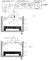
- FIG. 1 schematically shows a machining fluid level detection device for wire cut electrical discharge machining according to an embodiment of the present invention.
- elements identical to elements in the conventional device shown in FIG. 2 are indicated by the same reference numerals.
- a machining tank 1 has a table 2 disposed therein for mounting a workpiece.
- the table 2 is grounded through a ground wire 4.
- An electrode 10 is attached via an insulating plate 11 to an upper guide 8 guiding a wire electrode.
- a signal wire 7 is connected to electrode 10.
- the upper guide 8 is provided with a nozzle 9.
- the signal wire 7 is connected to a voltage application unit 20.
- the voltage application unit 20 comprises an AC constant current source.
- a voltage measuring unit 30 is connected to the signal wire 7 between the voltage application unit 20 and the electrode 10.
- a voltage comparing unit 40 is connected to the voltage measuring unit 30.
- the voltage measuring unit 30 comprises a buffer 31 connected to the signal wire 7, a full-wave rectifier circuit 32 rectifying the voltage output of a buffer 31, and a smoothing circuit 33 smoothing the full-wave rectified voltage.
- the output of the smoothing circuit 33 is inputted to the voltage comparing unit 40.
- the voltage comparing unit 40 which comprises a comparator 41, compares the output of the voltage measuring unit 30 with a preset threshold value. When the voltage outputted from the voltage measuring unit 30 drops below the threshold value, the voltage comparing unit 40 outputs a machining fluid level detection signal to a controller controlling the wire cut electrical discharge machine.
- a water-based electrically conductive machining fluid 3 is supplied to the machining tank 1.
- voltage measuring unit 30 This voltage value is inputted from voltage measuring unit 30 to voltage comparing unit 40 and compared with the predetermined threshold value to determine that the level of machining fluid 3 has not reached the predetermined height.
- FIG. 1 shows that the current from voltage application unit 20 flows in one direction, the current is actually AC, so that current flows in both directions.
- the resistance between electrode 10 and ground drops, even if the machining fluid has a high specific resistance of approximately 200,000 ⁇ /cm, and the voltage being inputted to the voltage measuring unit 30 drops to approximately 0 V.
- This voltage value is inputted from the voltage measuring unit 30 to the voltage comparing unit 40 and compared with the predetermined threshold value. If the input voltage is equal to or less than the threshold value, voltage comparing unit 40 outputs a signal indicating that machining fluid 3 has reached the predetermined height to a controller.
- machining tank 1 may be grounded instead if machining tank 1 is made of an electrically conductive material.
- both the table 2 and the machining tank 1 may be grounded.
- the voltage application unit 20 comprises an AC constant current source supplying a predetermined current
- it may comprise instead an AC constant voltage source connected in series with a resistor so that a predetermined current flows between electrode 10 and ground through the machining fluid and the table (and/or machining tank).
- machining fluid is supplied to the machining tank 1 with a workpiece mounted on the table, current also flows through the workpiece.
- the voltage application unit 20 may comprise a DC constant current source, or a DC constant voltage source connected in series with a resistor.
- the voltage measuring unit 30 may be omitted and the signal wire 7 may be connected directly to the input terminal of the voltage comparing unit 40 so that the voltage is inputted directly to the comparator 41 in the voltage comparing unit 40, or the voltage measuring unit 30 may be composed of buffer 31 only.
- the threshold value set in the comparator 41 of the voltage comparing unit 40 may be variable so that an appropriate threshold value can be set according to the type of machining fluid 3.
- the electrode 10 is attached via the insulating plate 11 to the upper guide 8 in the above embodiment, the electrode 10 may be attached via the insulating material to the machining tank 1.
- the machining fluid level detecting means since the table 2 or the machining tank 1 is used as the electrode facing the electrode 10 attached via the insulating plate 11 to the upper guide 8, the machining fluid level detecting means has no moving parts and can avoid the undesired effects of sludge in machining fluid 3, such as clogging of the inter-electrode gap.
Landscapes
- Engineering & Computer Science (AREA)
- Mechanical Engineering (AREA)
- Chemical & Material Sciences (AREA)
- Chemical Kinetics & Catalysis (AREA)
- Electrochemistry (AREA)
- Electrical Discharge Machining, Electrochemical Machining, And Combined Machining (AREA)
Abstract
Description
- The present invention relates to a machining fluid level detection device for wire cut electrical discharge machines.
- Many wire cut electrical discharge machines are designed to perform machining on a workpiece immersed in an electrically conductive water-based machining fluid stored in a machining tank. The machining fluid is supplied to the machining tank before electrical discharge machining starts. The machining fluid level must be kept at a predetermined height in the machining tank. A float switch is usually used to detect the machining fluid level.
- FIG. 2 schematically shows a conventional machining tank using a float switch to detect the machining fluid level. Referring to FIG. 2, the
machining tank 1 has a table 2 disposed therein for mounting a workpiece.Machining tank 1stores machining fluid 3. Aground wire 4 is connected to table 2. - A float 5, which is attached via a float holding metal plate 6 to an
upper guide 8 guiding a wire electrode, detects when the machining fluid level reaches a predetermined height inmachining tank 1.Reference numeral 7 denotes a signal wire andreference numeral 9 denotes a nozzle provided on the upper guide. - As machining fluid is supplied in the
machining tank 1, the machining fluid level rises in proportion to the quantity of machining fluid supplied. When the machining fluid level reaches the predetermined height, float 5 rises and a float switch inside the float operates and outputs through signal wire 7 a machining fluid level detection signal indicating that the machining fluid level has reached the predetermined height. This detection signal stops the supply of machining fluid. - In the machining tank, however, there remains sludge produced by electrical discharge machining. A large amount of sludge accumulates, especially after continuous rough machining. The sludge adheres to moving parts in the float switch and may prevent their operation. In addition, for structural reasons, the signal wire of the float switch is also immersed in the machining fluid, so the signal wire is eventually broken due to electric corrosion by the machining fluid.
- To solve the first problem, a known machining fluid level detection device employs two electrodes separated by a predetermined distance (refer to
Japanese Patent Application Laid-Open No. S63-123636 - As described above, conventional machining fluid level detection methods using a float switch are unreliable because the float switch may malfunction due to sludge or the signal wire may be broken due to electrical corrosion by the machining fluid. The machining fluid level detection method described in the above
Japanese Patent Application Laid-Open No. S63-123636 - Because the electrodes are placed inside the machining tank, enlarged electrodes would limit the size of the workpiece, or might be hit and damaged by the workpiece. Accordingly, the electrodes must be kept to a reasonable size.and the distance between the electrodes must be reduced. In the embodiment described in the above patent document, the distance between the electrodes is 1 mm. Such a narrow space between the electrodes can lead to false detection due to current flowing between the electrodes through a droplet held therebetween by surface tension after the machining fluid is discharged from the machining tank and the machining fluid level is quite low.
- The sludge produced by electrical discharge machining stays in the machining tank and accumulates on both the electrodes and the insulators holding them. During long unattended operation, which is common in electrical discharge machining, sludge may accumulate between the electrodes to such an extent that the electrodes are electrically connected to each other. In such a case, current flows between the electrodes even after the machining fluid has been discharged from the machining tank and the machining fluid level is quite low, which may cause false detection.
- The present invention provides a machining fluid level detection device for wire cut electrical discharge machines. The machining fluid level detection device comprises a machining tank storing a machining fluid with a table disposed therein for mounting a workpiece, means for connecting the machining tank and/or table to ground, an electrode for detecting the machining fluid level, a voltage application unit for applying a voltage between said electrode and the grounded machining tank and/or table, and a voltage comparing unit comparing the voltage between the electrode and the grounded machining tank and/or table with a predetermined threshold value to determine whether the machining fluid level has reached a predetermined height or not.
- The electrode may be attached insulated to the machining tank or an upper guide of the wire cut electrical discharge machine.
- The voltage application unit may comprise a DC constant current source, or a DC constant voltage source connected in series with a resistor. Alternatively, the voltage application unit may comprise an AC constant current source, or an AC constant voltage source connected in series with a resistor, and may be provided with a voltage measuring unit that rectifies the voltage between the electrode and the grounded machining tank and/or table and outputs the rectified voltage to the voltage comparing unit. The threshold value set in the voltage comparing unit may be variable.
- According to the present invention, the table and/or machining tank is used as an electrode which faces the electrode attached via an insulating plate to the upper guide, so that there are no moving parts in the machining fluid level detecting means that come into direct contact with the machining fluid. Consequently, sludge does not affect the machining fluid level detecting means and does not clog the gap between the electrodes, either. Further, the signal wire and other parts are not damaged due to electric corrosion by the machining fluid. Thus, the machining fluid level can be detected reliably without the undesired effects of sludge in the machining fluid.
-
- FIG. 1 schematically shows an embodiment of a machining fluid level detection device for a wire cut electrical discharge machine according to the present invention.
- FIG. 2 schematically shows a conventional machining fluid level detection device using a float switch.
- FIG. 1 schematically shows a machining fluid level detection device for wire cut electrical discharge machining according to an embodiment of the present invention. In this figure, elements identical to elements in the conventional device shown in FIG. 2 are indicated by the same reference numerals.
- A
machining tank 1 has a table 2 disposed therein for mounting a workpiece. The table 2 is grounded through aground wire 4. Anelectrode 10 is attached via an insulating plate 11 to anupper guide 8 guiding a wire electrode. Asignal wire 7 is connected toelectrode 10. Theupper guide 8 is provided with anozzle 9. - The
signal wire 7 is connected to avoltage application unit 20. In this embodiment, thevoltage application unit 20 comprises an AC constant current source. Avoltage measuring unit 30 is connected to thesignal wire 7 between thevoltage application unit 20 and theelectrode 10. Avoltage comparing unit 40 is connected to thevoltage measuring unit 30. Thevoltage measuring unit 30 comprises a buffer 31 connected to thesignal wire 7, a full-wave rectifier circuit 32 rectifying the voltage output of a buffer 31, and a smoothing circuit 33 smoothing the full-wave rectified voltage. The output of the smoothing circuit 33 is inputted to thevoltage comparing unit 40. Thevoltage comparing unit 40, which comprises a comparator 41, compares the output of thevoltage measuring unit 30 with a preset threshold value. When the voltage outputted from thevoltage measuring unit 30 drops below the threshold value, thevoltage comparing unit 40 outputs a machining fluid level detection signal to a controller controlling the wire cut electrical discharge machine. - With a voltage from the
voltage application unit 20 applied between theelectrode 10 and ground, a water-based electricallyconductive machining fluid 3 is supplied to themachining tank 1. Whenelectrode 10 is not immersed in the machining fluid, no current flows between theelectrode 10 and ground and therefore the maximum voltage generated by thevoltage application unit 20 is inputted tovoltage measuring unit 30. This voltage value is inputted fromvoltage measuring unit 30 tovoltage comparing unit 40 and compared with the predetermined threshold value to determine that the level ofmachining fluid 3 has not reached the predetermined height. - When the machining fluid level rises in the
machining tank 1 with additional supply ofmachining fluid 3 and reaches the predetermined position, theelectrode 10 is immersed in machiningfluid 3 and current flows between theelectrode 10 and ground, with the result that the voltage being inputted to thevoltage measuring unit 30 drops accordingly. Note that, although FIG. 1 shows that the current fromvoltage application unit 20 flows in one direction, the current is actually AC, so that current flows in both directions. - When
electrode 10 is fully immersed in machiningfluid 3, the resistance betweenelectrode 10 and ground drops, even if the machining fluid has a high specific resistance of approximately 200,000 Ω/cm, and the voltage being inputted to thevoltage measuring unit 30 drops to approximately 0 V. This voltage value is inputted from thevoltage measuring unit 30 to thevoltage comparing unit 40 and compared with the predetermined threshold value. If the input voltage is equal to or less than the threshold value,voltage comparing unit 40 outputs a signal indicating that machiningfluid 3 has reached the predetermined height to a controller. - Note that, although table 2 is grounded through
ground wire 4 in the above embodiment,machining tank 1 may be grounded instead if machiningtank 1 is made of an electrically conductive material. - Alternatively, both the table 2 and the
machining tank 1 may be grounded. - Although, in the above embodiment, the
voltage application unit 20 comprises an AC constant current source supplying a predetermined current, it may comprise instead an AC constant voltage source connected in series with a resistor so that a predetermined current flows betweenelectrode 10 and ground through the machining fluid and the table (and/or machining tank). When machining fluid is supplied to themachining tank 1 with a workpiece mounted on the table, current also flows through the workpiece. - Further, the
voltage application unit 20 may comprise a DC constant current source, or a DC constant voltage source connected in series with a resistor. When thevoltage application unit 20 comprises a DC constant current source or a DC constant voltage source connected in series with a resistor, thevoltage measuring unit 30 may be omitted and thesignal wire 7 may be connected directly to the input terminal of thevoltage comparing unit 40 so that the voltage is inputted directly to the comparator 41 in thevoltage comparing unit 40, or thevoltage measuring unit 30 may be composed of buffer 31 only. - The threshold value set in the comparator 41 of the
voltage comparing unit 40 may be variable so that an appropriate threshold value can be set according to the type ofmachining fluid 3. - Although the
electrode 10 is attached via the insulating plate 11 to theupper guide 8 in the above embodiment, theelectrode 10 may be attached via the insulating material to themachining tank 1. - In this embodiment, as described above, since the table 2 or the
machining tank 1 is used as the electrode facing theelectrode 10 attached via the insulating plate 11 to theupper guide 8, the machining fluid level detecting means has no moving parts and can avoid the undesired effects of sludge in machiningfluid 3, such as clogging of the inter-electrode gap.
Claims (8)
- A machining fluid level detection device for a wire cut electrical discharge machine, comprising:a machining tank storing a machining fluid, with a table disposed therein for mounting a workpiece;means for grounding said machining tank and/or table;an electrode for detecting a level of the machining fluid;a voltage application unit applying a voltage between said electrode and the grounded machining tank and/or table; anda voltage comparing unit comparing a voltage between said electrode and said grounded machining tank and/or table with a predetermined threshold value to determine whether the machining fluid level is at a predetermined height or not.
- The machining fluid level detection device for a wire cut electrical discharge machine according to claim 1, wherein said electrode is attached insulated to said machining tank.
- The machining fluid level detection device for a wire cut electrical discharge machine according to claim 1, wherein said wire cut electrical discharge machine comprises an upper guide guiding a wire electrode, and said electrode is attached insulated to said upper guide.
- The machining fluid level detection device for a wire cut electrical discharge machine according to claim 1, wherein said voltage application unit comprises a DC constant current source.
- The machining fluid level detection device for a wire cut electrical discharge machine according to claim 1, wherein said voltage application unit comprises a DC constant voltage source connected in series with a resistor.
- The machining fluid level detection device for a wire cut electrical discharge machine according to claim 1, wherein said voltage application unit comprises an AC constant current source and is provided with a voltage measuring unit rectifying the voltage between said electrode and said grounded machining tank and/or table and outputting the rectified voltage to said voltage comparing unit.
- The machining fluid level detection device for a wire cut electrical discharge machine according to claim 1, wherein said voltage application unit comprises an AC constant voltage source connected in series with a resistor and is provided with a voltage measuring unit rectifying the voltage between said electrode and said grounded machining tank and/or table and outputting the rectified voltage to said voltage comparing unit.
- The machining fluid level detection device for a wire cut electrical discharge machine according to any one of claims 1 to 7, wherein said threshold value set in said voltage comparing unit is variable.
Applications Claiming Priority (1)
| Application Number | Priority Date | Filing Date | Title |
|---|---|---|---|
| JP2005106259A JP4347251B2 (en) | 2005-04-01 | 2005-04-01 | Machining fluid level detector for wire-cut electrical discharge machine |
Publications (3)
| Publication Number | Publication Date |
|---|---|
| EP1707292A2 true EP1707292A2 (en) | 2006-10-04 |
| EP1707292A3 EP1707292A3 (en) | 2006-12-27 |
| EP1707292B1 EP1707292B1 (en) | 2010-02-17 |
Family
ID=36686048
Family Applications (1)
| Application Number | Title | Priority Date | Filing Date |
|---|---|---|---|
| EP06250964A Ceased EP1707292B1 (en) | 2005-04-01 | 2006-02-23 | Machining fluid level detection device for wire cut electrical discharge machines |
Country Status (4)
| Country | Link |
|---|---|
| US (1) | US7282660B2 (en) |
| EP (1) | EP1707292B1 (en) |
| JP (1) | JP4347251B2 (en) |
| CN (1) | CN100486747C (en) |
Cited By (1)
| Publication number | Priority date | Publication date | Assignee | Title |
|---|---|---|---|---|
| CN117655433A (en) * | 2024-01-31 | 2024-03-08 | 成都鼎易精密模具有限公司 | A kind of micro hole processing method |
Families Citing this family (9)
| Publication number | Priority date | Publication date | Assignee | Title |
|---|---|---|---|---|
| JP5661840B2 (en) * | 2013-03-19 | 2015-01-28 | ファナック株式会社 | Wire electric discharge machine having a function of discriminating the state in a processing tank |
| JP6174545B2 (en) * | 2014-10-17 | 2017-08-02 | ファナック株式会社 | Cutting fluid condition monitoring device using odor sensor |
| JP6298025B2 (en) | 2015-09-03 | 2018-03-20 | ファナック株式会社 | Electric discharge machine having means for adding machining fluid |
| TWI605895B (en) * | 2016-10-31 | 2017-11-21 | Qin-Fu Fu | Liquid level controller drive structure |
| CN107030342B (en) * | 2017-06-13 | 2018-12-04 | 山东大学 | A kind of the electrolysis drilling machining device and method of zero draft micro hole |
| JP6662920B2 (en) | 2018-01-19 | 2020-03-11 | ファナック株式会社 | cable |
| JP6662919B2 (en) | 2018-01-19 | 2020-03-11 | ファナック株式会社 | cable |
| JP6740266B2 (en) | 2018-02-16 | 2020-08-12 | ファナック株式会社 | Electric discharge machine |
| CN108453328A (en) * | 2018-04-04 | 2018-08-28 | 精英模具(珠海)有限公司 | A kind of plastic mould matches mold device and its technique |
Citations (1)
| Publication number | Priority date | Publication date | Assignee | Title |
|---|---|---|---|---|
| JPS63123636A (en) | 1986-11-13 | 1988-05-27 | Mitsubishi Electric Corp | Processing liquid surface sensing device for electric discharge machining |
Family Cites Families (14)
| Publication number | Priority date | Publication date | Assignee | Title |
|---|---|---|---|---|
| JPS62261929A (en) * | 1986-05-08 | 1987-11-14 | Hideaki Kurihara | Liquid level detector |
| US4796472A (en) * | 1986-09-29 | 1989-01-10 | Lew Hyok S | Level detector with multiple magnetically activated switches |
| JPH03135733A (en) * | 1989-10-20 | 1991-06-10 | Matsushita Electric Ind Co Ltd | Liquid level detecting device |
| JP2830692B2 (en) * | 1993-06-16 | 1998-12-02 | 三菱電機株式会社 | Wire electric discharge machine |
| JP3337542B2 (en) * | 1993-11-04 | 2002-10-21 | ファナック株式会社 | Machining fluid detection device in wire cut electric discharge machine |
| US5719556A (en) * | 1995-05-22 | 1998-02-17 | Albin; Robert | Liquid level sensor utilizing AC and resistance |
| JPH09145451A (en) * | 1995-11-16 | 1997-06-06 | Brother Ind Ltd | Remaining amount detector |
| JP2001004433A (en) * | 1999-06-25 | 2001-01-12 | Okuma Corp | Liquid level detection device for cutting fluid tank |
| US6634229B1 (en) * | 1999-11-16 | 2003-10-21 | Illinois Tool Works Inc. | Resistive fluid level sensing and control system |
| JP2002066843A (en) * | 2000-08-25 | 2002-03-05 | Fanuc Ltd | Electrical discharge machining device |
| JP3853584B2 (en) * | 2000-09-14 | 2006-12-06 | 株式会社ソディック | Machining liquid level detector, machining liquid level setting method, and machining liquid level confirmation method |
| JP4300722B2 (en) * | 2001-08-10 | 2009-07-22 | パナソニック電工株式会社 | Liquid level detection sensor |
| US6938476B2 (en) * | 2003-06-25 | 2005-09-06 | Agilent Technologies, Inc. | Apparatus and methods for sensing fluid levels |
| US6820483B1 (en) * | 2003-09-15 | 2004-11-23 | Mechanical Ingenuity Corp. | Electronic water solution level detector |
-
2005
- 2005-04-01 JP JP2005106259A patent/JP4347251B2/en not_active Expired - Fee Related
-
2006
- 2006-02-23 EP EP06250964A patent/EP1707292B1/en not_active Ceased
- 2006-03-22 US US11/385,721 patent/US7282660B2/en not_active Expired - Lifetime
- 2006-03-27 CN CNB2006100674349A patent/CN100486747C/en not_active Expired - Fee Related
Patent Citations (1)
| Publication number | Priority date | Publication date | Assignee | Title |
|---|---|---|---|---|
| JPS63123636A (en) | 1986-11-13 | 1988-05-27 | Mitsubishi Electric Corp | Processing liquid surface sensing device for electric discharge machining |
Cited By (2)
| Publication number | Priority date | Publication date | Assignee | Title |
|---|---|---|---|---|
| CN117655433A (en) * | 2024-01-31 | 2024-03-08 | 成都鼎易精密模具有限公司 | A kind of micro hole processing method |
| CN117655433B (en) * | 2024-01-31 | 2024-04-16 | 成都鼎易精密模具有限公司 | Miniature small hole processing method |
Also Published As
| Publication number | Publication date |
|---|---|
| EP1707292A3 (en) | 2006-12-27 |
| CN1840274A (en) | 2006-10-04 |
| JP4347251B2 (en) | 2009-10-21 |
| JP2006281395A (en) | 2006-10-19 |
| US20060219668A1 (en) | 2006-10-05 |
| US7282660B2 (en) | 2007-10-16 |
| EP1707292B1 (en) | 2010-02-17 |
| CN100486747C (en) | 2009-05-13 |
Similar Documents
| Publication | Publication Date | Title |
|---|---|---|
| US7282660B2 (en) | Machining fluid level detection device for wire cut electrical discharge machines | |
| KR920006506B1 (en) | Electric discharge processing equipment | |
| EP2223764B1 (en) | Wire electric discharge machine | |
| EA001606B1 (en) | Electrochemical machinning a workpiece | |
| EP2656954A2 (en) | Contact detection apparatus for wire electrical discharge machine with capability to vary applied gap voltage | |
| KR20180025822A (en) | Wire electrical discharge machine | |
| EP3085482B1 (en) | Wire electric discharge machine | |
| EP1806197A1 (en) | Electric discharge machining power supply apparatus, and small-hole drilling electric discharge machining | |
| JPWO2004022275A1 (en) | Wire electrical discharge machine | |
| EP2781289A2 (en) | Wire electric discharge machine having function for discriminating state in work tank | |
| JP2682276B2 (en) | Power supply for electric discharge machine | |
| JP5805333B1 (en) | Wire electrical discharge machine | |
| US20130112659A1 (en) | Power supply system for wire electric discharge machining | |
| EP0680801B1 (en) | Working liquid detecting apparatus, for wire-cut electric discharge machines | |
| JPS61125734A (en) | Wire cut electric discharge processing device | |
| CN101528401B (en) | Wire EDM | |
| JP4381223B2 (en) | EDM power supply | |
| JPH04365515A (en) | Wire break detecting device for wire electric discharge machine | |
| WO2024116406A1 (en) | Component mounting apparatus and determination method | |
| JPS61125726A (en) | Electric discharge machine | |
| JP2015094721A (en) | Liquid detector | |
| JPS61125724A (en) | Electric discharge machine | |
| JPS61125736A (en) | Wire cut electric discharge processing device | |
| JPS61111843A (en) | Electric discharge machinine | |
| JP2000084738A (en) | Electric discharge machine |
Legal Events
| Date | Code | Title | Description |
|---|---|---|---|
| PUAI | Public reference made under article 153(3) epc to a published international application that has entered the european phase |
Free format text: ORIGINAL CODE: 0009012 |
|
| AK | Designated contracting states |
Kind code of ref document: A2 Designated state(s): AT BE BG CH CY CZ DE DK EE ES FI FR GB GR HU IE IS IT LI LT LU LV MC NL PL PT RO SE SI SK TR |
|
| AX | Request for extension of the european patent |
Extension state: AL BA HR MK YU |
|
| PUAL | Search report despatched |
Free format text: ORIGINAL CODE: 0009013 |
|
| AK | Designated contracting states |
Kind code of ref document: A3 Designated state(s): AT BE BG CH CY CZ DE DK EE ES FI FR GB GR HU IE IS IT LI LT LU LV MC NL PL PT RO SE SI SK TR |
|
| AX | Request for extension of the european patent |
Extension state: AL BA HR MK YU |
|
| 17P | Request for examination filed |
Effective date: 20070625 |
|
| AKX | Designation fees paid |
Designated state(s): CH LI |
|
| REG | Reference to a national code |
Ref country code: DE Ref legal event code: 8566 |
|
| 17Q | First examination report despatched |
Effective date: 20070907 |
|
| GRAP | Despatch of communication of intention to grant a patent |
Free format text: ORIGINAL CODE: EPIDOSNIGR1 |
|
| GRAS | Grant fee paid |
Free format text: ORIGINAL CODE: EPIDOSNIGR3 |
|
| GRAA | (expected) grant |
Free format text: ORIGINAL CODE: 0009210 |
|
| AK | Designated contracting states |
Kind code of ref document: B1 Designated state(s): CH LI |
|
| REG | Reference to a national code |
Ref country code: CH Ref legal event code: EP |
|
| REG | Reference to a national code |
Ref country code: CH Ref legal event code: NV Representative=s name: R. A. EGLI & CO. PATENTANWAELTE |
|
| PLBE | No opposition filed within time limit |
Free format text: ORIGINAL CODE: 0009261 |
|
| STAA | Information on the status of an ep patent application or granted ep patent |
Free format text: STATUS: NO OPPOSITION FILED WITHIN TIME LIMIT |
|
| 26N | No opposition filed |
Effective date: 20101118 |
|
| PGFP | Annual fee paid to national office [announced via postgrant information from national office to epo] |
Ref country code: CH Payment date: 20220114 Year of fee payment: 17 |
|
| REG | Reference to a national code |
Ref country code: CH Ref legal event code: PL |
|
| PG25 | Lapsed in a contracting state [announced via postgrant information from national office to epo] |
Ref country code: LI Free format text: LAPSE BECAUSE OF NON-PAYMENT OF DUE FEES Effective date: 20230228 Ref country code: CH Free format text: LAPSE BECAUSE OF NON-PAYMENT OF DUE FEES Effective date: 20230228 |