EP1707148B1 - Système à cathéter pour la thrombectomie intravasculaire à radio-fréquence par voie percutane ou par chirurgie et la méthode - Google Patents
Système à cathéter pour la thrombectomie intravasculaire à radio-fréquence par voie percutane ou par chirurgie et la méthode Download PDFInfo
- Publication number
- EP1707148B1 EP1707148B1 EP06006962A EP06006962A EP1707148B1 EP 1707148 B1 EP1707148 B1 EP 1707148B1 EP 06006962 A EP06006962 A EP 06006962A EP 06006962 A EP06006962 A EP 06006962A EP 1707148 B1 EP1707148 B1 EP 1707148B1
- Authority
- EP
- European Patent Office
- Prior art keywords
- catheter
- capture element
- blockage
- catheter system
- sleeve
- Prior art date
- Legal status (The legal status is an assumption and is not a legal conclusion. Google has not performed a legal analysis and makes no representation as to the accuracy of the status listed.)
- Ceased
Links
- 238000013151 thrombectomy Methods 0.000 title abstract description 33
- 238000000034 method Methods 0.000 title abstract description 23
- 210000004204 blood vessel Anatomy 0.000 abstract description 8
- 238000001356 surgical procedure Methods 0.000 abstract description 6
- 239000008280 blood Substances 0.000 abstract description 5
- 210000004369 blood Anatomy 0.000 abstract description 5
- 208000007536 Thrombosis Diseases 0.000 description 14
- 238000002679 ablation Methods 0.000 description 7
- 208000005189 Embolism Diseases 0.000 description 3
- 230000008901 benefit Effects 0.000 description 3
- 238000002399 angioplasty Methods 0.000 description 2
- 210000001367 artery Anatomy 0.000 description 2
- 230000017531 blood circulation Effects 0.000 description 2
- 230000003073 embolic effect Effects 0.000 description 2
- 239000012530 fluid Substances 0.000 description 2
- 230000006870 function Effects 0.000 description 2
- 239000000463 material Substances 0.000 description 2
- 238000012986 modification Methods 0.000 description 2
- 230000004048 modification Effects 0.000 description 2
- 229910001000 nickel titanium Inorganic materials 0.000 description 2
- 239000002245 particle Substances 0.000 description 2
- 230000002792 vascular Effects 0.000 description 2
- 206010061216 Infarction Diseases 0.000 description 1
- 208000031481 Pathologic Constriction Diseases 0.000 description 1
- 206010057469 Vascular stenosis Diseases 0.000 description 1
- HZEWFHLRYVTOIW-UHFFFAOYSA-N [Ti].[Ni] Chemical compound [Ti].[Ni] HZEWFHLRYVTOIW-UHFFFAOYSA-N 0.000 description 1
- 229910045601 alloy Inorganic materials 0.000 description 1
- 239000000956 alloy Substances 0.000 description 1
- 239000012620 biological material Substances 0.000 description 1
- 230000015572 biosynthetic process Effects 0.000 description 1
- 230000000903 blocking effect Effects 0.000 description 1
- 230000004087 circulation Effects 0.000 description 1
- 210000004351 coronary vessel Anatomy 0.000 description 1
- 238000012377 drug delivery Methods 0.000 description 1
- 238000005516 engineering process Methods 0.000 description 1
- 238000000605 extraction Methods 0.000 description 1
- 238000002594 fluoroscopy Methods 0.000 description 1
- 230000007574 infarction Effects 0.000 description 1
- 208000028867 ischemia Diseases 0.000 description 1
- 230000003902 lesion Effects 0.000 description 1
- 229910001092 metal group alloy Inorganic materials 0.000 description 1
- 238000012544 monitoring process Methods 0.000 description 1
- 230000002107 myocardial effect Effects 0.000 description 1
- HLXZNVUGXRDIFK-UHFFFAOYSA-N nickel titanium Chemical compound [Ti].[Ti].[Ti].[Ti].[Ti].[Ti].[Ti].[Ti].[Ti].[Ti].[Ti].[Ni].[Ni].[Ni].[Ni].[Ni].[Ni].[Ni].[Ni].[Ni].[Ni].[Ni].[Ni].[Ni].[Ni] HLXZNVUGXRDIFK-UHFFFAOYSA-N 0.000 description 1
- 230000002093 peripheral effect Effects 0.000 description 1
- 238000011422 pharmacological therapy Methods 0.000 description 1
- 238000004321 preservation Methods 0.000 description 1
- 230000008569 process Effects 0.000 description 1
- 230000005855 radiation Effects 0.000 description 1
- 238000000527 sonication Methods 0.000 description 1
- 239000010935 stainless steel Substances 0.000 description 1
- 229910001220 stainless steel Inorganic materials 0.000 description 1
- 230000036262 stenosis Effects 0.000 description 1
- 208000037804 stenosis Diseases 0.000 description 1
- 238000011477 surgical intervention Methods 0.000 description 1
- 238000007669 thermal treatment Methods 0.000 description 1
- 230000009466 transformation Effects 0.000 description 1
- 238000002604 ultrasonography Methods 0.000 description 1
- 238000011144 upstream manufacturing Methods 0.000 description 1
- 238000012800 visualization Methods 0.000 description 1
Images


Classifications
-
- A—HUMAN NECESSITIES
- A61—MEDICAL OR VETERINARY SCIENCE; HYGIENE
- A61B—DIAGNOSIS; SURGERY; IDENTIFICATION
- A61B18/00—Surgical instruments, devices or methods for transferring non-mechanical forms of energy to or from the body
- A61B18/04—Surgical instruments, devices or methods for transferring non-mechanical forms of energy to or from the body by heating
- A61B18/12—Surgical instruments, devices or methods for transferring non-mechanical forms of energy to or from the body by heating by passing a current through the tissue to be heated, e.g. high-frequency current
- A61B18/14—Probes or electrodes therefor
- A61B18/1492—Probes or electrodes therefor having a flexible, catheter-like structure, e.g. for heart ablation
-
- A—HUMAN NECESSITIES
- A61—MEDICAL OR VETERINARY SCIENCE; HYGIENE
- A61F—FILTERS IMPLANTABLE INTO BLOOD VESSELS; PROSTHESES; DEVICES PROVIDING PATENCY TO, OR PREVENTING COLLAPSING OF, TUBULAR STRUCTURES OF THE BODY, e.g. STENTS; ORTHOPAEDIC, NURSING OR CONTRACEPTIVE DEVICES; FOMENTATION; TREATMENT OR PROTECTION OF EYES OR EARS; BANDAGES, DRESSINGS OR ABSORBENT PADS; FIRST-AID KITS
- A61F2/00—Filters implantable into blood vessels; Prostheses, i.e. artificial substitutes or replacements for parts of the body; Appliances for connecting them with the body; Devices providing patency to, or preventing collapsing of, tubular structures of the body, e.g. stents
- A61F2/01—Filters implantable into blood vessels
- A61F2/013—Distal protection devices, i.e. devices placed distally in combination with another endovascular procedure, e.g. angioplasty or stenting
-
- A—HUMAN NECESSITIES
- A61—MEDICAL OR VETERINARY SCIENCE; HYGIENE
- A61B—DIAGNOSIS; SURGERY; IDENTIFICATION
- A61B18/00—Surgical instruments, devices or methods for transferring non-mechanical forms of energy to or from the body
- A61B2018/00053—Mechanical features of the instrument of device
- A61B2018/00214—Expandable means emitting energy, e.g. by elements carried thereon
-
- A—HUMAN NECESSITIES
- A61—MEDICAL OR VETERINARY SCIENCE; HYGIENE
- A61B—DIAGNOSIS; SURGERY; IDENTIFICATION
- A61B18/00—Surgical instruments, devices or methods for transferring non-mechanical forms of energy to or from the body
- A61B2018/00315—Surgical instruments, devices or methods for transferring non-mechanical forms of energy to or from the body for treatment of particular body parts
- A61B2018/00345—Vascular system
- A61B2018/00404—Blood vessels other than those in or around the heart
- A61B2018/0041—Removal of thrombosis
Definitions
- the present disclosure relates to intravascular thrombectomy systems, more particularly, to intravascular systems used to ablate a blockage and to prevent the introduction of emboli into the blood stream during and after surgery performed to reduce or ablate the blockage in the blood vessel.
- a thrombosis is the formation or presence of a thrombus or blood clot inside a blood vessel or cavity of the heart.
- An embolus meanwhile is a thrombus or blood clot that moves through the bloodstream until it lodges in a narrowed vessel and blocks circulation.
- the narrowing or occluding of blood vessels inhibits normal blood flow.
- Such blockages can have serious medical consequences depending upon their location within a patient's vascular system.
- the narrowing or blocking of the coronary vessels that supply blood to the heart may cause damage to the heart.
- Various surgical procedures are currently used to remove or reduce the blockage in the blood vessels.
- Such procedures include balloon angioplasty, which involves inserting a balloon catheter into the narrowed or occluded area, expanding the balloon in the narrow or occluded area, and if necessary, placing a stent in the now expanded area to keep it open.
- balloon angioplasty which involves inserting a balloon catheter into the narrowed or occluded area, expanding the balloon in the narrow or occluded area, and if necessary, placing a stent in the now expanded area to keep it open.
- atherectomy where the lesion is cut away and removed from the vessel, or abrasively ground, sending the small particulates downstream.
- Other endovascular procedures make use of thrombectomy, drug delivery, radiation, stent-grafts, and various diagnostic devices.
- thrombus a large thrombus or a platelet-rich thrombus resists pharmacological therapy.
- restoration of adequate antegrade coronary or peripheral flow necessitates application of a device that is capable of removing the thrombus or blockage, as described above.
- Present mechanical devices for power thrombectomy include ultrasound sonication, rheolytic thrombectomy, laser transluminal extraction catheterization, aspiration catheterization, and balloon angioplasty.
- the clinical strategy is to use any one or a combination of procedures disclosed above to achieve nearly complete vessel patency, improved antegrade flow, and enhanced preservation of myocardial tissue.
- a balloon may be used to completely occlude the artery distal (i.e., downstream) of the area of blockage to be treated.
- a filter may be used to prevent emboli from being released into the bloodstream during surgical intervention.
- US 6,068,645 discloses the features of the first part of claim.
- This document refers to a filter system and methods for removing blood clots and biological material.
- This document discloses a delivery catheter having a deployable filter element at its distal end.
- the filter element also comprises a bipolar electrode means which contacts a blood clot or biological debris.
- US 6,120,908 discloses a rotatable apparatus having ablation capabilities.
- this document discloses an ablation apparatus for treating tissues or obstructions in vessels in the body including a rotatable metallic member and an expandable stent.
- An RF current may be applied to the rotatable metallic member or the expanded stent for treating tissues.
- the present disclosure relates to intravascular thrombectomy systems
- a catheter system for ablating a partial or a complete blockage of a corporal vessel as defined in claim 1 includes a catheter sleeve having a distal end portion; a capture element disposed proximate the distal end portion of the catheter sleeve; and at least a pair of axially spaced apart electrodes supported on the catheter sleeve at a location proximal of the capture element. Each electrode is connectable to a source of electrosurgical energy.
- the capture element has a first condition wherein the capture element is retracted onto the catheter sleeve and a second condition wherein the capture element at least substantially spans the entire lumen of the vessel.
- the catheter sleeve may be flexible and may enable pushability and trackability.
- the catheter sleeve may have a gauge of about 1,52 mm (0.060 inches).
- the catheter system may include a source of electrosurgical energy electrically connectable to each electrode.
- the electrosurgical energy source may deliver an effective amount of energy to the electrodes to ablate the blockage.
- the catheter system includes a guidewire slidably supported within a lumen of the catheter sleeve.
- the guidewire includes capture element operatively supported on a distal end portion thereof.
- the capture element includes a first condition wherein the capture element is retracted onto the guidewire and a second condition wherein the capture element at least substantially spans the entire lumen of the vessel.
- Each electrode of the catheter system may be electrically independent from one another.
- FIG. 1 is schematic illustration of a thrombectomy catheter system according to an embodiment of the present disclosure
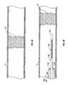
- FIG. 2 is an enlarged view of the indicated area of detail of FIG. 1 , illustrating the thrombectomy catheter system in a first condition
- FIG. 3 is an enlarged view of the indicated area of detail of FIG. 1 , illustrating the thrombectomy catheter system in a second condition;
- FIGS. 4A-4D illustrate a generalized sequence of steps for use of the thrombectomy catheter system of FIGS. 1-3 for restoration of flow past the occluded site;
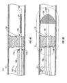
- FIG. 5 is an enlarged schematic illustration of the thrombectomy catheter system of FIG. 4D , shown in a deployed condition within a blood vessel;
- FIG. 6 is an enlarged schematic illustration of a thrombectomy catheter system, in accordance with another embodiment of the present disclosure, shown in a deployed condition within a blood vessel.
- the present disclosure provides for devices for ablating a blockage and for preventing the introduction of emboli into the blood stream during and after surgery performed to reduce or ablate the blockage in the blood vessel.
- occlusion refers to both complete and partial blockages of the vessel.
- proximal refers to that portion of the device or apparatus located closest to the user
- distal refers to that portion of the device or apparatus located furthest from the user
- Thrombectomy catheter system 100 includes an elongate catheter sleeve 102 having a substantially tubular configuration.
- Catheter sleeve 102 defines a lumen 103 (see FIG. 2 ) extending at least substantially entirely therethrough.
- Catheter sleeve 102 includes a proximal end portion 106 connected to and/or supporting a handle, hub or manifold 104, and a distal end portion 108 configured for passage of an elongated shaft 120 therethrough.
- Catheter sleeve 102 is fabricated utilizing suitable technology to provide catheter sleeve walls having predetermined flexibility characteristics that can allow precise intravascular navigation, pushability and trackability.
- Thrombectomy catheter system 100 includes at least one electrode 110 disposed at and/or supported at distal end portion 108 of catheter sleeve 102.
- a pair of electrodes 110a,110b is provided at distal end portion 108 of catheter sleeve 102.
- Each electrode 110a, 110b is electrically connectable to a source of electrosurgical energy, such as, for example, an electrosurgical generator "G", via electrical conduits or wires 112 extending through lumen 103 of catheter sleeve 102 and through hub 104.
- Each electrode 110 may be electrically isolated and/or independent from one another.
- electrodes 110a, 110b are preferably used to emulsify emboli or thrombi entrained in fluid flows (i.e., vessels) to prevent clogging of the channel or to ablate the embolus or thrombus to unclog the channel.
- thrombectomy catheter system 100 further includes a shaft or guidewire 120 extendable through lumen 103 of catheter sleeve 102.
- Guidewire 120 includes a selectively deployable capture element 124 disposed proximate distal end 122 thereof.
- capture element 124 is in the form of a filter or cage.
- Capture element 124 includes a first condition wherein capture element 124 is collapsed or retracted onto guidewire 120, and at least a second condition wherein capture element 124 is deployed or expanded to preferably span the entire lumen of the vessel or expand into apposition with the targeted vessel. Transformation of capture element 124 may be impelled by external mechanical means, or by self-activating memory material provided within capture element 124.
- Such mechanical memory may be imparted to the material of capture element 124 by thermal treatment to achieve a spring temper in stainless steel, for example, or to set a shape memory in a susceptible metal alloy, such as a binary nickel-titanium (nitinol) alloy.
- a susceptible metal alloy such as a binary nickel-titanium (nitinol) alloy.
- guidewire 120 in use, as will be described in greater detail below, guidewire 120 is inserted into the lumen of catheter sleeve 102, through hub 104, and slidably advanced therethrough until distal end 122 of guidewire 120 extends out through distal end portion of catheter sleeve 102 and capture element 124 is positioned at or near a desired location within the vessel.
- catheter system 100 may also be a fixed-wire system or a rapid exchange system.
- FIG. 4A schematically depicts a vessel "V" containing a blockage or clot "B" (e.g., a thrombus, embolus, etc.) completely or substantially restricting blood flow therethrough.
- a blockage or clot "B” e.g., a thrombus, embolus, etc.
- distal end portion 108 of catheter sleeve 102 is introduced into vessel "V" using any suitable technique.
- a goal of the surgical procedure is to position capture element 124 of guidewire 120 distal of blockage "B", and to position distal end portion 108, and more particularly electrodes 110, against and/or within blockage "B".
- catheter sleeve 102 is advanced through vessel “V” until electrodes 110, disposed at distal end portion 108, are in close proximity to, are in contact with, or are positioned within, blockage "B".
- distal end 122 of guidewire 120 is advanced through blockage "B” until capture element 124 is disposed distal of blockage "B".
- capture element 124 of guidewire 120 As seen in FIG. 4D , with capture element 124 of guidewire 120 located distally of blockage "B", capture element 124 is deployed to span the entire lumen of vessel "V". Once capture element 124 has been deployed, energy (e.g., thermal, RF, ultrasonic, electrical, plasma, etc.) is delivered to blockage “B” via electrodes 110. An effective amount of energy is delivered to electrodes 110 for an effective amount of time to ablate blockage "B". During and following ablation of blockage "B", any particularized thrombus and/or vapor, resulting from the ablation, is captured in capture element 124 of guidewire 120. In one embodiment, capture element 124 of guidewire 120 functions to trap and remove particles and/or debris that may flow distally or downstream through vessel "V" during the thrombectomy procedure.
- energy e.g., thermal, RF, ultrasonic, electrical, plasma, etc.
- each electrode 110 may be electrically isolated and/or independent from one another. Accordingly, it is envisioned and within the scope of the present disclosure for each electrode 110 to be independently controlled by electrosurgical generator "G". During the procedure, it may be desirable to limit current flow to and between electrodes 110 when a low impedance path exists between electrodes 110 and a return or common electrode and/or when a high impedance path exists between electrodes 110 and a return or common electrode. Desirably, the energy delivered to electrodes 110 is in the range from about 20 kHz to about 20 MHz, and in the range of from about 5 volts to about 300 volts (RMS).
- RMS volts
- At least one or each electrode 110 may be configured to deliver plasma or the like.
- the surrounding blood or other suitable fluid media may be the medium for generating the plasma.
- radio-opaque markers may be provided along the length of catheter sleeve 102 and/or guidewire 120.
- the position and location of the various elements of thrombectomy catheter system 100 e.g., electrodes 110, capture element 124, etc.
- conventional monitoring techniques such as, for example, fluoroscopy and the like.
- thrombectomy catheter system 100 has an overall gauge that is less than about 0.060 inches (1,52 mm). In this manner, thrombectomy catheter system 100 may enter and pass through present embolic protection devices that may be placed proximally of the blockage "B" during the thrombectomy procedure.
- Thrombectomy catheter system 200 includes a catheter sleeve or body 202 having a distal end portion 208.
- Thrombectomy catheter system 200 further includes at least a pair of electrodes 210a, 210b disposed or supported thereon. Desirably, electrodes 210a, 210b are spaced an axial distance from one another and are preferably located proximate distal end portion 208.
- Electrodes 210a, 210b While only a pair of electrodes 210a, 210b are shown and described as being disposed on catheter sleeve 202, it is within the scope of the present disclosure for any suitable number of electrodes to be disposed along the length of catheter sleeve 202.
- each electrode 210a or 210b may be electrically isolated from one another.
- radio-opaque markers 211 may be provided along the length of catheter sleeve 202, desirably on either side of each electrode 210a, 210b. Markers 211 provide the user, under fluoroscopic visualization, with the ability to identify when at least a distal-most electrode 210 is located distally of blockage "B".
- each electrode 210a, 210b may substantially surround catheter sleeve 202.
- thrombectomy catheter system 200 further includes a capture element 224 disposed and/or supported on distal end portion 208 of catheter sleeve 202.
- Capture element 224 may be located distally of a distal-most electrode 210b.
- Capture element 224 is substantially similar to capture element 124 and will not be discussed in great detail hereinbelow.
- Capture element 224 is in the form of a filter or cage.
- Capture element 224 includes a first condition wherein capture element 224 is collapsed or retracted onto catheter sleeve 202, and at least a second condition wherein capture element 224 is deployed or expanded to preferably span the entire lumen of the vessel or expands into apposition with the targeted vessel.
- thrombectomy catheter system 200 for performing a thrombectomy procedure, is shown and described. Once again, thrombectomy catheter system 200 is introduced into vessel "V" using any suitable technique.
- a goal of the surgical procedure of FIG. 6 is to position capture element 224 through and distal of blockage "B", and to position catheter sleeve 202 through blockage "B" such that at least one electrode, e.g., distal-most electrode 210b, is located distal or downstream of blockage "B” and such that at least one electrode, e.g., proximal-most electrode 210a, is located proximal of or upstream of blockage "B".
- catheter sleeve 202 is advanced through vessel “V” and through blockage "B” until distal-most electrode 210b is disposed distal of blockage "B” and capture element 224 is disposed distal of blockage "B".
- capture element 224 of thrombectomy catheter system 200 located distally of blockage "B"
- capture element 224 is deployed to span the entire lumen of vessel "V”.
- energy e.g., thermal, RF, ultrasonic, electrical, etc.
- An effective amount of energy is delivered to and between electrodes 210a, 210b, from electrosurgical generator "G", for an effective amount of time to ablate blockage "B".
- the effective amount of energy is transmitted through blockage "B” between distal-most electrode 210b and proximal-most electrode 210a.
- capture element 224 functions to trap and remove particles and/or debris that may flow distally or downstream through vessel "V" during the thrombectomy procedure.
- devices of the present disclosure have been directed to thrombectomy procedures and the like, it is within the present disclosure for the devices disclosed herein to be used in connection with other procedures equally as well, such as, for example, vascular stenosis, plaque removal, artherectomy and the like.
Landscapes
- Health & Medical Sciences (AREA)
- Engineering & Computer Science (AREA)
- Life Sciences & Earth Sciences (AREA)
- Surgery (AREA)
- General Health & Medical Sciences (AREA)
- Cardiology (AREA)
- Heart & Thoracic Surgery (AREA)
- Biomedical Technology (AREA)
- Veterinary Medicine (AREA)
- Animal Behavior & Ethology (AREA)
- Public Health (AREA)
- Physics & Mathematics (AREA)
- Plasma & Fusion (AREA)
- Nuclear Medicine, Radiotherapy & Molecular Imaging (AREA)
- Otolaryngology (AREA)
- Medical Informatics (AREA)
- Molecular Biology (AREA)
- Oral & Maxillofacial Surgery (AREA)
- Transplantation (AREA)
- Vascular Medicine (AREA)
- Surgical Instruments (AREA)
Claims (9)
- Système de cathéter (100) pour produire une ablation d'un blocage partiel ou complet (B) d'un vaisseau corporel (V), le Système de cathéter (100) comprenant :un manchon de cathéter (102) définissant un canal intérieur (103) s'étendant à travers celui-ci, le manchon de cathéter (102) définissant une portion d'extrémité distale (108) et une portion d'extrémité proximal (106) au moins une paire d'électrodes (110a, 110b) etun fil-guide (120) disposé de manière coulissante dans le canal intérieur (103) du manchon de cathéter (102), le fil-guide (120) comprenant un élément de capture (124) supporté près d'une extrémité distale de celui-ci (122), dans lequel le fil-guide (120) peut coulisser relativement au manchon de cathéter (102) pour exposer l'élément de capture (124) depuis la portion d'extrémité distale (108) du manchon de cathéter (102);dans lequel l'élément de capture (124) comprend une première condition dans laquelle l'élément de capture (124) est rétracté sur le fil-guide (120) et une seconde condition dans laquelle l'élément de capture (124) s'étend au moins sensiblement sur tout le canal intérieur du vaisseau (V),dans lequel l'élément de capture (124) forme une cage quand il est dans la seconde condition, caractérisé en ce que lesdites électrodes sont supportées sur le manchon de cathéter (102).
- Système de cathéter (100) selon la revendication 1, dans lequel chaque électrode (110a, 110b) est isolée de l'autre.
- Système de cathéter (100) selon la revendication 1 ou 2, dans lequel chaque électrode (110a, 110b) peut être électriquement raccordée à une source d'énergie électro-chirurgicale (G).
- Système de cathéter (100) selon l'une quelconque des revendications précédentes, comprenant en outre un raccord (104) supporté sur l'extrémité proximate (106) du manchon de cathéter (102).
- Système de cathéter (100) selon l'une quelconque des revendications précédentes, dans lequel le manchon de cathéter (102) est flexible et permet qu'il soit poussé et suivi.
- Système de cathéter (100) selon l'une quelconque des revendications précédentes, comprenant en outre une source d'énergie électro-chirurgicale (G) pouvant être connectée électriquement à chaque électrode (110a, 110b).
- Système de cathéter (100) selon l'une quelconque des revendications précédentes, dans lequel la source d'énergie électro-chirurgicale (G) fournit une quantité efficace d'énergie aux électrodes (110a, 110b) pour produire l'ablation du blocage (B).
- Système de cathéter (100) selon l'une quelconque des revendications précédentes, dans lequel le manchon de cathéter (102) a un calibre d'environ 1,52 mm (0,060 pouce).
- Système de cathéter (100) selon l'une quelconque des revendications précédentes, dans lequel des marqueurs radio-opaques (211) sont disposés le long du manchon de cathéter (102, 202) de chaque côté de chaque électrode (210a, 210b).
Applications Claiming Priority (1)
| Application Number | Priority Date | Filing Date | Title |
|---|---|---|---|
| US66683005P | 2005-03-31 | 2005-03-31 |
Publications (3)
| Publication Number | Publication Date |
|---|---|
| EP1707148A2 EP1707148A2 (fr) | 2006-10-04 |
| EP1707148A3 EP1707148A3 (fr) | 2007-09-05 |
| EP1707148B1 true EP1707148B1 (fr) | 2012-02-15 |
Family
ID=36693583
Family Applications (1)
| Application Number | Title | Priority Date | Filing Date |
|---|---|---|---|
| EP06006962A Ceased EP1707148B1 (fr) | 2005-03-31 | 2006-03-31 | Système à cathéter pour la thrombectomie intravasculaire à radio-fréquence par voie percutane ou par chirurgie et la méthode |
Country Status (5)
| Country | Link |
|---|---|
| US (2) | US7749220B2 (fr) |
| EP (1) | EP1707148B1 (fr) |
| AT (1) | ATE545378T1 (fr) |
| AU (1) | AU2006201354A1 (fr) |
| CA (1) | CA2541321A1 (fr) |
Cited By (1)
| Publication number | Priority date | Publication date | Assignee | Title |
|---|---|---|---|---|
| CN107847239A (zh) * | 2015-06-06 | 2018-03-27 | 香港科技大学 | 射频电血栓清除装置 |
Families Citing this family (51)
| Publication number | Priority date | Publication date | Assignee | Title |
|---|---|---|---|---|
| US8361067B2 (en) | 2002-09-30 | 2013-01-29 | Relievant Medsystems, Inc. | Methods of therapeutically heating a vertebral body to treat back pain |
| US7258690B2 (en) | 2003-03-28 | 2007-08-21 | Relievant Medsystems, Inc. | Windowed thermal ablation probe |
| US6907884B2 (en) | 2002-09-30 | 2005-06-21 | Depay Acromed, Inc. | Method of straddling an intraosseous nerve |
| US8246649B2 (en) * | 2008-03-19 | 2012-08-21 | Schneider M Bret | Electrostatic vascular filters |
| AU2009279451B2 (en) | 2008-08-08 | 2016-03-03 | Incept, Llc | Apparatus and methods for accessing and removing material from body lumens |
| US10028753B2 (en) | 2008-09-26 | 2018-07-24 | Relievant Medsystems, Inc. | Spine treatment kits |
| EP2339972B1 (fr) | 2008-09-26 | 2018-04-11 | Relievant Medsystems, Inc. | Systèmes pour piloter un instrument à travers un os |
| US9144455B2 (en) | 2010-06-07 | 2015-09-29 | Just Right Surgical, Llc | Low power tissue sealing device and method |
| WO2012158864A1 (fr) * | 2011-05-18 | 2012-11-22 | St. Jude Medical, Inc. | Appareil et procédé d'évaluation de la dénervation transvasculaire |
| US8909316B2 (en) | 2011-05-18 | 2014-12-09 | St. Jude Medical, Cardiology Division, Inc. | Apparatus and method of assessing transvascular denervation |
| US11311332B2 (en) * | 2011-08-23 | 2022-04-26 | Magneto Thrombectomy Solutions Ltd. | Thrombectomy devices |
| US10390877B2 (en) | 2011-12-30 | 2019-08-27 | Relievant Medsystems, Inc. | Systems and methods for treating back pain |
| US9192426B2 (en) | 2012-06-26 | 2015-11-24 | Covidien Lp | Ablation device having an expandable chamber for anchoring the ablation device to tissue |
| US10588691B2 (en) | 2012-09-12 | 2020-03-17 | Relievant Medsystems, Inc. | Radiofrequency ablation of tissue within a vertebral body |
| EP2914186B1 (fr) | 2012-11-05 | 2019-03-13 | Relievant Medsystems, Inc. | Système de création de chemins incurvés à travers un os et de modulation des nerfs au sein de l'os |
| CN104812322B (zh) | 2012-12-20 | 2018-12-11 | 雷纳尔动力有限公司 | 多点治疗探针及其使用方法 |
| EP2967614B1 (fr) | 2013-03-15 | 2016-11-30 | National University of Ireland Galway | Dispositif adapté pour enlever des matières de l'intérieur de la lumière et de la paroi d'une lumière corporelle |
| US9724151B2 (en) | 2013-08-08 | 2017-08-08 | Relievant Medsystems, Inc. | Modulating nerves within bone using bone fasteners |
| EP3017775A1 (fr) | 2014-11-07 | 2016-05-11 | National University of Ireland, Galway | Dispositif de thrombectomie |
| US11259820B2 (en) * | 2016-09-07 | 2022-03-01 | Daniel Ezra Walzman | Methods and devices to ameliorate vascular obstruction |
| US11877752B2 (en) | 2016-09-07 | 2024-01-23 | Daniel Ezra Walzman | Filterless aspiration, irrigating, macerating, rotating microcatheter and method of use |
| US10314684B2 (en) * | 2016-09-07 | 2019-06-11 | Daniel Ezra Walzman | Simultaneous rotating separator, irrigator microcatheter for thrombectomy |
| US10299824B2 (en) * | 2016-09-07 | 2019-05-28 | Daniel Ezra Walzman | Rotating separator, irrigator microcatheter for thrombectomy |
| US11439492B2 (en) | 2016-09-07 | 2022-09-13 | Daniel Ezra Walzman | Lasso filter tipped microcatheter for simultaneous rotating separator, irrigator for thrombectomy and method for use |
| US12029475B2 (en) | 2017-03-22 | 2024-07-09 | Magneto Thrombectomy Solutions Ltd. | Thrombectomy using both electrostatic and suction forces |
| EP3713507B1 (fr) | 2017-11-23 | 2023-08-02 | Magneto Thrombectomy Solutions Ltd. | Dispositifs tubulaires de thrombectomie |
| US10709463B2 (en) | 2017-12-11 | 2020-07-14 | Covidien Lp | Electrically enhanced retrieval of material from vessel lumens |
| US11058444B2 (en) | 2017-12-11 | 2021-07-13 | Covidien Lp | Electrically enhanced retrieval of material from vessel lumens |
| US11229451B2 (en) | 2017-12-13 | 2022-01-25 | Eric Raul GUERRA | Thrombectomy catheter and methods of use |
| US11134967B2 (en) | 2017-12-13 | 2021-10-05 | Eric Raul GUERRA | Thrombectomy catheter and methods of use |
| US11596769B2 (en) * | 2018-01-16 | 2023-03-07 | Daniel Ezra Walzman | Bypass catheter |
| US10799674B2 (en) | 2018-01-16 | 2020-10-13 | Daniel Ezra Walzman | Bypass catheter |
| US11596438B2 (en) * | 2018-01-16 | 2023-03-07 | Daniel Ezra Walzman | Bypass catheter |
| US11160571B2 (en) | 2018-06-22 | 2021-11-02 | Covidien Lp | Electrically enhanced retrieval of material from vessel lumens |
| USD904611S1 (en) | 2018-10-10 | 2020-12-08 | Bolder Surgical, Llc | Jaw design for a surgical instrument |
| US11612430B2 (en) | 2019-03-19 | 2023-03-28 | Covidien Lp | Electrically enhanced retrieval of material from vessel lumens |
| US11093038B2 (en) | 2019-05-14 | 2021-08-17 | Synchron Australia Pty Limited | Systems and methods for generic control using a neural signal |
| US11523838B2 (en) | 2019-06-12 | 2022-12-13 | Covidien Lp | Retrieval of material from corporeal lumens |
| US11191558B2 (en) | 2019-06-12 | 2021-12-07 | Covidien Lp | Retrieval of material from corporeal lumens |
| WO2021050767A1 (fr) | 2019-09-12 | 2021-03-18 | Relievant Medsystems, Inc. | Systèmes et méthodes de modulation de tissu |
| EP4048371A4 (fr) | 2019-10-29 | 2024-03-13 | Synchron Australia Pty Ltd | Systèmes et procédés pour configurer une interface de commande cérébrale à l'aide de données provenant de systèmes déployés |
| US11974752B2 (en) | 2019-12-12 | 2024-05-07 | Covidien Lp | Electrically enhanced retrieval of material from vessel lumens |
| US11395668B2 (en) | 2019-12-12 | 2022-07-26 | Covidien Lp | Electrically enhanced retrieval of material from vessel lumens |
| USD934423S1 (en) | 2020-09-11 | 2021-10-26 | Bolder Surgical, Llc | End effector for a surgical device |
| US12082876B1 (en) | 2020-09-28 | 2024-09-10 | Relievant Medsystems, Inc. | Introducer drill |
| JP2024505335A (ja) | 2020-12-22 | 2024-02-06 | リリーバント メドシステムズ、インコーポレイテッド | 脊椎神経調節の候補の予測 |
| US12004803B2 (en) | 2021-03-15 | 2024-06-11 | Covidien Lp | Thrombectomy treatment system |
| US11963713B2 (en) | 2021-06-02 | 2024-04-23 | Covidien Lp | Medical treatment system |
| US11944374B2 (en) | 2021-08-30 | 2024-04-02 | Covidien Lp | Electrical signals for retrieval of material from vessel lumens |
| US12076020B2 (en) | 2021-11-18 | 2024-09-03 | Covidien Lp | Retrieval of material from corporeal lumens |
| US20240081898A1 (en) * | 2022-09-14 | 2024-03-14 | Covidien Lp | Retrieval of material from vessel lumens |
Family Cites Families (17)
| Publication number | Priority date | Publication date | Assignee | Title |
|---|---|---|---|---|
| US5178620A (en) * | 1988-06-10 | 1993-01-12 | Advanced Angioplasty Products, Inc. | Thermal dilatation catheter and method |
| US5419767A (en) * | 1992-01-07 | 1995-05-30 | Thapliyal And Eggers Partners | Methods and apparatus for advancing catheters through severely occluded body lumens |
| US5972019A (en) * | 1996-07-25 | 1999-10-26 | Target Therapeutics, Inc. | Mechanical clot treatment device |
| US6202114B1 (en) * | 1997-12-31 | 2001-03-13 | Cisco Technology, Inc. | Spanning tree with fast link-failure convergence |
| US6622367B1 (en) * | 1998-02-03 | 2003-09-23 | Salient Interventional Systems, Inc. | Intravascular device and method of manufacture and use |
| US6522930B1 (en) | 1998-05-06 | 2003-02-18 | Atrionix, Inc. | Irrigated ablation device assembly |
| US6102908A (en) | 1999-01-04 | 2000-08-15 | Tu; Lily Chen | Rotatable apparatus having ablation capabilities |
| US7171263B2 (en) | 1999-06-04 | 2007-01-30 | Impulse Dynamics Nv | Drug delivery device |
| US7092753B2 (en) | 1999-06-04 | 2006-08-15 | Impulse Dynamics Nv | Drug delivery device |
| US6068645A (en) | 1999-06-07 | 2000-05-30 | Tu; Hosheng | Filter system and methods for removing blood clots and biological material |
| US6530939B1 (en) | 1999-07-30 | 2003-03-11 | Incept, Llc | Vascular device having articulation region and methods of use |
| US6544279B1 (en) * | 2000-08-09 | 2003-04-08 | Incept, Llc | Vascular device for emboli, thrombus and foreign body removal and methods of use |
| JP3559861B2 (ja) * | 2000-04-12 | 2004-09-02 | 信也 神山 | 血管内フィルター |
| DE60130497T2 (de) * | 2001-06-28 | 2008-05-29 | Lithotech Medical Ltd. | Vorrichtung zum einfangen von fremdkörpern |
| US20030114747A1 (en) * | 2001-12-14 | 2003-06-19 | Smith Scott R. | Recanalization of occluded vessel using magnetic resonance guidance |
| US20030236533A1 (en) * | 2002-06-20 | 2003-12-25 | The Regents Of The University Of California | Shape memory polymer actuator and catheter |
| DE202004021953U1 (de) * | 2003-09-12 | 2013-06-19 | Vessix Vascular, Inc. | Auswählbare exzentrische Remodellierung und/oder Ablation von atherosklerotischem Material |
-
2006
- 2006-03-28 CA CA002541321A patent/CA2541321A1/fr not_active Abandoned
- 2006-03-28 US US11/391,620 patent/US7749220B2/en not_active Expired - Fee Related
- 2006-03-31 EP EP06006962A patent/EP1707148B1/fr not_active Ceased
- 2006-03-31 AT AT06006962T patent/ATE545378T1/de active
- 2006-03-31 AU AU2006201354A patent/AU2006201354A1/en not_active Abandoned
-
2010
- 2010-05-25 US US12/787,274 patent/US8038674B2/en not_active Expired - Fee Related
Cited By (1)
| Publication number | Priority date | Publication date | Assignee | Title |
|---|---|---|---|---|
| CN107847239A (zh) * | 2015-06-06 | 2018-03-27 | 香港科技大学 | 射频电血栓清除装置 |
Also Published As
| Publication number | Publication date |
|---|---|
| US20100234842A1 (en) | 2010-09-16 |
| US7749220B2 (en) | 2010-07-06 |
| US20060224155A1 (en) | 2006-10-05 |
| CA2541321A1 (fr) | 2006-09-30 |
| EP1707148A3 (fr) | 2007-09-05 |
| AU2006201354A1 (en) | 2006-10-19 |
| ATE545378T1 (de) | 2012-03-15 |
| EP1707148A2 (fr) | 2006-10-04 |
| US8038674B2 (en) | 2011-10-18 |
Similar Documents
| Publication | Publication Date | Title |
|---|---|---|
| EP1707148B1 (fr) | Système à cathéter pour la thrombectomie intravasculaire à radio-fréquence par voie percutane ou par chirurgie et la méthode | |
| JP6785832B2 (ja) | 高周波エネルギを用いた閉塞血管再疎通術 | |
| US6319242B1 (en) | Apparatus and method for controlled removal of stenotic material from stents | |
| JP6211576B2 (ja) | 高周波エネルギーを用いた閉塞した血管の再疎通 | |
| US5941869A (en) | Apparatus and method for controlled removal of stenotic material from stents | |
| US6929652B1 (en) | Delivery and recovery systems having steerability and rapid exchange operating modes for embolic protection systems | |
| EP2496165B1 (fr) | Dispositif de remodelage luminal | |
| US20110196414A1 (en) | Multimode occlusion and stenosis treatment apparatus and method of use | |
| JPH02503161A (ja) | 展張式引戻アセレクトミーカテーテルシステム | |
| JP2003517870A (ja) | 血管内閉塞潅注カテーテルとその使用方法 | |
| JP2021069933A (ja) | 血栓除去及びステント留置システム | |
| EP2785288B1 (fr) | Dispositif de traitement de lésions |
Legal Events
| Date | Code | Title | Description |
|---|---|---|---|
| PUAI | Public reference made under article 153(3) epc to a published international application that has entered the european phase |
Free format text: ORIGINAL CODE: 0009012 |
|
| AK | Designated contracting states |
Kind code of ref document: A2 Designated state(s): AT BE BG CH CY CZ DE DK EE ES FI FR GB GR HU IE IS IT LI LT LU LV MC NL PL PT RO SE SI SK TR |
|
| AX | Request for extension of the european patent |
Extension state: AL BA HR MK YU |
|
| PUAL | Search report despatched |
Free format text: ORIGINAL CODE: 0009013 |
|
| RAP1 | Party data changed (applicant data changed or rights of an application transferred) |
Owner name: COVIDIEN AG |
|
| AK | Designated contracting states |
Kind code of ref document: A3 Designated state(s): AT BE BG CH CY CZ DE DK EE ES FI FR GB GR HU IE IS IT LI LT LU LV MC NL PL PT RO SE SI SK TR |
|
| AX | Request for extension of the european patent |
Extension state: AL BA HR MK YU |
|
| 17P | Request for examination filed |
Effective date: 20080222 |
|
| 17Q | First examination report despatched |
Effective date: 20080326 |
|
| AKX | Designation fees paid |
Designated state(s): AT BE BG CH CY CZ DE DK EE ES FI FR GB GR HU IE IS IT LI LT LU LV MC NL PL PT RO SE SI SK TR |
|
| GRAP | Despatch of communication of intention to grant a patent |
Free format text: ORIGINAL CODE: EPIDOSNIGR1 |
|
| GRAS | Grant fee paid |
Free format text: ORIGINAL CODE: EPIDOSNIGR3 |
|
| GRAA | (expected) grant |
Free format text: ORIGINAL CODE: 0009210 |
|
| AK | Designated contracting states |
Kind code of ref document: B1 Designated state(s): AT BE BG CH CY CZ DE DK EE ES FI FR GB GR HU IE IS IT LI LT LU LV MC NL PL PT RO SE SI SK TR |
|
| REG | Reference to a national code |
Ref country code: GB Ref legal event code: FG4D Ref country code: CH Ref legal event code: EP |
|
| REG | Reference to a national code |
Ref country code: IE Ref legal event code: FG4D |
|
| REG | Reference to a national code |
Ref country code: AT Ref legal event code: REF Ref document number: 545378 Country of ref document: AT Kind code of ref document: T Effective date: 20120315 |
|
| REG | Reference to a national code |
Ref country code: DE Ref legal event code: R096 Ref document number: 602006027607 Country of ref document: DE Effective date: 20120412 |
|
| REG | Reference to a national code |
Ref country code: NL Ref legal event code: VDEP Effective date: 20120215 |
|
| LTIE | Lt: invalidation of european patent or patent extension |
Effective date: 20120215 |
|
| PG25 | Lapsed in a contracting state [announced via postgrant information from national office to epo] |
Ref country code: LT Free format text: LAPSE BECAUSE OF FAILURE TO SUBMIT A TRANSLATION OF THE DESCRIPTION OR TO PAY THE FEE WITHIN THE PRESCRIBED TIME-LIMIT Effective date: 20120215 Ref country code: NL Free format text: LAPSE BECAUSE OF FAILURE TO SUBMIT A TRANSLATION OF THE DESCRIPTION OR TO PAY THE FEE WITHIN THE PRESCRIBED TIME-LIMIT Effective date: 20120215 Ref country code: IS Free format text: LAPSE BECAUSE OF FAILURE TO SUBMIT A TRANSLATION OF THE DESCRIPTION OR TO PAY THE FEE WITHIN THE PRESCRIBED TIME-LIMIT Effective date: 20120615 |
|
| PG25 | Lapsed in a contracting state [announced via postgrant information from national office to epo] |
Ref country code: PT Free format text: LAPSE BECAUSE OF FAILURE TO SUBMIT A TRANSLATION OF THE DESCRIPTION OR TO PAY THE FEE WITHIN THE PRESCRIBED TIME-LIMIT Effective date: 20120615 Ref country code: BE Free format text: LAPSE BECAUSE OF FAILURE TO SUBMIT A TRANSLATION OF THE DESCRIPTION OR TO PAY THE FEE WITHIN THE PRESCRIBED TIME-LIMIT Effective date: 20120215 Ref country code: LV Free format text: LAPSE BECAUSE OF FAILURE TO SUBMIT A TRANSLATION OF THE DESCRIPTION OR TO PAY THE FEE WITHIN THE PRESCRIBED TIME-LIMIT Effective date: 20120215 Ref country code: FI Free format text: LAPSE BECAUSE OF FAILURE TO SUBMIT A TRANSLATION OF THE DESCRIPTION OR TO PAY THE FEE WITHIN THE PRESCRIBED TIME-LIMIT Effective date: 20120215 Ref country code: PL Free format text: LAPSE BECAUSE OF FAILURE TO SUBMIT A TRANSLATION OF THE DESCRIPTION OR TO PAY THE FEE WITHIN THE PRESCRIBED TIME-LIMIT Effective date: 20120215 Ref country code: GR Free format text: LAPSE BECAUSE OF FAILURE TO SUBMIT A TRANSLATION OF THE DESCRIPTION OR TO PAY THE FEE WITHIN THE PRESCRIBED TIME-LIMIT Effective date: 20120516 |
|
| REG | Reference to a national code |
Ref country code: AT Ref legal event code: MK05 Ref document number: 545378 Country of ref document: AT Kind code of ref document: T Effective date: 20120215 |
|
| PG25 | Lapsed in a contracting state [announced via postgrant information from national office to epo] |
Ref country code: CY Free format text: LAPSE BECAUSE OF FAILURE TO SUBMIT A TRANSLATION OF THE DESCRIPTION OR TO PAY THE FEE WITHIN THE PRESCRIBED TIME-LIMIT Effective date: 20120215 |
|
| PGFP | Annual fee paid to national office [announced via postgrant information from national office to epo] |
Ref country code: IT Payment date: 20120323 Year of fee payment: 7 |
|
| PG25 | Lapsed in a contracting state [announced via postgrant information from national office to epo] |
Ref country code: MC Free format text: LAPSE BECAUSE OF NON-PAYMENT OF DUE FEES Effective date: 20120331 Ref country code: SE Free format text: LAPSE BECAUSE OF FAILURE TO SUBMIT A TRANSLATION OF THE DESCRIPTION OR TO PAY THE FEE WITHIN THE PRESCRIBED TIME-LIMIT Effective date: 20120215 Ref country code: EE Free format text: LAPSE BECAUSE OF FAILURE TO SUBMIT A TRANSLATION OF THE DESCRIPTION OR TO PAY THE FEE WITHIN THE PRESCRIBED TIME-LIMIT Effective date: 20120215 Ref country code: SI Free format text: LAPSE BECAUSE OF FAILURE TO SUBMIT A TRANSLATION OF THE DESCRIPTION OR TO PAY THE FEE WITHIN THE PRESCRIBED TIME-LIMIT Effective date: 20120215 Ref country code: RO Free format text: LAPSE BECAUSE OF FAILURE TO SUBMIT A TRANSLATION OF THE DESCRIPTION OR TO PAY THE FEE WITHIN THE PRESCRIBED TIME-LIMIT Effective date: 20120215 Ref country code: CZ Free format text: LAPSE BECAUSE OF FAILURE TO SUBMIT A TRANSLATION OF THE DESCRIPTION OR TO PAY THE FEE WITHIN THE PRESCRIBED TIME-LIMIT Effective date: 20120215 Ref country code: DK Free format text: LAPSE BECAUSE OF FAILURE TO SUBMIT A TRANSLATION OF THE DESCRIPTION OR TO PAY THE FEE WITHIN THE PRESCRIBED TIME-LIMIT Effective date: 20120215 |
|
| REG | Reference to a national code |
Ref country code: CH Ref legal event code: PL |
|
| PG25 | Lapsed in a contracting state [announced via postgrant information from national office to epo] |
Ref country code: SK Free format text: LAPSE BECAUSE OF FAILURE TO SUBMIT A TRANSLATION OF THE DESCRIPTION OR TO PAY THE FEE WITHIN THE PRESCRIBED TIME-LIMIT Effective date: 20120215 |
|
| PLBE | No opposition filed within time limit |
Free format text: ORIGINAL CODE: 0009261 |
|
| STAA | Information on the status of an ep patent application or granted ep patent |
Free format text: STATUS: NO OPPOSITION FILED WITHIN TIME LIMIT |
|
| 26N | No opposition filed |
Effective date: 20121116 |
|
| PG25 | Lapsed in a contracting state [announced via postgrant information from national office to epo] |
Ref country code: CH Free format text: LAPSE BECAUSE OF NON-PAYMENT OF DUE FEES Effective date: 20120331 Ref country code: AT Free format text: LAPSE BECAUSE OF FAILURE TO SUBMIT A TRANSLATION OF THE DESCRIPTION OR TO PAY THE FEE WITHIN THE PRESCRIBED TIME-LIMIT Effective date: 20120215 Ref country code: LI Free format text: LAPSE BECAUSE OF NON-PAYMENT OF DUE FEES Effective date: 20120331 |
|
| REG | Reference to a national code |
Ref country code: DE Ref legal event code: R097 Ref document number: 602006027607 Country of ref document: DE Effective date: 20121116 |
|
| PGFP | Annual fee paid to national office [announced via postgrant information from national office to epo] |
Ref country code: ES Payment date: 20120326 Year of fee payment: 7 |
|
| PG25 | Lapsed in a contracting state [announced via postgrant information from national office to epo] |
Ref country code: BG Free format text: LAPSE BECAUSE OF FAILURE TO SUBMIT A TRANSLATION OF THE DESCRIPTION OR TO PAY THE FEE WITHIN THE PRESCRIBED TIME-LIMIT Effective date: 20120515 |
|
| PG25 | Lapsed in a contracting state [announced via postgrant information from national office to epo] |
Ref country code: IT Free format text: LAPSE BECAUSE OF NON-PAYMENT OF DUE FEES Effective date: 20130331 |
|
| PG25 | Lapsed in a contracting state [announced via postgrant information from national office to epo] |
Ref country code: TR Free format text: LAPSE BECAUSE OF FAILURE TO SUBMIT A TRANSLATION OF THE DESCRIPTION OR TO PAY THE FEE WITHIN THE PRESCRIBED TIME-LIMIT Effective date: 20120215 |
|
| PG25 | Lapsed in a contracting state [announced via postgrant information from national office to epo] |
Ref country code: LU Free format text: LAPSE BECAUSE OF NON-PAYMENT OF DUE FEES Effective date: 20120331 |
|
| PG25 | Lapsed in a contracting state [announced via postgrant information from national office to epo] |
Ref country code: HU Free format text: LAPSE BECAUSE OF FAILURE TO SUBMIT A TRANSLATION OF THE DESCRIPTION OR TO PAY THE FEE WITHIN THE PRESCRIBED TIME-LIMIT Effective date: 20060331 |
|
| REG | Reference to a national code |
Ref country code: FR Ref legal event code: PLFP Year of fee payment: 10 |
|
| PG25 | Lapsed in a contracting state [announced via postgrant information from national office to epo] |
Ref country code: ES Free format text: LAPSE BECAUSE OF THE APPLICANT RENOUNCES Effective date: 20120803 |
|
| REG | Reference to a national code |
Ref country code: FR Ref legal event code: PLFP Year of fee payment: 11 |
|
| REG | Reference to a national code |
Ref country code: FR Ref legal event code: PLFP Year of fee payment: 12 |
|
| REG | Reference to a national code |
Ref country code: FR Ref legal event code: PLFP Year of fee payment: 13 |
|
| PGFP | Annual fee paid to national office [announced via postgrant information from national office to epo] |
Ref country code: DE Payment date: 20200218 Year of fee payment: 15 Ref country code: IE Payment date: 20200227 Year of fee payment: 15 Ref country code: GB Payment date: 20200221 Year of fee payment: 15 |
|
| PGFP | Annual fee paid to national office [announced via postgrant information from national office to epo] |
Ref country code: FR Payment date: 20200220 Year of fee payment: 15 |
|
| REG | Reference to a national code |
Ref country code: DE Ref legal event code: R119 Ref document number: 602006027607 Country of ref document: DE |
|
| GBPC | Gb: european patent ceased through non-payment of renewal fee |
Effective date: 20210331 |
|
| PG25 | Lapsed in a contracting state [announced via postgrant information from national office to epo] |
Ref country code: DE Free format text: LAPSE BECAUSE OF NON-PAYMENT OF DUE FEES Effective date: 20211001 Ref country code: IE Free format text: LAPSE BECAUSE OF NON-PAYMENT OF DUE FEES Effective date: 20210331 Ref country code: FR Free format text: LAPSE BECAUSE OF NON-PAYMENT OF DUE FEES Effective date: 20210331 Ref country code: GB Free format text: LAPSE BECAUSE OF NON-PAYMENT OF DUE FEES Effective date: 20210331 |