EP1707073A2 - Verfahren zum Herstellen eines Rucksacks und nach diesem Verfahren hergestellter Rucksack - Google Patents
Verfahren zum Herstellen eines Rucksacks und nach diesem Verfahren hergestellter Rucksack Download PDFInfo
- Publication number
- EP1707073A2 EP1707073A2 EP20060005131 EP06005131A EP1707073A2 EP 1707073 A2 EP1707073 A2 EP 1707073A2 EP 20060005131 EP20060005131 EP 20060005131 EP 06005131 A EP06005131 A EP 06005131A EP 1707073 A2 EP1707073 A2 EP 1707073A2
- Authority
- EP
- European Patent Office
- Prior art keywords
- panel
- backpack
- assembly
- bag
- auxiliary element
- Prior art date
- Legal status (The legal status is an assumption and is not a legal conclusion. Google has not performed a legal analysis and makes no representation as to the accuracy of the status listed.)
- Withdrawn
Links
- 238000000034 method Methods 0.000 title claims abstract description 20
- 238000004519 manufacturing process Methods 0.000 title claims description 7
- 239000000463 material Substances 0.000 claims abstract description 15
- 238000003466 welding Methods 0.000 claims abstract description 14
- 230000006835 compression Effects 0.000 claims description 17
- 238000007906 compression Methods 0.000 claims description 17
- 238000004026 adhesive bonding Methods 0.000 claims description 15
- 230000000712 assembly Effects 0.000 description 6
- 238000000429 assembly Methods 0.000 description 6
- 239000004744 fabric Substances 0.000 description 6
- 230000000694 effects Effects 0.000 description 4
- 238000009958 sewing Methods 0.000 description 3
- 230000003187 abdominal effect Effects 0.000 description 2
- 238000005299 abrasion Methods 0.000 description 2
- 239000000853 adhesive Substances 0.000 description 2
- 230000001070 adhesive effect Effects 0.000 description 2
- 238000009826 distribution Methods 0.000 description 2
- 239000006260 foam Substances 0.000 description 2
- 239000003292 glue Substances 0.000 description 2
- 230000008595 infiltration Effects 0.000 description 2
- 238000001764 infiltration Methods 0.000 description 2
- 238000007789 sealing Methods 0.000 description 2
- 239000004568 cement Substances 0.000 description 1
- 230000009194 climbing Effects 0.000 description 1
- 238000010276 construction Methods 0.000 description 1
- 230000005684 electric field Effects 0.000 description 1
- 230000004927 fusion Effects 0.000 description 1
- 239000012943 hotmelt Substances 0.000 description 1
- 239000007788 liquid Substances 0.000 description 1
- 239000002184 metal Substances 0.000 description 1
- 235000011837 pasties Nutrition 0.000 description 1
- 210000004197 pelvis Anatomy 0.000 description 1
- 238000003825 pressing Methods 0.000 description 1
- 230000002787 reinforcement Effects 0.000 description 1
- 230000003014 reinforcing effect Effects 0.000 description 1
- 238000007493 shaping process Methods 0.000 description 1
- 230000000087 stabilizing effect Effects 0.000 description 1
- 239000004753 textile Substances 0.000 description 1
- 238000002604 ultrasonography Methods 0.000 description 1
- XLYOFNOQVPJJNP-UHFFFAOYSA-N water Substances O XLYOFNOQVPJJNP-UHFFFAOYSA-N 0.000 description 1
Images




Classifications
-
- A—HUMAN NECESSITIES
- A45—HAND OR TRAVELLING ARTICLES
- A45F—TRAVELLING OR CAMP EQUIPMENT: SACKS OR PACKS CARRIED ON THE BODY
- A45F3/00—Travelling or camp articles; Sacks or packs carried on the body
- A45F3/04—Sacks or packs carried on the body by means of two straps passing over the two shoulders
Definitions
- the invention relates to the field of backpacks and their manufacturing processes.
- a backpack usually has a main compartment that delimits a closed (or at least resealable) volume for holding objects.
- the bag also comprises a carrying system (for example straps and possibly a belt, various reinforcement and support systems that facilitate a good distribution of loads), and it can include various accessories such as internal or external pockets, deployable parts, means for attaching various objects to the outside of the bag, etc.
- the main compartment consists of panels of flexible materials which are cut flat according to a pattern and assembled together by stitching.
- a portion of the panels forming the main compartment may consist of rigid or semi-rigid panels.
- the shape of the main compartment is paramount. Indeed, the shape of this compartment must participate in a good distribution of the weight of the load contained in the bag, it must ensure that the bag impedes the least possible mobility of the user, while also ensuring sufficient volume, and adapted to carry the objects usually necessary for the practice of the sport in question.
- this form is globally three-dimensional, and it is complex.
- a bag that would be three-dimensional and very simple to make would have a faceted shape, for example polyhedral. Such a shape, whose faces are flat, would be very simple to achieve, simply by assembling panels in lines of substantially rectilinear seams. However, such a shape would not achieve the desired volume, except to multiply the panels, and therefore the assemblies. However, each assembly represents a relatively expensive operation, and may also represent a zone of weakness or a zone of water infiltration.
- a pinched assembly consists of assembling, so as to superpose, two assembly lines (curves or straight lines) which, on the flat, on the patronage, are not contiguous (whether they are parallel or divergent).
- the pinched assembly can also be done when assembling two separate panels along lines of assembly which, flat on the patronage, can not be put in coincidence. We can then speak of extrinsic forceps.
- the pinch assembly will result in giving the (x) panel (x) a three-dimensional shape, while the panel is made of a material which, at the base, is two-dimensional, so planar.
- bonding is understood to mean both an assembly of two parts by an adhesive material interposed between the two parts, and a bonding by welding in which the two materials are assembled directly to one another under the effect of a local supply of energy, in the form of a thermal input, an electric field or under the effect of vibrations, for example for a high frequency bonding or ultrasound.
- the usable material may be a liquid or pasty adhesive, a cement, or a hot melt tape.
- connection by welding there is no supply of material between the two parts to be assembled. In any case, it is a seamless assembly technique.
- the invention therefore aims to propose new methods of manufacturing backpacks that can achieve, in a simple, reliable and economical way, backpacks with high technical characteristics.
- the invention also proposes a backpack, characterized in that it comprises at least one auxiliary element assembled to a main panel of flexible material by a first assembly by gluing or welding, said main panel being shaped in three-dimensional form by a pinched assembly.
- the auxiliary element may be a yoke (linked to the single main panel or also linked to at least one other panel), a compression system, a zipper, etc.
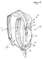
- FIGS. 1 and 2 show a backpack carrying bag 10 which comprises, on a dorsal surface 12 intended to come into contact with the back of the user, carrying means made in the form of a pair of straps 14 for carrying the bag on the shoulders.
- These carrying means may further comprise an abdominal belt 16 (here in the form of a simple strap) for stabilizing the bag and possibly to distribute a portion of the weight of the bag at the pelvis of the user.
- the bag 10 has a main compartment 18 of substantially parallelepiped shape, although in reality, the shape of this compartment is more complex.
- the main compartment 18 has, opposite its dorsal face 12, a front face 20 which is joined to the dorsal face 12 by two lateral faces 22.
- the main compartment 18 is therefore delimited by faces which are preferably made of a flexible material, for example a fabric.
- the back face 12 may comprise a reinforcing structure, for example a foam plate as will be described below, or a metal frame or rigid plastic.
- the bag is provided with a compression system 19 comprising adjustable length straps which connect the front face 20 of the bag to the back face 12, in order to compress the main compartment 18 and to reduce the the thickness of the bag when it is not full. It could also comprise, in the center and at the top of its dorsal face 12, a hooking loop which can be used either to hang the bag (for example at a peak) or to take the bag by hand.
- a compression system 19 comprising adjustable length straps which connect the front face 20 of the bag to the back face 12, in order to compress the main compartment 18 and to reduce the the thickness of the bag when it is not full. It could also comprise, in the center and at the top of its dorsal face 12, a hooking loop which can be used either to hang the bag (for example at a peak) or to take the bag by hand.
- the compartment 18 is closed at its lower part by a fixed bottom 26.
- the main compartment 18 is open at its upper end.
- the upper opening is defined by a tubular skirt 24 which extends upwardly the front, rear and side faces of the main compartment.
- the closure of the bag is obtained simply by folding the tubular skirt 24 on itself and by hooking the folded skirt on the lateral faces of the bag, the upper edge of the skirt being provided with a rod semi-rigid sealing.
- the upper end edge of the skirt could be provided with a drawstring for closing the upper opening in the manner of a diaphragm and, to complete the sealing of the closure, it could be provided a upper flap covering this reclosable opening.
- the backpack is composed of essentially two panels 28, 30, which are illustrated in Figures 3 and 4.
- the rear panel 28, previously cut according to a pattern as shown flat in FIG. 3, is intended to form the back face 12 and the bottom 26 of the main compartment 18. It comprises an upper edge 28a, two lateral edges 28b and a lower edge 28c. In its lateral edges, two V-shaped cuts 28d can be seen whose edges facing each other are intended to be joined by a pinched assembly, so as to give the rear panel 28 a three-dimensional shape encompassing the dorsal face 12 and the 26. The notches 28d are thus arranged near the boundary between the dorsal surface 12 and the bottom 26.
- the front panel 30, previously cut according to a pattern as shown in FIG. 4, is intended to form the front face 20 and the two lateral faces 22 of the compartment. It thus comprises an upper edge 30a, two lateral edges 30b (which are in this case curves), and a lower edge 30c.
- the two front 30 and rear 28 panels are assembled along their respective side and bottom edges, for example by a seam.
- the upper edges 28a, 30a could form the upper edge of the bag delimiting the resealable opening.
- the tubular upper skirt 24 of the bag is formed by an additional panel (not shown) assembled along the upper edges 28a, 30a of the rear panels 28 and before 30.
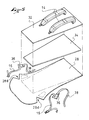
- the carrying system can be assembled on the outer face of the panel 28.
- an auxiliary carrying panel 32 on which the top of the straps 14 is pre-assembled, is intended to be fixed by its members. edges against the outer face of the panel back.
- a stiffening structure 34 (for example a foam and / or plastic plate) is interposed, for example, between the rear panel 28 and the auxiliary carrying panel 32.
- This panel may be carried by the back panel by stitching. , by gluing, by welding, etc.
- straps can be assembled on the rear panel 28, either directly on the panel, or, as in the example illustrated, by means of a wall lamp.
- sconces 36 on each of which are pre-assembled an element of the abdominal strap 16 and a strap 38 for adjusting the shoulder strap 14.
- the sconces 36 may be made of different flexible, rigid or semi-rigid materials. rigid and can be assembled by stitching, gluing or welding on the back panel 28.
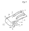
- FIG. 6 it is shown how, after the various auxiliary elements (carrying panel 32 and sconces 36) have been assembled on the rear panel 28, it is possible to three-dimensionally shape the rear panel 28. see that the edges of the notches 28d have been assembled to each other so as to close the clamp.
- This pinch assembly thus makes it possible to give the rear panel 28 a three-dimensional shape and it can be seen that it then forms both the dorsal surface 12 and the bottom 26 of the compartment 18.
- the pinched assembly can be made according to any known technique, by example by sewing, by gluing, etc.
- the assemblies of auxiliary elements on the rear panel 28 have been made while still in planar configuration. This is very advantageous in terms of ease of implementation, ensuring both reduced manufacturing times and, at the same time, a high accuracy of positioning.
- the assembly of these auxiliary elements uses bonding or welding techniques, which most often require pressing tools, it is then possible to use "flat" tools, and not three-dimensional tools.
- Flat tools are universal tools, whereas to make three-dimensional assemblies by gluing or welding, it is generally necessary to design three-dimensional tools specific to the assembly in question, or in any case non-universal.
- the compression system 19 is attached by gluing on the front face 20.
- the compression system comprises a first wall 40, which is in this case constituted by a yoke of fabric, on which compression straps 42 and tightening loops 44 are mounted.
- This appliqué is intended to be fixed on the front face 20.
- the main sconce 40 is arranged substantially at center of the front face 20 and it occupies about half of the area of the front face.
- the two compression straps 42 are anchored near the upper end of the side edges of the applique 40, for example by stitching.
- These compression straps 42 are intended to cooperate with clamping loops 46 which can be assembled on the lateral faces 22 of the bag, on the dorsal face 12, or, as illustrated in FIG. 1, which are mounted on legs flexible 48 fixed at the level of the assembly of the lateral edges of the front and rear panels, that is to say at the junctions between the lateral faces and the dorsal face of the bag.
- the compression system further comprises a second applique 50, smaller than the first 40 and which is intended to be fixed, preferably by gluing, in the lower part of the front face 18, substantially in the middle.
- This second applies 50 carries two lower compression straps 52 which are intended to pass in return loops 56 (also fixed on flexible tabs 48 taken in the assembly of front and rear panels), then to engage in the tightening loops 44 located at the bottom of the main wall 40 of the clamping system.
- Such a compression system is particularly advantageous because it makes it possible to form a subset of compression independently, then to assemble the subassembly on the bag, or more precisely on a panel of the bag. Furthermore, it can be noted that this design allows seams to be made for the straps and loops of the system on the corresponding sconces, so as to ensure perfect latching strength, then to glue or weld the sconces on the panels of the system. bag. As the appliques have a large contact surface with said panels of the bag, it is easy to ensure a very reliable bonding of the appliques on the bag panel, using the proper bonding surface.
- the front panel has no intrinsic pinched assembly, but it is interesting to note that the two appliques of the compression system will advantageously be assembled to the front panel 30 before the latter is assembled. the rear panel 28, so that the assembly of the elements of the compression system can be done flat, simply and economically, before all the guarantees of accuracy and quality of implementation of the operation.
- front and rear panels thus prepared, they can be assembled to each other by any known method, including sewing, to obtain the three-dimensional formatting of the front panel which, by its connecting lines to the panel back, is curved to form the front and side of the bag.
- the bag shown in Figure 8 has a main compartment which is delimited by only two fabric panels.
- One of the panels corresponds to the dorsal side of the bag (Not visible), while a front panel 30 of the bag forms substantially all the other faces of the bag, namely the front face 20, the side faces 22, the bottom 26, and an upper face 60.
- the two panels delimit indeed a closed volume and, for access to the bag, it is formed in the front panel 30, an opening 62 in the form of a slot which is closed by a slide fastener 64.
- This opening 62 of large dimension, extends in an inclined direction and extends on the bottom 26, on the front face 20, and on one of the lateral faces 22.
- the front panel 30 is shown to be flat, before it is shaped by pinched assemblies. Dashed areas of the bag delimiting the substantially quadrilateral front face 18 are shown in dashed lines in FIG. From each of the four corners of this quadrilateral leave tongs 66, 68 formed by the edges of the panel (which are intended to form the edges of each of the other faces) which diverge.
- the lateral faces 22 of the front panel each comprise a yoke 70 which can be assembled flat to the main part of the front panel, for example by gluing, thereby again implementing the teachings of the invention.
- the clips 66, 68 are intrinsic to the front panel 28, in that the edges of the clips that are to be joined by the pinched assembly belong to the same piece of fabric.
- the side faces are integrally formed by the yoke 70 which would be attached to a main part of the front panel comprising the front face 20, the bottom 26 and the upper face 60.
- the inserts 70 would have the shape of the side faces and the connection to the main part would be substantially in the areas of curvature illustrated in Figure 9. Then, the edges of the clamps 66, 68 to be assembled by the pinched assembly would belong more to the same piece of cloth, and the clamp would be termed extrinsic.
- Figure 10 there is shown how the opening 62 is cut on the front panel 30, and how the zipper 64 can be reported on the panel in the opening 62 by flat gluing particularly simple to achieve.
- the further assembly of the bag is done by closing the clips 66, 68, for example by stitching, to give the front panel 30 its three-dimensional shape, and then to assemble the front panel to the back panel to close the bag volume.
Landscapes
- Purses, Travelling Bags, Baskets, Or Suitcases (AREA)
Applications Claiming Priority (1)
| Application Number | Priority Date | Filing Date | Title |
|---|---|---|---|
| FR0503077A FR2883713B1 (fr) | 2005-03-30 | 2005-03-30 | Procede de fabrication d'un sac a dos et sac a dos realise selon ce procede |
Publications (1)
| Publication Number | Publication Date |
|---|---|
| EP1707073A2 true EP1707073A2 (de) | 2006-10-04 |
Family
ID=34955245
Family Applications (1)
| Application Number | Title | Priority Date | Filing Date |
|---|---|---|---|
| EP20060005131 Withdrawn EP1707073A2 (de) | 2005-03-30 | 2006-03-14 | Verfahren zum Herstellen eines Rucksacks und nach diesem Verfahren hergestellter Rucksack |
Country Status (2)
| Country | Link |
|---|---|
| EP (1) | EP1707073A2 (de) |
| FR (1) | FR2883713B1 (de) |
Cited By (1)
| Publication number | Priority date | Publication date | Assignee | Title |
|---|---|---|---|---|
| FR3022126A1 (fr) * | 2014-06-11 | 2015-12-18 | Decathlon Sa | Sac a dos |
Family Cites Families (3)
| Publication number | Priority date | Publication date | Assignee | Title |
|---|---|---|---|---|
| DE2538146A1 (de) * | 1975-08-27 | 1977-03-03 | Essl Jun | Schultasche |
| FR2746609B1 (fr) * | 1996-04-01 | 1998-05-07 | Rossignol Sa | Procede de fabrication d'un sac a dos a face dorsale protegee et sac a dos obtenu par ce procede |
| DE29612272U1 (de) * | 1996-07-15 | 1997-11-13 | Spata High Qu Pack Display- und Faltschachtelwerk GmbH, 65439 Flörsheim | Rucksack |
-
2005
- 2005-03-30 FR FR0503077A patent/FR2883713B1/fr not_active Expired - Fee Related
-
2006
- 2006-03-14 EP EP20060005131 patent/EP1707073A2/de not_active Withdrawn
Cited By (1)
| Publication number | Priority date | Publication date | Assignee | Title |
|---|---|---|---|---|
| FR3022126A1 (fr) * | 2014-06-11 | 2015-12-18 | Decathlon Sa | Sac a dos |
Also Published As
| Publication number | Publication date |
|---|---|
| FR2883713A1 (fr) | 2006-10-06 |
| FR2883713B1 (fr) | 2007-06-15 |
Similar Documents
| Publication | Publication Date | Title |
|---|---|---|
| EP2825067B1 (de) | Büstenhalter, insbesondere spitzenbüstenhalter, mit körbchen mit verbesserter stützung | |
| FR2744891A1 (fr) | Sac a dos | |
| FR2977212A1 (fr) | Piece assemblee et procede de fabrication d'une piece assemblee | |
| US20210022482A1 (en) | Backpack system with waterproof bag | |
| FR2601901A1 (fr) | Moyens pour fixer une couche de revetement a une structure de support. | |
| EP0456573A1 (de) | Verfahren zur Herstellung einer mit Stoff übergezogenen Sonnenblende | |
| EP3833211A1 (de) | Verfahren zur herstellung eines gepäckstücks, insbesondere einer flexiblen oder halbstarren reisetasche | |
| EP1707073A2 (de) | Verfahren zum Herstellen eines Rucksacks und nach diesem Verfahren hergestellter Rucksack | |
| FR3022126B1 (fr) | Sac a dos | |
| WO2002037999A1 (fr) | Structure pour bagage et bagage incorporant cette structure | |
| EP3493699A1 (de) | Rucksack mit vertikalem halterahmen und einer stützabdeckung | |
| EP0104176B1 (de) | Verfahren zum verschliessen von nicht-starren tragetaschen und so enthaltene tragetaschen | |
| FR2951056A1 (fr) | Construction de sac a dos | |
| EP1275323A1 (de) | Rucksack mit Kompressionsumschlägen | |
| WO2023237694A1 (fr) | Housse de protection d'articles | |
| FR3033502A1 (fr) | Ensemble formant sac de golf | |
| EP0456574A1 (de) | Sonnenblende für Kraftfahrzeug | |
| FR3066076A1 (fr) | Sac en complexe textile multicouche | |
| FR2908270A1 (fr) | Element de soutien-gorge monopiece multicouche a resistance et maintien ameliores | |
| FR2547999A1 (fr) | Article de maroquinerie pouvant etre porte sur le dos | |
| FR2901111A3 (fr) | Coussin gonflable avec ceintures de renfort | |
| FR2627067A1 (fr) | Sac a dos | |
| EP4527247A1 (de) | Rucksackrahmen | |
| WO2018146432A1 (fr) | Panneau de recouvrement d'un compartiment a bagages de vehicule automobile | |
| FR3154052A1 (fr) | Coiffe pour siège de véhicule avec poche aumônière |
Legal Events
| Date | Code | Title | Description |
|---|---|---|---|
| PUAI | Public reference made under article 153(3) epc to a published international application that has entered the european phase |
Free format text: ORIGINAL CODE: 0009012 |
|
| AK | Designated contracting states |
Kind code of ref document: A2 Designated state(s): AT BE BG CH CY CZ DE DK EE ES FI FR GB GR HU IE IS IT LI LT LU LV MC NL PL PT RO SE SI SK TR |
|
| AX | Request for extension of the european patent |
Extension state: AL BA HR MK YU |
|
| STAA | Information on the status of an ep patent application or granted ep patent |
Free format text: STATUS: THE APPLICATION IS DEEMED TO BE WITHDRAWN |
|
| 18D | Application deemed to be withdrawn |
Effective date: 20091001 |