EP1706937B1 - Convertisseur continu-continu et système de production d'énergie décentralisé comprenant un convertisseur continu-continu - Google Patents
Convertisseur continu-continu et système de production d'énergie décentralisé comprenant un convertisseur continu-continu Download PDFInfo
- Publication number
- EP1706937B1 EP1706937B1 EP04806614.6A EP04806614A EP1706937B1 EP 1706937 B1 EP1706937 B1 EP 1706937B1 EP 04806614 A EP04806614 A EP 04806614A EP 1706937 B1 EP1706937 B1 EP 1706937B1
- Authority
- EP
- European Patent Office
- Prior art keywords
- short
- bus
- converter
- component
- voltage
- Prior art date
- Legal status (The legal status is an assumption and is not a legal conclusion. Google has not performed a legal analysis and makes no representation as to the accuracy of the status listed.)
- Active
Links
- 238000010248 power generation Methods 0.000 title claims description 16
- 238000010586 diagram Methods 0.000 description 9
- 230000007613 environmental effect Effects 0.000 description 4
- 238000013459 approach Methods 0.000 description 3
- 239000003990 capacitor Substances 0.000 description 3
- 239000003792 electrolyte Substances 0.000 description 3
- 238000012544 monitoring process Methods 0.000 description 3
- 230000006978 adaptation Effects 0.000 description 2
- 230000002411 adverse Effects 0.000 description 2
- 238000006243 chemical reaction Methods 0.000 description 2
- 238000010276 construction Methods 0.000 description 2
- 238000005286 illumination Methods 0.000 description 2
- 238000012423 maintenance Methods 0.000 description 2
- 230000000712 assembly Effects 0.000 description 1
- 238000000429 assembly Methods 0.000 description 1
- 238000004891 communication Methods 0.000 description 1
- 230000003247 decreasing effect Effects 0.000 description 1
- 238000013461 design Methods 0.000 description 1
- 238000009413 insulation Methods 0.000 description 1
- 238000000034 method Methods 0.000 description 1
- 230000005855 radiation Effects 0.000 description 1
- 238000000926 separation method Methods 0.000 description 1
Images


Classifications
-
- H—ELECTRICITY
- H02—GENERATION; CONVERSION OR DISTRIBUTION OF ELECTRIC POWER
- H02M—APPARATUS FOR CONVERSION BETWEEN AC AND AC, BETWEEN AC AND DC, OR BETWEEN DC AND DC, AND FOR USE WITH MAINS OR SIMILAR POWER SUPPLY SYSTEMS; CONVERSION OF DC OR AC INPUT POWER INTO SURGE OUTPUT POWER; CONTROL OR REGULATION THEREOF
- H02M1/00—Details of apparatus for conversion
- H02M1/32—Means for protecting converters other than automatic disconnection
-
- H—ELECTRICITY
- H02—GENERATION; CONVERSION OR DISTRIBUTION OF ELECTRIC POWER
- H02J—CIRCUIT ARRANGEMENTS OR SYSTEMS FOR SUPPLYING OR DISTRIBUTING ELECTRIC POWER; SYSTEMS FOR STORING ELECTRIC ENERGY
- H02J3/00—Circuit arrangements for ac mains or ac distribution networks
- H02J3/38—Arrangements for parallely feeding a single network by two or more generators, converters or transformers
Definitions
- the invention relates to a decentralized power generation system.
- PV photovoltaic
- PV cells generate a direct current, which results in a low direct voltage of less than 1 V at each cell.
- a plurality of PV cells are therefore assembled in a PV module.
- such a PV module may have an output voltage of several tens of Volt and provide a power of 10 W to 150 W.
- the direct current provided by the PV modules is further converted by an inverter into an alternating current, as illustrated in figure 1 .
- FIG. 1 is a block diagram of a conventional PV power plant.
- the power plant comprises a first series connection of several PV modules 11 to 12 and a second series connection of several PV modules 13 to 14.
- the series connection of the PV modules 11 to 12 on the one hand and the series connection of the PV modules 13 to 14 on the other hand are arranged in parallel to each other between ground and a direct current (DC) bus 40.
- an inverter 20 is connected on the one hand to the DC bus 40 and on the other hand to lines 50 of a public power supply system.
- MPP Maximum Power Point
- the MPP tracking selects the input current to the inverter 20 such that the PV cells have their MPP.
- This MPP is not fixed but varies, for example, with the intensity of the solar radiation, with the temperature and with the characteristics of the PV cells.
- the electrical power provided by the PV cells to the inverter 20 has to be adapted by the inverter 20 to the current voltage in the public power supply system, to the current frequency in the public power supply system and to the current phase in the in the public power supply system, before it is fed into the system.
- Supplementary circuits moreover take care of the safety of the operation and prevent, for instance, that the operation of the inverter 20 is continued if the voltage of the public power supply system fails, in order to prevent an isolated operation of the PV power plant.
- FIG 2 is a block diagram of a conventional PV power plant using a central inverter unit 60.
- the PV power plant comprises a plurality of PV modules 11, 12, 13. Each of these PV modules 11, 12, 13 is connected, for example via a DC bus 40, to the inputs of the central inverter unit 60. Instead of a plurality of single PV modules 11, 12, 13, also a plurality of series connections of PV modules could be used, as shown in figure 1 .
- the PV modules 11, 12, 13 are connected via a DC/DC converter 30 to the actual inverter 20.
- the outputs of the inverter 20 correspond to the outputs of the central inverter unit 60, which are connected to lines 50 of a public power supply system.
- a further problem with a central inverter unit 60 is due to the high voltages and the high direct currents which have to be fed from the PV modules 11, 12, 13 to the central inverter unit 60.
- Currents exceeding some Ampere cannot be separated any more with simple fuzes in case of voltages exceeding 40 V. This implies that in case of sunshine, the PV power plant cannot be switched off on the direct current side.
- the PV modules 11, 12, 13 always provide a voltage as long as they are illuminated. That is, if they are not connected to a load, they provide nevertheless a no-load voltage. This has to be taken into account during assembly and maintenance of the PV power plant, in order to avoid accidents and damages.
- inverter units are employed, each comprising a DC/DC converter and an inverter. Each of these inverter units is then associated to another PV module or to another assembly of PV modules.
- the inverter units are usually mounted close to the associated PV module or assembly of PV modules, in order to avoid long direct-current paths.
- PV power plants are offered, in which each PV module is provided with its own inverter unit, forming a so called module-inverter.
- Such a PV power plant has been presented for example in the publication DE 40 32 569 A1 .
- FIG. 3 is a block diagram of a conventional PV power plant using module-inverters.
- the depicted PV power plant comprises a first module-inverter 61, in which a first PV module 11 is connected via a first DC/DC converter 31 to a first inverter 21.
- the outputs of the inverter 21 are further connected to lines 50 of a public power supply system.
- the PV power plant comprises in addition a plurality of further module-inverters 62, 63, which are constructed and arranged in the same manner as the first module inverter 61 and which thus comprise a respective PV module 12, 13, a respective DC/DC converter 32, 33 and a respective inverter 22, 23.
- each inverter 21, 22, 23 has to take care independently of the demands on feeding a current into the public power supply system. In some cases, even a surveillance of network failures and security circuits are implemented separately in each of the module-inverter 61, 62. 63. Moreover, the distributed inverters 21, 22, 23 have to be connected to a separate communication structure, if they have to be surveyed and/or controlled from a central location. In addition, the control algorithms in the inverters 21, 22, 23 may become unstable, when they cause each other to oscillate.
- a further disadvantage of the PV power plant presented in figure 3 is the insufficient reliability of the inverters 21, 22, 23 resulting from the environmental strain when mounted on a roof top.
- An inverter 21, 22, 23 requires electrolyte capacitors for storing energy over the 50Hz cycle of the voltage on the public power supply system, and such electrolyte capacitors are particularly sensitive to variations in temperature.
- the invention proceeds from an alternative decentralized power generation system, which combines the advantages of different conventional decentralized power generation system and avoids at the same time their disadvantages.
- a plurality of DC/DC converters is physically separated from the inverter, and each DC/DC converter is arranged close to a respective power generating unit.
- the DC/DC converters may then feed an available current into a DC bus, and a power receiving component may retrieve a required current from this DC bus.
- high direct currents provided by the power generating units do not have to be transferred a long way to a power receiving unit, since the high direct currents can be converted at the location of the power generating units by the DC/DC converter associated to a respective power generating unit.
- DC/DC converters and power receiving component Due to the separation of DC/DC converters and power receiving component, moreover those components of the system which are subject to adverse environmental conditions, for instance on a roof, can be constructed without electrolyte capacitors and thus in a way which ensures a long life and a high reliability. That is, only the DC/DC converters, which are arranged close to the power generating units, may be subject to adverse environmental conditions, while the usually more sensitive power receiving component can be arranged at a sheltered location. If the DC/DC converters are moreover requested to take care that a predetermined voltage on the DC bus is not exceeded, each DC/DC converter can be operated independently from a central control.
- a power receiving unit can further be designed such that it only retrieves power from the DC bus as long as the voltage on the DC bus does not decrease, which adapts the power retrieval automatically at each point of time to the current which is made available by the power generating units.
- a DC/DC converter will supply the maximum current to the DC bus which is made available by the associated power generating unit, since the predetermined voltage on the DC bus which is not allowed to be exceeded will not be reached. This may result in damages in the system and endanger service personnel.
- Document DE10136147 describes a system according to the preamble of claim 1. It is an object of the invention to provide a decentralized power generation system according to claim 1.
- the invention is based on the idea that a short-circuit on the DC bus of a decentralized power generation system can be detected in a DC/DC converter by monitoring the voltage at its outputs, if the DC/DC converter is connected to the DC bus. If variations in the voltage on the DC bus can only be caused by variations in the power supplied by the power generating components, the regular range for the voltage on the DC bus can be limited, for example to 85% to 100% of a desired voltage. If the voltage on the DC bus falls below the lower limit of this range, a short-circuit situation can be considered to be a possible cause. It is therefore proposed that in this case, a DC/DC converter enters a short-circuit mode. Power receiving components retrieving current from the DC bus can usually only operate with an input voltage within a limited range predetermined by its design anyhow.
- control component causes the converting component to leave the short-circuit mode again as soon as the monitored voltage raises above the predetermined voltage threshold.
- the short-circuit mode can be realized in various ways. Advantageously, it limits or reduces the total amount of current which is supplied to the DC bus so that the total amount of current is not dangerous for the service personnel and for the system.
- the DC/DC converter outputs in the short-circuit mode repeatedly a current for a short time.
- the DC/DC converter outputs in the short-circuit mode a current which is limited to a low maximum value. Both approaches allow to start operation of the system without further measures, even though it takes a certain time at such a start until the voltage on the DC bus reaches the predetermined threshold voltage. Since the output current is not reduced to zero, the predetermined threshold voltage will be reached after a while and the control component may then cause the converting component to switch to its regular operation.
- the outputs of a DC/DC converter connected to the DC bus and/or the inputs of a power receiving component connected to the DC bus may be short-circuited to this end, for example by a short-circuit switch, like a crow bar, or by a short-circuit bridge. No additional components are required.
- each DC/DC converter may be connected to the DC bus by means of a plug connection including a short-circuiting component.
- the short-circuiting component is designed such that it short-circuits the outputs of the DC/DC converter automatically when the plug connection is opened and/or that it removes a short-circuit between the outputs of the DC/DC converter automatically when the plug connection is closed. Thereby, it can be ensured that a DC/DC converter can only output a critical voltage when it is safely connected to the DC bus.
- the system comprises a central short-circuiting component for generating a short-circuit on the DC bus, for instance at the inputs of a power receiving component, and the entire system can be switched of in a simple way.
- a central short-circuiting component is controlled by a power receiving component connected to the DC bus.
- the power receiving component causes the central short-circuiting component to generate a short-circuit on the DC bus in case of a detected failure situation in the system.
- the invention can be used in any decentralized energy generation system using a plurality of power generating units.
- the power generating units can comprise one or more PV modules or any other power generating modules.
- Different power generating units may even comprise different types of power generating modules, in particular if the DC bus has a predetermined operating voltage range which is observed by the DC/DC converters.
- the current fed by the plurality of DC/DC converters into the DC bus can be supplied to any desirable power receiving component. It can be supplied for instance to an inverter for converting the supplied direct current into an alternating current in accordance with specific requirements. The alternating current can then be fed for example into a public power supply system or be used as power supply in an isolated power supply system.
- the current on the DC bus could also be retrieved, for example, by a charging controller for accumulators.
- the DC bus could be used for supplying the charging current, but equally be used in de-charging cycles. That is, the energy provided by the power generating units via the DC bus could be supplied to some load and charge in parallel one or more accumulators via the charging controller. In case of a decreasing voltage on the DC bus, energy stored in the accumulators may then be fed back to the DC bus in order to enable the load to continuously retrieve energy from the DC bus.
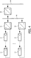
- FIG. 4 presents by way of example a PV power plant as a decentralize power generation system in which the invention may be implemented.
- An exemplary implementation of the invention in this PV power plant will be described with reference to figures 5 and 6 .
- the PV power plant of Figure 4 comprises a first series connection of PV modules 11, 12. Both ends of this first series connection are connected to the inputs of a first DC/DC converter 31.
- the PV power plant further comprises a second series connection of PV modules 13, 14. Both ends of this second series connection are connected to the inputs of a second DC/DC converter 32.
- the respective outputs of the DC/DC converters 31, 32 are connected to the lines of a common DC bus 40.
- Further PV modules can be connected in the same way via separate DC/DC converters to the DC bus 40.
- the PV power plant finally comprises an inverter 20.
- the inputs of the inverter 20 are equally connected to the lines of the DC bus 40, while the outputs of the inverter 20 are connected to lines 50 of a public power supply system.
- the PV-modules 11 to 14 produce a current depending on a respective intensity of illumination.
- the DC/DC converters 31, 32 survey the voltage provided by the respectively connected PV modules 11 to 14. As soon as a first predetermined voltage threshold is reached or exceeded by the voltage supplied by a specific series connection of PV modules 11 to 14, the associated DC/DC converter 31, 32 carries out a voltage conversion. Using the conventional MPP tracking, the input current to this DC/DC converter 31, 32 is set such that the connected PV modules 11 to 14 are operated in the bend of the characteristic curve, i.e. in the MPP. The MPP tracking is thus performed separately for each series connection of PV modules 11 to 14.
- the output power of the DC/DC converters 31, 32 is supplied to the DC bus 40.
- Two requirements determine the amount of power which each DC/DC converter 31, 32 is allowed to supply to the DC bus 40.
- the output voltage of the DC/DC converters 31, 32 is set to a predetermined bus voltage, which is the same for each DC/DC converter 31, 32 of the entire PV power plant.
- the current provided by a DC/DC converter 31, 32 is not allowed to exceed a predetermined maximum value. This maximum value can be different for each DC/DC converter 31, 32 and should be selected depending on the maximum power of the respectively connected PV modules 11 to 14.
- a DC/DC converter 31, 32 supplies energy to the DC bus 40 only if its output current is below a current threshold predetermined for this DC/DC converter 31, 32 and if the supply of energy does not increase the voltage on the DC bus 40 above the predetermined bus voltage as second predetermined voltage threshold.
- the inverter 20 which is connected to the DC bus 40, recognizes that at least one of the DC/DC converters 31, 32 is operating, if the predetermined bus voltage is available on the DC bus 40. If the predetermined bus voltage is available on the DC bus 40 and if a surveillance of the voltage on the lines 50 of the public power supply system currently allows such a supply, the inverter 20 may convert current retrieved from the DC bus 40 into an alternating current having a required frequency and a required code phase, and feed this alternating current into the lines 50 of the public power supply system.
- the inverter 20 thus learns indirectly via the voltage on the DC bus 40 that the energy supplied to the public power supply system is too high compared to the energy generated in the PV modules 11 to 14 and that the supply has to be reduced. When the inverter 20 reaches its maximum supply power before the voltage on the DC bus 40 drops, no problem will occur, since the DC/DC converters 31, 32 are not enabled to increase the voltage on the DC bus 40.
- the DC/DC converters 31, 32 can be controlled independently from each other and at the same time, long high direct current paths between the power generating units 11 to 14 and the DC/DC converters 31, 32 are avoided.
- FIG. 5 is a block diagram of a part of the PV power plant of Figure 4 including the inverter 20, the DC bus 40, one representative DC/DC converter 31 and one representative series connection of PV modules 11, 12.
- the series of PV modules 11, 12 is connected via the DC/DC converter 31, the DC bus 40 and the inverter 20 to the lines 50 of a public power supply system, just as in Figure 4 .
- the DC/DC converter 31 is shown to comprise in more detail a converting component 310 and a control component 311.
- the inputs of the DC/DC converter 31 are connected to inputs of the converting component 310, while outputs of the converting component 310 are connected to the outputs of the DC/DC converter 31.
- the control component 310 is arranged to monitor the voltage across the inputs of the converting component 310 and to monitor the voltage across the outputs of the converting component 310.
- the DC/DC converter 31 is connected to the DC bus 40 via a plug 71.
- the plug 70 comprises on the side of the DC/DC converter 31 a short-circuit switch 71, for instance a crowbar, for connecting the two output lines of the DC/DC converter 31.
- the short-circuit switch 71 is constructed and arranged such that it automatically disconnects the two output lines of the DC/DC converter 31 when the plug 70 is connected and that it automatically connects the two output lines of the DC/DC converter 31 when the plug 70 is disconnected.
- All other DC/DC converter 32 in the PV power plant not shown in Figure 5 is constructed and arranged in a corresponding manner.
- a further a short-circuit switch 72 for instance again a crowbar, is provided for short-circuiting the inputs of the inverter 20.
- the inverter 20 has a controlling access to the short-circuit switch 72.
- the short-circuit switch 72 is constructed and arranged such that it can be caused manually to connect and disconnect the inputs of the inverter 20, and moreover such that it can be caused in addition by the inverter 20 to connect and disconnect the inputs of the inverter 20.
- a central control unit 80 may have a corresponding controlling access to the short-circuit switch 72, as indicated in Figure 5 with dashed lines.
- Figure 6 is a flow chart illustrating specifically the operation in the DC/DC converter 31 of Figure 5 .
- the control component 311 of the DC/DC converter 31 monitors the voltage which is applied to the DC/DC converter 31 by connected PV modules 11 to 12. As soon as the first predetermined voltage threshold is reached or exceeded by the voltage supplied by the PV modules 11 to 12, the control component 311 causes the converting component 310 to carry out a DC/DC conversion, if the resulting current lies below the predetermined current threshold. The resulting current may be monitored as well by the control component 311. Using the conventional MPP tracking, the input current to the converting component 311 is set such that the connected PV modules 11 to 12 are operated in the MPP.
- the control component 311 further monitors the voltage at the output of the DC/DC converter 31, that is, the voltage on the DC bus 40. Only if the voltage on the DC bus 40 is smaller than or equal to the predetermined bus voltage as second voltage threshold, the process is continued.
- the control component 311 determines in addition whether the voltage on the DC bus 40 lies below a third predetermined voltage threshold which is smaller than the second predetermined voltage threshold, for example 85% of the second predetermined voltage threshold. If the control component 311 detects that the voltage on the DC bus 40 lies below this third predetermined voltage threshold, it causes the converting component 310 to enter a short-circuit protection mode.
- the converting component 310 repeatedly outputs the converted current, but only for a short duration at a time, while the control component 311 continues monitoring the voltage on the DC bus 40. If the voltage on the DC bus 40 does not raise above the third predetermined voltage threshold during a respective time period in which the converted current is output, the intermittent output of the converted current is continued.
- the short duration of time during which the current is output is selected such that as soon as the short-circuit is removed in the PV power plant, the current is able in one or several cycles to charge an input capacity (not shown) of the inverter 20 to a voltage lying above the third predetermined voltage threshold.
- the converting component 310 outputs a current which is limited to a not dangerous maximum value, while the control component 311 continues monitoring the voltage on the DC bus 40. As soon as the control component 311 determines that the voltage on the DC bus 40 lies above the third predetermined voltage threshold, which indicates that the short-circuit in the PV power plant has been removed, the control component 311 allows the converting component 310 to output the entire converted current.
- Both short-circuit protection mode alternatives are designed such that the PV power plant is not endangered by exceedingly high currents during a short-circuit on the DC bus 40 and that service personnel trying to remove the short-circuit is not exposed to danger.
- the DC/DC converter 31 is further designed such that after the short-circuit has been removed in the PV power plant, it will automatically continue with the regular operation.
- the PV power plant starts operating as soon as the extend of illumination of the PV modules 11, 12 is sufficient. At such a start, the voltage on the DC bus 40 will not reach the third predetermined voltage threshold immediately. With both short-circuit protection mode alternatives, it is ensured that the PV power plant does not remain tracked in a presumed short-circuit on the DC bus 40.
- the proposed construction of the DC/DC converter 31 can also be made use already when mounting the PV power plant of Figure 5 by creating an artificial short-circuit situation by means of the short-circuit switches 71, 72.
- the short-circuit switch 72 associated to the inverter 20 is closed.
- the short-circuit switch 71 in the plug 70 associated to the DC/DC converter 31 is closed automatically, as long as the plug 70 is disconnected.
- the PV power plant can then be mounted without danger to the mounting personnel, since no current will be provided to the DC bus 40 as long as the voltage at the output of the DC/DC converter 31 cannot reach the third predetermined voltage threshold due to the artificial short-circuits. Due to the construction of the DC/DC converter 31 according to the invention, the short-circuits do not endanger the PV modules 11, 12 or the DC/DC converters 31 either.
- the short-circuit switch 71 is opened automatically.
- the mounting personnel opens manually the short-circuit switch 72 associated to the inverter 20. Only when the last short-circuit switch 72 has been opened, the PV power plant can start to operate.
- the operation of a particular DC/DC converter 31 of the PV power plant can be interrupted again thereafter by opening the plug 70 connecting the DC/DC converter 31 to the DC bus 40, since this causes an automatic closing of the short-circuit switch 71 in the plug 70.
- the operation of the PV power plant as a whole can be interrupted by manually closing the short-circuit switch 72. Such intentionally caused interruptions may be useful for maintenance purposes or for an enlargement of the PV power plant.
- the operation of the entire PV power plant can moreover be interrupted automatically by the inverter 20 or by a central control unit 80 in case of detected failures in the PV power plant. This approach allows to protect the PV power plant for example from insulation burning.
- the PV power plant might not include fixedly installed short-circuit switches 71, 72.
- the output of each DC/DC converter 31 and/or the input of the inverter 20 may be short-circuited manually by short-circuit bridges before mounting of the PV power plant. When the mounting has been completed, the short-circuit bridges are then simply removed.
Landscapes
- Engineering & Computer Science (AREA)
- Power Engineering (AREA)
- Inverter Devices (AREA)
- Dc-Dc Converters (AREA)
Claims (5)
- Système décentralisé de génération d'énergie électrique, comprenant :- au moins une unité de génération d'énergie électrique pour générer un courant continu ;- un bus CC (40) pour rendre un courant fourni disponible à un composant de réception d'énergie électrique ; et- au moins un convertisseur CC/CC (31) connecté entre ladite au moins une unité de génération d'énergie électrique et ledit bus CC, ledit convertisseur CC/CC incluant un composant de conversion (310) pour réaliser une conversion CC/CC d'un courant continu fourni par ladite au moins une unité de génération d'énergie électrique et pour fournir un courant continu converti résultant audit bus CC, et ledit convertisseur CC/CC incluant en outre un composant de commande (311) agencé pour surveiller une tension aux sorties dudit convertisseur CC/CC,caractérisé en ce que ledit composant de commande est en outre agencé pour faire en sorte que ledit composant de conversion entre dans un mode de protection contre les courts-circuits si ladite tension surveillée est inférieure à un seuil de tension prédéterminé, comprenant en outre un composant de court-circuitage central (71) pour générer un court-circuit sur ledit bus CC et un composant de réception d'énergie électrique connecté audit bus CC et adapté pour faire en sorte que ledit composant de court-circuitage central génère automatiquement un court-circuit sur ledit bus CC en cas de situation de défaillance détectée dans ledit système décentralisé de génération d'énergie électrique.
- Système décentralisé de génération d'énergie électrique selon la revendication 1, comprenant en outre au moins une connexion à fiche pour connecter ledit au moins un convertisseur CC/CC audit bus CC, laquelle connexion à fiche comprend un composant de court-circuitage court-circuitant les sorties dudit convertisseur CC/CC automatiquement lorsque ladite connexion à fiche est ouverte et/ou éliminant un court-circuit entre les sorties dudit convertisseur CC/CC automatiquement lorsque ladite connexion à fiche est fermée.
- Système décentralisé de génération d'énergie électrique selon la revendication 1, dans lequel ledit composant de commande est en outre agencé pour faire en sorte que ledit composant de conversion sorte, à nouveau, d'un mode de protection contre les courts-circuits, dans lequel il est entré, si ladite tension surveillée devient supérieure audit seuil de tension prédéterminé.
- Système décentralisé de génération d'énergie électrique selon la revendication 1, dans lequel ledit composant de conversion est adapté pour produire en sortie un courant continu converti à plusieurs reprises seulement pendant une courte durée à la fois dans ledit mode de protection contre les courts-circuits.
- Système décentralisé de génération d'énergie électrique selon la revendication 1, dans lequel ledit composant de conversion est adapté pour produire en sortie un courant limité à une valeur maximum prédéterminée dans ledit mode de protection contre les courts-circuits.
Priority Applications (1)
| Application Number | Priority Date | Filing Date | Title |
|---|---|---|---|
| EP04806614.6A EP1706937B1 (fr) | 2004-01-09 | 2004-12-22 | Convertisseur continu-continu et système de production d'énergie décentralisé comprenant un convertisseur continu-continu |
Applications Claiming Priority (3)
| Application Number | Priority Date | Filing Date | Title |
|---|---|---|---|
| EP04100050 | 2004-01-09 | ||
| EP04806614.6A EP1706937B1 (fr) | 2004-01-09 | 2004-12-22 | Convertisseur continu-continu et système de production d'énergie décentralisé comprenant un convertisseur continu-continu |
| PCT/IB2004/052888 WO2005076444A1 (fr) | 2004-01-09 | 2004-12-22 | Convertisseur continu-continu et systeme de production d'energie decentralise comprenant un convertisseur continu-continu |
Publications (2)
| Publication Number | Publication Date |
|---|---|
| EP1706937A1 EP1706937A1 (fr) | 2006-10-04 |
| EP1706937B1 true EP1706937B1 (fr) | 2017-03-08 |
Family
ID=34833712
Family Applications (1)
| Application Number | Title | Priority Date | Filing Date |
|---|---|---|---|
| EP04806614.6A Active EP1706937B1 (fr) | 2004-01-09 | 2004-12-22 | Convertisseur continu-continu et système de production d'énergie décentralisé comprenant un convertisseur continu-continu |
Country Status (5)
| Country | Link |
|---|---|
| US (1) | US7443052B2 (fr) |
| EP (1) | EP1706937B1 (fr) |
| JP (1) | JP4846597B2 (fr) |
| CN (1) | CN100521471C (fr) |
| WO (1) | WO2005076444A1 (fr) |
Families Citing this family (100)
| Publication number | Priority date | Publication date | Assignee | Title |
|---|---|---|---|---|
| US11881814B2 (en) | 2005-12-05 | 2024-01-23 | Solaredge Technologies Ltd. | Testing of a photovoltaic panel |
| US10693415B2 (en) | 2007-12-05 | 2020-06-23 | Solaredge Technologies Ltd. | Testing of a photovoltaic panel |
| DE202006009906U1 (de) * | 2006-06-22 | 2006-10-05 | Sma Technologie Ag | Vorrichtung zur Aufnahme einer Mehrzahl einzelner Wechselrichter |
| US11855231B2 (en) | 2006-12-06 | 2023-12-26 | Solaredge Technologies Ltd. | Distributed power harvesting systems using DC power sources |
| US9112379B2 (en) | 2006-12-06 | 2015-08-18 | Solaredge Technologies Ltd. | Pairing of components in a direct current distributed power generation system |
| US11728768B2 (en) | 2006-12-06 | 2023-08-15 | Solaredge Technologies Ltd. | Pairing of components in a direct current distributed power generation system |
| US11735910B2 (en) | 2006-12-06 | 2023-08-22 | Solaredge Technologies Ltd. | Distributed power system using direct current power sources |
| US11888387B2 (en) | 2006-12-06 | 2024-01-30 | Solaredge Technologies Ltd. | Safety mechanisms, wake up and shutdown methods in distributed power installations |
| US8384243B2 (en) | 2007-12-04 | 2013-02-26 | Solaredge Technologies Ltd. | Distributed power harvesting systems using DC power sources |
| US9088178B2 (en) | 2006-12-06 | 2015-07-21 | Solaredge Technologies Ltd | Distributed power harvesting systems using DC power sources |
| US8963369B2 (en) | 2007-12-04 | 2015-02-24 | Solaredge Technologies Ltd. | Distributed power harvesting systems using DC power sources |
| US8319483B2 (en) | 2007-08-06 | 2012-11-27 | Solaredge Technologies Ltd. | Digital average input current control in power converter |
| US8816535B2 (en) * | 2007-10-10 | 2014-08-26 | Solaredge Technologies, Ltd. | System and method for protection during inverter shutdown in distributed power installations |
| US8013472B2 (en) | 2006-12-06 | 2011-09-06 | Solaredge, Ltd. | Method for distributed power harvesting using DC power sources |
| US11296650B2 (en) | 2006-12-06 | 2022-04-05 | Solaredge Technologies Ltd. | System and method for protection during inverter shutdown in distributed power installations |
| US8947194B2 (en) | 2009-05-26 | 2015-02-03 | Solaredge Technologies Ltd. | Theft detection and prevention in a power generation system |
| US8618692B2 (en) | 2007-12-04 | 2013-12-31 | Solaredge Technologies Ltd. | Distributed power system using direct current power sources |
| US11309832B2 (en) | 2006-12-06 | 2022-04-19 | Solaredge Technologies Ltd. | Distributed power harvesting systems using DC power sources |
| US8319471B2 (en) | 2006-12-06 | 2012-11-27 | Solaredge, Ltd. | Battery power delivery module |
| US11569659B2 (en) | 2006-12-06 | 2023-01-31 | Solaredge Technologies Ltd. | Distributed power harvesting systems using DC power sources |
| US9130401B2 (en) | 2006-12-06 | 2015-09-08 | Solaredge Technologies Ltd. | Distributed power harvesting systems using DC power sources |
| US11687112B2 (en) | 2006-12-06 | 2023-06-27 | Solaredge Technologies Ltd. | Distributed power harvesting systems using DC power sources |
| WO2009073868A1 (fr) * | 2007-12-05 | 2009-06-11 | Solaredge, Ltd. | Mécanismes de sécurité, procédés d'éveil et d'arrêt dans des installations de puissance réparties |
| US8473250B2 (en) | 2006-12-06 | 2013-06-25 | Solaredge, Ltd. | Monitoring of distributed power harvesting systems using DC power sources |
| US9196770B2 (en) | 2007-03-27 | 2015-11-24 | Newdoll Enterprises Llc | Pole-mounted power generation systems, structures and processes |
| US7772716B2 (en) | 2007-03-27 | 2010-08-10 | Newdoll Enterprises Llc | Distributed maximum power point tracking system, structure and process |
| CA2737134C (fr) | 2007-10-15 | 2017-10-10 | Ampt, Llc | Systemes pour energie solaire hautement efficace |
| WO2009055474A1 (fr) | 2007-10-23 | 2009-04-30 | And, Llc | Systèmes d'alimentation à haute fiabilité et convertisseurs d'énergie solaire |
| EP2232690B1 (fr) | 2007-12-05 | 2016-08-31 | Solaredge Technologies Ltd. | Onduleurs connectés en parallèle |
| WO2009072075A2 (fr) | 2007-12-05 | 2009-06-11 | Solaredge Technologies Ltd. | Procédé de suivi de puissance d'un système photovoltaïque |
| US11264947B2 (en) | 2007-12-05 | 2022-03-01 | Solaredge Technologies Ltd. | Testing of a photovoltaic panel |
| EP2225778B1 (fr) | 2007-12-05 | 2019-06-26 | Solaredge Technologies Ltd. | Test d'un panneau photovoltaïque |
| US8049523B2 (en) | 2007-12-05 | 2011-11-01 | Solaredge Technologies Ltd. | Current sensing on a MOSFET |
| DE202008000440U1 (de) * | 2008-01-11 | 2008-04-03 | Sma Technologie Ag | Wechselrichter |
| EP2722979B1 (fr) | 2008-03-24 | 2022-11-30 | Solaredge Technologies Ltd. | Convertisseur à découpage avec circuit auxiliaire de commutation par courant nul |
| WO2009136358A1 (fr) | 2008-05-05 | 2009-11-12 | Solaredge Technologies Ltd. | Circuit combinateur de puissance de courant continu |
| WO2010002960A1 (fr) * | 2008-07-01 | 2010-01-07 | Satcon Technology Corporation | Microconvertisseur continu/continu photovoltaïque |
| US8378656B2 (en) * | 2008-09-19 | 2013-02-19 | General Electric Company | Quasi-AC, photovoltaic module for unfolder photovoltaic inverter |
| SG175717A1 (en) | 2009-04-17 | 2011-12-29 | Ampt Llc | Methods and apparatus for adaptive operation of solar power systems |
| US8476524B2 (en) | 2009-05-22 | 2013-07-02 | Solaredge Technologies Ltd. | Electrically isolated heat dissipating junction box |
| TWI382625B (zh) * | 2009-07-13 | 2013-01-11 | Asus Technology Pte Ltd | 具軟啟動功能直流-直流轉換器的啟動短路保護裝置與方法 |
| US9200818B2 (en) | 2009-08-14 | 2015-12-01 | Newdoll Enterprises Llc | Enhanced solar panels, liquid delivery systems and associated processes for solar energy systems |
| US20160065127A1 (en) | 2009-08-14 | 2016-03-03 | Newdoll Enterprises Llc | Enhanced solar panels, liquid delivery systems and associated processes for solar energy systems |
| CN102574166B (zh) | 2009-08-14 | 2015-06-10 | 纽道尔企业有限责任公司 | 增强的太阳能面板、流体传送系统和用于太阳能系统的相关过程 |
| WO2011049985A1 (fr) | 2009-10-19 | 2011-04-28 | Ampt, Llc | Topologie novatrice de convertisseur de chaîne de panneau solaire |
| US7990743B2 (en) * | 2009-10-20 | 2011-08-02 | General Electric Company | System and method for decreasing solar collector system losses |
| US7855906B2 (en) * | 2009-10-26 | 2010-12-21 | General Electric Company | DC bus voltage control for two stage solar converter |
| FR2951872B1 (fr) * | 2009-10-28 | 2012-03-02 | Ferraz Shawmut | Installation de production de courant electrique, a partir du rayonnement solaire et procede de mise en securite d'un batiment equipe d'une telle installation |
| US8710699B2 (en) | 2009-12-01 | 2014-04-29 | Solaredge Technologies Ltd. | Dual use photovoltaic system |
| CN101795052B (zh) * | 2009-12-25 | 2013-04-24 | 中国电力科学研究院 | 基于晶闸管的高压直流输电用换流阀阀模块 |
| US8766696B2 (en) | 2010-01-27 | 2014-07-01 | Solaredge Technologies Ltd. | Fast voltage level shifter circuit |
| US8050062B2 (en) * | 2010-02-24 | 2011-11-01 | General Electric Company | Method and system to allow for high DC source voltage with lower DC link voltage in a two stage power converter |
| CN101826741B (zh) * | 2010-03-11 | 2012-07-04 | 哈尔滨工业大学深圳研究生院 | 太阳能电池充电系统及控制方法 |
| JP5714972B2 (ja) | 2010-05-07 | 2015-05-07 | 株式会社半導体エネルギー研究所 | 光電変換装置 |
| US8618462B2 (en) | 2010-05-26 | 2013-12-31 | Semiconductor Energy Laboratory Co., Ltd. | Photoelectric transducer device having a rectifier is a second transistor with diode-connected and normally on |
| JP2012015491A (ja) | 2010-06-04 | 2012-01-19 | Semiconductor Energy Lab Co Ltd | 光電変換装置 |
| US10673229B2 (en) | 2010-11-09 | 2020-06-02 | Solaredge Technologies Ltd. | Arc detection and prevention in a power generation system |
| US10230310B2 (en) | 2016-04-05 | 2019-03-12 | Solaredge Technologies Ltd | Safety switch for photovoltaic systems |
| GB2485527B (en) | 2010-11-09 | 2012-12-19 | Solaredge Technologies Ltd | Arc detection and prevention in a power generation system |
| US10673222B2 (en) | 2010-11-09 | 2020-06-02 | Solaredge Technologies Ltd. | Arc detection and prevention in a power generation system |
| GB2486408A (en) | 2010-12-09 | 2012-06-20 | Solaredge Technologies Ltd | Disconnection of a string carrying direct current |
| GB2496140B (en) | 2011-11-01 | 2016-05-04 | Solarcity Corp | Photovoltaic power conditioning units |
| GB2483317B (en) | 2011-01-12 | 2012-08-22 | Solaredge Technologies Ltd | Serially connected inverters |
| GB2485423B (en) | 2011-01-18 | 2014-06-04 | Enecsys Ltd | Solar photovoltaic systems |
| US8410847B2 (en) * | 2011-05-09 | 2013-04-02 | Analog Devices, Inc. | Input common mode voltage compensation circuit |
| KR101906895B1 (ko) * | 2011-06-08 | 2018-10-11 | 엘에스산전 주식회사 | 태양광 전력 변환 장치 |
| FR2976745B1 (fr) * | 2011-06-15 | 2015-07-17 | Schneider Electric Ind Sas | Mecanisme de commande securise pour systeme photovoltaique distribue |
| AU2012299019B2 (en) * | 2011-08-22 | 2016-11-24 | Franklin Electric Company, Inc. | Power conversion system |
| US8570005B2 (en) | 2011-09-12 | 2013-10-29 | Solaredge Technologies Ltd. | Direct current link circuit |
| GB2496139B (en) | 2011-11-01 | 2016-05-04 | Solarcity Corp | Photovoltaic power conditioning units |
| GB2498365A (en) | 2012-01-11 | 2013-07-17 | Solaredge Technologies Ltd | Photovoltaic module |
| GB2498791A (en) | 2012-01-30 | 2013-07-31 | Solaredge Technologies Ltd | Photovoltaic panel circuitry |
| US9853565B2 (en) | 2012-01-30 | 2017-12-26 | Solaredge Technologies Ltd. | Maximized power in a photovoltaic distributed power system |
| GB2498790A (en) | 2012-01-30 | 2013-07-31 | Solaredge Technologies Ltd | Maximising power in a photovoltaic distributed power system |
| JP5788535B2 (ja) * | 2012-02-09 | 2015-09-30 | 株式会社日立製作所 | 分散型発電装置の制御装置および制御方法 |
| GB2499991A (en) | 2012-03-05 | 2013-09-11 | Solaredge Technologies Ltd | DC link circuit for photovoltaic array |
| EP2859650B1 (fr) | 2012-05-25 | 2017-02-15 | Solaredge Technologies Ltd. | Circuit pour sources interconnectées d'alimentation en courant continu |
| US10115841B2 (en) | 2012-06-04 | 2018-10-30 | Solaredge Technologies Ltd. | Integrated photovoltaic panel circuitry |
| US9548619B2 (en) | 2013-03-14 | 2017-01-17 | Solaredge Technologies Ltd. | Method and apparatus for storing and depleting energy |
| US9941813B2 (en) | 2013-03-14 | 2018-04-10 | Solaredge Technologies Ltd. | High frequency multi-level inverter |
| EP4318001A3 (fr) | 2013-03-15 | 2024-05-01 | Solaredge Technologies Ltd. | Mécanisme de dérivation |
| US9397497B2 (en) | 2013-03-15 | 2016-07-19 | Ampt, Llc | High efficiency interleaved solar power supply system |
| CN103457239B (zh) * | 2013-08-30 | 2016-01-20 | 深圳晶福源科技股份有限公司 | 高频不间断电源短路的保护方法 |
| JP6085544B2 (ja) * | 2013-09-19 | 2017-02-22 | 三菱重工業株式会社 | 電気自動車用急速充電設備、充電設備のエネルギーマネジメント方法および充電設備システム |
| DE102013223167A1 (de) * | 2013-11-14 | 2015-06-03 | Robert Bosch Gmbh | Fotovoltaiksystem und Verfahren zum Betreiben eines Fotovoltaiksystems |
| CN106170916A (zh) * | 2014-02-07 | 2016-11-30 | Abb 瑞士股份有限公司 | 具有平衡降压/升压变换器的不间断电源 |
| US9318974B2 (en) | 2014-03-26 | 2016-04-19 | Solaredge Technologies Ltd. | Multi-level inverter with flying capacitor topology |
| US10027277B2 (en) | 2015-03-25 | 2018-07-17 | Zyntony, Inc. | Short-string parallel-DC optimizer for photovoltaic systems |
| CN104753057B (zh) * | 2015-04-22 | 2016-10-05 | 哈尔滨工业大学 | 直流微电网中光伏发电单元运行模式无缝切换方法 |
| US10044190B2 (en) | 2015-04-30 | 2018-08-07 | Zyntony, Inc. | Distributed energy system with four conductor bipolar DC bus |
| US9912754B2 (en) * | 2015-05-01 | 2018-03-06 | GM Global Technology Operations LLC | Vehicular data isolation device |
| US20170077709A1 (en) * | 2015-09-15 | 2017-03-16 | Abb Technology Ltd. | Pv system having distributed dc-dc converters |
| CN107153212B (zh) | 2016-03-03 | 2023-07-28 | 太阳能安吉科技有限公司 | 用于映射发电设施的方法 |
| US11081608B2 (en) | 2016-03-03 | 2021-08-03 | Solaredge Technologies Ltd. | Apparatus and method for determining an order of power devices in power generation systems |
| US10599113B2 (en) | 2016-03-03 | 2020-03-24 | Solaredge Technologies Ltd. | Apparatus and method for determining an order of power devices in power generation systems |
| DE102016105930A1 (de) | 2016-03-31 | 2017-10-05 | Sma Solar Technology Ag | Solarmodul, Betriebsverfahren Für ein Solarmodul und Photovoltaikanlage |
| US11018623B2 (en) | 2016-04-05 | 2021-05-25 | Solaredge Technologies Ltd. | Safety switch for photovoltaic systems |
| US11177663B2 (en) | 2016-04-05 | 2021-11-16 | Solaredge Technologies Ltd. | Chain of power devices |
| US12057807B2 (en) | 2016-04-05 | 2024-08-06 | Solaredge Technologies Ltd. | Chain of power devices |
| CN111342483A (zh) * | 2018-12-18 | 2020-06-26 | 汉能移动能源控股集团有限公司 | 一种太阳能发电系统 |
Family Cites Families (17)
| Publication number | Priority date | Publication date | Assignee | Title |
|---|---|---|---|---|
| GB8926073D0 (en) * | 1989-11-17 | 1990-01-10 | Amp Gmbh | Shunting device for use in electrical connectors |
| DE4032569A1 (de) | 1990-10-13 | 1992-04-16 | Flachglas Solartechnik Gmbh | Netzgekoppelte photovoltaikanlage |
| JP3271730B2 (ja) * | 1994-04-28 | 2002-04-08 | キヤノン株式会社 | 発電システムの充電制御装置 |
| JPH0851772A (ja) * | 1994-08-09 | 1996-02-20 | Funai Electric Co Ltd | スイッチング電源の保護回路 |
| JP3258862B2 (ja) * | 1995-07-11 | 2002-02-18 | シャープ株式会社 | 太陽電池出力点検機能を有する連系インバータ |
| US5861738A (en) * | 1997-11-13 | 1999-01-19 | Hughes Electronics Corporation | DC to DC converter with a single-fault tolerant clamp |
| JP2000112545A (ja) * | 1998-09-30 | 2000-04-21 | Daihen Corp | 太陽光発電システム |
| DE19904561C1 (de) * | 1999-02-04 | 2000-08-24 | Rossendorf Forschzent | Verfahren und Schaltungsanordnung zur Maximum-Power-Point-Steuerung von Solargeneratoren |
| DE19919766A1 (de) | 1999-04-29 | 2000-11-02 | Sma Regelsysteme Gmbh | Wechselrichter für eine Photovoltaik-Anlage |
| FI109248B (fi) * | 1999-07-19 | 2002-06-14 | Nokia Corp | Teholähde ja tasasuuntaajan oikosulkuvirran rajoitusjärjestely |
| GB0003501D0 (en) * | 2000-02-15 | 2000-04-05 | Sgs Thomson Microelectronics | Voltage converter |
| JP2002092755A (ja) * | 2000-07-10 | 2002-03-29 | Canon Inc | 太陽光発電システムおよび太陽光発電システムの制御方法 |
| JP3655831B2 (ja) * | 2001-02-14 | 2005-06-02 | シャープ株式会社 | 昇圧ユニット、パワーコンディショナ、およびそれらを用いた太陽光発電システム |
| US6580593B2 (en) * | 2001-03-14 | 2003-06-17 | Power Integrations, Inc. | Method and apparatus for fault condition protection of a switched mode power supply |
| JP4734747B2 (ja) * | 2001-04-06 | 2011-07-27 | ミツミ電機株式会社 | 電流制限回路及び電源回路 |
| DE10136147B4 (de) * | 2001-07-25 | 2004-11-04 | Kolm, Hendrik, Dipl.-Ing. | Photovoltaischer Wechselstromerzeuger |
| JP3796460B2 (ja) * | 2002-03-28 | 2006-07-12 | シャープ株式会社 | 太陽光発電システム用パワーコンディショナ |
-
2004
- 2004-12-22 WO PCT/IB2004/052888 patent/WO2005076444A1/fr not_active Application Discontinuation
- 2004-12-22 CN CNB2004800400723A patent/CN100521471C/zh active Active
- 2004-12-22 US US10/585,369 patent/US7443052B2/en active Active
- 2004-12-22 JP JP2006548444A patent/JP4846597B2/ja active Active
- 2004-12-22 EP EP04806614.6A patent/EP1706937B1/fr active Active
Non-Patent Citations (1)
| Title |
|---|
| None * |
Also Published As
| Publication number | Publication date |
|---|---|
| EP1706937A1 (fr) | 2006-10-04 |
| US20070165347A1 (en) | 2007-07-19 |
| WO2005076444A1 (fr) | 2005-08-18 |
| JP2007518386A (ja) | 2007-07-05 |
| US7443052B2 (en) | 2008-10-28 |
| CN1902809A (zh) | 2007-01-24 |
| JP4846597B2 (ja) | 2011-12-28 |
| CN100521471C (zh) | 2009-07-29 |
Similar Documents
| Publication | Publication Date | Title |
|---|---|---|
| EP1706937B1 (fr) | Convertisseur continu-continu et système de production d'énergie décentralisé comprenant un convertisseur continu-continu | |
| JP4965265B2 (ja) | 分散型発電システム | |
| KR101097261B1 (ko) | 전력 저장 시스템 및 그 제어 방법 | |
| KR101097260B1 (ko) | 계통 연계형 전력 저장 시스템 및 전력 저장 시스템 제어 방법 | |
| EP0817350B1 (fr) | Système d'alimentation avec interconnexion de système | |
| KR101084214B1 (ko) | 계통 연계형 전력 저장 시스템 및 전력 저장 시스템 제어 방법 | |
| JP5903622B2 (ja) | 電力供給システムおよび充放電用パワーコンディショナ | |
| US8809669B2 (en) | Photovoltaic arrays, in part having switches for short-circuiting of modules | |
| KR102113868B1 (ko) | 계통연계형 태양광 발전 시스템 | |
| WO2011065375A1 (fr) | Appareil de conversion d'énergie, système de production d'électricité et procédé de commande de charge/décharge | |
| KR101793579B1 (ko) | 직류-교류 공통 모선형 하이브리드 전원 시스템 | |
| US9866023B2 (en) | Security concept for integrating a battery into an inverter | |
| JP2008099527A (ja) | 電力系統に接続された自家発電設備における蓄電池設備および蓄電池設備の運転方法 | |
| EP3442116B1 (fr) | Installation pour l'alimentation d'équipements auxiliaires dans des usines génératrices d'énergie électrique | |
| JP2017135889A (ja) | 電力変換装置、及び電力変換システム | |
| JP2017184362A (ja) | パワーコンディショナ、電力供給システム及び電流制御方法 | |
| JP4405654B2 (ja) | 電力変換装置および発電装置 | |
| JPH0951638A (ja) | 分散形電源装置 | |
| US11722003B2 (en) | Power converter and method for operating a power converter | |
| CN114503386A (zh) | 操作发电系统的方法和使用该方法的发电系统 | |
| JP2021040458A (ja) | 電力変換装置、系統連系システム | |
| CN117318160B (zh) | 光伏逆变供电控制系统、方法、装置及存储介质 | |
| US11916511B1 (en) | Solar-battery integrated DC system | |
| KR20240088486A (ko) | 광 발전 시스템 | |
| KR20240054105A (ko) | 광 발전 시스템 |
Legal Events
| Date | Code | Title | Description |
|---|---|---|---|
| PUAI | Public reference made under article 153(3) epc to a published international application that has entered the european phase |
Free format text: ORIGINAL CODE: 0009012 |
|
| 17P | Request for examination filed |
Effective date: 20060809 |
|
| AK | Designated contracting states |
Kind code of ref document: A1 Designated state(s): AT BE BG CH CY CZ DE DK EE ES FI FR GB GR HU IE IS IT LI LT LU MC NL PL PT RO SE SI SK TR |
|
| DAX | Request for extension of the european patent (deleted) | ||
| 17Q | First examination report despatched |
Effective date: 20100111 |
|
| RAP1 | Party data changed (applicant data changed or rights of an application transferred) |
Owner name: KONINKLIJKE PHILIPS N.V. Owner name: PHILIPS INTELLECTUAL PROPERTY & STANDARDS GMBH |
|
| GRAP | Despatch of communication of intention to grant a patent |
Free format text: ORIGINAL CODE: EPIDOSNIGR1 |
|
| RAP1 | Party data changed (applicant data changed or rights of an application transferred) |
Owner name: PHILIPS LIGHTING HOLDING B.V. |
|
| INTG | Intention to grant announced |
Effective date: 20161006 |
|
| RIN1 | Information on inventor provided before grant (corrected) |
Inventor name: LUERKENS, PETER Inventor name: WENDT, MATTHIAS |
|
| GRAS | Grant fee paid |
Free format text: ORIGINAL CODE: EPIDOSNIGR3 |
|
| GRAA | (expected) grant |
Free format text: ORIGINAL CODE: 0009210 |
|
| AK | Designated contracting states |
Kind code of ref document: B1 Designated state(s): AT BE BG CH CY CZ DE DK EE ES FI FR GB GR HU IE IS IT LI LT LU MC NL PL PT RO SE SI SK TR |
|
| REG | Reference to a national code |
Ref country code: GB Ref legal event code: FG4D |
|
| REG | Reference to a national code |
Ref country code: DE Ref legal event code: R081 Ref document number: 602004050885 Country of ref document: DE Owner name: SIGNIFY HOLDING B.V., NL Free format text: FORMER OWNERS: PHILIPS INTELLECTUAL PROPERTY & STANDARDS GMBH, 20099 HAMBURG, DE; KONINKLIJKE PHILIPS ELECTRONICS N.V., EINDHOVEN, NL |
|
| REG | Reference to a national code |
Ref country code: CH Ref legal event code: EP Ref country code: AT Ref legal event code: REF Ref document number: 874348 Country of ref document: AT Kind code of ref document: T Effective date: 20170315 |
|
| REG | Reference to a national code |
Ref country code: IE Ref legal event code: FG4D |
|
| REG | Reference to a national code |
Ref country code: DE Ref legal event code: R096 Ref document number: 602004050885 Country of ref document: DE |
|
| REG | Reference to a national code |
Ref country code: LT Ref legal event code: MG4D |
|
| REG | Reference to a national code |
Ref country code: NL Ref legal event code: MP Effective date: 20170308 |
|
| PG25 | Lapsed in a contracting state [announced via postgrant information from national office to epo] |
Ref country code: LT Free format text: LAPSE BECAUSE OF FAILURE TO SUBMIT A TRANSLATION OF THE DESCRIPTION OR TO PAY THE FEE WITHIN THE PRESCRIBED TIME-LIMIT Effective date: 20170308 Ref country code: FI Free format text: LAPSE BECAUSE OF FAILURE TO SUBMIT A TRANSLATION OF THE DESCRIPTION OR TO PAY THE FEE WITHIN THE PRESCRIBED TIME-LIMIT Effective date: 20170308 Ref country code: GR Free format text: LAPSE BECAUSE OF FAILURE TO SUBMIT A TRANSLATION OF THE DESCRIPTION OR TO PAY THE FEE WITHIN THE PRESCRIBED TIME-LIMIT Effective date: 20170609 |
|
| REG | Reference to a national code |
Ref country code: AT Ref legal event code: MK05 Ref document number: 874348 Country of ref document: AT Kind code of ref document: T Effective date: 20170308 |
|
| PG25 | Lapsed in a contracting state [announced via postgrant information from national office to epo] |
Ref country code: ES Free format text: LAPSE BECAUSE OF FAILURE TO SUBMIT A TRANSLATION OF THE DESCRIPTION OR TO PAY THE FEE WITHIN THE PRESCRIBED TIME-LIMIT Effective date: 20170308 Ref country code: SE Free format text: LAPSE BECAUSE OF FAILURE TO SUBMIT A TRANSLATION OF THE DESCRIPTION OR TO PAY THE FEE WITHIN THE PRESCRIBED TIME-LIMIT Effective date: 20170308 Ref country code: BG Free format text: LAPSE BECAUSE OF FAILURE TO SUBMIT A TRANSLATION OF THE DESCRIPTION OR TO PAY THE FEE WITHIN THE PRESCRIBED TIME-LIMIT Effective date: 20170608 |
|
| PG25 | Lapsed in a contracting state [announced via postgrant information from national office to epo] |
Ref country code: NL Free format text: LAPSE BECAUSE OF FAILURE TO SUBMIT A TRANSLATION OF THE DESCRIPTION OR TO PAY THE FEE WITHIN THE PRESCRIBED TIME-LIMIT Effective date: 20170308 |
|
| PG25 | Lapsed in a contracting state [announced via postgrant information from national office to epo] |
Ref country code: CZ Free format text: LAPSE BECAUSE OF FAILURE TO SUBMIT A TRANSLATION OF THE DESCRIPTION OR TO PAY THE FEE WITHIN THE PRESCRIBED TIME-LIMIT Effective date: 20170308 Ref country code: SK Free format text: LAPSE BECAUSE OF FAILURE TO SUBMIT A TRANSLATION OF THE DESCRIPTION OR TO PAY THE FEE WITHIN THE PRESCRIBED TIME-LIMIT Effective date: 20170308 Ref country code: EE Free format text: LAPSE BECAUSE OF FAILURE TO SUBMIT A TRANSLATION OF THE DESCRIPTION OR TO PAY THE FEE WITHIN THE PRESCRIBED TIME-LIMIT Effective date: 20170308 Ref country code: RO Free format text: LAPSE BECAUSE OF FAILURE TO SUBMIT A TRANSLATION OF THE DESCRIPTION OR TO PAY THE FEE WITHIN THE PRESCRIBED TIME-LIMIT Effective date: 20170308 Ref country code: IT Free format text: LAPSE BECAUSE OF FAILURE TO SUBMIT A TRANSLATION OF THE DESCRIPTION OR TO PAY THE FEE WITHIN THE PRESCRIBED TIME-LIMIT Effective date: 20170308 Ref country code: AT Free format text: LAPSE BECAUSE OF FAILURE TO SUBMIT A TRANSLATION OF THE DESCRIPTION OR TO PAY THE FEE WITHIN THE PRESCRIBED TIME-LIMIT Effective date: 20170308 |
|
| PG25 | Lapsed in a contracting state [announced via postgrant information from national office to epo] |
Ref country code: PT Free format text: LAPSE BECAUSE OF FAILURE TO SUBMIT A TRANSLATION OF THE DESCRIPTION OR TO PAY THE FEE WITHIN THE PRESCRIBED TIME-LIMIT Effective date: 20170710 Ref country code: PL Free format text: LAPSE BECAUSE OF FAILURE TO SUBMIT A TRANSLATION OF THE DESCRIPTION OR TO PAY THE FEE WITHIN THE PRESCRIBED TIME-LIMIT Effective date: 20170308 Ref country code: IS Free format text: LAPSE BECAUSE OF FAILURE TO SUBMIT A TRANSLATION OF THE DESCRIPTION OR TO PAY THE FEE WITHIN THE PRESCRIBED TIME-LIMIT Effective date: 20170708 |
|
| REG | Reference to a national code |
Ref country code: DE Ref legal event code: R097 Ref document number: 602004050885 Country of ref document: DE |
|
| REG | Reference to a national code |
Ref country code: FR Ref legal event code: PLFP Year of fee payment: 14 |
|
| PLBE | No opposition filed within time limit |
Free format text: ORIGINAL CODE: 0009261 |
|
| STAA | Information on the status of an ep patent application or granted ep patent |
Free format text: STATUS: NO OPPOSITION FILED WITHIN TIME LIMIT |
|
| PG25 | Lapsed in a contracting state [announced via postgrant information from national office to epo] |
Ref country code: DK Free format text: LAPSE BECAUSE OF FAILURE TO SUBMIT A TRANSLATION OF THE DESCRIPTION OR TO PAY THE FEE WITHIN THE PRESCRIBED TIME-LIMIT Effective date: 20170308 |
|
| 26N | No opposition filed |
Effective date: 20171211 |
|
| PG25 | Lapsed in a contracting state [announced via postgrant information from national office to epo] |
Ref country code: SI Free format text: LAPSE BECAUSE OF FAILURE TO SUBMIT A TRANSLATION OF THE DESCRIPTION OR TO PAY THE FEE WITHIN THE PRESCRIBED TIME-LIMIT Effective date: 20170308 |
|
| REG | Reference to a national code |
Ref country code: CH Ref legal event code: PL |
|
| REG | Reference to a national code |
Ref country code: IE Ref legal event code: MM4A |
|
| PG25 | Lapsed in a contracting state [announced via postgrant information from national office to epo] |
Ref country code: LU Free format text: LAPSE BECAUSE OF NON-PAYMENT OF DUE FEES Effective date: 20171222 |
|
| REG | Reference to a national code |
Ref country code: BE Ref legal event code: MM Effective date: 20171231 |
|
| PG25 | Lapsed in a contracting state [announced via postgrant information from national office to epo] |
Ref country code: IE Free format text: LAPSE BECAUSE OF NON-PAYMENT OF DUE FEES Effective date: 20171222 |
|
| PG25 | Lapsed in a contracting state [announced via postgrant information from national office to epo] |
Ref country code: LI Free format text: LAPSE BECAUSE OF NON-PAYMENT OF DUE FEES Effective date: 20171231 Ref country code: BE Free format text: LAPSE BECAUSE OF NON-PAYMENT OF DUE FEES Effective date: 20171231 Ref country code: CH Free format text: LAPSE BECAUSE OF NON-PAYMENT OF DUE FEES Effective date: 20171231 |
|
| PG25 | Lapsed in a contracting state [announced via postgrant information from national office to epo] |
Ref country code: HU Free format text: LAPSE BECAUSE OF FAILURE TO SUBMIT A TRANSLATION OF THE DESCRIPTION OR TO PAY THE FEE WITHIN THE PRESCRIBED TIME-LIMIT; INVALID AB INITIO Effective date: 20041222 Ref country code: MC Free format text: LAPSE BECAUSE OF FAILURE TO SUBMIT A TRANSLATION OF THE DESCRIPTION OR TO PAY THE FEE WITHIN THE PRESCRIBED TIME-LIMIT Effective date: 20170308 |
|
| PG25 | Lapsed in a contracting state [announced via postgrant information from national office to epo] |
Ref country code: CY Free format text: LAPSE BECAUSE OF NON-PAYMENT OF DUE FEES Effective date: 20170308 |
|
| PG25 | Lapsed in a contracting state [announced via postgrant information from national office to epo] |
Ref country code: TR Free format text: LAPSE BECAUSE OF FAILURE TO SUBMIT A TRANSLATION OF THE DESCRIPTION OR TO PAY THE FEE WITHIN THE PRESCRIBED TIME-LIMIT Effective date: 20170308 |
|
| REG | Reference to a national code |
Ref country code: DE Ref legal event code: R082 Ref document number: 602004050885 Country of ref document: DE Representative=s name: MEISSNER BOLTE PATENTANWAELTE RECHTSANWAELTE P, DE Ref country code: DE Ref legal event code: R081 Ref document number: 602004050885 Country of ref document: DE Owner name: SIGNIFY HOLDING B.V., NL Free format text: FORMER OWNER: PHILIPS LIGHTING HOLDING B.V., EINDHOVEN, NL |
|
| PGFP | Annual fee paid to national office [announced via postgrant information from national office to epo] |
Ref country code: GB Payment date: 20221220 Year of fee payment: 19 Ref country code: FR Payment date: 20221222 Year of fee payment: 19 |
|
| PGFP | Annual fee paid to national office [announced via postgrant information from national office to epo] |
Ref country code: DE Payment date: 20230224 Year of fee payment: 19 |
|
| P01 | Opt-out of the competence of the unified patent court (upc) registered |
Effective date: 20230421 |
|
| REG | Reference to a national code |
Ref country code: DE Ref legal event code: R119 Ref document number: 602004050885 Country of ref document: DE |
|
| GBPC | Gb: european patent ceased through non-payment of renewal fee |
Effective date: 20231222 |