EP1706017B1 - Appareil d'examen de l'oeil par tomographie avec dispositif de visee - Google Patents
Appareil d'examen de l'oeil par tomographie avec dispositif de visee Download PDFInfo
- Publication number
- EP1706017B1 EP1706017B1 EP05717462.5A EP05717462A EP1706017B1 EP 1706017 B1 EP1706017 B1 EP 1706017B1 EP 05717462 A EP05717462 A EP 05717462A EP 1706017 B1 EP1706017 B1 EP 1706017B1
- Authority
- EP
- European Patent Office
- Prior art keywords
- eye
- subject
- target
- examined
- sighting
- Prior art date
- Legal status (The legal status is an assumption and is not a legal conclusion. Google has not performed a legal analysis and makes no representation as to the accuracy of the status listed.)
- Expired - Lifetime
Links
- 238000003325 tomography Methods 0.000 title claims description 12
- 238000005259 measurement Methods 0.000 claims description 12
- 238000001727 in vivo Methods 0.000 claims description 11
- 230000003044 adaptive effect Effects 0.000 claims description 10
- 238000000034 method Methods 0.000 claims description 9
- 238000012937 correction Methods 0.000 claims description 7
- 238000001514 detection method Methods 0.000 claims description 7
- 230000001360 synchronised effect Effects 0.000 claims description 6
- 238000003384 imaging method Methods 0.000 claims description 5
- 230000003287 optical effect Effects 0.000 claims description 4
- 238000012014 optical coherence tomography Methods 0.000 claims 3
- 238000001429 visible spectrum Methods 0.000 claims 1
- 210000001525 retina Anatomy 0.000 description 8
- 210000001747 pupil Anatomy 0.000 description 5
- 206010065042 Immune reconstitution inflammatory syndrome Diseases 0.000 description 3
- 230000002207 retinal effect Effects 0.000 description 3
- 102100037086 Bone marrow stromal antigen 2 Human genes 0.000 description 2
- 101000740785 Homo sapiens Bone marrow stromal antigen 2 Proteins 0.000 description 2
- 206010044565 Tremor Diseases 0.000 description 2
- 230000004075 alteration Effects 0.000 description 2
- 230000000875 corresponding effect Effects 0.000 description 2
- 238000006073 displacement reaction Methods 0.000 description 2
- 230000004424 eye movement Effects 0.000 description 2
- 230000004459 microsaccades Effects 0.000 description 2
- 206010029864 nystagmus Diseases 0.000 description 2
- 238000005457 optimization Methods 0.000 description 2
- 230000010355 oscillation Effects 0.000 description 2
- 230000010287 polarization Effects 0.000 description 2
- 230000001179 pupillary effect Effects 0.000 description 2
- 230000001869 rapid Effects 0.000 description 2
- 238000005070 sampling Methods 0.000 description 2
- 238000001228 spectrum Methods 0.000 description 2
- 230000002123 temporal effect Effects 0.000 description 2
- 238000011144 upstream manufacturing Methods 0.000 description 2
- 208000003443 Unconsciousness Diseases 0.000 description 1
- 240000008042 Zea mays Species 0.000 description 1
- 201000009310 astigmatism Diseases 0.000 description 1
- 230000005540 biological transmission Effects 0.000 description 1
- 230000002596 correlated effect Effects 0.000 description 1
- 238000010586 diagram Methods 0.000 description 1
- 238000000605 extraction Methods 0.000 description 1
- 238000001914 filtration Methods 0.000 description 1
- 238000005286 illumination Methods 0.000 description 1
- 238000000691 measurement method Methods 0.000 description 1
- 238000012544 monitoring process Methods 0.000 description 1
- 230000007935 neutral effect Effects 0.000 description 1
- 230000000737 periodic effect Effects 0.000 description 1
- 238000012545 processing Methods 0.000 description 1
- 230000005855 radiation Effects 0.000 description 1
- 230000035945 sensitivity Effects 0.000 description 1
- 238000000926 separation method Methods 0.000 description 1
- 238000004513 sizing Methods 0.000 description 1
- 230000006641 stabilisation Effects 0.000 description 1
- 238000011105 stabilization Methods 0.000 description 1
- 230000003068 static effect Effects 0.000 description 1
- 230000008685 targeting Effects 0.000 description 1
- 238000012360 testing method Methods 0.000 description 1
- 238000012876 topography Methods 0.000 description 1
- 230000000007 visual effect Effects 0.000 description 1
- 238000012800 visualization Methods 0.000 description 1
Images

Classifications
-
- A—HUMAN NECESSITIES
- A61—MEDICAL OR VETERINARY SCIENCE; HYGIENE
- A61B—DIAGNOSIS; SURGERY; IDENTIFICATION
- A61B3/00—Apparatus for testing the eyes; Instruments for examining the eyes
- A61B3/0091—Fixation targets for viewing direction
Definitions
- the present invention relates to a sighting device for an examination of the eye. It also relates to a targeting method implemented in this device, as well as an in vivo tomography eye examination system equipped with this device.
- the device US 3,836,238 is disclosed in combination with an aberrometer, while the device of US 5,565,949 is intended to perform field of view measurements.
- the object of the present invention is to overcome these drawbacks by proposing a sighting device that optimizes the fixing performance of the subject, the aiming device being intended to equip an examination system by providing a very good spatial resolution. It is therefore a question of increasing the overall performance of the examination by increasing that of the subject.
- the aiming device comprises at least one moving target having a shape and a programmable trajectory, this or these targets being displayed on viewing means such as a screen and visible from both eyes during the examination.
- the target or targets are moved so as to alternate fixing intervals at a given position with so-called rest intervals on one or more other positions.
- the duration of the fixing intervals can be adjusted to optimize the quality. It is also possible to adjust the diversity, the position and the duration of the rest positions.
- a continuous movement is controlled which forces the subject's gaze to follow a moving target. If the tracking performance is better than that of fixation, a priori knowledge of the trajectory would make it possible to reset the images of the eye obtained with a better precision than they are when one observes a still target.
- This sighting device makes it possible to guide the patient's gaze while ensuring his visual comfort and optimizing his fixing performance.
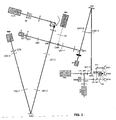
- This system comprises a Michelson type interferometer, comprising a measuring arm intended to illuminate the eye and to collect the reflected light, and a reference arm intended to illuminate a mobile mirror allowing the deep exploration of the retinal tissue.
- the interferometer is used in rectilinear and perpendicularly polarized light in both arms.
- the light source S is a diode with a small temporal coherence length (for example, 12 ⁇ m) whose spectrum is centered on 780 nm. It gives in principle to the in vivo tomography system an axial resolution equal to half the coherence length divided by the refractive index of the medium.
- This light source S can be pulsed. In this case, it is then synchronized with image capture and adaptive correction.
- the beam is limited by a field diaphragm corresponding to 1 degree in the field of view of the eye (300 ⁇ m on the retina) and a pupillary diaphragm corresponding to an opening of 7 mm on a dilated eye.
- An input polarizer P allows optimal balancing flows injected into the two arms of the interferometer.
- the two arms have a configuration called Gauss, afocal, which allows the transport of the pupils, on the one hand, and the materialization of an intermediate image of the field where a diaphragm blocks a large part of the corneal reflection, on the other hand.
- Quarter-wave plates provide by rotation of the polarization of the only light reflected by the eye, and the movable mirror, effective filtering parasitized reflections in the in vivo tomography system according to the invention.
- the reference arm is similar to the measuring arm, but with static optics.
- the detection path of the in vivo tomography system according to the invention will now be described.
- the two beams on the output arm are still polarized perpendicularly, and they interfer only if they are projected on a common direction.
- a prism of Wollaston W has the function of simultaneously projecting the two radiations on two perpendicular directions of analysis. It is then possible to perform a simultaneous measurement of the intensity after interference in two opposing interference states, without modulation or synchronous detection, on a single two-dimensional detector.
- the addition of a quarter wave plate, after division of the beam allows access to two additional measurements, thus removing any ambiguity between amplitude and phase of the fringes.
- a half-wave plate at the entrance of the detection channel makes it possible to correctly orient the incident polarizations.
- the Wollaston prism is placed in a pupillary plane, thus conjugated with the separator cube of the Michelson interferometer.
- the angle of separation of the Wollaston prism is chosen according to the field to be observed.
- the focal length of the final lens determines the sampling rate of the four images.
- the detector is of the CCD type, with an image rate of more than 30 frames per second.
- This detector is associated with a dedicated computer (not shown) in which digital image processing is performed: extraction of the four measurements, calibration, calculation of the amplitude of the fringes.
- the adaptive correction of the wave fronts is performed upstream of the interferometer, thus in the measuring arm.
- Each point of the source S thus sees its image on the corrected retina of the aberrations, and the image in return is also corrected.
- the amplitude of the fringes is then maximum.
- the adaptive optics subsystem includes a deformable mirror MD.
- the wavefront measurement is made by a Shack-Hartmann SH analyzer on the return beam of a light spot itself imaged on the retina via the deformable mirror MD.
- the wavelength analysis is 820 nm.
- the illumination is continuous and provided by a temporally incoherent superluminescent SLD diode.
- the sizing of the analyzer corresponds to an optimization between photometric sensitivity and sampling of the wavefront.
- the rate of refreshing of the control of the deformable mirror MD can reach 150 Hz.
- a dedicated computer (not shown) manages the adaptive optics loop. The control is however synchronized to freeze the mirror shape during the interferometric measurement.
- An appropriate control of the focusing of the analysis channel, by means of a lens LA2, makes it possible to adapt the focusing distance to the layer selected by the interferometer. This arrangement is essential to maintain optimal contrast at any depth.
- the deformable mirror MD is conjugated with the pupil of the system and the eye.
- the system field is defined by the system input DCM field iris. It is preferably chosen at a value lower than that of the isoplanetism field of the eye, which guarantees the validity of the adaptive correction in the field on the only wavefront measurement made from the spot, in the center of the field.
- the field of the system can be chosen equal to 1 degree, but the value of this field could be increased.
- the rotation of the deformable mirror MD makes it possible to choose the angle of arrival of the beam in the eye, and thus the portion of retina studied.
- a transmission adaptive corrector system may be used in preference to fixed lenses for optimal correction.
- the system may further comprise conventional imaging means, such as an IMG camera, for associating the interferometric measurements with a simple imaging of the areas examined, for example to facilitate the exploration and selection of the areas to be examined.
- conventional imaging means such as an IMG camera
- a second polarizing cube CNPI places directly at the output (at the return) of the measuring arm, thus just before the CPR polarizer cube of the interferometer, a second polarizing cube CNPI makes it possible to divert the return beam towards an IMG imaging camera having its own means of LI focus of the image. On this path, a direct image of the targeted retinal area will be observable.
- the measuring arm and this additional channel so that they provide a wider field of observation than the interferometric mode, the field of which is limited in particular by the interferometric contrast measurement technique itself.
- a sighting device collaborative or active, is installed upstream of the assembly.
- This aiming system which includes an active MAM pattern, presents to the subject the image of a light point that departs periodically from the desired line of sight. The patient is then invited to follow all the movements of this image. Whenever the image returns to the axis, and after an adjustable latency, a series of interferometric measurements is performed. The periodic displacement of the gaze makes it possible to obtain from the patient a better fixation capacity when he aims at the desired axis. The amplitude and the frequency are adaptable to the subject and the measures undertaken. For the sake of convenience, the test pattern can be performed with a simple desktop computer on which a bright spot is displayed and moved.
- the active MAM pattern, adaptive optics, S source, and image capture are synchronized.
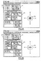
- a graphical user interface IA or IB comprises, for example, a first window F1 for managing a spot, a second window F2 for continuous shooting, and a moving target CA or CB on a zone of the screen.
- This moving target can be realized for example in the form of a conventional representation target consisting of a set of concentric circles and a cross of sight in the center of these circles ( Figure 2A ), or in the form of a graduated cursor and a superimposed cross Figure 2B )
- the system is arranged so that the target of the active MAM pattern is visible by the two eyes OD1 and OG1 of the subject to be examined.
- a sight with both eyes can indeed improve the performance of fixations or stability, and facilitate the examination.
- the image of the pattern is introduced into the optical path between the reference source SLD and the eye examined by a separator BST3.
- This separator can be chosen dichroic so as to reflect 50% of all the light coming from the MAM pattern toward the examined OEX eye, and transmit the remaining 50% to the other eye OV1 or OV2 to allow a sighting of both eyes.
- the dichroic splitter BST3 then transmits all of the light from the SLD reference source to the examined OEX eye, taking advantage of a spectrum difference between the SLD reference source (830 nm) and the MAM pattern (800 nm).
- a 50/50 fully spectrally neutral splitter plate is also suitable, but 50% of the SLD light is sent to the un-studied eye.
- a filter can eliminate this image if it is considered troublesome by the subject.
- the system In order to be able to examine any of the two eyes while providing sighting for both eyes, the system has a central OEX examination location, as well as two OV1 and OV2 sighting locations on both sides of this location. OEX exam.
- the right eye When the left eye is in the central location to be examined, the right eye receives the image of the MAM pattern in its sighting location OV1 by retractable return means, for example two mirrors MT1 and MT2.
- retractable return means for example two mirrors MT1 and MT2.
- the deflection means may be retracted or canceled and the image of the MAM pattern reaches the left eye in its OV2 sighting location.
- the system may also include, or collaborate with, IRIS tracking means of the movements of the eye to be examined, collaborating with the tomography device. It may be for example a camera with image recognition performing tracking or "tracking", for example of the retina or pupil or edges of the iris, so as to detect and evaluate the movements of the 'eye.
- Knowing the movements of the eye then allows the system to adapt to the movements of the area to be examined, for example by coordinating and setting and shooting with the different detected or predicted positions of this area to be examined, or by allowing a spatial and / or temporal optimization of the adaptive optics. It is possible for example to take advantage of the natural periods of stabilization of the pupil or the retina to achieve all or part of the adjustments or desired measurements.
- the image of the examined eye reaches the IRIS eye tracking means by a separator BST2 inserted in the optical path, for example between the eye and the reference source SLD.
- this separator BST2 is dichroic and the monitoring of the movements of the eye is in non-visible light, for example infrared.
- the IRIS tracking means may comprise for example a device for measuring eye movements, such as those developed by the company Mperivision.
- the invention may in particular be implemented to make or complete a retinal imaging device, or corneal topography, or measuring a film of tears.
Landscapes
- Life Sciences & Earth Sciences (AREA)
- Health & Medical Sciences (AREA)
- Medical Informatics (AREA)
- Biophysics (AREA)
- Ophthalmology & Optometry (AREA)
- Engineering & Computer Science (AREA)
- Biomedical Technology (AREA)
- Heart & Thoracic Surgery (AREA)
- Physics & Mathematics (AREA)
- Molecular Biology (AREA)
- Surgery (AREA)
- Animal Behavior & Ethology (AREA)
- General Health & Medical Sciences (AREA)
- Public Health (AREA)
- Veterinary Medicine (AREA)
- Eye Examination Apparatus (AREA)
- Medicines Containing Antibodies Or Antigens For Use As Internal Diagnostic Agents (AREA)
Applications Claiming Priority (2)
| Application Number | Priority Date | Filing Date | Title |
|---|---|---|---|
| FR0400581A FR2865371B1 (fr) | 2004-01-22 | 2004-01-22 | Dispositif et procede de visee pour un examen de l'oeil, systeme d'examen de l'oeil par tomographie in vivo equipe de ce dispositif |
| PCT/FR2005/000133 WO2005079655A1 (fr) | 2004-01-22 | 2005-01-21 | Appareil d’examen de l’oeil par tomographe avec dispositif de visee |
Publications (2)
| Publication Number | Publication Date |
|---|---|
| EP1706017A1 EP1706017A1 (fr) | 2006-10-04 |
| EP1706017B1 true EP1706017B1 (fr) | 2013-11-27 |
Family
ID=34717341
Family Applications (1)
| Application Number | Title | Priority Date | Filing Date |
|---|---|---|---|
| EP05717462.5A Expired - Lifetime EP1706017B1 (fr) | 2004-01-22 | 2005-01-21 | Appareil d'examen de l'oeil par tomographie avec dispositif de visee |
Country Status (6)
| Country | Link |
|---|---|
| US (2) | US7438415B2 (enExample) |
| EP (1) | EP1706017B1 (enExample) |
| JP (1) | JP2007518505A (enExample) |
| CA (1) | CA2553741C (enExample) |
| FR (1) | FR2865371B1 (enExample) |
| WO (1) | WO2005079655A1 (enExample) |
Families Citing this family (23)
| Publication number | Priority date | Publication date | Assignee | Title |
|---|---|---|---|---|
| GB2429522A (en) | 2005-08-26 | 2007-02-28 | Univ Kent Canterbury | Optical mapping apparatus |
| US7400410B2 (en) * | 2005-10-05 | 2008-07-15 | Carl Zeiss Meditec, Inc. | Optical coherence tomography for eye-length measurement |
| JP4822332B2 (ja) * | 2006-06-22 | 2011-11-24 | 株式会社トプコン | 眼科装置 |
| JP4822331B2 (ja) * | 2006-06-22 | 2011-11-24 | 株式会社トプコン | 眼科装置 |
| ATE492203T1 (de) * | 2006-11-02 | 2011-01-15 | Heidelberg Engineering Gmbh | Verfahren und gerät zur netzhautdiagnostik |
| US8016420B2 (en) | 2007-05-17 | 2011-09-13 | Amo Development Llc. | System and method for illumination and fixation with ophthalmic diagnostic instruments |
| US8348429B2 (en) | 2008-03-27 | 2013-01-08 | Doheny Eye Institute | Optical coherence tomography device, method, and system |
| WO2010009447A2 (en) | 2008-07-18 | 2010-01-21 | Doheny Eye Institute | Optical coherence tomography - based ophthalmic testing methods, devices and systems |
| US11839430B2 (en) | 2008-03-27 | 2023-12-12 | Doheny Eye Institute | Optical coherence tomography-based ophthalmic testing methods, devices and systems |
| WO2010117386A1 (en) * | 2009-04-10 | 2010-10-14 | Doheny Eye Institute | Ophthalmic testing methods, devices and systems |
| US10772497B2 (en) | 2014-09-12 | 2020-09-15 | Envision Diagnostics, Inc. | Medical interfaces and other medical devices, systems, and methods for performing eye exams |
| US9226856B2 (en) | 2013-03-14 | 2016-01-05 | Envision Diagnostics, Inc. | Inflatable medical interfaces and other medical devices, systems, and methods |
| US9424572B2 (en) | 2014-03-04 | 2016-08-23 | Bank Of America Corporation | Online banking digital wallet management |
| EP3349642B1 (en) | 2015-09-17 | 2020-10-21 | Envision Diagnostics, Inc. | Medical interfaces and other medical devices, systems, and methods for performing eye exams |
| WO2017174998A1 (en) | 2016-04-06 | 2017-10-12 | The University Court Of The University Of Edinburgh | Endoscopic imaging apparatus and method |
| WO2017190087A1 (en) | 2016-04-30 | 2017-11-02 | Envision Diagnostics, Inc. | Medical devices, systems, and methods for performing eye exams and eye tracking |
| GB201707239D0 (en) | 2017-05-05 | 2017-06-21 | Univ Edinburgh | Optical system and method |
| US10524165B2 (en) | 2017-06-22 | 2019-12-31 | Bank Of America Corporation | Dynamic utilization of alternative resources based on token association |
| US10511692B2 (en) | 2017-06-22 | 2019-12-17 | Bank Of America Corporation | Data transmission to a networked resource based on contextual information |
| US10313480B2 (en) | 2017-06-22 | 2019-06-04 | Bank Of America Corporation | Data transmission between networked resources |
| EP3572765A1 (de) * | 2018-05-23 | 2019-11-27 | Haag-Streit Ag | Oct-system und oct-verfahren |
| CN108433699B (zh) * | 2018-06-07 | 2024-07-12 | 杭州瞳创医疗科技有限公司 | 一种双眼眼底照相机设备 |
| FR3100703B1 (fr) * | 2019-09-13 | 2025-04-25 | E Swin Dev | Dispositif et procede de detection de rupture de film lacrymal |
Family Cites Families (12)
| Publication number | Priority date | Publication date | Assignee | Title |
|---|---|---|---|---|
| US3836238A (en) * | 1973-05-09 | 1974-09-17 | Tropel | Viewable target system for eye examining instrument |
| GB2031607B (en) * | 1978-09-12 | 1983-05-25 | Crick J | Apparatus for detecting visual field defects of the eye |
| US4995717A (en) * | 1989-08-22 | 1991-02-26 | The University Court Of The University Of Glasgow | Device for moving eye campimetry |
| US5565949A (en) * | 1995-07-10 | 1996-10-15 | Kasha, Jr.; John R. | Visual field perimetry on a small computer screen |
| US6271914B1 (en) * | 1996-11-25 | 2001-08-07 | Autonomous Technologies Corporation | Objective measurement and correction of optical systems using wavefront analysis |
| US5777719A (en) * | 1996-12-23 | 1998-07-07 | University Of Rochester | Method and apparatus for improving vision and the resolution of retinal images |
| CA2311818C (en) * | 1997-11-21 | 2002-10-01 | Autonomous Technologies Corporation | Objective measurement and correction of optical systems using wavefront analysis |
| FR2791548B1 (fr) * | 1999-04-01 | 2001-07-06 | Univ Paris Vii Denis Diderot | Dispositif d'observation d'un corps a haute resolution |
| ATE508676T1 (de) * | 2001-03-15 | 2011-05-15 | Amo Wavefront Sciences Llc | Topografisches wellenfrontanalysesystem und abbildungsverfahren für ein optisches system |
| JP4157839B2 (ja) | 2001-08-30 | 2008-10-01 | ユニバーシティー オブ ロチェスター | 生体眼の網膜領域撮像方法及びそのシステム |
| US7006232B2 (en) * | 2002-04-05 | 2006-02-28 | Case Western Reserve University | Phase-referenced doppler optical coherence tomography |
| AU2003245458A1 (en) | 2002-06-12 | 2003-12-31 | Advanced Research And Technology Institute, Inc. | Method and apparatus for improving both lateral and axial resolution in ophthalmoscopy |
-
2004
- 2004-01-22 FR FR0400581A patent/FR2865371B1/fr not_active Expired - Fee Related
-
2005
- 2005-01-21 US US10/586,839 patent/US7438415B2/en not_active Expired - Fee Related
- 2005-01-21 WO PCT/FR2005/000133 patent/WO2005079655A1/fr not_active Ceased
- 2005-01-21 EP EP05717462.5A patent/EP1706017B1/fr not_active Expired - Lifetime
- 2005-01-21 CA CA2553741A patent/CA2553741C/en not_active Expired - Fee Related
- 2005-01-21 JP JP2006550237A patent/JP2007518505A/ja active Pending
-
2008
- 2008-09-12 US US12/210,058 patent/US7658495B2/en not_active Expired - Fee Related
Also Published As
| Publication number | Publication date |
|---|---|
| US20090002630A1 (en) | 2009-01-01 |
| FR2865371B1 (fr) | 2007-12-21 |
| US20070177104A1 (en) | 2007-08-02 |
| FR2865371A1 (fr) | 2005-07-29 |
| CA2553741C (en) | 2014-03-18 |
| WO2005079655A1 (fr) | 2005-09-01 |
| JP2007518505A (ja) | 2007-07-12 |
| US7438415B2 (en) | 2008-10-21 |
| CA2553741A1 (en) | 2005-09-01 |
| EP1706017A1 (fr) | 2006-10-04 |
| US7658495B2 (en) | 2010-02-09 |
Similar Documents
| Publication | Publication Date | Title |
|---|---|---|
| EP1706017B1 (fr) | Appareil d'examen de l'oeil par tomographie avec dispositif de visee | |
| EP1706705B1 (fr) | Tomographie a haute resolution laterale et axiale de la retine | |
| US9931033B2 (en) | System and method for controlling a fundus imaging apparatus | |
| US6439720B1 (en) | Method and apparatus for measuring optical aberrations of the human eye | |
| RU2573179C2 (ru) | Последовательный датчик волнового фронта с большим диоптрийным диапазоном, предоставляющий информацию в реальном времени | |
| RU2600854C2 (ru) | Офтальмологический датчик волнового фронта, действующий в режиме параллельного отбора и синхронного детектирования | |
| CA2975903A1 (en) | Systems and methods of optical coherence tomography with a multi-focal delay line | |
| JP2018047050A (ja) | 検眼装置及び検眼プログラム | |
| EP1711776B1 (fr) | Dispositif et procede pour mesurer le contraste des franges dans un interferometre de michelson, et systeme d'examen de l'oeil incluant un tel dispositif | |
| EP4322823A1 (en) | Methods and systems for thickness measurements using spectrally resolved full gradient topography | |
| US7419264B1 (en) | Ophthalmic aberrometer for measuring aberrations in the eye | |
| WO2005079657A2 (fr) | Dispositif et procede pour compenser la birefringence corneenne de l'oeil | |
| JP6108810B2 (ja) | 眼科装置およびその制御方法 | |
| JP6916011B2 (ja) | 眼科装置 | |
| Thurin | Density of the Human Photoreceptor Mosaic Analyzed with Ocular Speckle Interferometry and Ocular Correlography |
Legal Events
| Date | Code | Title | Description |
|---|---|---|---|
| PUAI | Public reference made under article 153(3) epc to a published international application that has entered the european phase |
Free format text: ORIGINAL CODE: 0009012 |
|
| 17P | Request for examination filed |
Effective date: 20060809 |
|
| AK | Designated contracting states |
Kind code of ref document: A1 Designated state(s): AT BE BG CH CY CZ DE DK EE ES FI FR GB GR HU IE IS IT LI LT LU MC NL PL PT RO SE SI SK TR |
|
| DAX | Request for extension of the european patent (deleted) | ||
| 17Q | First examination report despatched |
Effective date: 20090403 |
|
| RIN1 | Information on inventor provided before grant (corrected) |
Inventor name: GENDRON, ERIC Inventor name: GLANC, MARIE Inventor name: LACOMBE, FRANCOIS Inventor name: STEFANOVITCH, DOUCHANE Inventor name: LAFAILLE, DAVID |
|
| GRAP | Despatch of communication of intention to grant a patent |
Free format text: ORIGINAL CODE: EPIDOSNIGR1 |
|
| INTG | Intention to grant announced |
Effective date: 20130523 |
|
| GRAP | Despatch of communication of intention to grant a patent |
Free format text: ORIGINAL CODE: EPIDOSNIGR1 |
|
| INTG | Intention to grant announced |
Effective date: 20130717 |
|
| GRAS | Grant fee paid |
Free format text: ORIGINAL CODE: EPIDOSNIGR3 |
|
| GRAA | (expected) grant |
Free format text: ORIGINAL CODE: 0009210 |
|
| AK | Designated contracting states |
Kind code of ref document: B1 Designated state(s): AT BE BG CH CY CZ DE DK EE ES FI FR GB GR HU IE IS IT LI LT LU MC NL PL PT RO SE SI SK TR |
|
| REG | Reference to a national code |
Ref country code: GB Ref legal event code: FG4D Free format text: NOT ENGLISH |
|
| REG | Reference to a national code |
Ref country code: CH Ref legal event code: EP |
|
| REG | Reference to a national code |
Ref country code: AT Ref legal event code: REF Ref document number: 642332 Country of ref document: AT Kind code of ref document: T Effective date: 20131215 |
|
| REG | Reference to a national code |
Ref country code: IE Ref legal event code: FG4D Free format text: LANGUAGE OF EP DOCUMENT: FRENCH |
|
| REG | Reference to a national code |
Ref country code: DE Ref legal event code: R096 Ref document number: 602005042001 Country of ref document: DE Effective date: 20140123 |
|
| REG | Reference to a national code |
Ref country code: NL Ref legal event code: VDEP Effective date: 20131127 |
|
| REG | Reference to a national code |
Ref country code: AT Ref legal event code: MK05 Ref document number: 642332 Country of ref document: AT Kind code of ref document: T Effective date: 20131127 |
|
| REG | Reference to a national code |
Ref country code: LT Ref legal event code: MG4D |
|
| PG25 | Lapsed in a contracting state [announced via postgrant information from national office to epo] |
Ref country code: NL Free format text: LAPSE BECAUSE OF FAILURE TO SUBMIT A TRANSLATION OF THE DESCRIPTION OR TO PAY THE FEE WITHIN THE PRESCRIBED TIME-LIMIT Effective date: 20131127 Ref country code: LT Free format text: LAPSE BECAUSE OF FAILURE TO SUBMIT A TRANSLATION OF THE DESCRIPTION OR TO PAY THE FEE WITHIN THE PRESCRIBED TIME-LIMIT Effective date: 20131127 Ref country code: IS Free format text: LAPSE BECAUSE OF FAILURE TO SUBMIT A TRANSLATION OF THE DESCRIPTION OR TO PAY THE FEE WITHIN THE PRESCRIBED TIME-LIMIT Effective date: 20140327 Ref country code: SE Free format text: LAPSE BECAUSE OF FAILURE TO SUBMIT A TRANSLATION OF THE DESCRIPTION OR TO PAY THE FEE WITHIN THE PRESCRIBED TIME-LIMIT Effective date: 20131127 Ref country code: FI Free format text: LAPSE BECAUSE OF FAILURE TO SUBMIT A TRANSLATION OF THE DESCRIPTION OR TO PAY THE FEE WITHIN THE PRESCRIBED TIME-LIMIT Effective date: 20131127 |
|
| PG25 | Lapsed in a contracting state [announced via postgrant information from national office to epo] |
Ref country code: CY Free format text: LAPSE BECAUSE OF FAILURE TO SUBMIT A TRANSLATION OF THE DESCRIPTION OR TO PAY THE FEE WITHIN THE PRESCRIBED TIME-LIMIT Effective date: 20131127 Ref country code: AT Free format text: LAPSE BECAUSE OF FAILURE TO SUBMIT A TRANSLATION OF THE DESCRIPTION OR TO PAY THE FEE WITHIN THE PRESCRIBED TIME-LIMIT Effective date: 20131127 Ref country code: ES Free format text: LAPSE BECAUSE OF FAILURE TO SUBMIT A TRANSLATION OF THE DESCRIPTION OR TO PAY THE FEE WITHIN THE PRESCRIBED TIME-LIMIT Effective date: 20131127 |
|
| PG25 | Lapsed in a contracting state [announced via postgrant information from national office to epo] |
Ref country code: PT Free format text: LAPSE BECAUSE OF FAILURE TO SUBMIT A TRANSLATION OF THE DESCRIPTION OR TO PAY THE FEE WITHIN THE PRESCRIBED TIME-LIMIT Effective date: 20140327 |
|
| BERE | Be: lapsed |
Owner name: OBSERVATOIRE DE PARIS Effective date: 20140131 Owner name: MAUNA KEA TECHNOLOGIES Effective date: 20140131 Owner name: CENTRE NATIONAL DE LA RECHERCHE SCIENTIFIQUE (CNR Effective date: 20140131 |
|
| PG25 | Lapsed in a contracting state [announced via postgrant information from national office to epo] |
Ref country code: EE Free format text: LAPSE BECAUSE OF FAILURE TO SUBMIT A TRANSLATION OF THE DESCRIPTION OR TO PAY THE FEE WITHIN THE PRESCRIBED TIME-LIMIT Effective date: 20131127 |
|
| REG | Reference to a national code |
Ref country code: DE Ref legal event code: R097 Ref document number: 602005042001 Country of ref document: DE |
|
| PG25 | Lapsed in a contracting state [announced via postgrant information from national office to epo] |
Ref country code: LU Free format text: LAPSE BECAUSE OF FAILURE TO SUBMIT A TRANSLATION OF THE DESCRIPTION OR TO PAY THE FEE WITHIN THE PRESCRIBED TIME-LIMIT Effective date: 20140121 Ref country code: RO Free format text: LAPSE BECAUSE OF FAILURE TO SUBMIT A TRANSLATION OF THE DESCRIPTION OR TO PAY THE FEE WITHIN THE PRESCRIBED TIME-LIMIT Effective date: 20131127 Ref country code: CZ Free format text: LAPSE BECAUSE OF FAILURE TO SUBMIT A TRANSLATION OF THE DESCRIPTION OR TO PAY THE FEE WITHIN THE PRESCRIBED TIME-LIMIT Effective date: 20131127 Ref country code: SK Free format text: LAPSE BECAUSE OF FAILURE TO SUBMIT A TRANSLATION OF THE DESCRIPTION OR TO PAY THE FEE WITHIN THE PRESCRIBED TIME-LIMIT Effective date: 20131127 Ref country code: PL Free format text: LAPSE BECAUSE OF FAILURE TO SUBMIT A TRANSLATION OF THE DESCRIPTION OR TO PAY THE FEE WITHIN THE PRESCRIBED TIME-LIMIT Effective date: 20131127 Ref country code: MC Free format text: LAPSE BECAUSE OF FAILURE TO SUBMIT A TRANSLATION OF THE DESCRIPTION OR TO PAY THE FEE WITHIN THE PRESCRIBED TIME-LIMIT Effective date: 20131127 |
|
| REG | Reference to a national code |
Ref country code: CH Ref legal event code: PL |
|
| PG25 | Lapsed in a contracting state [announced via postgrant information from national office to epo] |
Ref country code: DK Free format text: LAPSE BECAUSE OF FAILURE TO SUBMIT A TRANSLATION OF THE DESCRIPTION OR TO PAY THE FEE WITHIN THE PRESCRIBED TIME-LIMIT Effective date: 20131127 |
|
| PLBE | No opposition filed within time limit |
Free format text: ORIGINAL CODE: 0009261 |
|
| STAA | Information on the status of an ep patent application or granted ep patent |
Free format text: STATUS: NO OPPOSITION FILED WITHIN TIME LIMIT |
|
| PG25 | Lapsed in a contracting state [announced via postgrant information from national office to epo] |
Ref country code: LI Free format text: LAPSE BECAUSE OF NON-PAYMENT OF DUE FEES Effective date: 20140131 Ref country code: CH Free format text: LAPSE BECAUSE OF NON-PAYMENT OF DUE FEES Effective date: 20140131 |
|
| 26N | No opposition filed |
Effective date: 20140828 |
|
| REG | Reference to a national code |
Ref country code: IE Ref legal event code: MM4A |
|
| REG | Reference to a national code |
Ref country code: DE Ref legal event code: R097 Ref document number: 602005042001 Country of ref document: DE Effective date: 20140828 |
|
| PG25 | Lapsed in a contracting state [announced via postgrant information from national office to epo] |
Ref country code: BE Free format text: LAPSE BECAUSE OF NON-PAYMENT OF DUE FEES Effective date: 20140131 Ref country code: IE Free format text: LAPSE BECAUSE OF NON-PAYMENT OF DUE FEES Effective date: 20140121 |
|
| PG25 | Lapsed in a contracting state [announced via postgrant information from national office to epo] |
Ref country code: SI Free format text: LAPSE BECAUSE OF FAILURE TO SUBMIT A TRANSLATION OF THE DESCRIPTION OR TO PAY THE FEE WITHIN THE PRESCRIBED TIME-LIMIT Effective date: 20131127 |
|
| REG | Reference to a national code |
Ref country code: FR Ref legal event code: PLFP Year of fee payment: 12 |
|
| PG25 | Lapsed in a contracting state [announced via postgrant information from national office to epo] |
Ref country code: BG Free format text: LAPSE BECAUSE OF FAILURE TO SUBMIT A TRANSLATION OF THE DESCRIPTION OR TO PAY THE FEE WITHIN THE PRESCRIBED TIME-LIMIT Effective date: 20131127 |
|
| PG25 | Lapsed in a contracting state [announced via postgrant information from national office to epo] |
Ref country code: GR Free format text: LAPSE BECAUSE OF FAILURE TO SUBMIT A TRANSLATION OF THE DESCRIPTION OR TO PAY THE FEE WITHIN THE PRESCRIBED TIME-LIMIT Effective date: 20140228 Ref country code: IT Free format text: LAPSE BECAUSE OF FAILURE TO SUBMIT A TRANSLATION OF THE DESCRIPTION OR TO PAY THE FEE WITHIN THE PRESCRIBED TIME-LIMIT Effective date: 20131127 |
|
| PG25 | Lapsed in a contracting state [announced via postgrant information from national office to epo] |
Ref country code: TR Free format text: LAPSE BECAUSE OF FAILURE TO SUBMIT A TRANSLATION OF THE DESCRIPTION OR TO PAY THE FEE WITHIN THE PRESCRIBED TIME-LIMIT Effective date: 20131127 Ref country code: HU Free format text: LAPSE BECAUSE OF FAILURE TO SUBMIT A TRANSLATION OF THE DESCRIPTION OR TO PAY THE FEE WITHIN THE PRESCRIBED TIME-LIMIT; INVALID AB INITIO Effective date: 20050121 |
|
| REG | Reference to a national code |
Ref country code: FR Ref legal event code: PLFP Year of fee payment: 13 |
|
| REG | Reference to a national code |
Ref country code: FR Ref legal event code: PLFP Year of fee payment: 14 |
|
| PGFP | Annual fee paid to national office [announced via postgrant information from national office to epo] |
Ref country code: FR Payment date: 20190130 Year of fee payment: 15 Ref country code: DE Payment date: 20190114 Year of fee payment: 15 Ref country code: GB Payment date: 20190118 Year of fee payment: 15 |
|
| REG | Reference to a national code |
Ref country code: DE Ref legal event code: R119 Ref document number: 602005042001 Country of ref document: DE |
|
| GBPC | Gb: european patent ceased through non-payment of renewal fee |
Effective date: 20200121 |
|
| PG25 | Lapsed in a contracting state [announced via postgrant information from national office to epo] |
Ref country code: FR Free format text: LAPSE BECAUSE OF NON-PAYMENT OF DUE FEES Effective date: 20200131 Ref country code: DE Free format text: LAPSE BECAUSE OF NON-PAYMENT OF DUE FEES Effective date: 20200801 Ref country code: GB Free format text: LAPSE BECAUSE OF NON-PAYMENT OF DUE FEES Effective date: 20200121 |