EP1706017B1 - Appareil d'examen de l'oeil par tomographie avec dispositif de visee - Google Patents
Appareil d'examen de l'oeil par tomographie avec dispositif de visee Download PDFInfo
- Publication number
- EP1706017B1 EP1706017B1 EP05717462.5A EP05717462A EP1706017B1 EP 1706017 B1 EP1706017 B1 EP 1706017B1 EP 05717462 A EP05717462 A EP 05717462A EP 1706017 B1 EP1706017 B1 EP 1706017B1
- Authority
- EP
- European Patent Office
- Prior art keywords
- eye
- subject
- target
- examined
- sighting
- Prior art date
- Legal status (The legal status is an assumption and is not a legal conclusion. Google has not performed a legal analysis and makes no representation as to the accuracy of the status listed.)
- Not-in-force
Links
Images

Classifications
-
- A—HUMAN NECESSITIES
- A61—MEDICAL OR VETERINARY SCIENCE; HYGIENE
- A61B—DIAGNOSIS; SURGERY; IDENTIFICATION
- A61B3/00—Apparatus for testing the eyes; Instruments for examining the eyes
- A61B3/0091—Fixation targets for viewing direction
Definitions
- the present invention relates to a sighting device for an examination of the eye. It also relates to a targeting method implemented in this device, as well as an in vivo tomography eye examination system equipped with this device.
- the device US 3,836,238 is disclosed in combination with an aberrometer, while the device of US 5,565,949 is intended to perform field of view measurements.
- the object of the present invention is to overcome these drawbacks by proposing a sighting device that optimizes the fixing performance of the subject, the aiming device being intended to equip an examination system by providing a very good spatial resolution. It is therefore a question of increasing the overall performance of the examination by increasing that of the subject.
- the aiming device comprises at least one moving target having a shape and a programmable trajectory, this or these targets being displayed on viewing means such as a screen and visible from both eyes during the examination.
- the target or targets are moved so as to alternate fixing intervals at a given position with so-called rest intervals on one or more other positions.
- the duration of the fixing intervals can be adjusted to optimize the quality. It is also possible to adjust the diversity, the position and the duration of the rest positions.
- a continuous movement is controlled which forces the subject's gaze to follow a moving target. If the tracking performance is better than that of fixation, a priori knowledge of the trajectory would make it possible to reset the images of the eye obtained with a better precision than they are when one observes a still target.
- This sighting device makes it possible to guide the patient's gaze while ensuring his visual comfort and optimizing his fixing performance.
- This system comprises a Michelson type interferometer, comprising a measuring arm intended to illuminate the eye and to collect the reflected light, and a reference arm intended to illuminate a mobile mirror allowing the deep exploration of the retinal tissue.
- the interferometer is used in rectilinear and perpendicularly polarized light in both arms.
- the light source S is a diode with a small temporal coherence length (for example, 12 ⁇ m) whose spectrum is centered on 780 nm. It gives in principle to the in vivo tomography system an axial resolution equal to half the coherence length divided by the refractive index of the medium.
- This light source S can be pulsed. In this case, it is then synchronized with image capture and adaptive correction.
- the beam is limited by a field diaphragm corresponding to 1 degree in the field of view of the eye (300 ⁇ m on the retina) and a pupillary diaphragm corresponding to an opening of 7 mm on a dilated eye.
- An input polarizer P allows optimal balancing flows injected into the two arms of the interferometer.
- the two arms have a configuration called Gauss, afocal, which allows the transport of the pupils, on the one hand, and the materialization of an intermediate image of the field where a diaphragm blocks a large part of the corneal reflection, on the other hand.
- Quarter-wave plates provide by rotation of the polarization of the only light reflected by the eye, and the movable mirror, effective filtering parasitized reflections in the in vivo tomography system according to the invention.
- the reference arm is similar to the measuring arm, but with static optics.
- the detection path of the in vivo tomography system according to the invention will now be described.
- the two beams on the output arm are still polarized perpendicularly, and they interfer only if they are projected on a common direction.
- a prism of Wollaston W has the function of simultaneously projecting the two radiations on two perpendicular directions of analysis. It is then possible to perform a simultaneous measurement of the intensity after interference in two opposing interference states, without modulation or synchronous detection, on a single two-dimensional detector.
- the addition of a quarter wave plate, after division of the beam allows access to two additional measurements, thus removing any ambiguity between amplitude and phase of the fringes.
- a half-wave plate at the entrance of the detection channel makes it possible to correctly orient the incident polarizations.
- the Wollaston prism is placed in a pupillary plane, thus conjugated with the separator cube of the Michelson interferometer.
- the angle of separation of the Wollaston prism is chosen according to the field to be observed.
- the focal length of the final lens determines the sampling rate of the four images.
- the detector is of the CCD type, with an image rate of more than 30 frames per second.
- This detector is associated with a dedicated computer (not shown) in which digital image processing is performed: extraction of the four measurements, calibration, calculation of the amplitude of the fringes.
- the adaptive correction of the wave fronts is performed upstream of the interferometer, thus in the measuring arm.
- Each point of the source S thus sees its image on the corrected retina of the aberrations, and the image in return is also corrected.
- the amplitude of the fringes is then maximum.
- the adaptive optics subsystem includes a deformable mirror MD.
- the wavefront measurement is made by a Shack-Hartmann SH analyzer on the return beam of a light spot itself imaged on the retina via the deformable mirror MD.
- the wavelength analysis is 820 nm.
- the illumination is continuous and provided by a temporally incoherent superluminescent SLD diode.
- the sizing of the analyzer corresponds to an optimization between photometric sensitivity and sampling of the wavefront.
- the rate of refreshing of the control of the deformable mirror MD can reach 150 Hz.
- a dedicated computer (not shown) manages the adaptive optics loop. The control is however synchronized to freeze the mirror shape during the interferometric measurement.
- An appropriate control of the focusing of the analysis channel, by means of a lens LA2, makes it possible to adapt the focusing distance to the layer selected by the interferometer. This arrangement is essential to maintain optimal contrast at any depth.
- the deformable mirror MD is conjugated with the pupil of the system and the eye.
- the system field is defined by the system input DCM field iris. It is preferably chosen at a value lower than that of the isoplanetism field of the eye, which guarantees the validity of the adaptive correction in the field on the only wavefront measurement made from the spot, in the center of the field.
- the field of the system can be chosen equal to 1 degree, but the value of this field could be increased.
- the rotation of the deformable mirror MD makes it possible to choose the angle of arrival of the beam in the eye, and thus the portion of retina studied.
- a transmission adaptive corrector system may be used in preference to fixed lenses for optimal correction.
- the system may further comprise conventional imaging means, such as an IMG camera, for associating the interferometric measurements with a simple imaging of the areas examined, for example to facilitate the exploration and selection of the areas to be examined.
- conventional imaging means such as an IMG camera
- a second polarizing cube CNPI places directly at the output (at the return) of the measuring arm, thus just before the CPR polarizer cube of the interferometer, a second polarizing cube CNPI makes it possible to divert the return beam towards an IMG imaging camera having its own means of LI focus of the image. On this path, a direct image of the targeted retinal area will be observable.
- the measuring arm and this additional channel so that they provide a wider field of observation than the interferometric mode, the field of which is limited in particular by the interferometric contrast measurement technique itself.
- a sighting device collaborative or active, is installed upstream of the assembly.
- This aiming system which includes an active MAM pattern, presents to the subject the image of a light point that departs periodically from the desired line of sight. The patient is then invited to follow all the movements of this image. Whenever the image returns to the axis, and after an adjustable latency, a series of interferometric measurements is performed. The periodic displacement of the gaze makes it possible to obtain from the patient a better fixation capacity when he aims at the desired axis. The amplitude and the frequency are adaptable to the subject and the measures undertaken. For the sake of convenience, the test pattern can be performed with a simple desktop computer on which a bright spot is displayed and moved.
- the active MAM pattern, adaptive optics, S source, and image capture are synchronized.
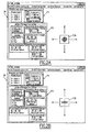
- a graphical user interface IA or IB comprises, for example, a first window F1 for managing a spot, a second window F2 for continuous shooting, and a moving target CA or CB on a zone of the screen.
- This moving target can be realized for example in the form of a conventional representation target consisting of a set of concentric circles and a cross of sight in the center of these circles ( Figure 2A ), or in the form of a graduated cursor and a superimposed cross Figure 2B )
- the system is arranged so that the target of the active MAM pattern is visible by the two eyes OD1 and OG1 of the subject to be examined.
- a sight with both eyes can indeed improve the performance of fixations or stability, and facilitate the examination.
- the image of the pattern is introduced into the optical path between the reference source SLD and the eye examined by a separator BST3.
- This separator can be chosen dichroic so as to reflect 50% of all the light coming from the MAM pattern toward the examined OEX eye, and transmit the remaining 50% to the other eye OV1 or OV2 to allow a sighting of both eyes.
- the dichroic splitter BST3 then transmits all of the light from the SLD reference source to the examined OEX eye, taking advantage of a spectrum difference between the SLD reference source (830 nm) and the MAM pattern (800 nm).
- a 50/50 fully spectrally neutral splitter plate is also suitable, but 50% of the SLD light is sent to the un-studied eye.
- a filter can eliminate this image if it is considered troublesome by the subject.
- the system In order to be able to examine any of the two eyes while providing sighting for both eyes, the system has a central OEX examination location, as well as two OV1 and OV2 sighting locations on both sides of this location. OEX exam.
- the right eye When the left eye is in the central location to be examined, the right eye receives the image of the MAM pattern in its sighting location OV1 by retractable return means, for example two mirrors MT1 and MT2.
- retractable return means for example two mirrors MT1 and MT2.
- the deflection means may be retracted or canceled and the image of the MAM pattern reaches the left eye in its OV2 sighting location.
- the system may also include, or collaborate with, IRIS tracking means of the movements of the eye to be examined, collaborating with the tomography device. It may be for example a camera with image recognition performing tracking or "tracking", for example of the retina or pupil or edges of the iris, so as to detect and evaluate the movements of the 'eye.
- Knowing the movements of the eye then allows the system to adapt to the movements of the area to be examined, for example by coordinating and setting and shooting with the different detected or predicted positions of this area to be examined, or by allowing a spatial and / or temporal optimization of the adaptive optics. It is possible for example to take advantage of the natural periods of stabilization of the pupil or the retina to achieve all or part of the adjustments or desired measurements.
- the image of the examined eye reaches the IRIS eye tracking means by a separator BST2 inserted in the optical path, for example between the eye and the reference source SLD.
- this separator BST2 is dichroic and the monitoring of the movements of the eye is in non-visible light, for example infrared.
- the IRIS tracking means may comprise for example a device for measuring eye movements, such as those developed by the company Mperivision.
- the invention may in particular be implemented to make or complete a retinal imaging device, or corneal topography, or measuring a film of tears.
Landscapes
- Life Sciences & Earth Sciences (AREA)
- Health & Medical Sciences (AREA)
- Medical Informatics (AREA)
- Biophysics (AREA)
- Ophthalmology & Optometry (AREA)
- Engineering & Computer Science (AREA)
- Biomedical Technology (AREA)
- Heart & Thoracic Surgery (AREA)
- Physics & Mathematics (AREA)
- Molecular Biology (AREA)
- Surgery (AREA)
- Animal Behavior & Ethology (AREA)
- General Health & Medical Sciences (AREA)
- Public Health (AREA)
- Veterinary Medicine (AREA)
- Eye Examination Apparatus (AREA)
- Medicines Containing Antibodies Or Antigens For Use As Internal Diagnostic Agents (AREA)
Description
- La présente invention concerne un dispositif de visée pour un examen de l'oeil. Elle vise également un procédé de visée mis en oeuvre dans ce dispositif, ainsi qu'un système d'examen de l'oeil par tomographie in vivo équipé de ce dispositif.
- Lors de l'examen de l'oeil en général, et en particulier de la rétine, les mouvements inconscients de l'oeil, même pendant une fixation, peuvent considérablement limiter les performances de l'examen.
- Les mouvements résiduels pendant une fixation sont de trois types :
- Nystagmus physiologique (ou tremor) : oscillations très rapides (de 40 à 100 Hz), de petite amplitude (déplacement des images de l'ordre du micron sur la rétine) ;
- Dérives : mouvements lents (1 µm en quelques ms), décorrélés d'un oeil à l'autre ;
- Micro-saccades : mouvements très rapides (quelques centaines par seconde), corrélés entre les yeux, de recentrage approximatif du champ.
- L'expérience montre que les performances de fixation d'un sujet donné sont très variables, suivant son état de fatigue, suivant l'éclairage ambiant, ou suivant la durée de la fixation. Il est par ailleurs connu que la fixation avec deux yeux est plus performante qu'avec un seul.
-
US 3 836 238 etUS 5 565 949 divulguent des dispositifs d'affichage de cibles de fixation pour un examen de l'oeil d'un sujet. Des intervalles de fixation sont alternés avec des intervalles de repos. - Le dispositif de
US 3 836 238 est divulgué en combinaison avec un aberromètre, alors que le dispositif deUS 5 565 949 est destiné à effectuer des mesures de champ visuel. - L'adjonction d'un système de compensation des mouvements de l'oeil peut se révéler très complexe, coûteux, et parfois incompatible avec l'instrumentation existante.
- Le but de la présente invention est de remédier à ces inconvénients en proposant un dispositif de visée qui optimise la performance de fixation du sujet, ce dispositif de visée étant destiné à équiper un système d'examen en lui procurant une très bonne résolution spatiale. Il s'agit donc d'augmenter la performance globale de l'examen en augmentant celle du sujet.
- Suivant l'invention, le dispositif de visée comprend au moins une cible mobile présentant une forme et une trajectoire programmables, cette ou ces cibles étant affichée(s) sur des moyens de visualisation tels qu'un écran et visible des deux yeux, pendant la durée de l'examen.
- Dans un premier mode opératoire, la ou les cibles sont déplacées de manière à alterner des intervalles de fixation sur une position donnée avec des intervalles dits de repos sur une ou plusieurs autres positions. La durée des intervalles de fixation peut être ajustée pour en optimiser la qualité. On peut également ajuster la diversité, la position et la durée des positions de repos.
- Dans un second mode opératoire, on commande un mouvement continu qui forcerait le regard du sujet à suivre une cible mobile. Si les performances de suivi sont meilleures que celles de fixation, la connaissance a priori de la trajectoire permettrait de recaler les images de l'oeil obtenues avec une meilleure précision qu'elles ne le sont quand on observe une cible immobile.
- Suivant un autre aspect de l'invention, il est proposé un système d'examen de l'oeil par tomographie in vivo comprenant :
- un interféromètre de Michelson, réalisant un montage d'OCT plein champ,
- un dispositif d'optique adaptative, disposé entre l'interféromètre et un oeil à examiner, réalisant la correction des fronts d'onde en provenance de l'oeil mais aussi à destination de l'oeil, et
- un dispositif de détection, disposé en aval de l'interféromètre, permettant sans modulation ni détection synchrone, de réaliser la mesure interférométrique selon le principe de l'OCT,
- Ce dispositif de visée permet de guider le regard du patient tout en assurant son confort visuel et en optimisant ses performances de fixation.
- D'autres avantages et caractéristiques de l'invention apparaîtront à l'examen de la description détaillée d'un mode de mise en oeuvre nullement limitatif, et des figures annexées dans lesquelles :
- la
figure 1 illustre la structure d'un système de tomographie in vivo intégrant un dispositif de visée selon l'invention, et - les
figures 2A et 2B représentent respectivement un premier et un second exemples de réalisation de mires actives mises en oeuvre dans un dispositif de visée selon l'invention, sur un écran d'un ordinateur. - la
figure 3 est un schéma d'un autre exemple de réalisation d'un système de tomographie in vivo selon l'invention. - On va maintenant décrire, en référence à la
figure 1 , un exemple pratique de réalisation d'un système de tomographie in vivo selon l'invention. Ce système comprend un interféromètre, de type Michelson, comportant un bras de mesure prévu pour illuminer l'oeil et collecter la lumière renvoyée, et un bras de référence prévu pour illuminer un miroir mobile permettant l'exploration en profondeur du tissu rétinien. - L'interféromètre est utilisé en lumière polarisée de façon rectiligne et perpendiculaire dans les deux bras. La source de lumière S est une diode à faible longueur de cohérence temporelle (par exemple, 12 µm), dont le spectre est centré sur 780 nm. Elle confère par principe au système de tomographie in vivo une résolution axiale égale à la moitié de la longueur de cohérence divisée par l'indice de réfraction du milieu.
- Cette source de lumière S peut être pulsée. Dans ce cas, elle est alors synchronisée avec la prise d'image et la correction adaptative. Le faisceau est limité par un diaphragme de champ correspondant à 1 degré dans le champ de vue de l'oeil (300 µm sur la rétine) et un diaphragme pupillaire correspondant à une ouverture de 7 mm sur un oeil dilaté.
- Un polariseur d'entrée P permet l'équilibrage optimal des flux injectés dans les deux bras de l'interféromètre.
- Les deux bras présentent une configuration dite de Gauss, afocale, qui permet le transport des pupilles, d'une part, et la matérialisation d'une image intermédiaire du champ où un diaphragme bloque une grande part du reflet cornéen, d'autre part. Des lames quart d'onde assurent par la rotation de la polarisation de la seule lumière renvoyée par l'oeil, et le miroir mobile, un filtrage efficace des réflexions parasités dans le système de tomographie in vivo selon l'invention.
- Afin de conserver l'égalité des chemins optiques dans les deux bras, avec le même transport des pupilles et du champ, le bras de référence est similaire au bras de mesure, mais avec une optique statique.
- On va maintenant décrire la voie de détection du système de tomographie in vivo selon l'invention. Les deux faisceaux sur le bras de sortie sont encore polarisés perpendiculairement, et ils n'interfèrent que s'ils sont projetés sur une direction commune. Un prisme de Wollaston W a pour fonction de projeter simultanément les deux rayonnements sur deux directions d'analyse perpendiculaires. On peut alors effectuer une mesure simultanée de l'intensité après interférence dans deux états d'interférence en opposition, sans modulation ni détection synchrone, sur un détecteur bidimensionnel unique. L'adjonction d'une lame quart d'onde, après division du faisceau, permet d'accéder à deux mesures supplémentaires, levant ainsi toute ambiguïté entre amplitude et phase des franges. Une lame demi onde à l'entrée de la voie de détection permet d'orienter convenablement les polarisations incidentes.
- Le prisme de Wollaston est placé dans un plan pupillaire, donc conjugué du cube séparateur de l'interféromètre de Michelson. L'angle de séparation du prisme de Wollaston est choisi en fonction du champ à observer. La longueur focale de l'objectif final détermine le pas d'échantillonnage des quatre images.
- Le détecteur est du type CCD, avec une cadence d'image supérieure à 30 images par seconde. Ce détecteur est associé à un calculateur dédié (non représenté) dans lequel est réalisé le traitement numérique des images : extraction des quatre mesures, étalonnage, calcul de l'amplitude des franges.
- La correction adaptative des fronts d'onde est réalisée en amont de l'interféromètre, donc dans le bras de mesure. Chaque point de la source S voit ainsi son image sur la rétine corrigée des aberrations, et l'image en retour est également corrigée. L'amplitude des franges est alors maximale.
- Le sous-ensemble d'optique adaptative comprend un miroir déformable MD. La mesure de front d'onde est faite par un analyseur SH de type Shack-Hartmann sur le faisceau de retour d'un spot lumineux lui-même imagé sur la rétine via le miroir déformable MD. La longueur d'onde d'analyse est de 820 nm. L'éclairage est continu et fourni par une diode SLD superluminescente temporellement incohérente. Le dimensionnement de l'analyseur correspond à une optimisation entre sensibilité photométrique et échantillonnage du front d'onde. La cadence de rafraîchissement de la commande du miroir déformable MD peut atteindre 150 Hz. Un calculateur dédié (non représenté) gère la boucle d'optique adaptative. La commande est toutefois synchronisée pour geler la forme du miroir pendant la mesure interférométrique.
- Un contrôle approprié de la focalisation de la voie d'analyse, au moyen d'une lentille LA2, permet d'adapter la distance de focalisation à la couche sélectionnée par l'interféromètre. Cette disposition est capitale pour conserver un contraste optimal à toute profondeur.
- Le miroir déformable MD est conjugué de la pupille du système et de l'oeil. Le champ du système est défini par le diaphragme de champ DCM d'entrée du système. Il est de préférence choisi à une valeur inférieure à celle du champ d'isoplanétisme de l'oeil, ce qui garantit la validité de la correction adaptative dans le champ sur la seule mesure de front d'onde réalisée à partir du spot, au centre du champ. A titre d'exemple, le champ du système peut être choisi égal à 1 degré, mais la valeur de ce champ pourrait être augmentée.
- De plus, la rotation du miroir déformable MD permet de choisir l'angle d'arrivée du faisceau dans l'oeil, donc la portion de rétine étudiée.
- L'adjonction de verres correcteurs de la vue du sujet, donc des bas ordres d'aberrations géométriques tels que le focus ou l'astigmatisme, juste devant l'oeil, permet de relâcher les exigences sur la course du miroir déformable MD, et garantit également une meilleure visée. Un système correcteur adaptatif par transmission peut être utilisé de préférence à des verres fixes pour une correction optimale.
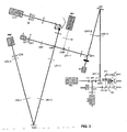
- Ainsi qu'illustré en
figure 3 , le système peut en outre comprendre des moyens d'imagerie classique, comme une caméra IMG, permettant d'associer les mesures interférométriques avec une imagerie simple des zones examinées, par exemple pour faciliter l'exploration et la sélection des zones à examiner. - Placé directement en sortie (au retour) du bras de mesure, donc juste avant le cube polarisant CPR de l'interféromètre, un second cube polarisant CNPI permet de dévier le faisceau de retour vers une caméra d'imagerie IMG disposant de ses propres moyens de focalisation LI de l'image. Sur cette voie, une image directe de la zone rétinienne visée sera observable. On peut en particulier agencer le bras de mesure et cette voie additionnelle de sorte qu'ils procurent un champ d'observation plus large que le mode interférométrique, dont le champ est limité en particulier par la technique de mesure de contraste interférométrique en elle-même.
- Un dispositif de visée selon l'invention, collaboratif ou actif, est installé en amont de l'ensemble. Ce système de visée, qui comprend une mire active MAM, présente au sujet l'image d'un point lumineux s'écartant périodiquement de l'axe de visée recherché. Le patient est alors invité à suivre tous les mouvements de cette image. Chaque fois que l'image revient sur l'axe, et après un temps de latence ajustable, une série de mesures interférométriques est réalisée. Le déplacement périodique du regard permet d'obtenir du patient une meilleure capacité de fixation quand il vise l'axe recherché. L'amplitude et la fréquence sont adaptables au sujet et aux mesures entreprises. Pour des raisons de commodité, la mire peut être réalisée avec un simple ordinateur de bureau sur lequel un point lumineux est affiché et déplacé. La mire active MAM, l'optique adaptative, la source S et la prise d'image sont synchronisées.
- La mire active peut être réalisée sur l'écran d'un ordinateur ou d'un moniteur connecté à un système de commande (non représenté) du dispositif de visée, comme l'illustrent les
figures 2A et 2B . Dans ce mode de réalisation, une interface graphique utilisateur IA ou IB comprend par exemple une première fenêtre F1 de gestion d'un spot, une seconde fenêtre F2 de prise d'image en rafale, et une cible mobile CA ou CB sur une zone de l'écran. Cette cible mobile peut être réalisée par exemple sous la forme d'une cible de représentation conventionnelle constituée d'un ensemble de cercles concentriques et d'une croix de visée au centre de ces cercles (Figure 2A ), ou bien encore sous la forme d'un curseur gradué et d'une croix de visée superposée (Figure 2B ) - Dans l'exemple illustré en
figure 3 , le système est agencé pour que la cible de la mire active MAM soit visible par les deux yeux OD1 et OG1 du sujet à examiner. Une visée avec les deux yeux peut en effet permettre d'améliorer les performances de fixations ou de stabilité, et faciliter l'examen. Dans cet exemple, l'image de la mire est introduite dans le trajet optique entre la source de référence SLD et l'oeil examiné par une séparatrice BST3. - Cette séparatrice peut être choisie dichroïque de manière à réfléchir 50% de toute la lumière venant de la mire MAM vers l'oeil examiné OEX, et transmettre les 50% restant vers l'autre oeil OV1 ou OV2 pour permettre une visée des deux yeux. La séparatrice dichroïque BST3 transmet alors toute la lumière de la source de référence SLD vers l'oeil examiné OEX, en profitant d'une différence de spectre entre la source de référence SLD (830 nm) et la mire MAM (800 nm). Une lame séparatrice 50/50 totalement neutre spectralement convient également, mais 50% de la lumière de la SLD est alors envoyé vers l'oeil qui n'est pas étudié. Un filtre peut permettre d'éliminer cette image si elle est jugée gênante par le sujet.
- De façon à pouvoir examiner n'importe lequel des deux yeux tout en assurant une visée des deux yeux, le système présente un emplacement central d'examen OEX, ainsi que deux emplacements de visée OV1 et OV2 répartis des deux côtés de cet emplacement d'examen OEX.
- Lorsque l'oeil gauche est à l'emplacement central pour être examiné, l'oeil droit reçoit l'image de la mire MAM dans son emplacement de visée OV1 par des moyens de renvoi escamotables, par exemples deux miroirs MT1 et MT2. Lorsque c'est l'oeil droit qui est à l'emplacement d'examen OEX, les moyens de renvoi peuvent être escamotés ou annulés et l'image de la mire MAM parvient à l'oeil gauche dans son emplacement de visée OV2.
- Ainsi qu'illustré en
figure 3 , le système peut également comprendre, ou collaborer avec, des moyens de suivi IRIS des mouvements de l'oeil à examiner, collaborant avec le dispositif de tomographie. Il peut s'agir par exemple d'une caméra avec reconnaissance d'image réalisant un suivi ou « tracking », par exemple de la rétine ou de pupille ou des bords de l'iris, de façon à détecter et évaluer les mouvements de l'oeil. - La connaissance des mouvements de l'oeil permet alors au système de s'adapter aux déplacements de la zone à examiner, par exemple en coordonnant et les réglages et les prises de vue avec les différentes positions détectées ou prévues de cette zone à examiner, ou en permettant une optimisation spatiale et/ou temporelle de l'optique adaptive. Il est possible par exemple de profiter des périodes naturelles de stabilisation de la pupille ou de la rétine pour réaliser tout ou partie des réglages ou des mesures souhaités.
- L'image de l'oeil examiné parvient aux moyens de suivi de l'oeil IRIS par une séparatrice BST2 insérée dans le trajet optique, par exemple entre l'oeil et la source de référence SLD. De façon avantageuse, par exemple pour ne pas gêner le sujet, cette séparatrice BST2 est dichroïque et le suivi des mouvements de l'oeil se fait en lumière non visible, par exemple infrarouge.
- Les moyens de suivi IRIS peuvent comprendre par exemple un dispositif de mesure des déplacements oculaires, comme ceux développés par la société Métrovision.
- L'invention peut en particulier être mise en oeuvre pour réaliser ou compléter un dispositif d'imagerie rétinienne, ou de topographie cornéenne, ou de mesure d'un film de larmes.
- Bien sûr, l'invention n'est pas limitée aux exemples qui viennent d'être décrits et de nombreux aménagements peuvent être apportés à ces exemples sans sortir du cadre de l'invention.
Claims (13)
- Dispositif de visée (MAM) pour équiper un système d'examen de l'oeil d'un sujet, comprenant au moins une cible mobile (CA, CB) présentant une forme programmable ou une trajectoire programmable, ladite cible étant affichée sur des moyens de visualisation et visible d'au moins un oeil dudit sujet, pendant la durée de l'examen, ledit dispositif comprenant des moyens pour déplacer la ou les cible(s) de manière à alterner des intervalles de fixation sur une position donnée avec des intervalles dits de repos sur une ou plusieurs autres positions, ledit dispositif étant caractérisé en ce qu'il comprend en outre des moyens pour ajuster la durée des intervalles de fixation.
- Dispositif selon la revendication 1, caractérisé en ce qu'il comprend en outre des moyens pour ajuster la diversité des positions de repos.
- Dispositif selon l'une des revendications 1 ou 2, caractérisé en ce qu'il comprend en outre des moyens pour ajuster la durée des positions de repos.
- Dispositif selon l'une des revendications 1 à 3, caractérisé en ce qu'il comprend en outre des moyens pour commander un mouvement continu d'une cible mobile.
- Procédé de visée pour un examen de l'oeil d'un sujet, mis en oeuvre dans un dispositif selon l'une des revendications précédentes, comprenant un affichage sur des moyens de visualisation, pendant la durée de l'examen, d'au moins une cible mobile (CA, CB) présentant une forme programmable ou une trajectoire programmables et visible d'au moins un oeil dudit sujet, ledit procédé comprenant un déplacement de la ou des cible(s) de manière à alterner des intervalles de fixation sur une position donnée avec des intervalles dits de repos sur une ou plusieurs autres positions, ledit procédé-étant caractérisé en ce qu'il comprend en outre un ajustement de la durée des intervalles de fixation.
- Procédé selon la revendication 5, caractérisé en qu'il comprend en outre un ajustement de la diversité des positions de repos.
- Procédé de visée pour un examen de l'oeil d'un sujet, mis en oeuvre dans un dispositif selon l'une des revendications précédentes, comprenant un affichage sur des moyens de visualisation, pendant la durée de l'examen, d'au moins une cible mobile (CA, CB) présentant une forme programmable ou une trajectoire programmable et visible d'au moins un oeil dudit sujet, ledit procédé étant caractérisé en ce qu'il comprend en outre une commande d'un mouvement continu d'une cible mobile.
- Procédé selon l'une des revendications 5 à 7, caractérisé en ce qu'il comprend en outre un suivi des mouvements de l'oeil à examiner.
- Procédé selon la revendication 8, caractérisé en ce que le suivi des mouvements de l'oeil à examiner se fait par imagerie utilisant un spectre non visible.
- Système d'examen de l'oeil par tomographie in vivo, comprenant :- un interféromètre de Michelson, réalisant un montage de tomographie optique cohérente OCT plein champ,- des moyens d'optique adaptative, disposés entre l'interféromètre et un oeil à examiner, réalisant une correction des fronts d'onde en provenance de l'oeil maïs aussi à destination de l'oeil et- des moyens de détection, disposé en aval de l'interféromètre, permettant de réaliser la mesure interférométrique selon le principe de l'OCT plein champ sans modulation ni détection synchrone, caractérisé en ce qu'il comprend en outre un dispositif de visée comprenant au moins une cible mobile présentant une forme programmable ou une trajectoire programmable, ladite cible étant affichée sur des moyens de visualisation et visible d'au moins un des yeux dudit patient, pendant la durée de l'examen.
- Système selon la revendications 10 , caractérisé en ce qu'il comprend des moyens (IRIS) de suivi des mouvements de l'oeil à examiner (OEX), collaborant avec le dispositif de tomographie.
- Système selon l'une des revendications 10 ou 11, caractérisé en ce qu'il comprend des moyens pour faire parvenir l'image de la cible aux deux yeux (OV1, OEX) du sujet à examiner.
- Système selon l'une des revendications 10 à 12, caractérisé en ce qu'il comprend des moyens pour faire parvenir l'image de la cible à l'oeil non examiné du sujet sélectivement d'un côté (OV1) ou de l'autre (OV2) de l'oeil examiné (OEX).
Applications Claiming Priority (2)
| Application Number | Priority Date | Filing Date | Title |
|---|---|---|---|
| FR0400581A FR2865371B1 (fr) | 2004-01-22 | 2004-01-22 | Dispositif et procede de visee pour un examen de l'oeil, systeme d'examen de l'oeil par tomographie in vivo equipe de ce dispositif |
| PCT/FR2005/000133 WO2005079655A1 (fr) | 2004-01-22 | 2005-01-21 | Appareil d’examen de l’oeil par tomographe avec dispositif de visee |
Publications (2)
| Publication Number | Publication Date |
|---|---|
| EP1706017A1 EP1706017A1 (fr) | 2006-10-04 |
| EP1706017B1 true EP1706017B1 (fr) | 2013-11-27 |
Family
ID=34717341
Family Applications (1)
| Application Number | Title | Priority Date | Filing Date |
|---|---|---|---|
| EP05717462.5A Not-in-force EP1706017B1 (fr) | 2004-01-22 | 2005-01-21 | Appareil d'examen de l'oeil par tomographie avec dispositif de visee |
Country Status (6)
| Country | Link |
|---|---|
| US (2) | US7438415B2 (fr) |
| EP (1) | EP1706017B1 (fr) |
| JP (1) | JP2007518505A (fr) |
| CA (1) | CA2553741C (fr) |
| FR (1) | FR2865371B1 (fr) |
| WO (1) | WO2005079655A1 (fr) |
Families Citing this family (20)
| Publication number | Priority date | Publication date | Assignee | Title |
|---|---|---|---|---|
| GB2429522A (en) * | 2005-08-26 | 2007-02-28 | Univ Kent Canterbury | Optical mapping apparatus |
| US7400410B2 (en) * | 2005-10-05 | 2008-07-15 | Carl Zeiss Meditec, Inc. | Optical coherence tomography for eye-length measurement |
| JP4822331B2 (ja) * | 2006-06-22 | 2011-11-24 | 株式会社トプコン | 眼科装置 |
| JP4822332B2 (ja) * | 2006-06-22 | 2011-11-24 | 株式会社トプコン | 眼科装置 |
| WO2008052793A1 (fr) * | 2006-11-02 | 2008-05-08 | Heidelberg Engineering Gmbh | Procédé et appareil de diagnostic de la rétine |
| US8016420B2 (en) | 2007-05-17 | 2011-09-13 | Amo Development Llc. | System and method for illumination and fixation with ophthalmic diagnostic instruments |
| US8348429B2 (en) | 2008-03-27 | 2013-01-08 | Doheny Eye Institute | Optical coherence tomography device, method, and system |
| US11839430B2 (en) | 2008-03-27 | 2023-12-12 | Doheny Eye Institute | Optical coherence tomography-based ophthalmic testing methods, devices and systems |
| US8820931B2 (en) * | 2008-07-18 | 2014-09-02 | Doheny Eye Institute | Optical coherence tomography-based ophthalmic testing methods, devices and systems |
| WO2010117386A1 (fr) * | 2009-04-10 | 2010-10-14 | Doheny Eye Institute | Procédés, dispositifs et systèmes d'examen ophtalmique |
| US10772497B2 (en) | 2014-09-12 | 2020-09-15 | Envision Diagnostics, Inc. | Medical interfaces and other medical devices, systems, and methods for performing eye exams |
| US9226856B2 (en) | 2013-03-14 | 2016-01-05 | Envision Diagnostics, Inc. | Inflatable medical interfaces and other medical devices, systems, and methods |
| US9424572B2 (en) | 2014-03-04 | 2016-08-23 | Bank Of America Corporation | Online banking digital wallet management |
| US11039741B2 (en) | 2015-09-17 | 2021-06-22 | Envision Diagnostics, Inc. | Medical interfaces and other medical devices, systems, and methods for performing eye exams |
| WO2017190087A1 (fr) | 2016-04-30 | 2017-11-02 | Envision Diagnostics, Inc. | Dispositifs, systèmes et procédés médicaux de mise en œuvre d'examens oculaires et d'oculométrie |
| GB201707239D0 (en) | 2017-05-05 | 2017-06-21 | Univ Edinburgh | Optical system and method |
| US10524165B2 (en) | 2017-06-22 | 2019-12-31 | Bank Of America Corporation | Dynamic utilization of alternative resources based on token association |
| US10511692B2 (en) | 2017-06-22 | 2019-12-17 | Bank Of America Corporation | Data transmission to a networked resource based on contextual information |
| US10313480B2 (en) | 2017-06-22 | 2019-06-04 | Bank Of America Corporation | Data transmission between networked resources |
| EP3572765A1 (fr) * | 2018-05-23 | 2019-11-27 | Haag-Streit Ag | Appareil et procédé pour tomographie par cohérence optique |
Family Cites Families (12)
| Publication number | Priority date | Publication date | Assignee | Title |
|---|---|---|---|---|
| US3836238A (en) * | 1973-05-09 | 1974-09-17 | Tropel | Viewable target system for eye examining instrument |
| GB2031607B (en) * | 1978-09-12 | 1983-05-25 | Crick J | Apparatus for detecting visual field defects of the eye |
| US4995717A (en) * | 1989-08-22 | 1991-02-26 | The University Court Of The University Of Glasgow | Device for moving eye campimetry |
| US5565949A (en) * | 1995-07-10 | 1996-10-15 | Kasha, Jr.; John R. | Visual field perimetry on a small computer screen |
| US6271914B1 (en) * | 1996-11-25 | 2001-08-07 | Autonomous Technologies Corporation | Objective measurement and correction of optical systems using wavefront analysis |
| US5777719A (en) * | 1996-12-23 | 1998-07-07 | University Of Rochester | Method and apparatus for improving vision and the resolution of retinal images |
| IL136239A0 (en) * | 1997-11-21 | 2001-05-20 | Autonomous Technologies Corp | Objective measurement and correction of optical systems using wavefront analysis |
| FR2791548B1 (fr) * | 1999-04-01 | 2001-07-06 | Univ Paris Vii Denis Diderot | Dispositif d'observation d'un corps a haute resolution |
| AU2002305045A1 (en) * | 2001-03-15 | 2002-10-03 | Wavefront Sciences, Inc. | Tomographic wavefront analysis system |
| WO2003020121A1 (fr) | 2001-08-30 | 2003-03-13 | University Of Rochester | Optique adaptative dans un ophtalmoscope laser a balayage |
| US7006232B2 (en) * | 2002-04-05 | 2006-02-28 | Case Western Reserve University | Phase-referenced doppler optical coherence tomography |
| AU2003245458A1 (en) | 2002-06-12 | 2003-12-31 | Advanced Research And Technology Institute, Inc. | Method and apparatus for improving both lateral and axial resolution in ophthalmoscopy |
-
2004
- 2004-01-22 FR FR0400581A patent/FR2865371B1/fr not_active Expired - Fee Related
-
2005
- 2005-01-21 WO PCT/FR2005/000133 patent/WO2005079655A1/fr active Application Filing
- 2005-01-21 US US10/586,839 patent/US7438415B2/en not_active Expired - Fee Related
- 2005-01-21 EP EP05717462.5A patent/EP1706017B1/fr not_active Not-in-force
- 2005-01-21 JP JP2006550237A patent/JP2007518505A/ja active Pending
- 2005-01-21 CA CA2553741A patent/CA2553741C/fr not_active Expired - Fee Related
-
2008
- 2008-09-12 US US12/210,058 patent/US7658495B2/en not_active Expired - Fee Related
Also Published As
| Publication number | Publication date |
|---|---|
| US7658495B2 (en) | 2010-02-09 |
| US20070177104A1 (en) | 2007-08-02 |
| FR2865371B1 (fr) | 2007-12-21 |
| CA2553741A1 (fr) | 2005-09-01 |
| WO2005079655A1 (fr) | 2005-09-01 |
| US7438415B2 (en) | 2008-10-21 |
| JP2007518505A (ja) | 2007-07-12 |
| CA2553741C (fr) | 2014-03-18 |
| FR2865371A1 (fr) | 2005-07-29 |
| US20090002630A1 (en) | 2009-01-01 |
| EP1706017A1 (fr) | 2006-10-04 |
Similar Documents
| Publication | Publication Date | Title |
|---|---|---|
| EP1706017B1 (fr) | Appareil d'examen de l'oeil par tomographie avec dispositif de visee | |
| EP1706705B1 (fr) | Tomographie a haute resolution laterale et axiale de la retine | |
| US9931033B2 (en) | System and method for controlling a fundus imaging apparatus | |
| US6439720B1 (en) | Method and apparatus for measuring optical aberrations of the human eye | |
| RU2573179C2 (ru) | Последовательный датчик волнового фронта с большим диоптрийным диапазоном, предоставляющий информацию в реальном времени | |
| RU2600854C2 (ru) | Офтальмологический датчик волнового фронта, действующий в режиме параллельного отбора и синхронного детектирования | |
| CA2975903A1 (fr) | Systemes et procedes de tomographie par coherence optique a ligne de retard a plusieurs foyers | |
| EP1711776B1 (fr) | Dispositif et procede pour mesurer le contraste des franges dans un interferometre de michelson, et systeme d'examen de l'oeil incluant un tel dispositif | |
| JP2018047050A (ja) | 検眼装置及び検眼プログラム | |
| US7419264B1 (en) | Ophthalmic aberrometer for measuring aberrations in the eye | |
| WO2005079657A2 (fr) | Dispositif et procede pour compenser la birefringence corneenne de l'oeil | |
| JP6108810B2 (ja) | 眼科装置およびその制御方法 | |
| US20220330813A1 (en) | Methods and systems for thickness measurements using spectrally resolved full gradient topography | |
| JP6916011B2 (ja) | 眼科装置 | |
| dos Santos Anjos | Development of a fundus camera for analysis of photoreceptor directionality in the healthy retina | |
| Thurin | Density of the Human Photoreceptor Mosaic Analyzed with Ocular Speckle Interferometry and Ocular Correlography |
Legal Events
| Date | Code | Title | Description |
|---|---|---|---|
| PUAI | Public reference made under article 153(3) epc to a published international application that has entered the european phase |
Free format text: ORIGINAL CODE: 0009012 |
|
| 17P | Request for examination filed |
Effective date: 20060809 |
|
| AK | Designated contracting states |
Kind code of ref document: A1 Designated state(s): AT BE BG CH CY CZ DE DK EE ES FI FR GB GR HU IE IS IT LI LT LU MC NL PL PT RO SE SI SK TR |
|
| DAX | Request for extension of the european patent (deleted) | ||
| 17Q | First examination report despatched |
Effective date: 20090403 |
|
| RIN1 | Information on inventor provided before grant (corrected) |
Inventor name: GENDRON, ERIC Inventor name: GLANC, MARIE Inventor name: LACOMBE, FRANCOIS Inventor name: STEFANOVITCH, DOUCHANE Inventor name: LAFAILLE, DAVID |
|
| GRAP | Despatch of communication of intention to grant a patent |
Free format text: ORIGINAL CODE: EPIDOSNIGR1 |
|
| INTG | Intention to grant announced |
Effective date: 20130523 |
|
| GRAP | Despatch of communication of intention to grant a patent |
Free format text: ORIGINAL CODE: EPIDOSNIGR1 |
|
| INTG | Intention to grant announced |
Effective date: 20130717 |
|
| GRAS | Grant fee paid |
Free format text: ORIGINAL CODE: EPIDOSNIGR3 |
|
| GRAA | (expected) grant |
Free format text: ORIGINAL CODE: 0009210 |
|
| AK | Designated contracting states |
Kind code of ref document: B1 Designated state(s): AT BE BG CH CY CZ DE DK EE ES FI FR GB GR HU IE IS IT LI LT LU MC NL PL PT RO SE SI SK TR |
|
| REG | Reference to a national code |
Ref country code: GB Ref legal event code: FG4D Free format text: NOT ENGLISH |
|
| REG | Reference to a national code |
Ref country code: CH Ref legal event code: EP |
|
| REG | Reference to a national code |
Ref country code: AT Ref legal event code: REF Ref document number: 642332 Country of ref document: AT Kind code of ref document: T Effective date: 20131215 |
|
| REG | Reference to a national code |
Ref country code: IE Ref legal event code: FG4D Free format text: LANGUAGE OF EP DOCUMENT: FRENCH |
|
| REG | Reference to a national code |
Ref country code: DE Ref legal event code: R096 Ref document number: 602005042001 Country of ref document: DE Effective date: 20140123 |
|
| REG | Reference to a national code |
Ref country code: NL Ref legal event code: VDEP Effective date: 20131127 |
|
| REG | Reference to a national code |
Ref country code: AT Ref legal event code: MK05 Ref document number: 642332 Country of ref document: AT Kind code of ref document: T Effective date: 20131127 |
|
| REG | Reference to a national code |
Ref country code: LT Ref legal event code: MG4D |
|
| PG25 | Lapsed in a contracting state [announced via postgrant information from national office to epo] |
Ref country code: NL Free format text: LAPSE BECAUSE OF FAILURE TO SUBMIT A TRANSLATION OF THE DESCRIPTION OR TO PAY THE FEE WITHIN THE PRESCRIBED TIME-LIMIT Effective date: 20131127 Ref country code: LT Free format text: LAPSE BECAUSE OF FAILURE TO SUBMIT A TRANSLATION OF THE DESCRIPTION OR TO PAY THE FEE WITHIN THE PRESCRIBED TIME-LIMIT Effective date: 20131127 Ref country code: IS Free format text: LAPSE BECAUSE OF FAILURE TO SUBMIT A TRANSLATION OF THE DESCRIPTION OR TO PAY THE FEE WITHIN THE PRESCRIBED TIME-LIMIT Effective date: 20140327 Ref country code: SE Free format text: LAPSE BECAUSE OF FAILURE TO SUBMIT A TRANSLATION OF THE DESCRIPTION OR TO PAY THE FEE WITHIN THE PRESCRIBED TIME-LIMIT Effective date: 20131127 Ref country code: FI Free format text: LAPSE BECAUSE OF FAILURE TO SUBMIT A TRANSLATION OF THE DESCRIPTION OR TO PAY THE FEE WITHIN THE PRESCRIBED TIME-LIMIT Effective date: 20131127 |
|
| PG25 | Lapsed in a contracting state [announced via postgrant information from national office to epo] |
Ref country code: CY Free format text: LAPSE BECAUSE OF FAILURE TO SUBMIT A TRANSLATION OF THE DESCRIPTION OR TO PAY THE FEE WITHIN THE PRESCRIBED TIME-LIMIT Effective date: 20131127 Ref country code: AT Free format text: LAPSE BECAUSE OF FAILURE TO SUBMIT A TRANSLATION OF THE DESCRIPTION OR TO PAY THE FEE WITHIN THE PRESCRIBED TIME-LIMIT Effective date: 20131127 Ref country code: ES Free format text: LAPSE BECAUSE OF FAILURE TO SUBMIT A TRANSLATION OF THE DESCRIPTION OR TO PAY THE FEE WITHIN THE PRESCRIBED TIME-LIMIT Effective date: 20131127 |
|
| PG25 | Lapsed in a contracting state [announced via postgrant information from national office to epo] |
Ref country code: PT Free format text: LAPSE BECAUSE OF FAILURE TO SUBMIT A TRANSLATION OF THE DESCRIPTION OR TO PAY THE FEE WITHIN THE PRESCRIBED TIME-LIMIT Effective date: 20140327 |
|
| BERE | Be: lapsed |
Owner name: OBSERVATOIRE DE PARIS Effective date: 20140131 Owner name: MAUNA KEA TECHNOLOGIES Effective date: 20140131 Owner name: CENTRE NATIONAL DE LA RECHERCHE SCIENTIFIQUE (CNR Effective date: 20140131 |
|
| PG25 | Lapsed in a contracting state [announced via postgrant information from national office to epo] |
Ref country code: EE Free format text: LAPSE BECAUSE OF FAILURE TO SUBMIT A TRANSLATION OF THE DESCRIPTION OR TO PAY THE FEE WITHIN THE PRESCRIBED TIME-LIMIT Effective date: 20131127 |
|
| REG | Reference to a national code |
Ref country code: DE Ref legal event code: R097 Ref document number: 602005042001 Country of ref document: DE |
|
| PG25 | Lapsed in a contracting state [announced via postgrant information from national office to epo] |
Ref country code: LU Free format text: LAPSE BECAUSE OF FAILURE TO SUBMIT A TRANSLATION OF THE DESCRIPTION OR TO PAY THE FEE WITHIN THE PRESCRIBED TIME-LIMIT Effective date: 20140121 Ref country code: RO Free format text: LAPSE BECAUSE OF FAILURE TO SUBMIT A TRANSLATION OF THE DESCRIPTION OR TO PAY THE FEE WITHIN THE PRESCRIBED TIME-LIMIT Effective date: 20131127 Ref country code: CZ Free format text: LAPSE BECAUSE OF FAILURE TO SUBMIT A TRANSLATION OF THE DESCRIPTION OR TO PAY THE FEE WITHIN THE PRESCRIBED TIME-LIMIT Effective date: 20131127 Ref country code: SK Free format text: LAPSE BECAUSE OF FAILURE TO SUBMIT A TRANSLATION OF THE DESCRIPTION OR TO PAY THE FEE WITHIN THE PRESCRIBED TIME-LIMIT Effective date: 20131127 Ref country code: PL Free format text: LAPSE BECAUSE OF FAILURE TO SUBMIT A TRANSLATION OF THE DESCRIPTION OR TO PAY THE FEE WITHIN THE PRESCRIBED TIME-LIMIT Effective date: 20131127 Ref country code: MC Free format text: LAPSE BECAUSE OF FAILURE TO SUBMIT A TRANSLATION OF THE DESCRIPTION OR TO PAY THE FEE WITHIN THE PRESCRIBED TIME-LIMIT Effective date: 20131127 |
|
| REG | Reference to a national code |
Ref country code: CH Ref legal event code: PL |
|
| PG25 | Lapsed in a contracting state [announced via postgrant information from national office to epo] |
Ref country code: DK Free format text: LAPSE BECAUSE OF FAILURE TO SUBMIT A TRANSLATION OF THE DESCRIPTION OR TO PAY THE FEE WITHIN THE PRESCRIBED TIME-LIMIT Effective date: 20131127 |
|
| PLBE | No opposition filed within time limit |
Free format text: ORIGINAL CODE: 0009261 |
|
| STAA | Information on the status of an ep patent application or granted ep patent |
Free format text: STATUS: NO OPPOSITION FILED WITHIN TIME LIMIT |
|
| PG25 | Lapsed in a contracting state [announced via postgrant information from national office to epo] |
Ref country code: LI Free format text: LAPSE BECAUSE OF NON-PAYMENT OF DUE FEES Effective date: 20140131 Ref country code: CH Free format text: LAPSE BECAUSE OF NON-PAYMENT OF DUE FEES Effective date: 20140131 |
|
| 26N | No opposition filed |
Effective date: 20140828 |
|
| REG | Reference to a national code |
Ref country code: IE Ref legal event code: MM4A |
|
| REG | Reference to a national code |
Ref country code: DE Ref legal event code: R097 Ref document number: 602005042001 Country of ref document: DE Effective date: 20140828 |
|
| PG25 | Lapsed in a contracting state [announced via postgrant information from national office to epo] |
Ref country code: BE Free format text: LAPSE BECAUSE OF NON-PAYMENT OF DUE FEES Effective date: 20140131 Ref country code: IE Free format text: LAPSE BECAUSE OF NON-PAYMENT OF DUE FEES Effective date: 20140121 |
|
| PG25 | Lapsed in a contracting state [announced via postgrant information from national office to epo] |
Ref country code: SI Free format text: LAPSE BECAUSE OF FAILURE TO SUBMIT A TRANSLATION OF THE DESCRIPTION OR TO PAY THE FEE WITHIN THE PRESCRIBED TIME-LIMIT Effective date: 20131127 |
|
| REG | Reference to a national code |
Ref country code: FR Ref legal event code: PLFP Year of fee payment: 12 |
|
| PG25 | Lapsed in a contracting state [announced via postgrant information from national office to epo] |
Ref country code: BG Free format text: LAPSE BECAUSE OF FAILURE TO SUBMIT A TRANSLATION OF THE DESCRIPTION OR TO PAY THE FEE WITHIN THE PRESCRIBED TIME-LIMIT Effective date: 20131127 |
|
| PG25 | Lapsed in a contracting state [announced via postgrant information from national office to epo] |
Ref country code: GR Free format text: LAPSE BECAUSE OF FAILURE TO SUBMIT A TRANSLATION OF THE DESCRIPTION OR TO PAY THE FEE WITHIN THE PRESCRIBED TIME-LIMIT Effective date: 20140228 Ref country code: IT Free format text: LAPSE BECAUSE OF FAILURE TO SUBMIT A TRANSLATION OF THE DESCRIPTION OR TO PAY THE FEE WITHIN THE PRESCRIBED TIME-LIMIT Effective date: 20131127 |
|
| PG25 | Lapsed in a contracting state [announced via postgrant information from national office to epo] |
Ref country code: TR Free format text: LAPSE BECAUSE OF FAILURE TO SUBMIT A TRANSLATION OF THE DESCRIPTION OR TO PAY THE FEE WITHIN THE PRESCRIBED TIME-LIMIT Effective date: 20131127 Ref country code: HU Free format text: LAPSE BECAUSE OF FAILURE TO SUBMIT A TRANSLATION OF THE DESCRIPTION OR TO PAY THE FEE WITHIN THE PRESCRIBED TIME-LIMIT; INVALID AB INITIO Effective date: 20050121 |
|
| REG | Reference to a national code |
Ref country code: FR Ref legal event code: PLFP Year of fee payment: 13 |
|
| REG | Reference to a national code |
Ref country code: FR Ref legal event code: PLFP Year of fee payment: 14 |
|
| PGFP | Annual fee paid to national office [announced via postgrant information from national office to epo] |
Ref country code: FR Payment date: 20190130 Year of fee payment: 15 Ref country code: DE Payment date: 20190114 Year of fee payment: 15 Ref country code: GB Payment date: 20190118 Year of fee payment: 15 |
|
| REG | Reference to a national code |
Ref country code: DE Ref legal event code: R119 Ref document number: 602005042001 Country of ref document: DE |
|
| GBPC | Gb: european patent ceased through non-payment of renewal fee |
Effective date: 20200121 |
|
| PG25 | Lapsed in a contracting state [announced via postgrant information from national office to epo] |
Ref country code: FR Free format text: LAPSE BECAUSE OF NON-PAYMENT OF DUE FEES Effective date: 20200131 Ref country code: DE Free format text: LAPSE BECAUSE OF NON-PAYMENT OF DUE FEES Effective date: 20200801 Ref country code: GB Free format text: LAPSE BECAUSE OF NON-PAYMENT OF DUE FEES Effective date: 20200121 |