EP1705670A2 - Functionally graded rare earth permanent magnet - Google Patents
Functionally graded rare earth permanent magnet Download PDFInfo
- Publication number
- EP1705670A2 EP1705670A2 EP06250544A EP06250544A EP1705670A2 EP 1705670 A2 EP1705670 A2 EP 1705670A2 EP 06250544 A EP06250544 A EP 06250544A EP 06250544 A EP06250544 A EP 06250544A EP 1705670 A2 EP1705670 A2 EP 1705670A2
- Authority
- EP
- European Patent Office
- Prior art keywords
- magnet body
- atom
- rare earth
- magnet
- oxyfluoride
- Prior art date
- Legal status (The legal status is an assumption and is not a legal conclusion. Google has not performed a legal analysis and makes no representation as to the accuracy of the status listed.)
- Granted
Links
Images
Classifications
-
- D—TEXTILES; PAPER
- D04—BRAIDING; LACE-MAKING; KNITTING; TRIMMINGS; NON-WOVEN FABRICS
- D04H—MAKING TEXTILE FABRICS, e.g. FROM FIBRES OR FILAMENTARY MATERIAL; FABRICS MADE BY SUCH PROCESSES OR APPARATUS, e.g. FELTS, NON-WOVEN FABRICS; COTTON-WOOL; WADDING ; NON-WOVEN FABRICS FROM STAPLE FIBRES, FILAMENTS OR YARNS, BONDED WITH AT LEAST ONE WEB-LIKE MATERIAL DURING THEIR CONSOLIDATION
- D04H17/00—Felting apparatus
- D04H17/10—Felting apparatus for felting between rollers, e.g. heated rollers
- D04H17/12—Multi-roller apparatus
-
- H—ELECTRICITY
- H01—ELECTRIC ELEMENTS
- H01F—MAGNETS; INDUCTANCES; TRANSFORMERS; SELECTION OF MATERIALS FOR THEIR MAGNETIC PROPERTIES
- H01F1/00—Magnets or magnetic bodies characterised by the magnetic materials therefor; Selection of materials for their magnetic properties
- H01F1/01—Magnets or magnetic bodies characterised by the magnetic materials therefor; Selection of materials for their magnetic properties of inorganic materials
- H01F1/03—Magnets or magnetic bodies characterised by the magnetic materials therefor; Selection of materials for their magnetic properties of inorganic materials characterised by their coercivity
- H01F1/032—Magnets or magnetic bodies characterised by the magnetic materials therefor; Selection of materials for their magnetic properties of inorganic materials characterised by their coercivity of hard-magnetic materials
- H01F1/04—Magnets or magnetic bodies characterised by the magnetic materials therefor; Selection of materials for their magnetic properties of inorganic materials characterised by their coercivity of hard-magnetic materials metals or alloys
- H01F1/047—Alloys characterised by their composition
- H01F1/053—Alloys characterised by their composition containing rare earth metals
- H01F1/055—Alloys characterised by their composition containing rare earth metals and magnetic transition metals, e.g. SmCo5
- H01F1/057—Alloys characterised by their composition containing rare earth metals and magnetic transition metals, e.g. SmCo5 and IIIa elements, e.g. Nd2Fe14B
- H01F1/0571—Alloys characterised by their composition containing rare earth metals and magnetic transition metals, e.g. SmCo5 and IIIa elements, e.g. Nd2Fe14B in the form of particles, e.g. rapid quenched powders or ribbon flakes
- H01F1/0575—Alloys characterised by their composition containing rare earth metals and magnetic transition metals, e.g. SmCo5 and IIIa elements, e.g. Nd2Fe14B in the form of particles, e.g. rapid quenched powders or ribbon flakes pressed, sintered or bonded together
- H01F1/0577—Alloys characterised by their composition containing rare earth metals and magnetic transition metals, e.g. SmCo5 and IIIa elements, e.g. Nd2Fe14B in the form of particles, e.g. rapid quenched powders or ribbon flakes pressed, sintered or bonded together sintered
-
- H—ELECTRICITY
- H01—ELECTRIC ELEMENTS
- H01F—MAGNETS; INDUCTANCES; TRANSFORMERS; SELECTION OF MATERIALS FOR THEIR MAGNETIC PROPERTIES
- H01F1/00—Magnets or magnetic bodies characterised by the magnetic materials therefor; Selection of materials for their magnetic properties
- H01F1/01—Magnets or magnetic bodies characterised by the magnetic materials therefor; Selection of materials for their magnetic properties of inorganic materials
- H01F1/03—Magnets or magnetic bodies characterised by the magnetic materials therefor; Selection of materials for their magnetic properties of inorganic materials characterised by their coercivity
- H01F1/032—Magnets or magnetic bodies characterised by the magnetic materials therefor; Selection of materials for their magnetic properties of inorganic materials characterised by their coercivity of hard-magnetic materials
- H01F1/04—Magnets or magnetic bodies characterised by the magnetic materials therefor; Selection of materials for their magnetic properties of inorganic materials characterised by their coercivity of hard-magnetic materials metals or alloys
- H01F1/047—Alloys characterised by their composition
- H01F1/053—Alloys characterised by their composition containing rare earth metals
- H01F1/055—Alloys characterised by their composition containing rare earth metals and magnetic transition metals, e.g. SmCo5
- H01F1/058—Alloys characterised by their composition containing rare earth metals and magnetic transition metals, e.g. SmCo5 and IVa elements, e.g. Gd2Fe14C
-
- H—ELECTRICITY
- H01—ELECTRIC ELEMENTS
- H01F—MAGNETS; INDUCTANCES; TRANSFORMERS; SELECTION OF MATERIALS FOR THEIR MAGNETIC PROPERTIES
- H01F41/00—Apparatus or processes specially adapted for manufacturing or assembling magnets, inductances or transformers; Apparatus or processes specially adapted for manufacturing materials characterised by their magnetic properties
- H01F41/02—Apparatus or processes specially adapted for manufacturing or assembling magnets, inductances or transformers; Apparatus or processes specially adapted for manufacturing materials characterised by their magnetic properties for manufacturing cores, coils, or magnets
- H01F41/0253—Apparatus or processes specially adapted for manufacturing or assembling magnets, inductances or transformers; Apparatus or processes specially adapted for manufacturing materials characterised by their magnetic properties for manufacturing cores, coils, or magnets for manufacturing permanent magnets
- H01F41/0293—Apparatus or processes specially adapted for manufacturing or assembling magnets, inductances or transformers; Apparatus or processes specially adapted for manufacturing materials characterised by their magnetic properties for manufacturing cores, coils, or magnets for manufacturing permanent magnets diffusion of rare earth elements, e.g. Tb, Dy or Ho, into permanent magnets
-
- H—ELECTRICITY
- H01—ELECTRIC ELEMENTS
- H01F—MAGNETS; INDUCTANCES; TRANSFORMERS; SELECTION OF MATERIALS FOR THEIR MAGNETIC PROPERTIES
- H01F41/00—Apparatus or processes specially adapted for manufacturing or assembling magnets, inductances or transformers; Apparatus or processes specially adapted for manufacturing materials characterised by their magnetic properties
- H01F41/02—Apparatus or processes specially adapted for manufacturing or assembling magnets, inductances or transformers; Apparatus or processes specially adapted for manufacturing materials characterised by their magnetic properties for manufacturing cores, coils, or magnets
- H01F41/0253—Apparatus or processes specially adapted for manufacturing or assembling magnets, inductances or transformers; Apparatus or processes specially adapted for manufacturing materials characterised by their magnetic properties for manufacturing cores, coils, or magnets for manufacturing permanent magnets
- H01F41/0266—Moulding; Pressing
Abstract
Description
- This invention relates to high-performance rare earth permanent magnets having a graded function, i.e. a high electric resistance localised at the surface whereby the generation of eddy currents within a magnetic circuit can be restrained.
- Because of excellent magnetic properties, Nd-Fe-B permanent magnets find an ever increasing range of application. To meet the recent concern about the environmental problem, the range of utilization of magnets has spread to cover large-size equipment such as industrial equipment, electric automobiles and wind power generators. This requires further improvements in performance and electric resistance of Nd-Fe-B magnets.
- Eddy current is one of factors that reduce the efficiency of motors. Although eddy current mainly generates in a magnetic core, the eddy current of the magnet itself becomes more noticeable as the motor becomes larger in size. Especially in the case of an interior permanent magnet (IPM) motor having a rotor wherein slots are perforated in a laminate of magnetic core plies stacked with interleaving insulating films and permanent magnets are in sliding fit with the slots, the magnets facilitate conduction between core plies, allowing a greater eddy current to generate. There have been proposed several methods for coating magnets with insulating resins. There are left some problems that resin coatings can be rubbed and stripped off when magnets are slidingly inserted into slots, and the "shrinkage fit" technique of securing magnets by utilizing thermal expansion is not applicable.
- Also there have been proposed several methods of processing magnets into thin plates like the core plies, and stacking magnet plates with interleaving insulating plates. These methods are not widespread because of low productivity and increased costs.
- It would be effective instead to increase the electric resistance of permanent magnets themselves, and a number of methods have been proposed. Since Nd-Fe-B permanent magnets are metallic materials, they have a low electric resistance, as demonstrated by a resistivity of 1.6×10⁻⁶ Ω-m. In a typical prior art approach, a number of particles of high electric resistance substance such as rare earth oxide are dispersed in a magnet to induce more electron scattering by which the resistance of the magnet is increased. On the other hand, this approach reduces the volume fraction in the magnet of the primary phase of Nd2Fe14B compound contributing to magnetism. There is a contradictory problem that the higher the resistance, the more outstanding become the magnetic property losses.
-
Japanese Patent No. 3,471,876 -
JP-A 2003-282312 - These proposals, however, are still insufficient in improving surface electric resistance.
-
JP-A 2005-11973 
wherein Hcj is a coercive force in unit MA/m and M is the content (wt%) of element M in the overall magnet and 0.05 ≤ M ≤ 10. This method, however, is extremely unproductive and impractical. - An object of the present invention is to provide new and useful rare earth permanent magnets having a graded function and satisfying both a high electric resistance and excellent magnetic properties, and methods of making such magnets.
- Regarding R-Fe-B sintered magnets (wherein R is one or more elements selected from rare earth elements inclusive of Sc and Y), typically Nd-Fe-B sintered magnets, the inventors have found that when a magnet body is heated at a temperature not higher than a sintering temperature, with a space surrounding the magnet body surface being packed with a powder based on a fluoride of R, both R and fluorine which have been in the powder are efficiently absorbed in the magnet body so that oxyfluoride particles having a high electric resistance are distributed only in a surface layer of the magnet body at a high density, for thereby increasing the electric resistance of only the surface layer. As a result, the generation of eddy current is restrained while maintaining excellent magnetic properties.
- Accordingly, the present invention provides a functionally graded rare earth permanent magnet having a reduced eddy current loss in the form of a sintered magnet body which is obtained by causing E and fluorine atoms to be absorbed in a R-Fe-B sintered magnet body from its surface and which has an alloy composition of formula (1) or (2):


wherein R is at least one element selected from rare earth elements inclusive of Sc and Y, and E is at least one element selected from alkaline earth metal elements and rare earth elements, R and E may contain the same element or elements, the sintered magnet body has the alloy composition of formula (1) when R and E do not contain the same element(s) and has the alloy composition of formula (2) when R and E contain the same element(s), T is one or both of iron and cobalt, A is one or both of boron and carbon, F is fluorine, O is oxygen, and M is at least one element selected from the group consisting of A1, Cu, Zn, In, Si, P, S, Ti, V, Cr, Mn, Ni, Ga, Ge, Zr, Nb, Mo, Pd, Ag, Cd, Sn, Sb, Hf, Ta, and W, a through g indicative of atom percents of the corresponding elements in the alloy have values in the range: 10 ≤ a ≤ 15 and 0.005 ≤ b ≤ 2 in case of formula (1) or 10.005 ≤ a+b ≤ 17 in case of formula (2), 3 ≤ d ≤ 15, 0.01 ≤ e ≤ 4, 0.04 ≤ f ≤ 4, 0.01 ≤ g ≤ 11, the balance being c, the magnet body having a center and a surface. Constituent element F is distributed such that its concentration increases on the average from the center toward the surface of the magnet body. Grain boundaries surround primary phase grains of (R,E)2T14A tetragonal system within the sintered magnet body. The concentration of E/(R+E) contained in the grain boundaries is on the average higher than the concentration of E/(R+E) contained in the primary phase grains. The oxyfluoride of (R,E) is present at grain boundaries in a grain boundary region that extends from the magnet body surface to a depth of at least 20 µm. Particles of the oxyfluoride having an equivalent circle diameter of at least 1 µm are distributed in the grain boundary region at a population of at least 2,000 particles/mm2. The oxyfluoride is present in an area fraction of at least 1%. The magnet body includes a surface layer having a higher electric resistance than in the magnet body interior. As a consequence, the magnet can have a low or reduced eddy current loss in relevant uses. - In preferred embodiments, R comprises at least 10 atom% of Nd and/or Pr; T comprises at least 60 atom% of iron; and A comprises at least 80 atom% of boron.
- In this way, functionally graded rare earth permanent magnets are provided wherein the generation of eddy current within a magnetic circuit is restrained.
-
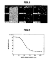
- FIG. 1a, 1b, and 1c are photomicrographs showing compositional distribution images of Nd, O, and F in a magnet body M1 manufactured in Example 1, respectively.
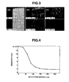
- FIG. 2 is a graph in which the resistivity of the magnet body M1 of Example 1 is plotted relative to a depth from the magnet surface.
- FIG. 3d, 3e, and 3f are photomicrographs showing compositional distribution images of Nd, O, and F in a magnet body M4 manufactured in Example 4, respectively.
- FIG. 4 is a graph in which the resistivity of the magnet body M4 of Example 4 is plotted relative to a depth from the magnet surface.
- The rare earth permanent magnet of the invention is in the form of a sintered magnet body obtained by causing E and fluorine atoms to be absorbed in a R-Fe-B sintered magnet body. The resultant magnet body has an alloy composition of the formula (1) or (2).


- Specifically, R is selected from among Sc, Y, La, Ce, Pr, Nd, Sm, Eu, Gd, Tb, Dy, Ho, Er, Yb, and Lu. Desirably, R contains Nd, Pr and Dy as a main component, the content of Nd and/or Pr being preferably at least 10 atom%, more preferably at least 50 atom% of R.
- E is at least one element selected from alkaline earth metal elements and rare earth elements, for example, Mg, Ca, Sr, Ba, La, Ce, Pr, Nd, Sm, Eu, Gd, Tb, Dy, Ho, Er, Yb, and Lu, preferably Mg, Ca, Pr, Nd, Tb, and Dy, more preferably Ca, Pr, Nd, and Dy.
- The amount (a) of R is 10 to 15 atom%, as recited above, and preferably 12 to 15 atom%. The amount (b) of E is 0.005 to 2 atom%, preferably 0.01 to 2 atom%, and more preferably 0.02 to 1.5 atom%.
- The amount (c) of T, which is Fe and/or Co, is preferably at least 60 atom%, and more preferably at least 70 atom%. Although cobalt can be omitted (i.e., 0 atom%), cobalt may be included in an amount of at least 1 atom%, preferably at least 3 atom%, more preferably at least 5 atom% for improving the temperature stability of remanence or other purposes.
- Preferably A, which is boron and/or carbon, contains at least 80 atom%, more preferably at least 85 atom% of boron. The amount (d) of A is 3 to 15 atom%, as recited above, preferably 4 to 12 atom%, and more preferably 5 to 8 atom%.
- The amount (e) of fluorine is 0.01 to 4 atom%, as recited above, preferably 0.02 to 3.5 atom%, and more preferably 0.05 to 3.5 atom%. At too low a fluorine content, an enhancement of coercive force is not observable. Too high a fluorine content alters the grain boundary phase, leading to a reduced coercive force.
- The amount (f) of oxygen is 0.04 to 4 atom%, as recited above, preferably 0.04 to 3.5 atom%, and more preferably 0.04 to 3 atom%.
- The amount (g) of other metal element M is 0.01 to 11 atom%, as recited above, preferably 0.01 to 8 atom%, and more preferably 0.02 to 5 atom%. The other metal element M may be present in an amount of at least 0.05 atom%, and especially at least 0.1 atom%.
- It is noted that the sintered magnet body has a center and a surface. In the invention, constituent element F is distributed in the sintered magnet body such that its concentration increases on the average from the center of the magnet body toward the surface of the magnet body. Specifically, the concentration of F is highest at the surface of the magnet body and gradually decreases toward the center of the magnet body. Fluorine may be absent at the magnet body center because the invention merely requires that the oxyfluoride of R and E, typically (R1-xEx)OF (wherein x is a number of 0 to 1) be present at grain boundaries in a grain boundary region that extends from the magnet body surface to a depth of at least 20 µm. While grain boundaries surround primary phase grains of (R, E)2 T14A tetragonal system within the sintered magnet body, the concentration of E/(R+E) contained in the grain boundaries is on the average higher than the concentration of E/(R+E) contained in the primary phase grains.
- In the permanent magnet of the invention, the oxyfluoride of (R,E) is present at grain boundaries in a grain boundary region that extends from the magnet body surface to a depth of at least 20 µm. In a preferred embodiment, particles of the oxyfluoride having an equivalent circle diameter of at least 1 µm is distributed in the grain boundary region at a population of at least 2,000 particles/mm2, more preferably at least 3,000 particles/mm2, most preferably 4,000 to 20,000 particles/mm2. The oxyfluoride is present in an area fraction of at least 1%, more preferably at least 2%, most preferably 2.5 to 10%. The number and area fraction of particles are determined by taking a compositional distribution image by electron probe microanalysis (EPMA), processing the image, and counting oxyfluoride particles having an equivalent circle diameter of at least 1 µm.
- The rare earth permanent magnet of the invention can be manufactured by feeding a powder containing E and F to the surface of an R-Fe-B sintered magnet body, and heat treating the packed magnet body. The R-Fe-B sintered magnet body, in turn, can be manufactured by a conventional process including crushing a mother alloy, milling, compacting and sintering.
- The mother alloy used herein contains R, T, A, and M. R is at least one element selected from rare earth elements inclusive of Sc and Y. R is typically selected from among Sc, Y, La, Ce, Pr, Nd, Sm, Eu, Gd, Tb, Dy, Ho, Er, Yb, and Lu. Desirably, R contains Nd, Pr and Dy as main components. These rare earth elements inclusive of Sc and Y are preferably present in an amount of 10 to 15 atom%, more preferably 12 to 15 atom% of the overall alloy. More desirably, R contains one or both of Nd and Pr in an amount of at least 10 atom%, especially at least 50 atom% of the entire R. T is one or both of Fe and Co, and Fe is preferably contained in an amount of at least 50 atom%, and more preferably at least 65 atom% of the overall alloy. A is one or both of boron and carbon, and boron is preferably contained in an amount of 2 to 15 atom%, and more preferably 3 to 8 atom% of the overall alloy. M is at least one element selected from the group consisting of A1, Cu, Zn, In, Si, P, S, Ti, V, Cr, Mn, Ni, Ga, Ge, Zr, Nb, Mo, Pd, Ag, Cd, Sn, Sb, Hf, Ta, and W. M may be contained in an amount of 0.01 to 11 atom%, and preferably 0.1 to 5 atom% of the overall alloy. The balance is composed of incidental impurities such as N and O.
- Mother alloy is typically prepared by melting metal or alloy feeds in vacuum or an inert gas atmosphere, typically argon atmosphere, and casting the melt into a flat mold or book mold or strip casting. A possible alternative is a so-called two-alloy process involving separately preparing an alloy approximate to the R2Fe14B compound composition constituting the primary phase of the relevant alloy and an R-rich alloy serving as a liquid phase aid at the sintering temperature, crushing, then weighing and mixing them. Notably, the alloy approximate to the primary phase composition is subjected to homogenizing treatment, if necessary, for the purpose of increasing the amount of the R2Fe14B compound phase, since α-Fe is likely to be left depending on the cooling rate during casting and the alloy composition. The homogenizing treatment is a heat treatment at 700 to 1,200°C for at least one hour in vacuum or in an Ar atmosphere. To the R-rich alloy serving as a liquid phase aid, a so-called melt quenching or strip casting technique is applicable as well as the above-described casting technique.
- The mother alloy is generally crushed to a size of 0.05 to 3 mm, preferably 0.05 to 1.5 mm. The crushing step uses a Brown mill or hydriding pulverization, with the hydriding pulverization being preferred for those alloys as strip cast. The coarse powder is then finely divided to a size of generally 0.2 to 30 µm, preferably 0.5 to 20 µm, for example, by a jet mill using nitrogen under pressure. The oxygen content of the sintered body can be controlled by admixing a minor amount of oxygen with the pressurized nitrogen at this point. The oxygen content of the final sintered body, which is given as the oxygen introduced during the preparation of the ingot plus the oxygen taken up during transition from the fine powder to the sintered body, is preferably 0.04 to 4 atom%, more preferably 0.04 to 3.5 atom%.
- The fine powder is then compacted under a magnetic field on a compression molding machine and placed in a sintering furnace. Sintering is effected in vacuum or in an inert gas atmosphere usually at a temperature of 900 to 1,250°C, preferably 1,000 to 1,100°C. The thus sintered magnet contains 60 to 99 vol%, preferably 80 to 98 vol% of the tetragonal R2Fe14B compound as a primary phase, the balance being 0.5 to 20 vol% of an R-rich phase, 0 to 10 vol% of a B-rich phase, 0.1 to 10 vol% of R oxide, and at least one of carbides, nitrides and hydroxides of incidental impurities or a mixture or composite thereof.
- The sintered block is machined into a magnet body of a predetermined shape, after which E and fluorine atoms are absorbed and infiltrated in the magnet body in order to impart the characteristic physical structure that the electric resistance of a surface layer is higher than in the interior.
- Referring to a typical treatment, a powder containing E and fluorine atoms is disposed on the surface of the sintered magnet body. The magnet body packed with the powder is heat treated in vacuum or in an atmosphere of inert gas such as Ar or He at a temperature of not higher than the sintering temperature (referred to as Ts), preferably 200°C to (Ts-5)°C, especially 250°C to (Ts-10)°C for about 0.5 to 100 hours, preferably about 1 to 50 hours. Through the heat treatment, E and fluorine are infiltrated into the magnet from the surface and the R oxide within the sintered magnet body reacts with fluorine to make a chemical change into an oxyfluoride.
- The oxyfluoride of R within the magnet is typically ROF, although it generally denotes oxyfluorides containing R, oxygen and fluorine that can achieve the effect of the invention including ROmFn (wherein m and n are positive numbers) and modified or stabilized forms of ROmFn wherein part of R is replaced by a metal element.
- The amount of fluorine absorbed in the magnet body at this point varies with the composition and particle size of the powder used, the proportion of the powder occupying the magnet surface-surrounding space during the heat treatment, the specific surface area of the magnet, the temperature and time of the heat treatment although the absorbed fluorine amount is preferably 0.01 to 4 atom%. The absorbed fluorine amount is further preferably 0.02 to 3.5 atom%, especially 0.05 to 3.5 atom% in order that particles of the oxyfluoride having an equivalent circle diameter of at least 1 µm be distributed along the grain boundaries at a population of at least 2,000 particles/mm2, more preferably at least 3,000 particles/mm2. For absorption, fluorine is fed to the surface of the magnet body in an amount of preferably 0.03 to 30 mg/cm2, more preferably 0.15 to 15 mg/cm2 of the surface.
- As described above, in a region that extends from the magnet body surface to a depth of at least 20 µm, particles of the oxyfluoride having an equivalent circle diameter of at least 1 µm are distributed at grain boundaries at a population of at least 2,000 particles/mm2. The depth from the magnet body surface of the region where the oxyfluoride is present can be controlled by the concentration of oxygen in the magnet body. In this regard, it is recommended that the concentration of oxygen contained in the magnet body be 0.04 to 4 atom%, more preferably 0.04 to 3.5 atom%, most preferably 0.04 to 3 atom%. If the depth from the magnet body surface of the region where the oxyfluoride is present, the particle diameter of the oxyfluoride, and the population of the oxyfluoride are outside the above-specified ranges, undesirably the electric resistivity of the magnet body surface layer could not be effectively increased.
- Through the heat treatment, the E component is also enriched adjacent to grain boundaries. The total amount of E component absorbed in the magnet body is preferably 0.005 to 2 atom%, more preferably 0.01 to 2 atom%, even more preferably 0.02 to 1.5 atom%. For absorption, the E component is fed to the surface of the magnet body in a total amount of preferably 0.07 to 70 mg/cm2, more preferably 0.35 to 35 mg/cm2 of the surface.
- The surface layer or region of the magnet body where the oxyfluoride is present in the above-described range has an electric resistivity of preferably at least 5.0×10⁻⁶ Ωm, more preferably at least 1.0x1-50 Ωm. A central region of the magnet body has a resistivity of the order of 2x10⁻⁶ Ωm. Preferably the resistivity of the surface region is higher than that of the central region by a factor of at least 2.5, especially at least 5. A resistivity ratio outside that range has less effect in reducing the eddy current effectively while preventing the magnet body from generating heat.
- In permanent magnets as proposed herein, we find that eddy current loss in the surface region can be reduced to about one half or less as compared with prior art magnets.
- The permanent magnet material containing R oxyfluoride of the invention has a graded function that resistivity varies from the surface toward the interior and can be used as a high-performance rare earth permanent magnet featuring the restrained generation of eddy current in a magnetic circuit, especially as a magnet for IPM motors.
- Methods of making such magnets, as disclosed herein, are an aspect of the invention.
- Examples of the present invention are given below by way of illustration and not by way of limitation.
- An alloy in thin plate form was prepared by using Nd, Co, A1, and Fe metals of at least 99 wt% purity and ferroboron, weighing predetermined amounts of them, high-frequency melting them in an Ar atmosphere, and casting the melt onto a single chill roll of copper (strip casting technique). The alloy consisted of 12.8 atom% Nd, 1.0 atom% Co, 0.5 atom% A1, 5.8 atom% B, and the balance of Fe. It is designated alloy A. The alloy A was ground to a size of under 30 mesh by the hydriding technique including the steps of hydriding the alloy, and heating up to 500°C for partial dehydriding while evacuating the chamber to vacuum.
- Separately, an alloy was prepared by using Nd, Dy, Fe, Co, A1, and Cu metals of at least 99 wt% purity and ferroboron, weighing predetermined amounts of them, high-frequency melting them in an Ar atmosphere, and casting the melt in a mold. The alloy consisted of 20 atom% Nd, 10 atom% Dy, 24 atom% Fe, 6 atom% B, 1 atom% A1, 2 atom% Cu, and the balance of Co. It is designated alloy B. The alloy B was crushed to a size of under 30 mesh in a nitrogen atmosphere on a Brown mill.
- Subsequently, the powders of alloys A and B were weighed in an amount of 93 wt% and 7 wt% and mixed for 30 minutes on a nitrogen-blanketed V blender. On a jet mill using nitrogen gas under pressure, the powder mixture was finely divided into a powder with a mass base median diameter of 4 µm. The fine powder was oriented in a magnetic field of 15 kOe under a nitrogen atmosphere and compacted under a pressure of about 1 ton/cm2. The compact was then placed in a sintering furnace with an Ar atmosphere where it was sintered at 1,060°C for 2 hours, obtaining a magnet block. The foregoing steps were performed in a low oxygen atmosphere so that the resulting magnet block had an oxygen concentration of 0.81 atom%. Using a diamond cutter, the magnet block was machined on all the surfaces to dimensions of 50 mm x 50 mm x 5 mm. The magnet body was successively washed with alkaline solution, deionized water, aqueous acid and deionized water, and dried.
- Next, neodymium fluoride powder having an average particle size of 10 µm was mixed with ethanol in a weight fraction of 50% to form a slurry. The magnet body was immersed in the slurry for 1 minute while sonicating the slurry, taken up and immediately dried with hot air. The amount of neodymium fluoride fed was 0.8 mg/cm2. Thereafter, the packed magnet body was subjected to absorptive treatment in an Ar atmosphere at 800°C for 10 hours and then aging treatment at 500°C for 1 hour and quenched, obtaining a magnet body within the scope of the invention. This magnet body is designated M1. For comparison purposes, a magnet body was similarly prepared by effecting heat treatment without the neodymium fluoride packing. This is designated P1.
- The magnet bodies M1 and P1 were measured for magnetic properties (remanence Br, coercive force Hcj), with the results shown in Table 1. The compositions of the magnets are shown in Table 2. The magnet M1 of the invention exhibited substantially equal magnetic properties as compared with the magnet body P1 having undergone heat treatment without the neodymium fluoride package.
- Subsequently, the magnet bodies M1 and P1 were magnetized, sealed with a heat insulating material, and mounted in a solenoid coil. While the coil was actuated at 1,000 kHz to generate an alternating magnetic field of 12 kA/m, the temperature of the magnet body was monitored to determine a change of temperature with time, from which an eddy current loss was computed. The results are also shown in Table 1. The eddy current loss of the inventive magnet body M1 is less than one half of the loss of the comparative magnet body P1.
- The surface layer of magnet body M1 was analyzed by electron probe microanalysis (EPMA), with its compositional distribution images of Nd, O and F being shown in FIGS. 1a, 1b and 1c. A number of NdOF particles were distributed in the surface layer. In this region, those NdOF particles having an equivalent circle diameter of at least 1 µm had a population of 4,500 particles/mm2 and an area fraction of 3.8%.
- The magnet bodies M1 and P1 were machined into a rod of 1 mm x 1 mm x 10 mm. At this time, five of the magnet surfaces were machined so that one magnet surface was left intact after the machining. The non-machined surface (1×10 mm) of rod M1 was wet polished with #180 abrasive paper and mirror polished with #1000 to #4000 abrasive papers while resistivity was measured on that surface. FIG. 2 is a graph showing the resistivity versus the thickness of a surface layer abraded by polishing. At a depth of at least 200 µm from the magnet body surface, the resistivity becomes as low as in prior art magnets. It is demonstrated that the magnet body M1 has a higher resistivity at a position nearer to the surface layer, which leads to a reduced eddy current loss. The data prove that by dispersing oxyfluoride only in a surface layer, a permanent magnet having a reduced eddy current loss is obtainable.
- An alloy in thin plate form was prepared by using Nd, Co, A1, and Fe metals of at least 99 wt% purity and ferroboron, weighing predetermined amounts of them, high-frequency melting them in an Ar atmosphere, and casting the melt onto a single chill roll of copper (strip casting technique). The alloy consisted of 12.8 atom% Nd, 1.0 atom% Co, 0.5 atom% A1, 5.8 atom% B, and the balance of Fe. It is designated alloy A. The alloy A was ground to a size of under 30 mesh by the hydriding technique including the steps of hydriding the alloy, and heating up to 500°C for partial dehydriding while evacuating the chamber to vacuum.
- Separately, an alloy was prepared by using Nd, Dy, Fe, Co, A1, and Cu metals of at least 99 wt% purity and ferroboron, weighing predetermined amounts of them, high-frequency melting them in an Ar atmosphere, and casting the melt in a mold. The alloy consisted of 20 atom% Nd, 10 atom% Dy, 24 atom% Fe, 6 atom% B, 1 atom% Al, 2 atom% Cu, and the balance of Co. It is designated alloy B. The alloy B was crushed to a size of under 30 mesh in a nitrogen atmosphere on a Brown mill.
- Subsequently, the powders of alloys A and B were weighed on an amount of 93 wt% and 7 wt% and mixed for 30 minutes in a nitrogen-blanketed V blender. On a jet mill using nitrogen gas under pressure, the powder mixture was finely divided into a powder with a mass base median diameter of 4 µm. The fine powder was oriented in a magnetic field of 15 kOe under a nitrogen atmosphere and compacted under a pressure of about 1 ton/cm2. The compact was then placed in a sintering furnace with an Ar atmosphere where it was sintered at 1,060°C for 2 hours, obtaining a magnet block. The foregoing steps were performed in a low oxygen atmosphere so that the resulting magnet block had an oxygen concentration of 0.73 atom%. Using a diamond cutter, the magnet block was machined on all the surfaces to dimensions of 50 mm x 50 mm x 5 mm. The magnet body was successively washed with alkaline solution, deionized water, aqueous acid and deionized water, and dried.
- Next, dysprosium fluoride powder having an average particle size of 5 µm was mixed with ethanol in a weight fraction of 50% to form a slurry. The magnet body was immersed in the slurry for 1 minute while sonicating the slurry, taken up and immediately dried with hot air. The amount of dysprosium fluoride fed was 1.1 mg/cm2. Thereafter, the packed magnet body was subjected to absorptive treatment in an Ar atmosphere at 900°C for 1 hour and then aging treatment at 500°C for 1 hour and quenched, obtaining a magnet body within the scope of the invention. This magnet body is designated M2. For comparison purposes, a magnet body was similarly prepared by effecting heat treatment without the dysprosium fluoride package. This is designated P2.
- The magnet bodies M2 and P2 were measured for magnetic properties (Br, Hcj), with the results shown in Table 1. The compositions of the magnets are shown in Table 2. The magnet M2 of the invention exhibited a substantially equal remanence and a higher coercive force as compared with the magnet body P2 having undergone heat treatment without the dysprosium fluoride package. Subsequently, the eddy current loss was measured by the same procedure as in Example 1, with the results also shown in Table 1. The eddy current loss (2.41 W) of the inventive magnet body M2 is less than one half of the loss (6.86 W) of the comparative magnet body P2. The surface layer of magnet body M2 was analyzed by EPMA to determine the concentration distributions of elements, indicating the presence of numerous ROF particles in the same form as in Example 1.
- An alloy in thin plate form was prepared by using Nd, Co, A1, and Fe metals of at least 99 wt% purity and ferroboron, weighing predetermined amounts of them, high-frequency melting them in an Ar atmosphere, and casting the melt onto a single chill roll of copper (strip casting technique). The alloy consisted of 13.5 atom% Nd, 1.0 atom% Co, 0.5 atom% A1, 5.8 atom% B, and the balance of Fe. The alloy was ground to a size of under 30 mesh by the hydriding technique including the steps of hydriding the alloy, and heating up to 500°C for partial dehydriding while evacuating the chamber to vacuum.
- On a jet mill using nitrogen gas under pressure, the coarse powder was finely divided into a powder with a mass base median diameter of 4 µm. The fine powder was oriented in a magnetic field of 15 kOe under a nitrogen atmosphere and compacted under a pressure of about 1 ton/cm2. The compact was then placed in a sintering furnace with an Ar atmosphere where it was sintered at 1,060°C for 2 hours, obtaining a magnet block. The foregoing steps were performed in a low oxygen atmosphere so that the resulting magnet block had an oxygen concentration of 0.89 atom%. Using a diamond cutter, the magnet block was machined on all the surfaces to dimensions of 50 mm x 50 mm x 5 mm.
- Next, praseodymium fluoride powder having an average particle size of 5 µm was mixed with ethanol in a weight fraction of 50% to form a slurry. The magnet body was immersed in the slurry for 1 minute while sonicating the slurry, taken up and immediately dried with hot air. The amount of praseodymium fluoride fed was 0.9 mg/cm2. Thereafter, the packed magnet body was subjected to absorptive treatment in an Ar atmosphere at 900°C for 5 hours and then aging treatment at 500°C for 1 hour and quenched, obtaining a magnet body within the scope of the invention. This magnet body is designated M3. For comparison purposes, a magnet body was similarly prepared by effecting heat treatment without the praseodymium fluoride package. This is designated P3.
- The magnet bodies M3 and P3 were measured for magnetic properties (Br, Hcj), with the results shown in Table 1. The compositions of the magnets are shown in Table 2. The magnet M3 of the invention exhibited a substantially equal remanence and a higher coercive force as compared with the magnet body P3 having undergone heat treatment without the praseodymium fluoride package. Subsequently, the eddy current loss was measured by the same procedure as in Example 1, with the results also shown in Table 1. The eddy current loss of the inventive magnet body M3 is less than one half of the loss of the comparative magnet body P3. The surface layer of magnet body M3 was analyzed by EPMA to determine the concentration distributions of elements, indicating the presence of numerous ROF particles in the same form as in Example 1.
- An alloy in thin plate form was prepared by using Nd, Co, A1, and Fe metals of at least 99 wt% purity and ferroboron, weighing predetermined amounts of them, high-frequency melting them in an Ar atmosphere, and casting the melt onto a single chill roll of copper (strip casting technique). The alloy consisted of 12.8 atom% Nd, 1.0 atom% Co, 0.5 atom% A1, 5.8 atom% B, and the balance of Fe. It is designated alloy A. The alloy A was ground to a size of under 30 mesh by the hydriding technique including the steps of hydriding the alloy, and heating up to 500°C for partial dehydriding while evacuating the chamber to vacuum.
- Separately, an alloy was prepared by using Nd, Dy, Fe, Co, A1, and Cu metals of at least 99 wt% purity and ferroboron, weighing predetermined amounts of them, high-frequency melting them in an Ar atmosphere, and casting the melt in a mold. The alloy consisted of 20 atom% Nd, 10 atom% Dy, 24 atom% Fe, 6 atom% B, 1 atom% A1, 2 atom% Cu, and the balance of Co. It is designated alloy B. The alloy B was crushed to a size of under 30 mesh in a nitrogen atmosphere on a Brown mill.
- Subsequently, the powders of alloys A and B were weighed in an amount of 88 wt% and 12 wt% and mixed for 30 minutes on a nitrogen-blanketed V blender. On a jet mill using nitrogen gas under pressure, the powder mixture was finely divided into a powder with a mass base median diameter of 5.5 µm. The fine powder was oriented in a magnetic field of 15 kOe under a nitrogen atmosphere and compacted under a pressure of about 1 ton/cm2. The compact was then placed in a sintering furnace with an Ar atmosphere where it was sintered at 1,060°C for 2 hours, obtaining a magnet block. The foregoing steps were performed in an atmosphere having an oxygen concentration of 21% so that the resulting magnet block had an oxygen concentration of 2.4 atom%. Using a diamond cutter, the magnet block was machined on all the surfaces to dimensions of 50 mm x 50 mm x 5 mm. The magnet body was successively washed with alkaline solution, deionized water, aqueous acid and deionized water, and dried.
- Next, dysprosium fluoride powder having an average particle size of 5 µm was mixed with ethanol in a weight fraction of 50% to form a slurry. The magnet body was immersed in the slurry for 1 minute while sonicating the slurry, taken up and immediately dried with hot air. The amount of dysprosium fluoride fed was 1.4 mg/cm2. Thereafter, the packed magnet body was subjected to absorptive treatment in an Ar atmosphere at 900°C for 1 hour and then aging treatment at 500°C for 1 hour and quenched, obtaining a magnet body within the scope of the invention. This magnet body is designated M4. For comparison purposes, a magnet body was similarly prepared by effecting heat treatment without the dysprosium fluoride package. This is designated P4.
- The magnet bodies M4 and P4 were measured for magnetic properties (Br, Hcj), with the results shown in Table 1. The compositions of the magnets are shown in Table 2. The magnet M4 of the invention exhibited a substantially equal remanence and a higher coercive force as compared with the magnet body P4 having undergone heat treatment without the dysprosium fluoride package. Subsequently, the eddy current loss was measured by the same procedure as in Example 1, with the results also shown in Table 1. The eddy current loss (2.25 W) of the inventive magnet body M4 is less than one half of the loss (5.53 W) of the comparative magnet body P4.
- The surface layer of magnet body M4 was analyzed by EPMA, with its compositional distribution images of Nd, O and F being shown in FIGS. 3d, 3e and 3f. A number of NdOF particles were distributed in the surface layer. In this region, they had a population of 3,200 particles/mm2 and an area fraction of 8.5%. The resistivity of magnet body M4 was measured as in Example 1. FIG. 4 is a graph showing the resistivity versus the thickness of a surface layer abraded by polishing. At a depth of at least 170 µm from the magnet body surface, the resistivity becomes as low as in prior art magnets.
- An alloy in thin plate form was prepared by using Nd, Co, A1, and Fe metals of at least 99 wt% purity and ferroboron, weighing predetermined amounts of them, high-frequency melting them in an Ar atmosphere, and casting the melt onto a single chill roll of copper (strip casting technique). The alloy consisted of 12.8 atom% Nd, 1.0 atom% Co, 0.5 atom% A1, 5.8 atom% B, and the balance of Fe. It is designated alloy A. The alloy A was ground to a size of under 30 mesh by the hydriding technique including the steps of hydriding the alloy, and heating up to 500°C for partial dehydriding while evacuating the chamber to vacuum.
- Separately, an alloy was prepared by using Nd, Dy, Fe, Co, Al, and Cu metals of at least 99 wt% purity and ferroboron, weighing predetermined amounts of them, high-frequency melting them in an Ar atmosphere, and casting the melt in a mold. The alloy consisted of 20 atom% Nd, 10 atom% Dy, 24 atom% Fe, 6 atom% B, 1 atom% A1, 2 atom% Cu, and the balance of Co. It is designated alloy B. The alloy B was crushed to a size of under 30 mesh in a nitrogen atmosphere on a Brown mill.
- Subsequently, the powders of alloys A and B were weighed in an amount of 93 wt% and 7 wt% and mixed for 30 minutes on a nitrogen-blanketed V blender. On a jet mill using nitrogen gas under pressure, the powder mixture was finely divided into a powder with a mass base median diameter of 4 µm. The fine powder was oriented in a magnetic field of 15 kOe under a nitrogen atmosphere and compacted under a pressure of about 1 ton/cm2. The compact was then placed in a sintering furnace with an Ar atmosphere where it was sintered at 1,060°C for 2 hours, obtaining a magnet block. The foregoing steps were performed in a low oxygen atmosphere so that the resulting magnet block had an oxygen concentration of 0.73 atom%. Using a diamond cutter, the magnet block was machined on all the surfaces to dimensions of 50 mm x 50 mm x 5 mm. The magnet body was successively washed with alkaline solution, deionized water, aqueous acid and deionized water, and dried.
- Next, calcium fluoride powder having an average particle size of 10 µm was mixed with ethanol in a weight fraction of 50% to form a slurry. The magnet body was immersed in the slurry for 1 minute while sonicating the slurry, taken up and immediately dried with hot air. The amount of calcium fluoride fed was 0.7 mg/cm2. Thereafter, the packed magnet body was subjected to absorptive treatment in an Ar atmosphere at 900°C for 1 hour and then aging treatment at 500°C for 1 hour and quenched, obtaining a magnet body within the scope of the invention. This magnet body is designated M5. For comparison purposes, a magnet body was similarly prepared by effecting heat treatment without the calcium fluoride package. This is designated P5.
- The magnet bodies M5 and P5 were measured for magnetic properties (Br, Hcj), with the results shown in Table 1. The compositions of the magnets are shown in Table 2. The magnet M5 of the invention exhibited a substantially equal remanence and coercive force as compared with the magnet body P5 having undergone heat treatment without the calcium fluoride package. Subsequently, the eddy current loss was measured by the same procedure as in Example 1, with the results also shown in Table 1. The eddy current loss (2.44 W) of the inventive magnet body M5 is less than one half of the loss (6.95 W) of the comparative magnet body P5. The surface layer of magnet body M5 was analyzed by EPMA to determine the concentration distributions of elements, indicating the presence of numerous ROF particles in the same form as in Example 1.
Table 1 Br (T) Hcj (kA/m) Eddy current loss (W) Example 1 M1 1.435 960 2.53 Example 2 M2 1.425 1480 2.41 Example 3 M3 1.425 1120 2.64 Example 4 M4 1.338 1340 2.25 Example 5 M5 1.398 960 2.44 Comparative Example 1 P1 1.440 960 6.75 Comparative Example 2 P2 1.420 1080 6.86 Comparative Example 3 P3 1.420 1080 6.91 Comparative Example 4 P4 1.341 1260 5.53 Comparative Example 5 P5 1.410 1100 6.95 Table 2 R [at.%] E [at.%] T [at.%] A [at.%] F [at.%] O [at.%] M** [at.%] Example 1 M1 13.955* 13.260* 78.754 5.827 0.181 0.613 0.677 Example 2 M2 13.933* 0.771* 78.894 5.837 0.253 0.409 0.678 Example 3 M3 13.257 0.230 78.957 5.782 0.598 0.730 0.498 Example 4 M4 14.650* 1.259* 77.192 5.791 0.279 1.318 0.795 Example 5 M5 13.828 0.042 78.768 5.828 0.122 0.744 0.677 Comparative Example 1 P1 13.928* 13.220* 78.941 5.841 0.000 0.615 0.678 Comparative Example 2 P2 13.895* 0.688* 79.154 5.857 0.000 0.415 0.680 Comparative Example 3 P3 13.362 0.000 79.582 5.828 0.000 0.731 0.502 Comparative Example 4 P4 14.612* 1.169* 77.477 5.812 0.000 1.317 0.798 Comparative Example 5 P5 13.849 0.000 78.890 5.837 0.000 0.751 0.678 * Total amount of common element contained as R and E in magnet material. ** Total amount of element as M in formula (1) or (2). - Analytical values of rare earth elements and alkaline earth metal elements were determined by entirely dissolving samples (prepared as in Examples and Comparative Examples) in aqua regia, and effecting measurement by inductively coupled plasma (ICP), analytical values of oxygen determined by inert gas fusion/infrared absorption spectroscopy, and analytical values of fluorine determined by steam distillation/Alfusone colorimetry.
- It will of course be understood that in numerical ranges given herein, the technical reasons for the upper and the lower limit naturally differ so that the upper and lower limits constitute independent technical criteria.
- Since E used in the surface treatment can in principle be compositionally the same as the R used in the magnet body (remembering that either or both of E and R can be a mixture of different elements, and that R usually is such a mixture), it should be noted that in such a case the concentration E/(R+E) does not fall to be defined in the product per se, although it is still meaningful as a process parameter.
Claims (5)
- A rare earth permanent magnet in the form of a sintered magnet body having an alloy composition of formula (1) or (2):


wherein R is at least one element selected from rare earth elements, Sc and Y, and E is at least one element selected from alkaline earth metal elements and rare earth elements, R and E may comprise one or more elements in common, the sintered magnet body has the alloy composition of formula (1) when R and E do not contain the same element(s) and has the alloy composition of formula (2) when R and E contain the same element(s), T is one or both of iron and cobalt, A is one or both of boron and carbon, F is fluorine, O is oxygen, and M is at least one element selected from Al, Cu, Zn, In, Si, P, S, Ti, V, Cr, Mn, Ni, Ga, Ge, Zr, Nb, Mo, Pd, Ag, Cd, Sn, Sb, Hf, Ta, and W, indices a to g indicating atom percents of the corresponding elements in the alloy have values satisfying: 10 ≤ a ≤ 15 and 0.005 ≤ b ≤ 2 in case of formula (1) or 10.005 ≤ a+b ≤ 17 in case of formula (2), 3 ≤ d s 15, 0.01 ≤ e ≤ 4, 0.04 ≤ f s 4, 0.01 ≤ g ≤ 11, the balance being c, said magnet body having a center and a surface and being obtainable by causing E and fluorine atoms to be absorbed in a R-Fe-B sintered magnet body from its surface,
wherein constituent element F is distributed such that its concentration increases on the average from the center toward the surface of the magnet body, grain boundaries surround primary phase grains of (R,E)2T14A tetragonal system within the sintered magnet body, the E concentration E/(R+E) contained in the grain boundaries is on the average higher than the E concentration E/(R+E) contained in the primary phase grains, the oxyfluoride of (R,E) is present at grain boundaries in a grain boundary region that extends from the magnet body surface to a depth of at least 20 µm, particles of said oxyfluoride having an equivalent circle diameter of at least 1 µm are distributed in said grain boundary region at a population of at least 2,000 particles/mm2, said oxyfluoride is present in an area fraction of at least 1%, and said magnet body includes a surface layer having a higher electric resistance than the magnet body interior. - The rare earth permanent magnet of claim 1 wherein R comprises at least 10 atom% of Nd and/or Pr.
- The rare earth permanent magnet of claim 1 or 2
wherein T comprises at least 60 atom% of iron. - The rare earth permanent magnet of any one of claims 1 to 3 wherein A comprises at least 80 atom% of boron.
- A method of making a rare earth permanent magnet having a surface layer with a higher electric resistance than the interior, having a concentration of F increasing towards the surface and oxyfluoride present in a grain boundary region extending to a depth of at least 20 µm, as defined in claim 1, comprising providing an R-Fe-B sintered magnet body and heat treating it with its surface exposed to atoms of E and F, e.g. fluoride of E.
Priority Applications (1)
| Application Number | Priority Date | Filing Date | Title |
|---|---|---|---|
| EP10009415A EP2267729A3 (en) | 2005-03-23 | 2006-02-01 | Functionally graded rare earth permanent magnet |
Applications Claiming Priority (1)
| Application Number | Priority Date | Filing Date | Title |
|---|---|---|---|
| JP2005084358 | 2005-03-23 |
Related Child Applications (1)
| Application Number | Title | Priority Date | Filing Date |
|---|---|---|---|
| EP10009415.0 Division-Into | 2010-09-10 |
Publications (3)
| Publication Number | Publication Date |
|---|---|
| EP1705670A2 true EP1705670A2 (en) | 2006-09-27 |
| EP1705670A3 EP1705670A3 (en) | 2008-02-13 |
| EP1705670B1 EP1705670B1 (en) | 2012-03-28 |
Family
ID=36607273
Family Applications (2)
| Application Number | Title | Priority Date | Filing Date |
|---|---|---|---|
| EP10009415A Withdrawn EP2267729A3 (en) | 2005-03-23 | 2006-02-01 | Functionally graded rare earth permanent magnet |
| EP06250544A Active EP1705670B1 (en) | 2005-03-23 | 2006-02-01 | Functionally graded rare earth permanent magnet |
Family Applications Before (1)
| Application Number | Title | Priority Date | Filing Date |
|---|---|---|---|
| EP10009415A Withdrawn EP2267729A3 (en) | 2005-03-23 | 2006-02-01 | Functionally graded rare earth permanent magnet |
Country Status (8)
| Country | Link |
|---|---|
| US (1) | US7488395B2 (en) |
| EP (2) | EP2267729A3 (en) |
| KR (1) | KR101147385B1 (en) |
| CN (1) | CN101030467B (en) |
| BR (1) | BRPI0600209B1 (en) |
| MY (1) | MY141999A (en) |
| RU (1) | RU2359352C2 (en) |
| TW (1) | TWI413137B (en) |
Cited By (7)
| Publication number | Priority date | Publication date | Assignee | Title |
|---|---|---|---|---|
| EP1923893A1 (en) * | 2006-11-17 | 2008-05-21 | Shin-Etsu Chemical Co., Ltd. | Method for preparing rare earth permanent magnet |
| US7955443B2 (en) | 2006-04-14 | 2011-06-07 | Shin-Etsu Chemical Co., Ltd. | Method for preparing rare earth permanent magnet material |
| US8211327B2 (en) | 2004-10-19 | 2012-07-03 | Shin-Etsu Chemical Co., Ltd. | Preparation of rare earth permanent magnet material |
| US8231740B2 (en) | 2006-04-14 | 2012-07-31 | Shin-Etsu Chemical Co., Ltd. | Method for preparing rare earth permanent magnet material |
| US8487487B2 (en) | 2008-07-15 | 2013-07-16 | Ethicon Endo-Surgery, Inc. | Magnetostrictive actuator of a medical ultrasound transducer assembly, and a medical ultrasound handpiece and a medical ultrasound system having such actuator |
| CN113046619A (en) * | 2021-03-13 | 2021-06-29 | 湖南大学 | Large-expansion-amount rare earth giant magnetostrictive material and preparation method thereof |
| CN115862988A (en) * | 2022-12-20 | 2023-03-28 | 东莞金坤新材料股份有限公司 | Antirust neodymium iron boron permanent magnet material and manufacturing method thereof |
Families Citing this family (38)
| Publication number | Priority date | Publication date | Assignee | Title |
|---|---|---|---|---|
| US7909061B2 (en) | 2005-06-17 | 2011-03-22 | Masco Corporation Of Indiana | Magnetic coupling for sprayheads |
| US7753079B2 (en) | 2005-06-17 | 2010-07-13 | Masco Corporation Of Indiana | Magnetic coupling for sprayheads |
| US9315975B2 (en) | 2005-06-17 | 2016-04-19 | Delta Faucet Company | Magnetic coupling for sprayheads |
| US7559996B2 (en) | 2005-07-22 | 2009-07-14 | Shin-Etsu Chemical Co., Ltd. | Rare earth permanent magnet, making method, and permanent magnet rotary machine |
| JP2007116088A (en) * | 2005-09-26 | 2007-05-10 | Hitachi Ltd | Magnetic material, magnet and rotating machine |
| US7988795B2 (en) * | 2005-12-02 | 2011-08-02 | Shin-Etsu Chemical Co., Ltd. | R-T-B—C rare earth sintered magnet and making method |
| EP2899726B1 (en) * | 2006-03-03 | 2018-02-21 | Hitachi Metals, Ltd. | R-fe-b rare earth sintered magnet |
| JP4605396B2 (en) * | 2006-04-14 | 2011-01-05 | 信越化学工業株式会社 | Method for producing rare earth permanent magnet material |
| JP4753030B2 (en) * | 2006-04-14 | 2011-08-17 | 信越化学工業株式会社 | Method for producing rare earth permanent magnet material |
| JP4737431B2 (en) | 2006-08-30 | 2011-08-03 | 信越化学工業株式会社 | Permanent magnet rotating machine |
| US8421292B2 (en) * | 2007-03-27 | 2013-04-16 | Hitachi Metals, Ltd. | Permanent magnet motor having composite magnets and manufacturing method thereof |
| CN101682222A (en) * | 2007-05-28 | 2010-03-24 | 丰田自动车株式会社 | rotor for magnet-embedded motor and magnet-embedded motor |
| JP4576418B2 (en) * | 2007-12-10 | 2010-11-10 | 株式会社日立製作所 | High resistance dust core |
| JP4672030B2 (en) * | 2008-01-31 | 2011-04-20 | 日立オートモティブシステムズ株式会社 | Sintered magnet and rotating machine using the same |
| JP2010022147A (en) * | 2008-07-11 | 2010-01-28 | Hitachi Ltd | Sintered magnet motor |
| JP4896104B2 (en) * | 2008-09-29 | 2012-03-14 | 株式会社日立製作所 | Sintered magnet and rotating machine using the same |
| US8627844B2 (en) * | 2009-10-30 | 2014-01-14 | Masco Corporation Of Indiana | Magnetic escutcheon mounting assembly |
| US8567430B2 (en) | 2009-10-30 | 2013-10-29 | Masco Corporation Of Indiana | Magnetic coupling for faucet handle |
| US20110200839A1 (en) * | 2010-02-17 | 2011-08-18 | Melania Marinescu | Rare Earth Laminated, Composite Magnets With Increased Electrical Resistivity |
| CN102483980B (en) | 2010-03-04 | 2016-09-07 | Tdk株式会社 | Rare-earth sintering magnet and motor |
| JP5494056B2 (en) * | 2010-03-16 | 2014-05-14 | Tdk株式会社 | Rare earth sintered magnet, rotating machine and reciprocating motor |
| US8823478B2 (en) | 2010-03-30 | 2014-09-02 | Tdk Corporation | Rare earth sintered magnet, method for producing same, motor and automobile |
| CN101859639B (en) * | 2010-07-06 | 2013-03-27 | 烟台正海磁性材料股份有限公司 | R-Fe-B series magnet of gradient resistance and production method thereof |
| RU2538272C2 (en) * | 2010-09-15 | 2015-01-10 | Тойота Дзидося Кабусики Кайся | Manufacturing method of magnets from rare-earth metals |
| US9064625B2 (en) | 2011-08-09 | 2015-06-23 | Electron Energy Corporation | Methods for sequentially laminating rare earth permanent magnets with suflide-based dielectric layer |
| US9147524B2 (en) | 2011-08-30 | 2015-09-29 | General Electric Company | High resistivity magnetic materials |
| CN103377789B (en) * | 2012-05-17 | 2017-02-22 | 京磁材料科技股份有限公司 | Rare-earth permanent magnet and manufacturing method thereof |
| JP5868500B2 (en) * | 2012-05-30 | 2016-02-24 | 株式会社日立製作所 | Sintered magnet and manufacturing method thereof |
| US20150162117A1 (en) * | 2012-06-13 | 2015-06-11 | Hitachi, Ltd. | Sintered magnet and production process therefor |
| US9181685B2 (en) | 2012-07-27 | 2015-11-10 | Kohler Co. | Magnetic docking faucet |
| US9284723B2 (en) | 2012-07-27 | 2016-03-15 | Kohler Co. | Magnetic docking faucet |
| CN104464996B (en) * | 2014-12-11 | 2016-11-09 | 青岛申达众创技术服务有限公司 | A kind of sintered Nd-Fe-B permanent magnetic material and preparation method thereof |
| JP6927906B2 (en) * | 2017-09-29 | 2021-09-01 | トヨタ自動車株式会社 | Rare earth magnet |
| CN109783869B (en) * | 2018-12-17 | 2020-08-21 | 中国原子能科学研究院 | Method for predicting heat-aging grain boundary P segregation of welding line of reactor pressure vessel |
| CN110176351A (en) * | 2019-06-24 | 2019-08-27 | 中钢集团安徽天源科技股份有限公司 | A kind of preparation method of high efficiency motor neodymium iron boron magnetic body |
| CN110415908B (en) * | 2019-06-26 | 2021-08-03 | 宁波金轮磁材技术有限公司 | Rare earth neodymium iron boron permanent magnet material and preparation method thereof |
| CN112086256B (en) * | 2020-09-30 | 2021-08-10 | 福建省长汀金龙稀土有限公司 | R-Fe-B rare earth sintered magnet and preparation method thereof |
| CN113416903B (en) * | 2021-07-06 | 2022-01-25 | 内蒙古师范大学 | Application of alloy powder, hard magnetic material and preparation method and application thereof |
Citations (3)
| Publication number | Priority date | Publication date | Assignee | Title |
|---|---|---|---|---|
| JP2003282312A (en) | 2002-03-22 | 2003-10-03 | Inter Metallics Kk | R-Fe-(B,C) SINTERED MAGNET IMPROVED IN MAGNETIZABILITY AND ITS MANUFACTURING METHOD |
| JP3471876B2 (en) | 1992-12-26 | 2003-12-02 | 住友特殊金属株式会社 | Rare earth magnet with excellent corrosion resistance and method of manufacturing the same |
| JP2005011973A (en) | 2003-06-18 | 2005-01-13 | Japan Science & Technology Agency | Rare earth-iron-boron based magnet and its manufacturing method |
Family Cites Families (20)
| Publication number | Priority date | Publication date | Assignee | Title |
|---|---|---|---|---|
| US5466308A (en) * | 1982-08-21 | 1995-11-14 | Sumitomo Special Metals Co. Ltd. | Magnetic precursor materials for making permanent magnets |
| JPS61195954A (en) * | 1985-02-26 | 1986-08-30 | Santoku Kinzoku Kogyo Kk | Permanent magnet alloy |
| DE3740157A1 (en) * | 1987-11-26 | 1989-06-08 | Max Planck Gesellschaft | SINTER MAGNET BASED ON FE-ND-B |
| JPH01251704A (en) * | 1988-03-31 | 1989-10-06 | Tokin Corp | Rare earth permanent magnet with excellent oxidation resistance |
| JP3009687B2 (en) * | 1989-12-15 | 2000-02-14 | 住友特殊金属株式会社 | Manufacturing method of high corrosion resistant sintered permanent magnet material |
| JPH04184901A (en) * | 1990-11-20 | 1992-07-01 | Shin Etsu Chem Co Ltd | Rare earth iron based permanent magnet and its manufacture |
| JP2844269B2 (en) | 1991-04-26 | 1999-01-06 | 住友特殊金属株式会社 | Corrosion resistant permanent magnet and method for producing the same |
| JP3143156B2 (en) | 1991-07-12 | 2001-03-07 | 信越化学工業株式会社 | Manufacturing method of rare earth permanent magnet |
| JPH0531807A (en) | 1991-07-31 | 1993-02-09 | Central Glass Co Ltd | Sticking structure and method of protective film |
| FR2700720B1 (en) * | 1993-01-22 | 1995-05-05 | Aimants Ugimag Sa | Process for the protection of densified magnetic powders and permanent magnets type Fe Nd B against oxidation and atmospheric corrosion. |
| US5858124A (en) * | 1995-10-30 | 1999-01-12 | Hitachi Metals, Ltd. | Rare earth magnet of high electrical resistance and production method thereof |
| EP1014392B9 (en) * | 1998-12-15 | 2004-11-24 | Shin-Etsu Chemical Co., Ltd. | Rare earth/iron/boron-based permanent magnet alloy composition |
| JP3278647B2 (en) * | 1999-01-27 | 2002-04-30 | 住友特殊金属株式会社 | Rare earth bonded magnet |
| US6302939B1 (en) * | 1999-02-01 | 2001-10-16 | Magnequench International, Inc. | Rare earth permanent magnet and method for making same |
| KR100877875B1 (en) * | 2001-06-14 | 2009-01-13 | 신에쓰 가가꾸 고교 가부시끼가이샤 | Corrosion Resistant Rare Earth Magnet and Its Preparation |
| KR100853089B1 (en) * | 2001-07-10 | 2008-08-19 | 신에쓰 가가꾸 고교 가부시끼가이샤 | Remelting Process of Rare Earth Magnet Scrap and/or Sludge, and Magnet-Forming Alloy and Sintered Rare Earth Magnet |
| US7255752B2 (en) * | 2003-03-28 | 2007-08-14 | Tdk Corporation | Method for manufacturing R-T-B system rare earth permanent magnet |
| JP3897724B2 (en) | 2003-03-31 | 2007-03-28 | 独立行政法人科学技術振興機構 | Manufacturing method of micro, high performance sintered rare earth magnets for micro products |
| JPWO2005123974A1 (en) * | 2004-06-22 | 2008-04-10 | 信越化学工業株式会社 | R-Fe-B rare earth permanent magnet material |
| RU2367045C2 (en) | 2004-10-19 | 2009-09-10 | Син-Эцу Кемикал Ко., Лтд. | Production of material of rare earth permanent magnet |
-
2006
- 2006-01-25 TW TW095102884A patent/TWI413137B/en active
- 2006-01-25 MY MYPI20060337A patent/MY141999A/en unknown
- 2006-01-27 US US11/340,521 patent/US7488395B2/en active Active
- 2006-01-31 BR BRPI0600209-9A patent/BRPI0600209B1/en active IP Right Grant
- 2006-02-01 EP EP10009415A patent/EP2267729A3/en not_active Withdrawn
- 2006-02-01 EP EP06250544A patent/EP1705670B1/en active Active
- 2006-02-01 KR KR1020060009717A patent/KR101147385B1/en active IP Right Grant
- 2006-02-08 RU RU2006103683/09A patent/RU2359352C2/en active
- 2006-03-01 CN CN2006100198982A patent/CN101030467B/en active Active
Patent Citations (3)
| Publication number | Priority date | Publication date | Assignee | Title |
|---|---|---|---|---|
| JP3471876B2 (en) | 1992-12-26 | 2003-12-02 | 住友特殊金属株式会社 | Rare earth magnet with excellent corrosion resistance and method of manufacturing the same |
| JP2003282312A (en) | 2002-03-22 | 2003-10-03 | Inter Metallics Kk | R-Fe-(B,C) SINTERED MAGNET IMPROVED IN MAGNETIZABILITY AND ITS MANUFACTURING METHOD |
| JP2005011973A (en) | 2003-06-18 | 2005-01-13 | Japan Science & Technology Agency | Rare earth-iron-boron based magnet and its manufacturing method |
Cited By (9)
| Publication number | Priority date | Publication date | Assignee | Title |
|---|---|---|---|---|
| US8211327B2 (en) | 2004-10-19 | 2012-07-03 | Shin-Etsu Chemical Co., Ltd. | Preparation of rare earth permanent magnet material |
| US8377233B2 (en) | 2004-10-19 | 2013-02-19 | Shin-Etsu Chemical Co., Ltd. | Preparation of rare earth permanent magnet material |
| US7955443B2 (en) | 2006-04-14 | 2011-06-07 | Shin-Etsu Chemical Co., Ltd. | Method for preparing rare earth permanent magnet material |
| US8231740B2 (en) | 2006-04-14 | 2012-07-31 | Shin-Etsu Chemical Co., Ltd. | Method for preparing rare earth permanent magnet material |
| EP1923893A1 (en) * | 2006-11-17 | 2008-05-21 | Shin-Etsu Chemical Co., Ltd. | Method for preparing rare earth permanent magnet |
| US7883587B2 (en) | 2006-11-17 | 2011-02-08 | Shin-Etsu Chemical Co., Ltd. | Method for preparing rare earth permanent magnet |
| US8487487B2 (en) | 2008-07-15 | 2013-07-16 | Ethicon Endo-Surgery, Inc. | Magnetostrictive actuator of a medical ultrasound transducer assembly, and a medical ultrasound handpiece and a medical ultrasound system having such actuator |
| CN113046619A (en) * | 2021-03-13 | 2021-06-29 | 湖南大学 | Large-expansion-amount rare earth giant magnetostrictive material and preparation method thereof |
| CN115862988A (en) * | 2022-12-20 | 2023-03-28 | 东莞金坤新材料股份有限公司 | Antirust neodymium iron boron permanent magnet material and manufacturing method thereof |
Also Published As
| Publication number | Publication date |
|---|---|
| BRPI0600209B1 (en) | 2018-01-16 |
| US20060213585A1 (en) | 2006-09-28 |
| US7488395B2 (en) | 2009-02-10 |
| KR20060102481A (en) | 2006-09-27 |
| RU2359352C2 (en) | 2009-06-20 |
| CN101030467A (en) | 2007-09-05 |
| BRPI0600209A (en) | 2006-11-28 |
| EP2267729A2 (en) | 2010-12-29 |
| TWI413137B (en) | 2013-10-21 |
| CN101030467B (en) | 2010-05-12 |
| EP2267729A3 (en) | 2011-09-07 |
| TW200634860A (en) | 2006-10-01 |
| EP1705670B1 (en) | 2012-03-28 |
| EP1705670A3 (en) | 2008-02-13 |
| RU2006103683A (en) | 2007-08-20 |
| KR101147385B1 (en) | 2012-05-22 |
| MY141999A (en) | 2010-08-16 |
Similar Documents
| Publication | Publication Date | Title |
|---|---|---|
| EP1705670B1 (en) | Functionally graded rare earth permanent magnet | |
| EP1705668B1 (en) | Functionally graded rare earth permanent magnet | |
| EP1705671B1 (en) | Rare earth permanent magnet | |
| EP2267732B1 (en) | Rare earth permanent magnet | |
| EP1830371B1 (en) | Method for producing rare earth permanent magnet material | |
| JP4702546B2 (en) | Rare earth permanent magnet | |
| EP1970924B1 (en) | Rare earth permanent magnets and their preparation | |
| EP1746611B1 (en) | Rare earth permanent magnet, making method, and permanent magnet rotary machine | |
| JP4702547B2 (en) | Functionally graded rare earth permanent magnet | |
| JP4702549B2 (en) | Rare earth permanent magnet | |
| EP3109869A1 (en) | Preparation of rare earth permanent magnet material | |
| EP1845539A2 (en) | Method for preparing rare earth permanent magnet material | |
| JP4702548B2 (en) | Functionally graded rare earth permanent magnet | |
| WO2016086777A1 (en) | Method for preparing performance improved rare-earth permanent magnet material and rare-earth permanent magnet material |
Legal Events
| Date | Code | Title | Description |
|---|---|---|---|
| PUAI | Public reference made under article 153(3) epc to a published international application that has entered the european phase |
Free format text: ORIGINAL CODE: 0009012 |
|
| AK | Designated contracting states |
Kind code of ref document: A2 Designated state(s): AT BE BG CH CY CZ DE DK EE ES FI FR GB GR HU IE IS IT LI LT LU LV MC NL PL PT RO SE SI SK TR |
|
| AX | Request for extension of the european patent |
Extension state: AL BA HR MK YU |
|
| PUAL | Search report despatched |
Free format text: ORIGINAL CODE: 0009013 |
|
| AK | Designated contracting states |
Kind code of ref document: A3 Designated state(s): AT BE BG CH CY CZ DE DK EE ES FI FR GB GR HU IE IS IT LI LT LU LV MC NL PL PT RO SE SI SK TR |
|
| AX | Request for extension of the european patent |
Extension state: AL BA HR MK YU |
|
| RIC1 | Information provided on ipc code assigned before grant |
Ipc: H01F 1/058 20060101ALN20060705BHEP Ipc: H01F 1/057 20060101AFI20060705BHEP Ipc: H01F 41/02 20060101ALI20080108BHEP Ipc: H01F 1/059 20060101ALI20080108BHEP |
|
| 17P | Request for examination filed |
Effective date: 20080227 |
|
| 17Q | First examination report despatched |
Effective date: 20080416 |
|
| AKX | Designation fees paid |
Designated state(s): DE FR GB |
|
| GRAP | Despatch of communication of intention to grant a patent |
Free format text: ORIGINAL CODE: EPIDOSNIGR1 |
|
| GRAS | Grant fee paid |
Free format text: ORIGINAL CODE: EPIDOSNIGR3 |
|
| GRAA | (expected) grant |
Free format text: ORIGINAL CODE: 0009210 |
|
| AK | Designated contracting states |
Kind code of ref document: B1 Designated state(s): DE FR GB |
|
| REG | Reference to a national code |
Ref country code: GB Ref legal event code: FG4D |
|
| REG | Reference to a national code |
Ref country code: DE Ref legal event code: R096 Ref document number: 602006028428 Country of ref document: DE Effective date: 20120524 |
|
| PLBE | No opposition filed within time limit |
Free format text: ORIGINAL CODE: 0009261 |
|
| STAA | Information on the status of an ep patent application or granted ep patent |
Free format text: STATUS: NO OPPOSITION FILED WITHIN TIME LIMIT |
|
| 26N | No opposition filed |
Effective date: 20130103 |
|
| REG | Reference to a national code |
Ref country code: DE Ref legal event code: R097 Ref document number: 602006028428 Country of ref document: DE Effective date: 20130103 |
|
| REG | Reference to a national code |
Ref country code: FR Ref legal event code: PLFP Year of fee payment: 11 |
|
| REG | Reference to a national code |
Ref country code: FR Ref legal event code: PLFP Year of fee payment: 12 |
|
| REG | Reference to a national code |
Ref country code: FR Ref legal event code: PLFP Year of fee payment: 13 |
|
| PGFP | Annual fee paid to national office [announced via postgrant information from national office to epo] |
Ref country code: GB Payment date: 20180131 Year of fee payment: 13 |
|
| PGFP | Annual fee paid to national office [announced via postgrant information from national office to epo] |
Ref country code: FR Payment date: 20180111 Year of fee payment: 13 |
|
| GBPC | Gb: european patent ceased through non-payment of renewal fee |
Effective date: 20190201 |
|
| PG25 | Lapsed in a contracting state [announced via postgrant information from national office to epo] |
Ref country code: GB Free format text: LAPSE BECAUSE OF NON-PAYMENT OF DUE FEES Effective date: 20190201 |
|
| PG25 | Lapsed in a contracting state [announced via postgrant information from national office to epo] |
Ref country code: FR Free format text: LAPSE BECAUSE OF NON-PAYMENT OF DUE FEES Effective date: 20190228 |
|
| PGFP | Annual fee paid to national office [announced via postgrant information from national office to epo] |
Ref country code: DE Payment date: 20221229 Year of fee payment: 18 |