EP1705262B1 - Gasverteiler mit einem Strömungsteiler - Google Patents
Gasverteiler mit einem Strömungsteiler Download PDFInfo
- Publication number
- EP1705262B1 EP1705262B1 EP06251531A EP06251531A EP1705262B1 EP 1705262 B1 EP1705262 B1 EP 1705262B1 EP 06251531 A EP06251531 A EP 06251531A EP 06251531 A EP06251531 A EP 06251531A EP 1705262 B1 EP1705262 B1 EP 1705262B1
- Authority
- EP
- European Patent Office
- Prior art keywords
- flow
- manifold
- coating
- source
- internal
- Prior art date
- Legal status (The legal status is an assumption and is not a legal conclusion. Google has not performed a legal analysis and makes no representation as to the accuracy of the status listed.)
- Not-in-force
Links
- 238000000576 coating method Methods 0.000 claims abstract description 54
- 239000011248 coating agent Substances 0.000 claims abstract description 49
- 238000000034 method Methods 0.000 claims abstract description 16
- KLZUFWVZNOTSEM-UHFFFAOYSA-K Aluminium flouride Chemical compound F[Al](F)F KLZUFWVZNOTSEM-UHFFFAOYSA-K 0.000 claims description 10
- 229910052782 aluminium Inorganic materials 0.000 claims description 7
- -1 aluminum halide Chemical class 0.000 claims description 5
- 239000007789 gas Substances 0.000 description 30
- 229910000951 Aluminide Inorganic materials 0.000 description 8
- 238000001816 cooling Methods 0.000 description 7
- 239000000203 mixture Substances 0.000 description 3
- 229910000943 NiAl Inorganic materials 0.000 description 2
- PXHVJJICTQNCMI-UHFFFAOYSA-N Nickel Chemical compound [Ni] PXHVJJICTQNCMI-UHFFFAOYSA-N 0.000 description 2
- NPXOKRUENSOPAO-UHFFFAOYSA-N Raney nickel Chemical compound [Al].[Ni] NPXOKRUENSOPAO-UHFFFAOYSA-N 0.000 description 2
- 239000012190 activator Substances 0.000 description 2
- XAGFODPZIPBFFR-UHFFFAOYSA-N aluminium Chemical compound [Al] XAGFODPZIPBFFR-UHFFFAOYSA-N 0.000 description 2
- VSCWAEJMTAWNJL-UHFFFAOYSA-K aluminium trichloride Chemical compound Cl[Al](Cl)Cl VSCWAEJMTAWNJL-UHFFFAOYSA-K 0.000 description 2
- 239000012159 carrier gas Substances 0.000 description 2
- 239000000843 powder Substances 0.000 description 2
- 229910021007 Co2Al5 Inorganic materials 0.000 description 1
- WYTGDNHDOZPMIW-RCBQFDQVSA-N alstonine Natural products C1=CC2=C3C=CC=CC3=NC2=C2N1C[C@H]1[C@H](C)OC=C(C(=O)OC)[C@H]1C2 WYTGDNHDOZPMIW-RCBQFDQVSA-N 0.000 description 1
- LDDQLRUQCUTJBB-UHFFFAOYSA-N ammonium fluoride Chemical compound [NH4+].[F-] LDDQLRUQCUTJBB-UHFFFAOYSA-N 0.000 description 1
- 230000015572 biosynthetic process Effects 0.000 description 1
- 230000015556 catabolic process Effects 0.000 description 1
- 238000006243 chemical reaction Methods 0.000 description 1
- 229910017052 cobalt Inorganic materials 0.000 description 1
- 239000010941 cobalt Substances 0.000 description 1
- GUTLYIVDDKVIGB-UHFFFAOYSA-N cobalt atom Chemical compound [Co] GUTLYIVDDKVIGB-UHFFFAOYSA-N 0.000 description 1
- 238000005260 corrosion Methods 0.000 description 1
- 230000007797 corrosion Effects 0.000 description 1
- 238000006731 degradation reaction Methods 0.000 description 1
- 238000009792 diffusion process Methods 0.000 description 1
- 239000003085 diluting agent Substances 0.000 description 1
- 150000004820 halides Chemical class 0.000 description 1
- 238000010438 heat treatment Methods 0.000 description 1
- 229910052751 metal Inorganic materials 0.000 description 1
- 239000002184 metal Substances 0.000 description 1
- 229910052759 nickel Inorganic materials 0.000 description 1
- 230000003647 oxidation Effects 0.000 description 1
- 238000007254 oxidation reaction Methods 0.000 description 1
- 239000012071 phase Substances 0.000 description 1
- 229910000601 superalloy Inorganic materials 0.000 description 1
- 239000012808 vapor phase Substances 0.000 description 1
- 238000004804 winding Methods 0.000 description 1
Images
Classifications
-
- C—CHEMISTRY; METALLURGY
- C23—COATING METALLIC MATERIAL; COATING MATERIAL WITH METALLIC MATERIAL; CHEMICAL SURFACE TREATMENT; DIFFUSION TREATMENT OF METALLIC MATERIAL; COATING BY VACUUM EVAPORATION, BY SPUTTERING, BY ION IMPLANTATION OR BY CHEMICAL VAPOUR DEPOSITION, IN GENERAL; INHIBITING CORROSION OF METALLIC MATERIAL OR INCRUSTATION IN GENERAL
- C23C—COATING METALLIC MATERIAL; COATING MATERIAL WITH METALLIC MATERIAL; SURFACE TREATMENT OF METALLIC MATERIAL BY DIFFUSION INTO THE SURFACE, BY CHEMICAL CONVERSION OR SUBSTITUTION; COATING BY VACUUM EVAPORATION, BY SPUTTERING, BY ION IMPLANTATION OR BY CHEMICAL VAPOUR DEPOSITION, IN GENERAL
- C23C16/00—Chemical coating by decomposition of gaseous compounds, without leaving reaction products of surface material in the coating, i.e. chemical vapour deposition [CVD] processes
- C23C16/06—Chemical coating by decomposition of gaseous compounds, without leaving reaction products of surface material in the coating, i.e. chemical vapour deposition [CVD] processes characterised by the deposition of metallic material
- C23C16/08—Chemical coating by decomposition of gaseous compounds, without leaving reaction products of surface material in the coating, i.e. chemical vapour deposition [CVD] processes characterised by the deposition of metallic material from metal halides
- C23C16/12—Deposition of aluminium only
-
- C—CHEMISTRY; METALLURGY
- C23—COATING METALLIC MATERIAL; COATING MATERIAL WITH METALLIC MATERIAL; CHEMICAL SURFACE TREATMENT; DIFFUSION TREATMENT OF METALLIC MATERIAL; COATING BY VACUUM EVAPORATION, BY SPUTTERING, BY ION IMPLANTATION OR BY CHEMICAL VAPOUR DEPOSITION, IN GENERAL; INHIBITING CORROSION OF METALLIC MATERIAL OR INCRUSTATION IN GENERAL
- C23C—COATING METALLIC MATERIAL; COATING MATERIAL WITH METALLIC MATERIAL; SURFACE TREATMENT OF METALLIC MATERIAL BY DIFFUSION INTO THE SURFACE, BY CHEMICAL CONVERSION OR SUBSTITUTION; COATING BY VACUUM EVAPORATION, BY SPUTTERING, BY ION IMPLANTATION OR BY CHEMICAL VAPOUR DEPOSITION, IN GENERAL
- C23C16/00—Chemical coating by decomposition of gaseous compounds, without leaving reaction products of surface material in the coating, i.e. chemical vapour deposition [CVD] processes
- C23C16/04—Coating on selected surface areas, e.g. using masks
- C23C16/045—Coating cavities or hollow spaces, e.g. interior of tubes; Infiltration of porous substrates
-
- C—CHEMISTRY; METALLURGY
- C23—COATING METALLIC MATERIAL; COATING MATERIAL WITH METALLIC MATERIAL; CHEMICAL SURFACE TREATMENT; DIFFUSION TREATMENT OF METALLIC MATERIAL; COATING BY VACUUM EVAPORATION, BY SPUTTERING, BY ION IMPLANTATION OR BY CHEMICAL VAPOUR DEPOSITION, IN GENERAL; INHIBITING CORROSION OF METALLIC MATERIAL OR INCRUSTATION IN GENERAL
- C23C—COATING METALLIC MATERIAL; COATING MATERIAL WITH METALLIC MATERIAL; SURFACE TREATMENT OF METALLIC MATERIAL BY DIFFUSION INTO THE SURFACE, BY CHEMICAL CONVERSION OR SUBSTITUTION; COATING BY VACUUM EVAPORATION, BY SPUTTERING, BY ION IMPLANTATION OR BY CHEMICAL VAPOUR DEPOSITION, IN GENERAL
- C23C16/00—Chemical coating by decomposition of gaseous compounds, without leaving reaction products of surface material in the coating, i.e. chemical vapour deposition [CVD] processes
- C23C16/44—Chemical coating by decomposition of gaseous compounds, without leaving reaction products of surface material in the coating, i.e. chemical vapour deposition [CVD] processes characterised by the method of coating
- C23C16/455—Chemical coating by decomposition of gaseous compounds, without leaving reaction products of surface material in the coating, i.e. chemical vapour deposition [CVD] processes characterised by the method of coating characterised by the method used for introducing gases into reaction chamber or for modifying gas flows in reaction chamber
- C23C16/45587—Mechanical means for changing the gas flow
- C23C16/45591—Fixed means, e.g. wings, baffles
Definitions
- the present invention relates to an improved process for coating the internal surfaces of workpieces, such as turbine blades and vanes, having internal passageways and to a manifold used in the process.
- Aluminide coatings provide protection against oxidation and corrosion degradation to nickel and cobalt based superalloy articles used in gas turbine engines.
- aluminide coatings are formed by heating a powder mixture containing a source of aluminum, an activator, and an inert buffer or diluent, in the presence of the article to be coated.
- the article may be located in out-of-contact relation with the powder mixture, hence the process is called a vapor phase process.
- a sufficient amount of aluminide coating gas must pass in contact with the surface in order to produce a NiAl diffusion coating of the required thickness and composition.
- the ability of the coating process to effectively and uniformly coat the internal surfaces is a direct function of the distribution and flow of the aluminum halide carrier gas through the internal passages. Factors making internal coating coverage more difficult are: (1) complex serpentine passages; (2) long distance and/or high aspect ratio (length-to-width/cross section) passages; (3) very narrow passages; and 4) an array of different size passage openings.
- One such process involves flowing an aluminum halide gas, such as AlF 3 , under pressure through an opening in the root of a workpiece allowing the gas to penetrate all internal passages.
- an aluminum halide gas such as AlF 3
- the gas is introduced into the blade through a manifold that is sealed to the base of the blade to direct all flow to the internal cavities and prevent leakage to the outside.
- the ability of the aluminum halide gas to coat long narrow passages, or very winding, long serpentine passages is directly related to the ability of the manifold design to get sufficient gas flow for the full length of the passage.
- the invention provides a manifold which allows the flow of a coating gas to be selectively higher to some locations.
- the invention also provides an improved process for coating internal passageways of a workpiece.
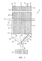
- FIG. 1 there is shown a system 10 for coating internal passages 12 of a workpiece 14, such as a blade or vane for use in a turbine engine.
- the workpiece 14 may have a root portion 16, a platform 18, and an airfoil portion 20.
- a plurality of internal passages 12 may extend from an opening 22 in the base 24 of the workpiece to an outlet cooling hole 26 at a tip end 28 of the airfoil portion 20. While the passages 12 have been shown as being linear passageways, it should be recognized that the passages 12 could be serpentine or otherwise non-linearly shaped. Often cross section dimensions, such as the diameters, of the passages 12 change across the width of the airfoil portion 20.
- the passage 12 adjacent the leading edge 30 of the airfoil portion 20 may have a relatively large cross section dimension, while the passage 12 adjacent the trailing edge 32 of the airfoil portion 20 may have a relatively small cross section dimension.
- the cooling hole 26 adjacent the leading edge 30 may have a cross section dimension which is greater than the cross section dimension of the cooling hole 26 adjacent the trailing edge 32.
- the system 10 includes a source 34 of an aluminide coating gas, such as AlF 3 gas.
- This gas may be generated in a remote location by a reaction of a halide activator (ie. AlF 3 , NH 4 F.HF, NH 3 Cl, AlCl 3 , etc.) with an aluminum-rich source metal (ie. CrAl, Co 2 Al 5 , NiAl, pure Al, etc.) at coating process temperature and fed to the inlet of the manifold by an Ar carrier gas.
- a typical aluminide coating process is from about 2 to 8 hours at a temperature in the range of 927-1149°C (1700 - 2100°F). Gas flows for internal coating range from 7.87 to 117.99 cm 3 /s (1.0 to 15.0 cfh) per part with higher pressures being used for longer or more complex passages.
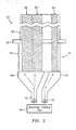
- the system 10 further includes a flow manifold 36 which has an inlet 38 for receiving the aluminide coating gas from the source 34.
- the inlet 38 may communicate with the source 34 using any suitable means known in the art.
- the manifold 36 may be attached to the base 24 of the workpiece 12 by any suitable means known in the art.
- the manifold 36 is attached to the base 24 in a way which prevents gas leakage between the manifold 36 and the base 24.
- the manifold 36 has an internal chamber 40 with a flow diverter 42 separating the chamber 40 into a first section 44 and a second section 46.
- the flow diverter 42 is set to cause a controlled portion of the incoming coating gas to flow into the opening 22 of the smaller cross section dimension passages(s).
- the actual percentage of flow which may be diverted is a function of the passage size and configuration.
- the flow diverter 42 has a first portion 48 which has a leading edge 50 within the inlet 38 of the manifold 36.
- the flow diverter 42 also has a second portion 52 which is angled with respect to the first portion 48.
- the second portion 52 extends to a point very close to or adjacent the outlet of the manifold 36.
- the flow diverter 42 prevents any flow of the coating gas between the sections 44 and 46.
- the flow diverter 42 may be stationary or movable so that the flow of the coating gas may be apportioned as needed.
- the portion 48 of the flow diverter may be laterally movable within the inlet 38 to apportion the gas flow as needed.
- the second portion 52 may be movable relative to the first portion 48 to change the relative size of the sections 44 and 46 and hence the amount of coating gas flow to the rearmost passage or passages 12.
- the provision of the flow diverter 42 allows a greater flow of coating gas to be directed to difficult to coat passages while still providing sufficient flow to the rest of the openings 22 to allow the formation of an acceptable coating on all internal surfaces 54.
- Tables I and II demonstrate the benefits of the manifold design of the present invention.
- a turbine blade with internal passages had the internal passages coated.
- the turbine blade which was used had a first passage adjacent the leading edge and a cooling hole with a diameter of 3.35 mm (0.132 inches), had second through eleventh passages and cooling holes with a diameter of 3.00 mm (0.118 inches), and a twelfth passageway, adjacent the trailing edge, and a cooling hole with a diameter of 1.75 mm (0.069 inches).
- Each outlet cooling hole was about 25.4 cm (10 inches) above the manifold.
- Table I are for a system where the manifold did not have a flow diverter in accordance with the present invention.
- the workpiece 14 such as a blade or vane for use in a turbine engine, may have a root portion 16, a platform 18, and an airfoil portion 20.
- the workpiece 14 may have one or more leading edge passages 60, one or more midbody passages 62, and one or more trailing edge passages 64.
- a source 66 of a coating gas such as an aluminide coating gas.
- the system 10' has a first flow manifold 68 and a second flow manifold 70.
- the first flow manifold 68 provides a first incoming coating gas flow to the inlets of the passages 60 and 62.
- the second flow manifold 70 provides a second incoming coating gas flow to the passage or passages 64.
- Suitable means, such as valves, may be provided for controlling the quantity of gas which flows through each of the manifolds 68 and 70. This approach allows each manifold 68 and 70 to flow at a different rate.
- each of the manifolds 68 and 70 may have its inlet 72 communicating with a separate coating gas source.
- one or more of the manifolds 68 and 70 may be provided with a flow diverter 42 as described hereinabove.
Landscapes
- Chemical & Material Sciences (AREA)
- General Chemical & Material Sciences (AREA)
- Chemical Kinetics & Catalysis (AREA)
- Engineering & Computer Science (AREA)
- Materials Engineering (AREA)
- Mechanical Engineering (AREA)
- Metallurgy (AREA)
- Organic Chemistry (AREA)
- Chemical Vapour Deposition (AREA)
- Turbine Rotor Nozzle Sealing (AREA)
- Polarising Elements (AREA)
- Feeding, Discharge, Calcimining, Fusing, And Gas-Generation Devices (AREA)
Claims (11)
- Verteiler (36) zur Verwendung in einem Prozess für die Beschichtung von unterschiedlich dimensionierten Passagen in einem Werkstück, aufweisend:eine interne Kammer (40);einen Einlass (38) zum Empfangen einer Strömung eines Beschichtungsgases; undeinen Strömungsteiler (42) innerhalb der internen Kammer (40) zum Trennen der Strömung des Beschichtungsgases in eine erste Strömung, die zum Beschichten einer vollen Länge von Oberflächen eines ersten Satzes von internen Passagen mit einer ersten Querschnittsabmessung ausreichend ist, und eine zweite Strömung, die zum Beschichten einer vollen Länge von Oberflächen eines zweiten Satzes von internen Passagen mit einer zweiten Querschnittsabmessung, die kleiner ist als die erste Querschnittsabmessung, ausreichend ist, wobei der Strömungsteiler (42) einen ersten Bereich (48) aufweist, der sich in den Einlass (38) hinein erstreckt, und einen zweiten Bereich (52) aufweist, der relativ zu dem ersten Bereich (48) in einem Winkel angeordnet ist, und wobei der Verteiler einen Auslass aufweist und sich der zweite Bereich (52) von dem ersten Bereich (48) zu einer Stelle in unmittelbarer Nähe von dem Auslass erstreckt.
- Verteiler nach Anspruch 1,
wobei der Strömungsteiler (42) im Inneren der Kammer stationär ist. - Verteiler nach Anspruch 1,
wobei der Strömungsteiler (42) im Inneren der Kammer beweglich ist. - System (10) zum Beschichten von internen Passagen (12) eines Werkstücks (14), aufweisend:eine Quelle (34) eines Beschichtungsgases; undeinen Verteiler (36) nach einem der vorausgehenden Ansprüche, der mit der Quelle (34) des Beschichtungsgases und mit dem Werkstück in Verbindung steht.
- System nach Anspruch 4,
wobei die Quelle (34) des Beschichtungsgases eine Aluminiumhalogenidgas-Quelle aufweist. - System nach Anspruch 4,
wobei die Quelle (34) des Beschichtungsgases eine AlF3-Quelle aufweist. - Verfahren zum Beschichten von internen Passagen (12) einer Turbinenmaschinenkomponente (14), wobei das Verfahren folgende Schritte aufweist:Bereitstellen einer Quelle (34) eines Beschichtungsgases;Bereitstellen eines Verteilers (36) nach einem der Ansprüche 1 bis 3, der mit der Quelle des Beschichtungsgases und mit dem Werkstück in Verbindung steht; undTrennen der Strömung des Beschichtungsgases innerhalb des Verteilers (36) in eine erste Strömung, die zum Beschichten einer vollen Länge von Oberflächen eines ersten Satzes von internen Passagen mit einer ersten Querschnittsabmessung ausreichend ist, und eine zweite Strömung, die zum Beschichten einer vollen Länge von Oberflächen eines zweiten Satzes von internen Passagen mit einer zweiten Querschnittsabmessung, die kleiner ist als die erste Querschnittsabmessung, ausreichend ist.
- Verfahren nach Anspruch 7,
das ferner das Zuführen der ersten Strömung zu einer Öffnung von jeder einer Mehrzahl von Passagen, die den ersten Satz von internen Passagen bilden, sowie das Zuführen der zweiten Strömung zu einer Öffnung von mindestens einer internen Passage, die den zweiten Satz von internen Passagen bilden, beinhaltet. - Verfahren nach Anspruch 8,
wobei der zweite Strömungs-Zuführschritt das Zuführen der zweiten Strömung zu einer Mehrzahl von internen Passagen beinhaltet, die den zweiten Satz von internen Passagen bilden. - Verfahren nach Anspruch 7, 8 oder 9,
wobei der Schritt der Bereitstellung einer Quelle (34) eines Beschichtungsgases das Bereitstellen einer Aluminiumhalogenidgas-Quelle beinhaltet. - Verfahren nach Anspruch 7, 8 oder 9,
wobei der Schritt des Bereitstellens einer Quelle eines Beschichtungsgases das Bereitstellen einer AlF3-Quelle beinhaltet.
Applications Claiming Priority (1)
| Application Number | Priority Date | Filing Date | Title |
|---|---|---|---|
| US11/089,989 US20060216415A1 (en) | 2005-03-24 | 2005-03-24 | Vapor aluminide coating gas manifold |
Publications (2)
| Publication Number | Publication Date |
|---|---|
| EP1705262A1 EP1705262A1 (de) | 2006-09-27 |
| EP1705262B1 true EP1705262B1 (de) | 2010-10-27 |
Family
ID=36522763
Family Applications (1)
| Application Number | Title | Priority Date | Filing Date |
|---|---|---|---|
| EP06251531A Not-in-force EP1705262B1 (de) | 2005-03-24 | 2006-03-22 | Gasverteiler mit einem Strömungsteiler |
Country Status (7)
| Country | Link |
|---|---|
| US (1) | US20060216415A1 (de) |
| EP (1) | EP1705262B1 (de) |
| JP (1) | JP4328776B2 (de) |
| CN (1) | CN1837403A (de) |
| AT (1) | ATE486152T1 (de) |
| DE (1) | DE602006017766D1 (de) |
| SG (1) | SG126093A1 (de) |
Families Citing this family (7)
| Publication number | Priority date | Publication date | Assignee | Title |
|---|---|---|---|---|
| US8020378B2 (en) * | 2004-12-29 | 2011-09-20 | Umicore Ag & Co. Kg | Exhaust manifold comprising aluminide |
| US7763326B2 (en) | 2006-12-20 | 2010-07-27 | United Technologies Corporation | Photocurable maskant composition and method of use |
| US20090134035A1 (en) * | 2007-08-02 | 2009-05-28 | United Technologies Corporation | Method for forming platinum aluminide diffusion coatings |
| US20090035485A1 (en) * | 2007-08-02 | 2009-02-05 | United Technologies Corporation | Method for forming active-element aluminide diffusion coatings |
| US20090136664A1 (en) * | 2007-08-02 | 2009-05-28 | United Technologies Corporation | Method for forming aluminide diffusion coatings |
| CN104334775B (zh) * | 2012-06-07 | 2017-05-10 | 索泰克公司 | 沉积系统的气体注入组件、包括这种组件的沉积系统和相关方法 |
| US11414759B2 (en) * | 2013-11-29 | 2022-08-16 | Taiwan Semiconductor Manufacturing Co., Ltd | Mechanisms for supplying process gas into wafer process apparatus |
Family Cites Families (10)
| Publication number | Priority date | Publication date | Assignee | Title |
|---|---|---|---|---|
| US4731004A (en) * | 1984-10-12 | 1988-03-15 | Princeton Packaging, Inc. | Side-by-side co-extrusion of film using multiple materials |
| EP0595159B1 (de) * | 1992-10-26 | 1997-12-29 | Schott Glaswerke | Verfahren und Vorrichtung zur Beschichtung der Innenfläche stark gewölbter im wesentlichen kalottenförmiger Substrate mittels CVD |
| US5911212A (en) * | 1996-05-20 | 1999-06-15 | Benson; Steven R. | Priority valve for an intercooled engine |
| US5800408A (en) * | 1996-11-08 | 1998-09-01 | Micro Therapeutics, Inc. | Infusion device for distributing infusate along an elongated infusion segment |
| US5928725A (en) * | 1997-07-18 | 1999-07-27 | Chromalloy Gas Turbine Corporation | Method and apparatus for gas phase coating complex internal surfaces of hollow articles |
| US6267664B1 (en) * | 2000-09-01 | 2001-07-31 | Alphonse J. Vandale | Exterior side view mirror and side window defogger system |
| US6905547B1 (en) * | 2000-12-21 | 2005-06-14 | Genus, Inc. | Method and apparatus for flexible atomic layer deposition |
| US6843882B2 (en) * | 2002-07-15 | 2005-01-18 | Applied Materials, Inc. | Gas flow control in a wafer processing system having multiple chambers for performing same process |
| US6929825B2 (en) * | 2003-02-04 | 2005-08-16 | General Electric Company | Method for aluminide coating of gas turbine engine blade |
| EP1866465A2 (de) * | 2005-01-18 | 2007-12-19 | ASM America, Inc. | Reaktionssystem zur herstellung eines dünnen films |
-
2005
- 2005-03-24 US US11/089,989 patent/US20060216415A1/en not_active Abandoned
-
2006
- 2006-03-20 SG SG200601825A patent/SG126093A1/en unknown
- 2006-03-22 AT AT06251531T patent/ATE486152T1/de not_active IP Right Cessation
- 2006-03-22 DE DE602006017766T patent/DE602006017766D1/de active Active
- 2006-03-22 EP EP06251531A patent/EP1705262B1/de not_active Not-in-force
- 2006-03-23 CN CNA2006100676715A patent/CN1837403A/zh active Pending
- 2006-03-24 JP JP2006082900A patent/JP4328776B2/ja not_active Expired - Fee Related
Also Published As
| Publication number | Publication date |
|---|---|
| JP2006265733A (ja) | 2006-10-05 |
| DE602006017766D1 (de) | 2010-12-09 |
| SG126093A1 (en) | 2006-10-30 |
| ATE486152T1 (de) | 2010-11-15 |
| US20060216415A1 (en) | 2006-09-28 |
| CN1837403A (zh) | 2006-09-27 |
| JP4328776B2 (ja) | 2009-09-09 |
| EP1705262A1 (de) | 2006-09-27 |
Similar Documents
| Publication | Publication Date | Title |
|---|---|---|
| CA2294261C (en) | Method and apparatus for gas phase coating complex internal surfaces of hollow articles | |
| US8741420B2 (en) | Component and methods of fabricating and coating a component | |
| EP1079073B1 (de) | Diffusionsbeschichtung aus modifiziertem Aluminid für die Innenfläche von Gasturbinenbauteilen | |
| US6929825B2 (en) | Method for aluminide coating of gas turbine engine blade | |
| EP1791989B1 (de) | Chrom- und aktivelementmodifizierte platin-aluminid-beschichtungen | |
| US6499949B2 (en) | Turbine airfoil trailing edge with micro cooling channels | |
| US8938879B2 (en) | Components with cooling channels and methods of manufacture | |
| US20130140007A1 (en) | Components with re-entrant shaped cooling channels and methods of manufacture | |
| US6905730B2 (en) | Aluminide coating of turbine engine component | |
| EP1927672B1 (de) | Diffusionsaluminidbeschichtungsvorgang | |
| US9249672B2 (en) | Components with cooling channels and methods of manufacture | |
| CN102953828A (zh) | 带有冷却通道的构件和制造方法 | |
| CN102839992A (zh) | 带有冷却通道的构件及制造方法 | |
| US20130056184A1 (en) | Components with re-entrant shaped cooling channels and methods of manufacture | |
| JP2012082518A (ja) | 冷却空気孔の管理が不要となる溶射方法 | |
| EP1445346B2 (de) | Beschichtung aus Aluminid für Gasturbinenschaufel | |
| EP1705262B1 (de) | Gasverteiler mit einem Strömungsteiler | |
| EP1895019B1 (de) | Verfahren und Vorrichtung zur Steuerung der Diffusionsbeschichtung interner Bereiche | |
| US20030072878A1 (en) | Method of protecting metal parts of turbomachines having holes and cavities by aluminizing the parts | |
| EP0769571B1 (de) | Verfahren zur Niedertemperaturbeschichtung eines Körpers mit Aluminium | |
| US20090017205A1 (en) | Apparatus and method for coating internal surfaces of a turbine engine component |
Legal Events
| Date | Code | Title | Description |
|---|---|---|---|
| PUAI | Public reference made under article 153(3) epc to a published international application that has entered the european phase |
Free format text: ORIGINAL CODE: 0009012 |
|
| AK | Designated contracting states |
Kind code of ref document: A1 Designated state(s): AT BE BG CH CY CZ DE DK EE ES FI FR GB GR HU IE IS IT LI LT LU LV MC NL PL PT RO SE SI SK TR |
|
| AX | Request for extension of the european patent |
Extension state: AL BA HR MK YU |
|
| 17P | Request for examination filed |
Effective date: 20070115 |
|
| 17Q | First examination report despatched |
Effective date: 20070219 |
|
| AKX | Designation fees paid |
Designated state(s): AT BE BG CH CY CZ DE DK EE ES FI FR GB GR HU IE IS IT LI LT LU LV MC NL PL PT RO SE SI SK TR |
|
| GRAP | Despatch of communication of intention to grant a patent |
Free format text: ORIGINAL CODE: EPIDOSNIGR1 |
|
| RTI1 | Title (correction) |
Free format text: GAS MANIFOLD WITH A FLOW DIVIDER |
|
| GRAS | Grant fee paid |
Free format text: ORIGINAL CODE: EPIDOSNIGR3 |
|
| GRAA | (expected) grant |
Free format text: ORIGINAL CODE: 0009210 |
|
| AK | Designated contracting states |
Kind code of ref document: B1 Designated state(s): AT BE BG CH CY CZ DE DK EE ES FI FR GB GR HU IE IS IT LI LT LU LV MC NL PL PT RO SE SI SK TR |
|
| REG | Reference to a national code |
Ref country code: GB Ref legal event code: FG4D |
|
| REG | Reference to a national code |
Ref country code: CH Ref legal event code: EP |
|
| REG | Reference to a national code |
Ref country code: IE Ref legal event code: FG4D |
|
| REF | Corresponds to: |
Ref document number: 602006017766 Country of ref document: DE Date of ref document: 20101209 Kind code of ref document: P |
|
| REG | Reference to a national code |
Ref country code: NL Ref legal event code: VDEP Effective date: 20101027 |
|
| LTIE | Lt: invalidation of european patent or patent extension |
Effective date: 20101027 |
|
| PG25 | Lapsed in a contracting state [announced via postgrant information from national office to epo] |
Ref country code: LT Free format text: LAPSE BECAUSE OF FAILURE TO SUBMIT A TRANSLATION OF THE DESCRIPTION OR TO PAY THE FEE WITHIN THE PRESCRIBED TIME-LIMIT Effective date: 20101027 |
|
| PG25 | Lapsed in a contracting state [announced via postgrant information from national office to epo] |
Ref country code: LV Free format text: LAPSE BECAUSE OF FAILURE TO SUBMIT A TRANSLATION OF THE DESCRIPTION OR TO PAY THE FEE WITHIN THE PRESCRIBED TIME-LIMIT Effective date: 20101027 Ref country code: SI Free format text: LAPSE BECAUSE OF FAILURE TO SUBMIT A TRANSLATION OF THE DESCRIPTION OR TO PAY THE FEE WITHIN THE PRESCRIBED TIME-LIMIT Effective date: 20101027 Ref country code: FI Free format text: LAPSE BECAUSE OF FAILURE TO SUBMIT A TRANSLATION OF THE DESCRIPTION OR TO PAY THE FEE WITHIN THE PRESCRIBED TIME-LIMIT Effective date: 20101027 Ref country code: NL Free format text: LAPSE BECAUSE OF FAILURE TO SUBMIT A TRANSLATION OF THE DESCRIPTION OR TO PAY THE FEE WITHIN THE PRESCRIBED TIME-LIMIT Effective date: 20101027 Ref country code: PT Free format text: LAPSE BECAUSE OF FAILURE TO SUBMIT A TRANSLATION OF THE DESCRIPTION OR TO PAY THE FEE WITHIN THE PRESCRIBED TIME-LIMIT Effective date: 20110228 Ref country code: BG Free format text: LAPSE BECAUSE OF FAILURE TO SUBMIT A TRANSLATION OF THE DESCRIPTION OR TO PAY THE FEE WITHIN THE PRESCRIBED TIME-LIMIT Effective date: 20110127 Ref country code: IS Free format text: LAPSE BECAUSE OF FAILURE TO SUBMIT A TRANSLATION OF THE DESCRIPTION OR TO PAY THE FEE WITHIN THE PRESCRIBED TIME-LIMIT Effective date: 20110227 Ref country code: AT Free format text: LAPSE BECAUSE OF FAILURE TO SUBMIT A TRANSLATION OF THE DESCRIPTION OR TO PAY THE FEE WITHIN THE PRESCRIBED TIME-LIMIT Effective date: 20101027 Ref country code: SE Free format text: LAPSE BECAUSE OF FAILURE TO SUBMIT A TRANSLATION OF THE DESCRIPTION OR TO PAY THE FEE WITHIN THE PRESCRIBED TIME-LIMIT Effective date: 20101027 |
|
| PG25 | Lapsed in a contracting state [announced via postgrant information from national office to epo] |
Ref country code: GR Free format text: LAPSE BECAUSE OF FAILURE TO SUBMIT A TRANSLATION OF THE DESCRIPTION OR TO PAY THE FEE WITHIN THE PRESCRIBED TIME-LIMIT Effective date: 20110128 Ref country code: BE Free format text: LAPSE BECAUSE OF FAILURE TO SUBMIT A TRANSLATION OF THE DESCRIPTION OR TO PAY THE FEE WITHIN THE PRESCRIBED TIME-LIMIT Effective date: 20101027 |
|
| PG25 | Lapsed in a contracting state [announced via postgrant information from national office to epo] |
Ref country code: EE Free format text: LAPSE BECAUSE OF FAILURE TO SUBMIT A TRANSLATION OF THE DESCRIPTION OR TO PAY THE FEE WITHIN THE PRESCRIBED TIME-LIMIT Effective date: 20101027 Ref country code: ES Free format text: LAPSE BECAUSE OF FAILURE TO SUBMIT A TRANSLATION OF THE DESCRIPTION OR TO PAY THE FEE WITHIN THE PRESCRIBED TIME-LIMIT Effective date: 20110207 Ref country code: CZ Free format text: LAPSE BECAUSE OF FAILURE TO SUBMIT A TRANSLATION OF THE DESCRIPTION OR TO PAY THE FEE WITHIN THE PRESCRIBED TIME-LIMIT Effective date: 20101027 |
|
| PG25 | Lapsed in a contracting state [announced via postgrant information from national office to epo] |
Ref country code: SK Free format text: LAPSE BECAUSE OF FAILURE TO SUBMIT A TRANSLATION OF THE DESCRIPTION OR TO PAY THE FEE WITHIN THE PRESCRIBED TIME-LIMIT Effective date: 20101027 Ref country code: RO Free format text: LAPSE BECAUSE OF FAILURE TO SUBMIT A TRANSLATION OF THE DESCRIPTION OR TO PAY THE FEE WITHIN THE PRESCRIBED TIME-LIMIT Effective date: 20101027 Ref country code: PL Free format text: LAPSE BECAUSE OF FAILURE TO SUBMIT A TRANSLATION OF THE DESCRIPTION OR TO PAY THE FEE WITHIN THE PRESCRIBED TIME-LIMIT Effective date: 20101027 Ref country code: DK Free format text: LAPSE BECAUSE OF FAILURE TO SUBMIT A TRANSLATION OF THE DESCRIPTION OR TO PAY THE FEE WITHIN THE PRESCRIBED TIME-LIMIT Effective date: 20101027 |
|
| PLBE | No opposition filed within time limit |
Free format text: ORIGINAL CODE: 0009261 |
|
| STAA | Information on the status of an ep patent application or granted ep patent |
Free format text: STATUS: NO OPPOSITION FILED WITHIN TIME LIMIT |
|
| 26N | No opposition filed |
Effective date: 20110728 |
|
| PG25 | Lapsed in a contracting state [announced via postgrant information from national office to epo] |
Ref country code: MC Free format text: LAPSE BECAUSE OF NON-PAYMENT OF DUE FEES Effective date: 20110331 |
|
| REG | Reference to a national code |
Ref country code: CH Ref legal event code: PL |
|
| REG | Reference to a national code |
Ref country code: DE Ref legal event code: R097 Ref document number: 602006017766 Country of ref document: DE Effective date: 20110728 |
|
| REG | Reference to a national code |
Ref country code: FR Ref legal event code: ST Effective date: 20111130 |
|
| PG25 | Lapsed in a contracting state [announced via postgrant information from national office to epo] |
Ref country code: IT Free format text: LAPSE BECAUSE OF FAILURE TO SUBMIT A TRANSLATION OF THE DESCRIPTION OR TO PAY THE FEE WITHIN THE PRESCRIBED TIME-LIMIT Effective date: 20101027 |
|
| REG | Reference to a national code |
Ref country code: IE Ref legal event code: MM4A |
|
| PG25 | Lapsed in a contracting state [announced via postgrant information from national office to epo] |
Ref country code: LI Free format text: LAPSE BECAUSE OF NON-PAYMENT OF DUE FEES Effective date: 20110331 Ref country code: CH Free format text: LAPSE BECAUSE OF NON-PAYMENT OF DUE FEES Effective date: 20110331 Ref country code: IE Free format text: LAPSE BECAUSE OF NON-PAYMENT OF DUE FEES Effective date: 20110322 Ref country code: FR Free format text: LAPSE BECAUSE OF NON-PAYMENT OF DUE FEES Effective date: 20110331 |
|
| PGFP | Annual fee paid to national office [announced via postgrant information from national office to epo] |
Ref country code: DE Payment date: 20130320 Year of fee payment: 8 Ref country code: GB Payment date: 20130320 Year of fee payment: 8 |
|
| PG25 | Lapsed in a contracting state [announced via postgrant information from national office to epo] |
Ref country code: LU Free format text: LAPSE BECAUSE OF NON-PAYMENT OF DUE FEES Effective date: 20110322 Ref country code: CY Free format text: LAPSE BECAUSE OF FAILURE TO SUBMIT A TRANSLATION OF THE DESCRIPTION OR TO PAY THE FEE WITHIN THE PRESCRIBED TIME-LIMIT Effective date: 20101027 |
|
| PG25 | Lapsed in a contracting state [announced via postgrant information from national office to epo] |
Ref country code: TR Free format text: LAPSE BECAUSE OF FAILURE TO SUBMIT A TRANSLATION OF THE DESCRIPTION OR TO PAY THE FEE WITHIN THE PRESCRIBED TIME-LIMIT Effective date: 20101027 |
|
| PG25 | Lapsed in a contracting state [announced via postgrant information from national office to epo] |
Ref country code: HU Free format text: LAPSE BECAUSE OF FAILURE TO SUBMIT A TRANSLATION OF THE DESCRIPTION OR TO PAY THE FEE WITHIN THE PRESCRIBED TIME-LIMIT Effective date: 20101027 |
|
| REG | Reference to a national code |
Ref country code: DE Ref legal event code: R119 Ref document number: 602006017766 Country of ref document: DE |
|
| GBPC | Gb: european patent ceased through non-payment of renewal fee |
Effective date: 20140322 |
|
| REG | Reference to a national code |
Ref country code: DE Ref legal event code: R119 Ref document number: 602006017766 Country of ref document: DE Effective date: 20141001 |
|
| PG25 | Lapsed in a contracting state [announced via postgrant information from national office to epo] |
Ref country code: GB Free format text: LAPSE BECAUSE OF NON-PAYMENT OF DUE FEES Effective date: 20140322 Ref country code: DE Free format text: LAPSE BECAUSE OF NON-PAYMENT OF DUE FEES Effective date: 20141001 |