EP1705103B1 - Vehicle panel - Google Patents
Vehicle panel Download PDFInfo
- Publication number
- EP1705103B1 EP1705103B1 EP20060003931 EP06003931A EP1705103B1 EP 1705103 B1 EP1705103 B1 EP 1705103B1 EP 20060003931 EP20060003931 EP 20060003931 EP 06003931 A EP06003931 A EP 06003931A EP 1705103 B1 EP1705103 B1 EP 1705103B1
- Authority
- EP
- European Patent Office
- Prior art keywords
- panel
- linear reinforcement
- vehicle
- linear
- wires
- Prior art date
- Legal status (The legal status is an assumption and is not a legal conclusion. Google has not performed a legal analysis and makes no representation as to the accuracy of the status listed.)
- Expired - Fee Related
Links
Images


Classifications
-
- B—PERFORMING OPERATIONS; TRANSPORTING
- B60—VEHICLES IN GENERAL
- B60J—WINDOWS, WINDSCREENS, NON-FIXED ROOFS, DOORS, OR SIMILAR DEVICES FOR VEHICLES; REMOVABLE EXTERNAL PROTECTIVE COVERINGS SPECIALLY ADAPTED FOR VEHICLES
- B60J7/00—Non-fixed roofs; Roofs with movable panels, e.g. rotary sunroofs
- B60J7/08—Non-fixed roofs; Roofs with movable panels, e.g. rotary sunroofs of non-sliding type, i.e. movable or removable roofs or panels, e.g. let-down tops or roofs capable of being easily detached or of assuming a collapsed or inoperative position
- B60J7/10—Non-fixed roofs; Roofs with movable panels, e.g. rotary sunroofs of non-sliding type, i.e. movable or removable roofs or panels, e.g. let-down tops or roofs capable of being easily detached or of assuming a collapsed or inoperative position readily detachable, e.g. tarpaulins with frames, or fastenings for tarpaulins
- B60J7/106—Non-fixed roofs; Roofs with movable panels, e.g. rotary sunroofs of non-sliding type, i.e. movable or removable roofs or panels, e.g. let-down tops or roofs capable of being easily detached or of assuming a collapsed or inoperative position readily detachable, e.g. tarpaulins with frames, or fastenings for tarpaulins readily detachable hard-tops
-
- B—PERFORMING OPERATIONS; TRANSPORTING
- B62—LAND VEHICLES FOR TRAVELLING OTHERWISE THAN ON RAILS
- B62D—MOTOR VEHICLES; TRAILERS
- B62D25/00—Superstructure or monocoque structure sub-units; Parts or details thereof not otherwise provided for
-
- B—PERFORMING OPERATIONS; TRANSPORTING
- B62—LAND VEHICLES FOR TRAVELLING OTHERWISE THAN ON RAILS
- B62D—MOTOR VEHICLES; TRAILERS
- B62D29/00—Superstructures, understructures, or sub-units thereof, characterised by the material thereof
- B62D29/04—Superstructures, understructures, or sub-units thereof, characterised by the material thereof predominantly of synthetic material
- B62D29/043—Superstructures
Definitions
- the present invention relates to a vehicle panel as a component of a vehicle body such as a hard roof, a lift gate or a rear gate.
- the present invention relates to a panel including a panel body prepared by bonding an outer panel and an inner panel and a linear reinforcement arranged between the outer and inner panels.
- Japanese Unexamined Patent Publication No. 10-297286 discloses a hard roof for convertibles which is detachable from a vehicle body.
- the vehicle panel is a back door structure disclosed by Japanese Examined Utility Model Publication No. 05-34970 Y2 .
- the back door includes an outer panel and an inner panel which are bonded together and a wire provided between the outer and inner panels.
- the wire prevents the back door from falling off the vehicle body.
- One end of the wire is fixed to a hinge connecting the back door and the vehicle body and the other end is fixed to the inner panel, while the other part of the wire between the fixed ends is kept loosened.
- the hard roof or the back door described above is made of resin. Therefore, when a load is applied in a collision to a vehicle provided with the hard roof or the back door, the hard roof or the back door is disassembled by the large load.
- the wire arranged in the panel is kept loosened. Therefore, the wire may hit the inner panel and/or the outer panel while the car is driven, thereby making noise.
- An object of the present invention is to prevent a vehicle panel from being disassembled and scattered even when the vehicle panel is broken under a large load applied in a collision.
- the present invention is directed to a vehicle panel including: a panel prepared by bonding an outer panel and an inner panel; and a linear reinforcement in the form of a wire arranged between the outer panel and the inner panel.
- the outer panel or the inner panel includes two or more fixing parts for fixing the linear reinforcement and at least one projection provided between the fixing parts.
- the linear reinforcement is supported by the projection between the fixing parts to be spaced from the outer and inner panels while tension is applied to the linear reinforcement.
- the linear reinforcement is a wire.
- the panel By arranging the linear reinforcement within the panel, the panel is prevented from being disassembled and scattered even when the panel is broken by a large load applied in a collision. Since the linear reinforcement is stretched and spaced from the panels, the linear reinforcement does not hit the inner panel and/or the outer panel even if the linear reinforcement vibrates when the car is running.
- the panel may include two or more mounting parts and may be detachably attached to a vehicle body with the mounting parts.
- the linear reinforcement may connect the mounting parts together.
- the linear reinforcement may connect the mounting parts which are arranged at both ends of the panel in the vehicle width direction.
- the linear reinforcement may connect the mounting parts which are arranged to be spaced from each other in the longitudinal direction of the vehicle body.
- the linear reinforcement may connect the mounting parts which are arranged at different heights.
- the linear reinforcement may connect the mounting parts via plate-like reinforcements.
- the mounting parts are attached to the panel with improved firmness. Further, the linear reinforcement and the mounting parts are connected more easily in the manufacture of the panel.
- the linear reinforcement may be arranged along almost the entire circumference of the panel.
- a load applied to the vehicle body in any of frontal, side, rear and offset collisions is dispersed effectively. Further, the panel is prevented from being scattered.
- the linear reinforcement may include an upper linear reinforcement and a lower linear reinforcement. With use of the twin linear reinforcement, the panel improves in resistance against the impact load.
- the linear reinforcement may substantially be in the form of a closed loop and arranged along at least part of the circumference of the panel.
- the panel is prevented from being disassembled and scattered even if an impact load is applied to the panel from any direction.
- the linear reinforcement may be divided into two or more line segments and both ends of each of the line segments may be fixed by the fixing parts.
- the number of the fixing parts increases and the load applied to the panel is dispersed more easily.
- the panel improves in resistance against the impact load.
- the line segments may include upper line segments and lower line segments.
- the panel further improves in resistance against the impact load.
- the line segments may be connected together via the plate-like reinforcements attached to the outer panel or the inner panel.
- the line segments are securely connected together via the plate-like reinforcements, the line segments are attached with improved firmness. This brings about an improvement in load transfer among the line segments.
- the projection may be provided with a recess for supporting the linear reinforcement.
- the linear reinforcement is supported by the recess, the linear reinforcement is surely prevented from coming off the projection even when it vibrates while the car is running.
- the panel is manufactured by arranging the linear reinforcement and then bonding the inner panel and the outer panel undetachably, it is extremely important that the linear reinforcement does not come off the projection.
- the direction of extension of the linear reinforcement may be changed by the recess.
- the linear reinforcement is hooked on the recess more favorably. Even if the panel is curved three-dimensionally, the linear reinforcement is arranged along the curve. Thus, the degree of freedom in arranging the linear reinforcement improves.
- the linear reinforcement includes an upper linear reinforcement and a lower linear reinforcement
- the projection is provided with two recesses corresponding to the upper and lower linear reinforcements and the upper and lower reinforcements are arranged such that parts thereof between the projection and the fixing part are not parallel to each other.
- the resistance of the panel improves. Further, as the two linear reinforcements are arranged such that parts thereof between the projection and the fixing part are not parallel to each other, the direction of extension of the linear reinforcements is changed three-dimensionally corresponding to the shape of the panel. Moreover, the linear reinforcements are suitably engaged with the recesses, thereby preventing the linear reinforcements from coming off with higher reliability.
- the projection may be arranged near an opening formed in the outer panel or the inner panel. Accordingly, the opening is reinforced with the projection for supporting the linear reinforcement.
- the opening may be the one for attaching a trim for covering the cabin side of the inner panel.
- the panel may be a roof detachable from the vehicle body.
- the roof of a vehicle is likely to receive a load in a frontal, side, rear or offset collision, the roof provided with the linear reinforcement is prevented from being disassembled or scattered in the collision. That is, the panel of the present invention is suitable for a hard roof (detachable hardtop).
- FIG. 1 illustrates a convertible 6 to which the panel of the present invention is applied.
- the convertible 6 includes a front windshield 3 surrounded by left and right front pillars 1 and a front header 2, up-and-down side windows 4 and a rear deck 5. Further, a hard roof 7 (detachable hardtop) storing therein an open/close hood (not shown) is attached to the convertible 6.
- the hard roof 7 includes an outer panel 8 which forms part of the outer surface of the vehicle and an inner panel 9 integrally bonded to the cabin side of the outer panel 8.
- the panels 8 and 9 are made of resin such as a seat molding compound (SMC).
- the inner panel 9 includes a front side part 9A extending in the vehicle width direction, a rear side part 9B extending in the vehicle direction at a position more rearward than the front side part 9A, a bottom side part 9C extending in the vehicle width direction at a position more rearward than the rear side part 9B, flank side parts 9D extending in the longitudinal direction of the vehicle body to connect the ends of the side part 9A and the ends of the side parts 9B and vertical side parts 9E extending in the vertical direction to connect the ends of the side parts 9B and 9D with the front ends of the side 9C.
- the inner panel 9 includes the integral side parts 9A to 9E.
- the inner panel 9 further includes an opening 10 defined by the front side part 9A, rear side part 9B and left and right flank side parts 9D and an opening 11 defined by the rear side part 9B, bottom side part 9C and the left and right vertical side parts 9E.
- the opening 10 is provided for weight reduction.
- a rear windshield 12 is attached to the rim of the opening 11 (see FIG. 3 ).
- the hard roof 7 is detachably attached to the vehicle body with use of a top lock 13, wedges 14, side locks 15, and rear deck locks 16.
- the top lock 13 is attached to the middle of the front side part 9A in the vehicle width direction.
- the top lock 13 includes a hook 18, a cover 19 and a base 20.
- the hook 18 is detachably engaged with an engagement pin (not shown) attached to the front header 2 by the operation of a lever 17.
- Details of the top lock 13 are disclosed by Japanese Examined Utility Model Publication No. 07-28023 .
- the base 20 is attached to the front side part 9A with bolts 21 and nuts 22.
- a steel reinforcement 23 is bonded in advance to the middle of the upper surface of the front side part 9A.
- the base 20, front side part 9A and reinforcement 23 are fastened together with the above-described bolts 21 and nuts 22.
- a trim 24 top ceiling covers the opening 10 from the cabin side and a trim 25 (rear trim) covers the bottom side part 9C of the inner panel 9 from the cabin side.
- the wedges 14 are attached to both ends of the front side part 9A from the bottom surface, respectively.
- Each of the wedges 14 includes two positioning pins 26 and 27 and a wedged tip 29 covered with a rubber piece 28.
- Each of the wedges 14 properly positioned by the positioning pins 26 and 27 is attached to the front side part 9A with bolts 30 and nuts 31.
- Steel reinforcements 32 are bonded in advance to both ends of the front side part 9A from the top surface, respectively.
- Each of the wedges 14 is fastened together with the front side part 9A and the reinforcement 32 with the bolts 30 and the nuts 31.
- the reinforcements 32 are arranged at the corners formed by the front side part 9A and the flank side parts 9D to contact both of the side parts 9A and 9D.
- the front header 2 includes a header outer panel 33 and a header inner panel 34 which are bonded together to provide therebetween closed header space 35 extending in the vehicle width direction.
- a sealing member 36 is attached to a bonding flange of the front header 2.
- Supports 39 are fixed to the header inner panel 34 with bolts 37 and nuts 38 to receive the wedges 14, respectively.
- Each of the supports 39 has a recess 39a for receiving the wedged tip 29 of the wedge 14, thereby positioning the hard roof 7 at two side parts with respect to the vehicle body.
- the side locks 15 are attached to the vertical side parts 9E, respectively, as shown in FIGS. 2 and 6 .
- Each of the side locks 15 includes a hook 42, a tapered positioning pin 43 and a base 44.
- the hook 42 is locked/unlocked by a handle 41 which rotates around a pivot 40.
- the base 44 is attached to the vertical side part 9E with two or more bolts 45 and two or more nuts 46 (in FIG. 6 , only a single bolt and nut pair is shown).
- Steel reinforcements 47 are bonded in advance to the outer surface of the vertical side parts 9E, respectively.
- the base 44, vertical side part 9E and the reinforcement 47 are fastened together with the bolts 45 and the nuts 46.
- Each of the reinforcements 47 extends upward as shown in FIG. 9 such that the top thereof approaches the corner formed by the side parts 9D, 9B and 9E.
- a trim 48 covers the vertical side part 9E of the inner panel 9 from the cabin side.
- the trim 48 may be integral with the trim 24 shown in FIG. 3 .
- Reference numeral 49 indicates a weatherstrip.
- strikers 50 corresponding to the side locks 15 are fixed.
- Each of the strikers 50 includes a hook hole 51 and a tapered hole 52 as shown in FIG. 7 .
- the tapered pin 43 of the side lock 15 is inserted into the tapered hole 52 and the hook 42 is engaged with the hook hole 51, the bottom side parts of the hard roof 7 are engaged with the center pillar of the vehicle body.
- the rear deck locks 16 are attached to the bottom side part 9C to be spaced from each other in the vehicle width direction.
- Each of the rear deck locks 16 includes a base plate 54 having an opening 53, a lock plate 56 fixed to the rear part of the base plate 54 from above with a spacer 55 sandwiched therebetween and a cover 57.
- a front portion of the base plate 54 is inserted into the bottom side part 9C of the inner panel 9.
- the rear deck 5 has engagement pins 58 (lock pins) each having a head 58a.
- the engagement pins 58 are inserted into the openings 53 of the rear deck locks 16 and the rear deck locks 16 are shifted forward with the engagement pins 58 and the heads 58a kept protruding upward from the openings 53. By so doing, the engagement pins 58 are engaged with the lock plates 56.
- the left and right sides of the rear part of the hard roof 7 are engaged with the vehicle body.
- a sealing member 59 is provided around the circumference of the rear windshield 12 and a weatherstrip 60 is attached to a projection extending from a bottom side part 9C of the inner panel 9.
- FIGS. 9 to 13 illustrate the arrangement of the linear reinforcement W.
- the linear reinforcement W is arranged along at least part of the circumference of the inner panel 9, i.e., along the front side part 9A, flank side parts 9D and rear side part 9B to be substantially in the form of a closed loop.
- FIG. 13 is a plan view illustrating the extraction of the linear reinforcement W.
- the linear reinforcement W includes discontinuous 10 line segments (wires W1to W6).
- the wires W1, W3 and W5 are arranged more upward than the wires W2, W4 and W6.
- the arrangement of the wires W1 to W6 is left-right symmetric when viewed in plan.
- Each of the wires W1 to W6 has wire brackets 61 at both ends thereof.
- Each of the wire brackets 61 is formed by casting with the wire end placed in a casting mold.
- the wire brackets 61 have mounting holes 62, respectively.
- the wire brackets 61 of the wires W1 to W6 are fixed to the reinforcements 23, 32 and 47 with bolt and nut pairs 63.
- the wires W1 and W2 are arranged along the front side part 9A of the inner panel 9 between the reinforcements 23 and 32 while ones of the ends thereof are fixed to the reinforcements 23 and the others are fixed to the reinforcements 32.
- the wires W2 located below the wires W1 extend linearly along the front side part 9A of the inner panel 9 between the reinforcements 23 and 32.
- the middle portions of the wires W1 located above the wires W2 are hooked on recesses 64a of ribs 64 (see FIG. 15 ) which are integral with the inner panel 9 and positioned close to the reinforcements 23 and 32. As a result, interference between the upper wires W1 and the lower wires W2 is prevented.
- the upper and lower wires W1 and W2 are placed in space 65 formed between the outer and inner panels 8 and 9 (see FIGS. 4 and 5 ). In order to prevent unusual sounds from occurring, other parts of the wires W1 and W2 than the fixed ends are free from contact with the panels 8 and 9 with a possible tension applied thereto.
- the wires W3 and W4 are arranged along the flank side parts 9A of the inner panel 9 between the reinforcements 32 and 47 while ones of the ends thereof are fixed to the reinforcements 32 and the others are fixed to the reinforcements 47.
- each of the flank side parts 9D two ribs 66 are integrally protrude from the inner panel 9 between the reinforcements 32 and 47.
- Each of the ribs 66 has an upper recess 67 and a lower recess 68 as shown in FIG. 16 .
- wires W3 above the wires W4 are supported by the upper recesses 67 of the ribs 66, while the wires W4 below the wires W3 are supported by the lower recesses 68 of the ribs 66.
- the wires W3 and W4 are hooked on the recesses 67 and 68 of the ribs 66.
- the wires W3 and W4 are supported with a possible tension applied thereto. Therefore, other parts of the wires W3 and W4 than the fixed ends are free from contact with the panels 8 and 9.
- the upper and lower recesses 67 and 68 change the direction of extension of the wires W3 and W4 three-dimensionally along the shape of the hard roof 7.
- Parts of the upper and lower wires W3 and W4 between the front rib 66 and the reinforcement 32 are arranged nonparallel to each other, and so are parts of the wires W3 and W4 between the rear rib 66 and the reinforcement 47.
- the ribs 66 are formed near trim mounting holes 70 formed in the inner panel 9 as shown in FIGS. 11 and 12 .
- the trim 24 protrude from the cabin side of the inner panel 9 to the outside through the trim mounting holes 70.
- the trim 24 is fixed to the inner panel 9 by fitting fasteners 71 on the bosses. As shown in FIGS. 11 and 12 , the fasteners 71 are positioned between the upper and lower wires W3 and W4 and do not contact with any of the wires W3 and W4.
- the wires W5 and W6 are arranged along the rear side part 9B between the left and right reinforcements 47 while ones of the ends thereof are fixed to the left reinforcements 47 and the others are fixed to the right reinforcements 47.
- Two or more integral ribs 72 are formed at the top of the vertical side parts 9E and two or more integral ribs 73 are formed at the rear side part 9B.
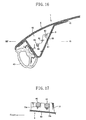
- Each of the ribs 72 and 73 is provided with two recesses 73a and 73b for supporting the wires W5 and W6 separately (see FIG. 17 ).
- the wires W5 above the wires W6 are supported by the recesses 73a, while the wires W6 below the wires W5 are supported by the recesses 73b.
- the wires W5 and W6 are supported by the ribs 72 and 73 in the space formed between the panels 8 and 9 with a possible tension applied thereto such that other parts of the wires W5 and W6 than the fixed ends do not contact any of the panels 8 and 9.
- the hard roof 7 is prevented from being disassembled or scattered in pieces because the wires W1 to W6 are arranged within the hard roof 7. Further, since the wires W1 to W6 are spaced from the panels 8 and 9 by the ribs 64, 66, 72 and 73, the occurrence of unusual sounds caused between the inner or outer panels 8 or 9 and the wires W1 to W6 is prevented in a normal driving mode.
- the mounting parts (top lock 13, wedges 14, side locks 15 and rear deck locks 16) are connected via the wires W1 to W6. Therefore, when a large load is applied to the hard roof 7 in a collision, the load transferred from the vehicle body to the mounting parts is dispersed among the mounting parts. Even if a portion of the hard roof 7 close to any of the mounting parts is broken, the scattering of the hard roof 7 is prevented because the mounting part is connected to the other mounting parts via the wires W1 to W6.
- the wedges 14 arranged at the widthwise ends of the hard roof 7 are connected to each other in the vehicle width direction through the wires W1 and W2 and the reinforcements 23 and 32. Further, the side locks 15 arranged at the widthwise ends of the hard roof 7 are connected to each other in the vehicle width direction through the wires W5 and W6 and the reinforcements 47. Therefore, when a large load is applied to any one of the wedges 14 or any one of the side locks 15 in a side or offset collision, the load is dispersed effectively.
- the wedges 14 and the side locks 15 arranged to be spaced from each other in the longitudinal direction of the vehicle body are connected through the wires W3 and W4 and the reinforcements 32 and 47. Therefore, when a large load is applied to the wedges 14 or the side locks 15 in a frontal or rear collision, the load is dispersed effectively.
- the wedges 14 and the side locks 15 attached to the hard roof 7 at different heights are connected to each other through the wires W3 and W4 and the reinforcements 32 and 47. Therefore, when a large load is applied to the wedges 14 or the side locks 15 in a collision, the load is dispersed effectively.
- the ends of the wires W1 to W6 are connected to the top lock 13, wedges 14 and side locks 15 through the reinforcements 23, 32 and 47. Therefore, a load applied to the wires W1 to W6 are transferred to the vehicle body via the reinforcements 23, 32 and 47 and the mounting parts.
- the mounting parts are attached to the hard roof 7 with improved firmness.
- wires W1 to W6 and the mounting parts are connected easily in the manufacture of the hard roof 7.
- the linear reinforcement W is arranged along the side parts 9A, 9B and 9D to be substantially in the form of a closed loop.
- the closed loop is formed of the wires W1 to W6. Both ends of each of the wires W1 to W6 are fixed with bolt and nut pairs 63, respectively. As the number of the bolt and nut pairs 63 fixing the linear reinforcement increases, the applied load is easily dispersed. Therefore, the hard roof 7 improves in resistance against the impact load.
- the linear reinforcement W has a twinned structure including the upper wires W1 , W3, and W5 and the lower wires W2, W4 and W6, the hard roof further improves in resistance against the impact load.
- the wires W1 to W6 are connected together via the reinforcements 23, 32 and 47, the wires W1 to W6 improves in load transfer among the wires W1 to W6.
- the wires W1 to W6 are supported by the recesses 64a, 67, 68, 73a and 73b formed in the ribs 64, 66, 72 and 73. Therefore, the wires W1 to W6 are surely prevented from coming off the ribs 64, 66, 72 and 73 due to vibrations of the running vehicle.
- the hard roof 7 is formed by arranging the wires W1 to W6 and then bonding the outer and inner panels 8 and 9 in an undetachable manner. Therefore, it is excellently effective that the wires W1 to W6 do not come off the ribs.
- the bolt and nut pairs 63 fixing the front ends of the wires W3 and W4 and those fixing the rear ends are positioned lower than the recesses 67 and 68 of the ribs 66. Specifically, parts of the wires W3 and W4 between the ribs 66 and the fixed ends are skewed to each other (the two wires W3 and W4 are not parallel and do not intersect each other).
- the direction of extension of the wires W3 and W4 are three-dimensionally changed by the recesses 67 and 68, thereby engaging the wires W3 and W4 suitably with the recesses 67 and 68.
- the wires W3 and W4 are surely prevented from coming off the ribs 66.
- the ribs 66 are arranged near the trim mounting holes 70 formed in the inner panel 9. Therefore, the ribs 66 also serve as reinforcement for the trim mounting holes 70. As a result, the rigidity of the hard roof 7 improves and the trim is attached with high firmness.
- FIG. 18 illustrates another embodiment of the rib.
- Two recesses 67 and 68 of the rib are tapered downward. With this structure, the recesses 67 and 68 improve in holding the wires W3 and W4. The thus configured ribs achieve the same effect as those of the above-described embodiment.
- the arrangement of the linear reinforcement W is not particularly limited to the one described above and may be changed as required.
- the present invention is not limited to the hard roof 7.
- the present invention may be applied to a vehicle panel as a component of the vehicle body such as a lift gate or a rear gate.
Description
- The present invention relates to a vehicle panel as a component of a vehicle body such as a hard roof, a lift gate or a rear gate. In particular, the present invention relates to a panel including a panel body prepared by bonding an outer panel and an inner panel and a linear reinforcement arranged between the outer and inner panels.
- As an example of a vehicle panel,
Japanese Unexamined Patent Publication No. 10-297286 - Another example of the vehicle panel is a back door structure disclosed by
Japanese Examined Utility Model Publication No. 05-34970 Y2 - The hard roof or the back door described above is made of resin. Therefore, when a load is applied in a collision to a vehicle provided with the hard roof or the back door, the hard roof or the back door is disassembled by the large load.
- Further, as to the panel disclosed by the latter publication, the wire arranged in the panel is kept loosened. Therefore, the wire may hit the inner panel and/or the outer panel while the car is driven, thereby making noise.
-
DE 100 56 796 A1 discloses a vehicle panel according to the preamble part of claim 1. - An object of the present invention is to prevent a vehicle panel from being disassembled and scattered even when the vehicle panel is broken under a large load applied in a collision.
- The present invention is directed to a vehicle panel including: a panel prepared by bonding an outer panel and an inner panel; and a linear reinforcement in the form of a wire arranged between the outer panel and the inner panel.
- The outer panel or the inner panel includes two or more fixing parts for fixing the linear reinforcement and at least one projection provided between the fixing parts. The linear reinforcement is supported by the projection between the fixing parts to be spaced from the outer and inner panels while tension is applied to the linear reinforcement.
- The linear reinforcement is a wire.
- By arranging the linear reinforcement within the panel, the panel is prevented from being disassembled and scattered even when the panel is broken by a large load applied in a collision. Since the linear reinforcement is stretched and spaced from the panels, the linear reinforcement does not hit the inner panel and/or the outer panel even if the linear reinforcement vibrates when the car is running.
- The panel may include two or more mounting parts and may be detachably attached to a vehicle body with the mounting parts. The linear reinforcement may connect the mounting parts together.
- By connecting the mounting parts with the linear reinforcement, a load transferred from the vehicle body to one of the mounting parts is dispersed to the other mounting parts. Further, if a portion of the panel close to one of the mounting parts is broken, the panel is prevented from being scattered because the mounting part is connected to the other mounting parts by the linear reinforcement.
- The linear reinforcement may connect the mounting parts which are arranged at both ends of the panel in the vehicle width direction. By so doing, when a load is applied to any of the left and right mounting parts in a side or offset collision, the load is dispersed effectively.
- The linear reinforcement may connect the mounting parts which are arranged to be spaced from each other in the longitudinal direction of the vehicle body. By so doing, when a load is applied to any of the front and rear mounting parts in a frontal or rear collision, the load is dispersed effectively.
- The linear reinforcement may connect the mounting parts which are arranged at different heights. By so doing, when a large load is applied to any of the upper and lower mounting parts in a collision, the load is dispersed effectively.
- The linear reinforcement may connect the mounting parts via plate-like reinforcements. With use of the plate-like reinforcements, the mounting parts are attached to the panel with improved firmness. Further, the linear reinforcement and the mounting parts are connected more easily in the manufacture of the panel.
- The linear reinforcement may be arranged along almost the entire circumference of the panel.
- According to the structure, a load applied to the vehicle body in any of frontal, side, rear and offset collisions is dispersed effectively. Further, the panel is prevented from being scattered.
- The linear reinforcement may include an upper linear reinforcement and a lower linear reinforcement. With use of the twin linear reinforcement, the panel improves in resistance against the impact load.
- The linear reinforcement may substantially be in the form of a closed loop and arranged along at least part of the circumference of the panel.
- According to the structure, the panel is prevented from being disassembled and scattered even if an impact load is applied to the panel from any direction.
- The linear reinforcement may be divided into two or more line segments and both ends of each of the line segments may be fixed by the fixing parts.
- By so doing, the number of the fixing parts increases and the load applied to the panel is dispersed more easily. As a result, the panel improves in resistance against the impact load.
- The line segments may include upper line segments and lower line segments.
- As each of the line segments includes twinned upper and lower line segments, the panel further improves in resistance against the impact load.
- The line segments may be connected together via the plate-like reinforcements attached to the outer panel or the inner panel.
- When the line segments are securely connected together via the plate-like reinforcements, the line segments are attached with improved firmness. This brings about an improvement in load transfer among the line segments.
- The projection may be provided with a recess for supporting the linear reinforcement.
- As the linear reinforcement is supported by the recess, the linear reinforcement is surely prevented from coming off the projection even when it vibrates while the car is running. In particular, if the panel is manufactured by arranging the linear reinforcement and then bonding the inner panel and the outer panel undetachably, it is extremely important that the linear reinforcement does not come off the projection.
- The direction of extension of the linear reinforcement may be changed by the recess.
- By so doing, the linear reinforcement is hooked on the recess more favorably. Even if the panel is curved three-dimensionally, the linear reinforcement is arranged along the curve. Thus, the degree of freedom in arranging the linear reinforcement improves.
- It may be possible that the linear reinforcement includes an upper linear reinforcement and a lower linear reinforcement, the projection is provided with two recesses corresponding to the upper and lower linear reinforcements and the upper and lower reinforcements are arranged such that parts thereof between the projection and the fixing part are not parallel to each other.
- By arranging the upper and lower linear reinforcements between the fixing parts, the resistance of the panel improves. Further, as the two linear reinforcements are arranged such that parts thereof between the projection and the fixing part are not parallel to each other, the direction of extension of the linear reinforcements is changed three-dimensionally corresponding to the shape of the panel. Moreover, the linear reinforcements are suitably engaged with the recesses, thereby preventing the linear reinforcements from coming off with higher reliability.
- The projection may be arranged near an opening formed in the outer panel or the inner panel. Accordingly, the opening is reinforced with the projection for supporting the linear reinforcement. The opening may be the one for attaching a trim for covering the cabin side of the inner panel.
- The panel may be a roof detachable from the vehicle body.
- Although the roof of a vehicle is likely to receive a load in a frontal, side, rear or offset collision, the roof provided with the linear reinforcement is prevented from being disassembled or scattered in the collision. That is, the panel of the present invention is suitable for a hard roof (detachable hardtop).
-
-
FIG. 1 is an oblique view illustrating a vehicle including a panel of the present invention. -
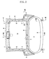
FIG. 2 is a plan view of an inner panel. -
FIG. 3 is a sectional view taken along the line III-III ofFIG. 2 . -
FIG. 4 is an enlargement of a major part ofFIG. 3 . -
FIG. 5 is a sectional view taken along the line V-V ofFIG. 2 . -
FIG. 6 is a sectional view taken along the line VI-VI ofFIG. 2 . -
FIG. 7 is a view illustrating a striker attached to a vehicle body. -
FIG. 8 is a sectional view taken along the line VIII-VIII ofFIG. 2 . -
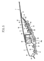
FIG. 9 is an oblique view illustrating a wire arrangement. -
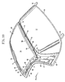
FIG. 10 is an oblique view illustrating the wire arrangement. -
FIG. 11 is a side view illustrating the wire arrangement. -
FIG. 12 is an enlargement of a major part ofFIG. 10 . -
FIG. 13 is a plan view illustrating the wire arrangement. -
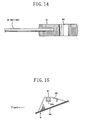
FIG. 14 is a sectional view illustrating a relationship between the wire and a wire mounting part. -
FIG. 15 is a view illustrating a rib. -
FIG. 16 is a sectional view taken along the line XVI-XVI ofFIG. 11 . -
FIG. 17 is a view illustrating a rib. -
FIG. 18 is a view illustrating another example of the rib. -
FIG. 1 illustrates a convertible 6 to which the panel of the present invention is applied. The convertible 6 includes afront windshield 3 surrounded by left and right front pillars 1 and afront header 2, up-and-down side windows 4 and arear deck 5. Further, a hard roof 7 (detachable hardtop) storing therein an open/close hood (not shown) is attached to the convertible 6. - The
hard roof 7 includes anouter panel 8 which forms part of the outer surface of the vehicle and aninner panel 9 integrally bonded to the cabin side of theouter panel 8. Thepanels - As shown in
FIGS. 2 and9 to 11, theinner panel 9 includes afront side part 9A extending in the vehicle width direction, arear side part 9B extending in the vehicle direction at a position more rearward than thefront side part 9A, abottom side part 9C extending in the vehicle width direction at a position more rearward than therear side part 9B,flank side parts 9D extending in the longitudinal direction of the vehicle body to connect the ends of theside part 9A and the ends of theside parts 9B andvertical side parts 9E extending in the vertical direction to connect the ends of theside parts side 9C. Thus, theinner panel 9 includes theintegral side parts 9A to 9E. - The
inner panel 9 further includes anopening 10 defined by thefront side part 9A,rear side part 9B and left and rightflank side parts 9D and anopening 11 defined by therear side part 9B,bottom side part 9C and the left and rightvertical side parts 9E. Theopening 10 is provided for weight reduction. Arear windshield 12 is attached to the rim of the opening 11 (seeFIG. 3 ). - The
hard roof 7 is detachably attached to the vehicle body with use of atop lock 13,wedges 14, side locks 15, and rear deck locks 16. - As shown in
FIGS. 2 to 4 , thetop lock 13 is attached to the middle of thefront side part 9A in the vehicle width direction. Thetop lock 13 includes ahook 18, acover 19 and abase 20. Thehook 18 is detachably engaged with an engagement pin (not shown) attached to thefront header 2 by the operation of alever 17. Details of thetop lock 13 are disclosed byJapanese Examined Utility Model Publication No. 07-28023 - The
base 20 is attached to thefront side part 9A withbolts 21 and nuts 22. Asteel reinforcement 23 is bonded in advance to the middle of the upper surface of thefront side part 9A. Thebase 20,front side part 9A andreinforcement 23 are fastened together with the above-describedbolts 21 and nuts 22. - Referring to
FIG. 3 , a trim 24 (top ceiling) covers the opening 10 from the cabin side and a trim 25 (rear trim) covers thebottom side part 9C of theinner panel 9 from the cabin side. - The
wedges 14 are attached to both ends of thefront side part 9A from the bottom surface, respectively. Each of thewedges 14 includes twopositioning pins tip 29 covered with arubber piece 28. Each of thewedges 14 properly positioned by the positioning pins 26 and 27 is attached to thefront side part 9A withbolts 30 and nuts 31.Steel reinforcements 32 are bonded in advance to both ends of thefront side part 9A from the top surface, respectively. Each of thewedges 14 is fastened together with thefront side part 9A and thereinforcement 32 with thebolts 30 and the nuts 31. - As shown in
FIG. 9 , thereinforcements 32 are arranged at the corners formed by thefront side part 9A and theflank side parts 9D to contact both of theside parts - As shown in
FIG. 5 , thefront header 2 includes a headerouter panel 33 and a headerinner panel 34 which are bonded together to provide therebetweenclosed header space 35 extending in the vehicle width direction. A sealing member 36 is attached to a bonding flange of thefront header 2.Supports 39 are fixed to the headerinner panel 34 withbolts 37 andnuts 38 to receive thewedges 14, respectively. Each of thesupports 39 has arecess 39a for receiving the wedgedtip 29 of thewedge 14, thereby positioning thehard roof 7 at two side parts with respect to the vehicle body. - The side locks 15 are attached to the
vertical side parts 9E, respectively, as shown inFIGS. 2 and6 . Each of the side locks 15 includes ahook 42, a taperedpositioning pin 43 and abase 44. Thehook 42 is locked/unlocked by ahandle 41 which rotates around apivot 40. Thebase 44 is attached to thevertical side part 9E with two ormore bolts 45 and two or more nuts 46 (inFIG. 6 , only a single bolt and nut pair is shown).Steel reinforcements 47 are bonded in advance to the outer surface of thevertical side parts 9E, respectively. Thebase 44,vertical side part 9E and thereinforcement 47 are fastened together with thebolts 45 and the nuts 46. - Each of the
reinforcements 47 extends upward as shown inFIG. 9 such that the top thereof approaches the corner formed by theside parts - Referring to
FIG. 6 , a trim 48 covers thevertical side part 9E of theinner panel 9 from the cabin side. The trim 48 may be integral with the trim 24 shown inFIG. 3 .Reference numeral 49 indicates a weatherstrip. - To the vehicle body,
strikers 50 corresponding to the side locks 15 are fixed. Each of thestrikers 50 includes ahook hole 51 and atapered hole 52 as shown inFIG. 7 . When the taperedpin 43 of theside lock 15 is inserted into the taperedhole 52 and thehook 42 is engaged with thehook hole 51, the bottom side parts of thehard roof 7 are engaged with the center pillar of the vehicle body. - The rear deck locks 16 are attached to the
bottom side part 9C to be spaced from each other in the vehicle width direction. Each of the rear deck locks 16 includes abase plate 54 having anopening 53, alock plate 56 fixed to the rear part of thebase plate 54 from above with aspacer 55 sandwiched therebetween and acover 57. A front portion of thebase plate 54 is inserted into thebottom side part 9C of theinner panel 9. - The
rear deck 5 has engagement pins 58 (lock pins) each having ahead 58a. In order to engage the rear deck locks 16 with the engagement pins 58, respectively, the engagement pins 58 are inserted into theopenings 53 of the rear deck locks 16 and the rear deck locks 16 are shifted forward with the engagement pins 58 and theheads 58a kept protruding upward from theopenings 53. By so doing, the engagement pins 58 are engaged with thelock plates 56. Thus, the left and right sides of the rear part of thehard roof 7 are engaged with the vehicle body. - Referring to
FIG. 8 , a sealingmember 59 is provided around the circumference of therear windshield 12 and aweatherstrip 60 is attached to a projection extending from abottom side part 9C of theinner panel 9. - In the
hard roof 7, a linear reinforcement W is arranged between the outer andinner panels FIGS. 9 to 13 illustrate the arrangement of the linear reinforcement W. The linear reinforcement W is arranged along at least part of the circumference of theinner panel 9, i.e., along thefront side part 9A,flank side parts 9D andrear side part 9B to be substantially in the form of a closed loop. -
FIG. 13 is a plan view illustrating the extraction of the linear reinforcement W. The linear reinforcement W includes discontinuous 10 line segments (wires W1to W6). The wires W1, W3 and W5 are arranged more upward than the wires W2, W4 and W6. - As clearly observed in
FIG. 13 , the arrangement of the wires W1 to W6 is left-right symmetric when viewed in plan. - Each of the wires W1 to W6 has
wire brackets 61 at both ends thereof. Each of thewire brackets 61 is formed by casting with the wire end placed in a casting mold. Thewire brackets 61 have mountingholes 62, respectively. - The
wire brackets 61 of the wires W1 to W6 are fixed to thereinforcements - As shown in
FIG. 9 , the wires W1 and W2 are arranged along thefront side part 9A of theinner panel 9 between thereinforcements reinforcements 23 and the others are fixed to thereinforcements 32. - The wires W2 located below the wires W1 extend linearly along the
front side part 9A of theinner panel 9 between thereinforcements recesses 64a of ribs 64 (seeFIG. 15 ) which are integral with theinner panel 9 and positioned close to thereinforcements - The upper and lower wires W1 and W2 are placed in
space 65 formed between the outer andinner panels 8 and 9 (seeFIGS. 4 and5 ). In order to prevent unusual sounds from occurring, other parts of the wires W1 and W2 than the fixed ends are free from contact with thepanels - As shown in
FIGS. 9 to 12 , the wires W3 and W4 are arranged along theflank side parts 9A of theinner panel 9 between thereinforcements reinforcements 32 and the others are fixed to thereinforcements 47. - At each of the
flank side parts 9D, tworibs 66 are integrally protrude from theinner panel 9 between thereinforcements ribs 66 has anupper recess 67 and alower recess 68 as shown inFIG. 16 . - The wires W3 above the wires W4 are supported by the
upper recesses 67 of theribs 66, while the wires W4 below the wires W3 are supported by thelower recesses 68 of theribs 66. - Specifically, in
space 69 formed between thepanels 8 and 9 (seeFIG. 16 ), the wires W3 and W4 are hooked on therecesses ribs 66. As a result, the wires W3 and W4 are supported with a possible tension applied thereto. Therefore, other parts of the wires W3 and W4 than the fixed ends are free from contact with thepanels - As shown in
FIG. 12 , the upper andlower recesses hard roof 7. Parts of the upper and lower wires W3 and W4 between thefront rib 66 and thereinforcement 32 are arranged nonparallel to each other, and so are parts of the wires W3 and W4 between therear rib 66 and thereinforcement 47. - The
ribs 66 are formed neartrim mounting holes 70 formed in theinner panel 9 as shown inFIGS. 11 and12 . - Mounting bosses of the trim 24 protrude from the cabin side of the
inner panel 9 to the outside through the trim mounting holes 70. The trim 24 is fixed to theinner panel 9 by fittingfasteners 71 on the bosses. As shown inFIGS. 11 and12 , thefasteners 71 are positioned between the upper and lower wires W3 and W4 and do not contact with any of the wires W3 and W4. - As shown in
FIGS. 10 and12 , the wires W5 and W6 are arranged along therear side part 9B between the left andright reinforcements 47 while ones of the ends thereof are fixed to theleft reinforcements 47 and the others are fixed to theright reinforcements 47. - Two or more
integral ribs 72 are formed at the top of thevertical side parts 9E and two or moreintegral ribs 73 are formed at therear side part 9B. Each of theribs recesses FIG. 17 ). - The wires W5 above the wires W6 are supported by the
recesses 73a, while the wires W6 below the wires W5 are supported by therecesses 73b. - The wires W5 and W6 are supported by the
ribs panels panels - Thus, even if the
hard roof 7 is broken under a large load in a collision, thehard roof 7 is prevented from being disassembled or scattered in pieces because the wires W1 to W6 are arranged within thehard roof 7. Further, since the wires W1 to W6 are spaced from thepanels ribs outer panels - The mounting parts (
top lock 13,wedges 14, side locks 15 and rear deck locks 16) are connected via the wires W1 to W6. Therefore, when a large load is applied to thehard roof 7 in a collision, the load transferred from the vehicle body to the mounting parts is dispersed among the mounting parts. Even if a portion of thehard roof 7 close to any of the mounting parts is broken, the scattering of thehard roof 7 is prevented because the mounting part is connected to the other mounting parts via the wires W1 to W6. - The
wedges 14 arranged at the widthwise ends of thehard roof 7 are connected to each other in the vehicle width direction through the wires W1 and W2 and thereinforcements hard roof 7 are connected to each other in the vehicle width direction through the wires W5 and W6 and thereinforcements 47. Therefore, when a large load is applied to any one of thewedges 14 or any one of the side locks 15 in a side or offset collision, the load is dispersed effectively. - The
wedges 14 and the side locks 15 arranged to be spaced from each other in the longitudinal direction of the vehicle body are connected through the wires W3 and W4 and thereinforcements wedges 14 or the side locks 15 in a frontal or rear collision, the load is dispersed effectively. - The
wedges 14 and the side locks 15 attached to thehard roof 7 at different heights are connected to each other through the wires W3 and W4 and thereinforcements wedges 14 or the side locks 15 in a collision, the load is dispersed effectively. - The ends of the wires W1 to W6 are connected to the
top lock 13,wedges 14 andside locks 15 through thereinforcements reinforcements - Further, with use of the
reinforcements hard roof 7 with improved firmness. - Moreover, the wires W1 to W6 and the mounting parts are connected easily in the manufacture of the
hard roof 7. - The linear reinforcement W is arranged along the
side parts - The closed loop is formed of the wires W1 to W6. Both ends of each of the wires W1 to W6 are fixed with bolt and nut pairs 63, respectively. As the number of the bolt and nut pairs 63 fixing the linear reinforcement increases, the applied load is easily dispersed. Therefore, the
hard roof 7 improves in resistance against the impact load. - Further, since the linear reinforcement W has a twinned structure including the upper wires W1, W3, and W5 and the lower wires W2, W4 and W6, the hard roof further improves in resistance against the impact load.
- Moreover, since the wires W1 to W6 are connected together via the
reinforcements - The wires W1 to W6 are supported by the
recesses ribs ribs hard roof 7 is formed by arranging the wires W1 to W6 and then bonding the outer andinner panels - The bolt and nut pairs 63 fixing the front ends of the wires W3 and W4 and those fixing the rear ends are positioned lower than the
recesses ribs 66. Specifically, parts of the wires W3 and W4 between theribs 66 and the fixed ends are skewed to each other (the two wires W3 and W4 are not parallel and do not intersect each other). - More specifically, the direction of extension of the wires W3 and W4 are three-dimensionally changed by the
recesses recesses ribs 66. - The
ribs 66 are arranged near thetrim mounting holes 70 formed in theinner panel 9. Therefore, theribs 66 also serve as reinforcement for the trim mounting holes 70. As a result, the rigidity of thehard roof 7 improves and the trim is attached with high firmness. -
FIG. 18 illustrates another embodiment of the rib. Tworecesses recesses - The arrangement of the linear reinforcement W is not particularly limited to the one described above and may be changed as required.
- The present invention is not limited to the
hard roof 7. For example, the present invention may be applied to a vehicle panel as a component of the vehicle body such as a lift gate or a rear gate. - The present invention is not limited to the embodiments described herein and variations may be made without departing from the major features of the present invention. In every respect, the embodiments described herein are to be regarded as illustrative rather than restrictive. The scope of the present invention is defined by the claims and is not restricted by the description of the specification. Further, it is expressly intended that all such variations, changes and equivalents which fall within the scope of the present invention as defined in the claims, be embraced thereby.
Claims (17)
- A vehicle panel comprising:a panel (7) prepared by bonding an outer panel (8) and an inner panel (9); and a linear reinforcement (W) arranged between the outer panel (8) and the inner panel (9),
characterized in thatthe outer panel (8) or the inner panel (9) includes two or more fixing parts (63) for fixing the linear reinforcement (W) and at least one projection (64, 66, 72, 73) provided between the fixing parts (63) andthe linear reinforcement (W) is in the form of a wire and is supported by the projection (64, 66, 72, 73) between the fixing parts (63) to be spaced from the outer and inner panels (8, 9) while tension is applied to the linear reinforcement (W). - The vehicle panel according to claim 1, whereinthe panel (7) includes two or more mounting parts (13, 14, 15, 16) and is detachably attached to a vehicle body with the mounting parts (13, 14, 15, 16) andthe linear reinforcement (W) connects the mounting parts (13, 14, 15) together.
- The vehicle panel according to claim 2, wherein
the linear reinforcement (W) connects the mounting parts (14, 15) which are arranged at both ends of the panel (7) in the vehicle width direction. - The vehicle panel according to claim 2 or 3, wherein
the linear reinforcement (W) connects the mounting parts (14, 15) which are arranged to be spaced from each other in the longitudinal direction of the vehicle body. - The vehicle panel according to any one of claims 2 to 4, wherein
the linear reinforcement (W) connects the mounting parts (14, 15) which are arranged at different heights. - The vehicle panel according to any one of claims 2 to 5, wherein
the linear reinforcement (W) is connected to the mounting parts (13, 14, 15) via plate-like reinforcements (23, 32, 47). - A vehicle panel according to any one of claims 2 to 6, wherein
the linear reinforcement (W) is arranged along almost the entire circumference of the panel (7). - The vehicle panel according to any one of claims 2 to 7, wherein
the linear reinforcement (W) includes an upper linear reinforcement (W1, W3, W5) and a lower linear reinforcement (W2, W4, W6). - The vehicle panel according to claim 1, wherein
the linear reinforcement (W) is substantially in the form of a closed loop and arranged along at least part of the circumference of the panel (7). - The vehicle panel according to claim 9, whereinthe linear reinforcement (W) is divided into two or more line segments (W1, W2, W3, W4, W5, W6) andboth ends of each of the line segments (W1, W2, W3, W4, W5, W6) are fixed by the fixing parts (63).
- The vehicle panel according to claim 10, wherein
the line segments (W1, W2, W3, W4, W5, W6) include upper line segments (W1, W3, W5) and lower line segments (W2, W4, W6). - The vehicle panel according to claim 10, wherein
the line segments (W1, W2, W3, W4, W5, W6) are connected together via the plate-like reinforcements (23, 32, 47) attached to the outer panel (8) or the inner panel (9). - The vehicle panel according to claim 1, wherein
the projection (64, 66, 72, 73) is provided with a recess (64a, 67, 68, 73a, 73b) for supporting the linear reinforcement (W). - The vehicle panel according to claim 13, wherein
the direction of extension of the linear reinforcement (W) is changed by the recess (64a, 67, 68, 73a, 73b). - The vehicle panel according to claim 13 or 14, whereinthe linear reinforcement (W) includes an upper linear reinforcement (W3) and a lower linear reinforcement (W4),the projection (66) is provided with two recesses (67, 68) corresponding to the upper and lower linear reinforcements (W3, W4) andthe upper and lower linear reinforcements (W3, W4) are arranged such that parts thereof between the projection (66) and the fixing part (63) are not parallel to each other.
- The vehicle panel according to any one of preceding claims, wherein
the projection (66) is arranged near an opening (70) formed in the outer panel (8) or the inner panel (9). - The vehicle panel according to any one of preceding claims, wherein the panel (7) is a roof detachable from the vehicle body.
Applications Claiming Priority (3)
| Application Number | Priority Date | Filing Date | Title |
|---|---|---|---|
| JP2005085205A JP2006264498A (en) | 2005-03-24 | 2005-03-24 | Detachable roof structure of vehicle |
| JP2005085206A JP4639882B2 (en) | 2005-03-24 | 2005-03-24 | Vehicle panel structure |
| JP2005085207A JP2006264500A (en) | 2005-03-24 | 2005-03-24 | Panel structure for vehicle |
Publications (3)
| Publication Number | Publication Date |
|---|---|
| EP1705103A2 EP1705103A2 (en) | 2006-09-27 |
| EP1705103A3 EP1705103A3 (en) | 2007-07-04 |
| EP1705103B1 true EP1705103B1 (en) | 2008-11-26 |
Family
ID=36676546
Family Applications (1)
| Application Number | Title | Priority Date | Filing Date |
|---|---|---|---|
| EP20060003931 Expired - Fee Related EP1705103B1 (en) | 2005-03-24 | 2006-02-27 | Vehicle panel |
Country Status (2)
| Country | Link |
|---|---|
| EP (1) | EP1705103B1 (en) |
| DE (1) | DE602006003789D1 (en) |
Families Citing this family (1)
| Publication number | Priority date | Publication date | Assignee | Title |
|---|---|---|---|---|
| JP7381963B2 (en) * | 2020-02-28 | 2023-11-16 | 日本製鉄株式会社 | Stiffening structure of panel parts |
Family Cites Families (6)
| Publication number | Priority date | Publication date | Assignee | Title |
|---|---|---|---|---|
| DE2006498A1 (en) * | 1970-02-13 | 1971-09-02 | Adam Opel AG, 6090 Russeisheim | Device for protecting the occupants of motor vehicles |
| JPH0534970A (en) | 1991-08-02 | 1993-02-12 | Minolta Camera Co Ltd | Production of electrostatic latent image developing toner |
| DE4208408C2 (en) * | 1992-03-16 | 1994-01-13 | Steyr Daimler Puch Ag | Motor vehicle body with side protection |
| DE19711352C1 (en) | 1997-03-19 | 1998-04-23 | Porsche Ag | Removable hard top for convertible motor vehicle |
| US6135535A (en) * | 1999-12-21 | 2000-10-24 | Larry J. Winget | Removable hard top for an automotive vehicle and method of making a composite removable hard top |
| DE10056796A1 (en) | 2000-11-14 | 2002-05-29 | Volkswagen Ag | Outer skin body panel of plastic for motor vehicles consists of outer and inner parts of duroplastic or thermoplastic formed parts with stiffener elements |
-
2006
- 2006-02-27 DE DE200660003789 patent/DE602006003789D1/en active Active
- 2006-02-27 EP EP20060003931 patent/EP1705103B1/en not_active Expired - Fee Related
Also Published As
| Publication number | Publication date |
|---|---|
| EP1705103A3 (en) | 2007-07-04 |
| DE602006003789D1 (en) | 2009-01-08 |
| EP1705103A2 (en) | 2006-09-27 |
Similar Documents
| Publication | Publication Date | Title |
|---|---|---|
| JP4385582B2 (en) | Vehicle side door structure | |
| JP4259094B2 (en) | Upper body structure of the vehicle | |
| JP3938000B2 (en) | Shock absorbing structure for vehicle side door | |
| JP6090241B2 (en) | Upper body structure of a car with sunroof | |
| US7234764B2 (en) | Mounting structure for sensor covered with step garnish | |
| US9914487B2 (en) | Work vehicle | |
| JP2001219873A (en) | Body lower part structure of vehicle | |
| JP4858048B2 (en) | Lower body structure of automobile | |
| EP1705103B1 (en) | Vehicle panel | |
| JP4225028B2 (en) | Latch mounting structure for vehicle side door | |
| JP4013723B2 (en) | Shock absorbing structure for vehicle side door | |
| JP6674656B2 (en) | Cab structure | |
| JP3846394B2 (en) | Vehicle door structure | |
| US20210387516A1 (en) | Side door structure of vehicle | |
| JP4032725B2 (en) | Lower body structure of automobile | |
| JP4924628B2 (en) | Vehicle side door structure | |
| JP2006264498A (en) | Detachable roof structure of vehicle | |
| JP4639882B2 (en) | Vehicle panel structure | |
| JP4114454B2 (en) | Vehicle side door structure | |
| JP4366112B2 (en) | Rear gate structure of the vehicle | |
| JP3858798B2 (en) | Vehicle side door structure | |
| JP3836023B2 (en) | Vehicle cab structure | |
| JP4305154B2 (en) | Body structure | |
| JP2020040486A (en) | Rear section vehicle body structure of vehicle | |
| JP2006264500A (en) | Panel structure for vehicle |
Legal Events
| Date | Code | Title | Description |
|---|---|---|---|
| PUAI | Public reference made under article 153(3) epc to a published international application that has entered the european phase |
Free format text: ORIGINAL CODE: 0009012 |
|
| AK | Designated contracting states |
Kind code of ref document: A2 Designated state(s): AT BE BG CH CY CZ DE DK EE ES FI FR GB GR HU IE IS IT LI LT LU LV MC NL PL PT RO SE SI SK TR |
|
| AX | Request for extension of the european patent |
Extension state: AL BA HR MK YU |
|
| PUAL | Search report despatched |
Free format text: ORIGINAL CODE: 0009013 |
|
| AK | Designated contracting states |
Kind code of ref document: A3 Designated state(s): AT BE BG CH CY CZ DE DK EE ES FI FR GB GR HU IE IS IT LI LT LU LV MC NL PL PT RO SE SI SK TR |
|
| AX | Request for extension of the european patent |
Extension state: AL BA HR MK YU |
|
| 17P | Request for examination filed |
Effective date: 20071011 |
|
| 17Q | First examination report despatched |
Effective date: 20071214 |
|
| AKX | Designation fees paid |
Designated state(s): DE |
|
| GRAP | Despatch of communication of intention to grant a patent |
Free format text: ORIGINAL CODE: EPIDOSNIGR1 |
|
| GRAS | Grant fee paid |
Free format text: ORIGINAL CODE: EPIDOSNIGR3 |
|
| GRAA | (expected) grant |
Free format text: ORIGINAL CODE: 0009210 |
|
| AK | Designated contracting states |
Kind code of ref document: B1 Designated state(s): DE |
|
| REF | Corresponds to: |
Ref document number: 602006003789 Country of ref document: DE Date of ref document: 20090108 Kind code of ref document: P |
|
| PLBE | No opposition filed within time limit |
Free format text: ORIGINAL CODE: 0009261 |
|
| STAA | Information on the status of an ep patent application or granted ep patent |
Free format text: STATUS: NO OPPOSITION FILED WITHIN TIME LIMIT |
|
| 26N | No opposition filed |
Effective date: 20090827 |
|
| PGFP | Annual fee paid to national office [announced via postgrant information from national office to epo] |
Ref country code: DE Payment date: 20110223 Year of fee payment: 6 |
|
| REG | Reference to a national code |
Ref country code: DE Ref legal event code: R119 Ref document number: 602006003789 Country of ref document: DE Effective date: 20120901 |
|
| PG25 | Lapsed in a contracting state [announced via postgrant information from national office to epo] |
Ref country code: DE Free format text: LAPSE BECAUSE OF NON-PAYMENT OF DUE FEES Effective date: 20120901 |