EP1704765A1 - Device for mounting and adjustment of an agitating finger for a fertilizer spreader - Google Patents
Device for mounting and adjustment of an agitating finger for a fertilizer spreader Download PDFInfo
- Publication number
- EP1704765A1 EP1704765A1 EP06111389A EP06111389A EP1704765A1 EP 1704765 A1 EP1704765 A1 EP 1704765A1 EP 06111389 A EP06111389 A EP 06111389A EP 06111389 A EP06111389 A EP 06111389A EP 1704765 A1 EP1704765 A1 EP 1704765A1
- Authority
- EP
- European Patent Office
- Prior art keywords
- finger
- stirring
- shaft
- adjustment
- drive shaft
- Prior art date
- Legal status (The legal status is an assumption and is not a legal conclusion. Google has not performed a legal analysis and makes no representation as to the accuracy of the status listed.)
- Withdrawn
Links
Images


Classifications
-
- A—HUMAN NECESSITIES
- A01—AGRICULTURE; FORESTRY; ANIMAL HUSBANDRY; HUNTING; TRAPPING; FISHING
- A01C—PLANTING; SOWING; FERTILISING
- A01C15/00—Fertiliser distributors
- A01C15/005—Undercarriages, tanks, hoppers, stirrers specially adapted for seeders or fertiliser distributors
- A01C15/006—Hoppers
- A01C15/007—Hoppers with agitators in the hopper
-
- B—PERFORMING OPERATIONS; TRANSPORTING
- B65—CONVEYING; PACKING; STORING; HANDLING THIN OR FILAMENTARY MATERIAL
- B65D—CONTAINERS FOR STORAGE OR TRANSPORT OF ARTICLES OR MATERIALS, e.g. BAGS, BARRELS, BOTTLES, BOXES, CANS, CARTONS, CRATES, DRUMS, JARS, TANKS, HOPPERS, FORWARDING CONTAINERS; ACCESSORIES, CLOSURES, OR FITTINGS THEREFOR; PACKAGING ELEMENTS; PACKAGES
- B65D88/00—Large containers
- B65D88/54—Large containers characterised by means facilitating filling or emptying
- B65D88/64—Large containers characterised by means facilitating filling or emptying preventing bridge formation
- B65D88/68—Large containers characterised by means facilitating filling or emptying preventing bridge formation using rotating devices
Definitions
- the field of the invention is that of the granular product flow distribution, for example the fertilizer distributors.
- the invention relates to an agitator device present in the hopper of such a spreader, intended to facilitate and / or optimize the flow of its contents, fertilizer or semi for example.
- FIG. 1 A simplified cross-sectional view of such a spreader is shown in FIG. 1, which represents the prior art.
- These spreaders generally consist of one or more hoppers containing the fertilizer to be spread.
- Spreading discs 6 are located directly above the outlet 5 of the hoppers.
- the hoppers 5 each have openings 51 which allow the fertilizer to fall by gravity onto the spreading discs 6.
- the spreading discs 6 are rotated by drive means 61 and project the fertilizer poured onto discs 6 in the vicinity in the form of a spreading sheet, using the centrifugal force.
- FIG. 2 represents the prior art.
- This stirring system comprises an oscillating stirring finger 1 mounted in each hopper so that the end of the finger 1 is above the opening 51.
- the stirring finger is connected to a transmission shaft 2, itself linked to a drive means 21 which transmits a rotary back and forth motion. This rotary back and forth movement is transmitted to the stirring fingers 1, whose end 13 then moves on arcs of circle centered on the axis of the drive shaft.
- a stirring system is described in particular in the patent document EP 0 225 836 in the name of the plaintiff.
- the stirring finger 1 comprises an attachment portion 11 intended to be substantially parallel to the shaft 2.
- the assembly of the stirring finger 1 to the drive shaft 2 is then done by clamping the portion of the 11 against the shaft 2, by means of a connecting mechanism 3.
- the link mechanism 3 to adjust the horizontal position of the stirring finger 1 in the direction indicated by the arrow A, tightening the portion attachment 11 of the stirring finger 1 more or less close to the end of the shaft 2.
- the connecting mechanism 3 for clamping the attachment portion 11 of the stirring finger 1 on the shaft 2 is of rather complex use. Indeed, it includes many elements and requires for each setting many operations of screwing and unscrewing.
- the adjustments made must often be checked by the operator of the agricultural machine. Indeed, the latter being subjected to many shocks and to many vibrations, the adjustment values are frequently subjected to untimely variations in the working phase in the field.
- the invention particularly aims to overcome these disadvantages of the prior art.
- an object of the invention is to provide a connecting piece for mounting a stirring finger on a shaft in the hopper of a fertilizer spreader, which allows a particularly easy and accurate adjustment of the position of the stirring finger.
- An essential objective of the invention is in particular to allow the user to adjust the position of the stirring finger in different directions at a single point.
- Another object of the invention is to provide such a part which avoids any risk of maladjustment during the work phase.
- a further object of the invention is to provide a part allowing adjustment in another direction than those defined by arrows A and B.
- Another object of the invention is to provide a part that is more reliable because it involves fewer elements.
- Yet another object of the invention is to provide such a part which is easy to manufacture and inexpensive.
- a stirrer of a product contained in a hopper facilitating the gravity flow of this product through an opening at the bottom of the hopper
- the agitator comprising an agitating finger secured to a drive shaft, the drive shaft transmitting to the stirring finger an oscillating movement about an average position, such that the end of said finger moves. on an arc of a circle, centered on the axis of the drive shaft.
- such an agitator allows a first adjustment of the end of the stirring finger in a direction C substantially perpendicular to the axis of the drive shaft so as to precisely adjust its position relative to the opening.
- the height position of the end of the agitator above the opening and the hopper can therefore be adjusted, which makes it possible to regulate the effectiveness of the agitation.
- it allows a third adjustment of the angle formed between the stirring finger in the middle position and the vertical.
- a single connecting piece ensuring the fastening of the finger to the shaft allows the first, second and third adjustments.
- the connecting piece comprises a locking slot intended to receive at least a portion of a fixing tooth of the stirring finger to lock it by clamping.
- This embodiment makes it possible to easily adjust the height of the position of the stirring finger.
- the tightening of the fixing tooth is ensured by a screw-nut assembly and / or a clamping lever.
- the connecting piece comprises a sleeve for receiving the end of the drive shaft.
- This sleeve makes it possible to simultaneously perform the second and third adjustments of the position of the stirring finger.
- the sleeve is able to receive clamping means (5, 51) that can collaborate with at least one flat (22) of said drive finger (2) for modifying and locking the inclination of said shaft (2) inside said sleeve (42).
- the stirring finger secured to the drive arm by means of the slot (41) is selected from at least two stirring fingers having different properties.
- the user can thus, very easily, change the stirring finger according to, for example, the product he must spread.
- the invention therefore proposes a novel and inventive control technique of an agitator placed in the hopper of a fertilizer spreader, allowing a reliable and very precise adjustment of the position of the stirring finger in three directions, by means of a single connecting piece.
- a fertilizer distributor agitator conventionally comprises a stirring finger 1 which is secured to a drive shaft 2. According to the invention, this connection is ensured by a single connecting piece 4, as represented in FIG. 3 .
- This connecting piece 4 effectively maintains the stirring finger through a locking slot 41 ensuring its adjustment and / or locking.
- the attachment portion 11 of the stirring finger 1 in fact comprises a tip 12.
- This tip 12 which is substantially parallel to the end of the stirring finger 1, comes in the locking slot 41.
- a clamping system which may be for example a screw nut system or a conventional lever clamping system, then comes close to the two sides of the locking slot 41, blocking the lock firmly. tip 12.
- the second part of the connecting piece 4 forms a sleeve 42 adapted to be fitted on the end of the drive shaft 2.
- the end of the shaft 2 comprises at least two flats 22.
- two housings 43 are provided to receive two nuts 51.
- Two screws 5 are screwed into these nuts, and bear against the flats 22 of the shaft 2, to ensure the clamping of the shaft 2 on the sleeve 42. These screws can be actuated from the outside of the sleeve 42.
- the axes of these screws 5 are eccentric with respect to the axis of the driving shaft 2 2.
- the screwing and unscrewing of these screws on the flats 22 thus make it possible to modify the angle formed by the connecting piece 4 with the drive shaft 2.
- the user can, by acting on these screws 5, adjust the position of the end 13 of the stirring tooth 1 in the direction represented by the arrow B of FIG.
- the user can also depress the sheath 42 more or less on the shaft 2, resulting in an adjustment of the position of the end of the tooth in the direction indicated by the arrow A.
- the user now has the possibility of varying the depression of the tip 12 of the stirring finger 1 in the slot 41, which has the effect of varying the position of the end of the stirring finger in the direction indicated by the arrow C.
- the user can therefore adjust in a particularly precise and easy way the position of the end 13 of the tooth, all the settings along the 3 directions A, B and C being further centralized on a single piece, which, because of the in particular its shape and its design also makes it possible to avoid untimely disturbances of the position of the agitator finger of the hopper, in the face of the vibrations and shocks suffered by the latter, when the agricultural machine is in the working phase in a field .
Landscapes
- Life Sciences & Earth Sciences (AREA)
- Engineering & Computer Science (AREA)
- Mechanical Engineering (AREA)
- Soil Sciences (AREA)
- Environmental Sciences (AREA)
- Fertilizing (AREA)
Abstract
Description
Le domaine de l'invention est celui de la distribution par écoulement de produit en grains, par exemple les distributeurs d'engrais.The field of the invention is that of the granular product flow distribution, for example the fertilizer distributors.
Plus précisément, l'invention concerne un dispositif d'agitateur présent dans la trémie d'un tel épandeur, destiné à faciliter et/ou optimiser l'écoulement de son contenu, engrais ou semi par exemple.More specifically, the invention relates to an agitator device present in the hopper of such a spreader, intended to facilitate and / or optimize the flow of its contents, fertilizer or semi for example.
La distribution de produit en vrac, et notamment de l'engrais, sur les terres agricoles est généralement faite par des épandeurs centrifuges attelés sur des tracteurs agricoles. Une vue en coupe simplifiée d'un tel épandeur est représentée par la figure 1, qui représente l'art antérieur.The distribution of bulk produce, including fertilizer, on agricultural land is usually done by centrifugal spreaders coupled to agricultural tractors. A simplified cross-sectional view of such a spreader is shown in FIG. 1, which represents the prior art.
Ces épandeurs sont généralement constitués d'une ou de plusieurs trémies 5 contenant l'engrais à épandre. Des disques d'épandage 6 sont situés à l'aplomb de la sortie 5 des trémies.These spreaders generally consist of one or more hoppers containing the fertilizer to be spread. Spreading
Les trémies 5 comportent chacune des ouvertures 51 qui permettent à l'engrais de tomber par gravité sur les disques d'épandage 6. Les disques d'épandage 6 sont entraînés en rotation par des moyens d'entraînement 61 et projettent l'engrais versé sur les disques 6 aux alentours sous la forme d'une nappe d'épandage, en utilisant la force centrifuge.The
Pour favoriser un écoulement continu du contenu de la trémie vers l'ouverture 51 de cette dernière, il a été ajouté dans celle-ci un système d'agitation. Un système d'agitation classiquement utilisé est représenté par la figure 2, qui représente l'art antérieur. Ce système d'agitation comprend un doigt d'agitation oscillant 1, monté dans chaque trémie de façon à ce que l'extrémité du doigt 1 se trouve au-dessus de l'ouverture 51.To promote a continuous flow of the contents of the hopper to the opening 51 of the latter, it has been added therein a stirring system. A stirring system conventionally used is shown in FIG. 2, which represents the prior art. This stirring system comprises an oscillating stirring
Le doigt d'agitation est lié à un arbre de transmission 2, lui-même lié à un moyen d'entraînement 21 qui lui transmet un mouvement de va-et-vient rotatif. Ce mouvement de va-et-vient rotatif est transmis aux doigts d'agitation 1, dont l'extrémité 13 se déplace alors sur des arcs de cercle centrés sur l'axe de l'arbre d'entraînement. Un tel système d'agitation est notamment décrit dans le document de brevet
Le doigt d'agitation 1 comprend une portion d'attache 11 destinée à être sensiblement parallèle à l'arbre 2. L'assemblage du doigt d'agitation 1 à l'arbre d'entraînement 2 se fait alors par serrage de la portion d'attache 11 contre l'arbre 2, par le biais d'un mécanisme de liaison 3. Le mécanisme de liaison 3 permet de régler la position horizontale du doigt d'agitation 1 suivant la direction indiquée par la flèche A,en serrant la portion d'attache 11 du doigt d'agitation 1 plus ou moins près de l'extrémité de l'arbre 2. Il est également possible de régler la position angulaire du doigt d'agitation 1 suivant la flèche B, en agissant sur l'arbre 2 de transmission 2 avec le moyen d'entraînement 21. Ce réglage de la position du doigt d'agitation 1 est essentiel. En effet, dans le cas des épandeurs centrifuges à deux trémies, il faut que les doigts d'agitation des deux trémies soient réglés précisément de la même façon pour que les deux trémies déversent exactement la même quantité de produit. Ce réglage est primordial pour pouvoir répartir l'engrais de façon régulière sur la surface agricole.The stirring
La technique connue de l'art antérieur ne permet d'effectuer ce réglage que de façon imparfaite. En effet, le doigt d'agitation ne peut être réglé que suivant deux directions représentées par les flèches A et B de la figure 1.The technique known from the prior art makes it possible to perform this adjustment only imperfectly. Indeed, the stirring finger can be adjusted only in two directions represented by the arrows A and B of FIG.
De plus, le mécanisme de liaison 3 permettant le serrage de la portion d'attache 11 du doigt d'agitation 1 sur l'arbre 2 est d'utilisation assez complexe. En effet, il comprend de nombreux éléments et nécessite pour chaque réglage de nombreuses opérations de vissage et de dévissage.In addition, the
En outre, les réglages effectués doivent être souvent vérifiés par l'opérateur de la machine agricole. En effet, cette dernière étant soumise à de nombreux chocs et à de nombreuses vibrations, les valeurs de réglage sont fréquemment soumises à des variations intempestives en phase de travail dans le champ.In addition, the adjustments made must often be checked by the operator of the agricultural machine. Indeed, the latter being subjected to many shocks and to many vibrations, the adjustment values are frequently subjected to untimely variations in the working phase in the field.
L'invention a notamment pour objectif de pallier ces inconvénients de l'art antérieur.The invention particularly aims to overcome these disadvantages of the prior art.
Plus précisément, un objectif de l'invention est de fournir une pièce de liaison permettant le montage d'un doigt d'agitation sur un arbre dans la trémie d'un épandeur d'engrais, qui permette un réglage particulièrement facile et précis de la position du doigt d'agitation.More specifically, an object of the invention is to provide a connecting piece for mounting a stirring finger on a shaft in the hopper of a fertilizer spreader, which allows a particularly easy and accurate adjustment of the position of the stirring finger.
Un objectif essentiel de l'invention est notamment de permettre à l'utilisateur de régler la position du doigt d'agitation dans différentes directions en un point unique.An essential objective of the invention is in particular to allow the user to adjust the position of the stirring finger in different directions at a single point.
Un autre objectif de l'invention est de fournir une telle pièce qui évite tout risque de déréglage en phase de travail.Another object of the invention is to provide such a part which avoids any risk of maladjustment during the work phase.
Un objectif supplémentaire de l'invention est de fournir une pièce permettant un réglage dans une autre direction que celles définies par les flèches AetB.A further object of the invention is to provide a part allowing adjustment in another direction than those defined by arrows A and B.
Un autre objectif de l'invention est de fournir une pièce qui soit plus fiable car impliquant moins d'éléments.Another object of the invention is to provide a part that is more reliable because it involves fewer elements.
Encore un autre objectif de l'invention est de fournir une telle pièce qui soit facile à fabriquer et peu coûteuse.Yet another object of the invention is to provide such a part which is easy to manufacture and inexpensive.
Ces objectifs, ainsi que d'autres qui apparaîtront par la suite, sont atteints à l'aide d'un agitateur d'un produit contenu dans une trémie facilitant l'écoulement par gravité de ce produit par une ouverture se trouvant au fond de la trémie, l'agitateur comprenant un doigt d'agitation solidarisé à un arbre d'entraînement, l'arbre d'entraînement transmettant au doigt d'agitation un mouvement oscillant autour d'une position moyenne, tel que l'extrémité dudit doigt se déplace sur un arc de cercle, centré sur l'axe de l'arbre d'entraînement.These objectives, as well as others that will appear later, are achieved with the aid of a stirrer of a product contained in a hopper facilitating the gravity flow of this product through an opening at the bottom of the hopper, the agitator comprising an agitating finger secured to a drive shaft, the drive shaft transmitting to the stirring finger an oscillating movement about an average position, such that the end of said finger moves. on an arc of a circle, centered on the axis of the drive shaft.
Selon l'invention, un tel agitateur permet un premier réglage de l'extrémité du doigt d'agitation selon une direction C sensiblement perpendiculaire à l'axe de l'arbre d'entraînement de façon à régler précisément sa position par rapport à l'ouverture.According to the invention, such an agitator allows a first adjustment of the end of the stirring finger in a direction C substantially perpendicular to the axis of the drive shaft so as to precisely adjust its position relative to the opening.
La position en hauteur de l'extrémité de l'agitateur au-dessus de l'ouverture e la trémie peut donc être ajustée, ce qui permet de régler l'efficacité de l'agitation.The height position of the end of the agitator above the opening and the hopper can therefore be adjusted, which makes it possible to regulate the effectiveness of the agitation.
Avantageusement, il permet un second réglage de la position de l'extrémité du doigt d'agitation selon une direction parallèle à l'axe de l'arbre.Advantageously, it allows a second adjustment of the position of the end of the stirring finger in a direction parallel to the axis of the shaft.
De façon préférentielle, il permet un troisième réglage de l'angle formé entre le doigt d'agitation dans la position moyenne et la verticale.Preferably, it allows a third adjustment of the angle formed between the stirring finger in the middle position and the vertical.
Ces réglages permettre de régler la position de l'agitateur au dessus de l'ouverture de la trémie.These settings make it possible to adjust the position of the agitator above the opening of the hopper.
Selon un mode de réalisation préférentiel de l'invention, une pièce de liaison unique assurant la solidarisation du doigt à l'arbre permet les premier, deuxième et troisième réglages.According to a preferred embodiment of the invention, a single connecting piece ensuring the fastening of the finger to the shaft allows the first, second and third adjustments.
Le réglage de la position du doigt d'agitation est donc considérablement facilité.The adjustment of the position of the stirring finger is thus considerably facilitated.
Avantageusement, la pièce de liaison comprend une fente de blocage destinée à recevoir au moins une partie d'une dent de fixation du doigt d'agitation pour la bloquer par serrage.Advantageously, the connecting piece comprises a locking slot intended to receive at least a portion of a fixing tooth of the stirring finger to lock it by clamping.
Ce mode de réalisation permet de réaliser de façon aisée le réglage en hauteur de la position du doigt d'agitation.This embodiment makes it possible to easily adjust the height of the position of the stirring finger.
Selon un mode de réalisation avantageux, le serrage de la dent de fixation est assuré par un ensemble vis-écrou et/ou un levier de serrage.According to an advantageous embodiment, the tightening of the fixing tooth is ensured by a screw-nut assembly and / or a clamping lever.
Préférentiellement, la pièce de liaison comprend un fourreau destiné recevoir l'extrémité de l'arbre d'entraînement.Preferably, the connecting piece comprises a sleeve for receiving the end of the drive shaft.
Ce fourreau permet de réaliser simultanément les deuxième et troisième réglages de la position du doigt d'agitation.This sleeve makes it possible to simultaneously perform the second and third adjustments of the position of the stirring finger.
Selon un mode de réalisation particulier de l'invention, le fourreau est apte à recevoir des moyens de serrage (5, 51) pouvant collaborer avec au moins un méplat (22) dudit doigt d'entraînement (2), pour modifier et verrouiller l'inclinaison dudit arbre (2) à l'intérieur dudit fourreau (42).According to a particular embodiment of the invention, the sleeve is able to receive clamping means (5, 51) that can collaborate with at least one flat (22) of said drive finger (2) for modifying and locking the inclination of said shaft (2) inside said sleeve (42).
Ces moyens de serrage permettent ainsi un réglage particulièrement précis de la position du doigt d'agitation.These clamping means thus allow a particularly precise adjustment of the position of the stirring finger.
Préférentiellement, le doigt d'agitation solidarisé au bras d'entraînement au moyens de la fente (41) est choisi parmi au moins deux doigts d'agitation ayant des propriétés différentes.Preferably, the stirring finger secured to the drive arm by means of the slot (41) is selected from at least two stirring fingers having different properties.
L'utilisateur pourra ainsi, de façon très facile, changer de doigt d'agitation en fonction, par exemple, du produit qu'il doit épandre.The user can thus, very easily, change the stirring finger according to, for example, the product he must spread.
D'autres caractéristiques et avantages de l'invention apparaîtront plus clairement à la lecture de la description suivante d'un mode de réalisation préférentiel, donné à titre de simple exemple illustratif et non limitatif, et des dessins annexés, parmi lesquels :
- la figure 1 présente l'art antérieur à l'invention et a été commentée ci-dessus ; elle présente une vue en coupe simplifiée d'un épandeur centrifuge d'engrais comprenant deux trémies ;
- la figure 2 présente un système d'agitation selon l'art antérieur, et a également été commentée ci-dessus ;
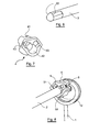
- la figure 3 illustre une pièce de liaison du doigt d'agitation sur l'arbre d'entraînement selon l'invention ;
- la figure 4 donne un schéma de montage du doigt d'agitation sur l'arbre d'entraînement au moyen d'une pièce de liaison selon la figure 3.
- la figure 5 présente un système d'agitation suivant l'invention ;
- la figure 6 illustre un arbre d'entraînement selon l'invention ;
- la figure 7 présente une autre vue de la pièce de liaison de la figure 3 ;
- la figure 8 présente une autre vue du système d'agitation de la figure 5.
- Figure 1 shows the prior art to the invention and was commented on above; it has a simplified sectional view of a centrifugal fertilizer spreader comprising two hoppers;
- Figure 2 shows a stirring system according to the prior art, and has also been commented above;
- Figure 3 illustrates a connecting piece of the stirring finger on the drive shaft according to the invention;
- FIG. 4 gives a circuit diagram of the stirring finger on the drive shaft by means of a connection piece according to FIG. 3.
- Figure 5 shows an agitation system according to the invention;
- Figure 6 illustrates a drive shaft according to the invention;
- Figure 7 shows another view of the connecting piece of Figure 3;
- Figure 8 shows another view of the stirring system of Figure 5.
L'invention propose donc une technique de réglage nouvelle et inventive d'un agitateur placé dans la trémie d'un épandeur d'engrais, permettant un réglage fiable et très précis de la position du doigt d'agitation suivant trois directions, au moyen d'une pièce de liaison unique.The invention therefore proposes a novel and inventive control technique of an agitator placed in the hopper of a fertilizer spreader, allowing a reliable and very precise adjustment of the position of the stirring finger in three directions, by means of a single connecting piece.
Un agitateur de distributeur d'engrais comporte classiquement un doigt d'agitation 1 qui est solidarisé à un arbre d'entraînement 2. Selon l'invention, cette solidarisation est assurée par une pièce de liaison unique 4, telle que représentée sur la figure 3.A fertilizer distributor agitator conventionally comprises a
Cette pièce de liaison 4 maintient efficacement le doigt d'agitation grâce à une fente de blocage 41 assurant son réglage et/ou son verrouillage. Comme le représente la figure 4, la portion d'attache 11 du doigt d'agitation 1 selon l'invention comporte en effet un embout 12. Cet embout 12, qui est sensiblement parallèle à l'extrémité du doigt d'agitation 1, vient s'enficher dans la fente de blocage 41. Un système de serrage, qui peut être par exemple un système vis écrou ou un système classique de serrage à levier, vient alors rapprocher les deux cotés de la fente de blocage 41, en bloquant solidement l'embout 12.This connecting
La deuxième partie de la pièce de liaison 4 forme un fourreau 42 adapté pour venir s'emmancher sur l'extrémité de l'arbre d'entraînement 2. Selon un mode de réalisation particulier de l'invention, représenté par les figures 4, 6, 7 et 8 l'extrémité de l'arbre 2 comporte au moins deux méplats 22.The second part of the connecting
Dans le fourreau 42, deux logements 43 sont prévus pour recevoir deux écrous 51. Deux vis 5 sont vissées dans ces écrous, et viennent en appui contre les méplats 22 de l'arbre 2, pour assurer le serrage de l'arbre 2 sur le fourreau 42. Ces vis peuvent être actionnées depuis la partie extérieure du fourreau 42.In the
Les axes de ces vis 5 sont excentrés par rapport à l'axe de l'arbre 2 d'entraînement 2. Le vissage et le dévissage de ces vis sur les méplats 22 permettent donc de modifier l'angle que forme la pièce de liaison 4 avec l'arbre d'entraînement 2. L'utilisateur peut donc, en agissant sur ces vis 5, ajuster la position de l'extrémité 13 de la dent d'agitation 1 suivant la direction représenté par la flèche B de la figure 5.The axes of these
L'utilisateur peut également enfoncer plus ou moins le fourreau 42 sur l'arbre 2, ce qui entraîne un ajustement de la position de l'extrémité de la dent selon la direction indiquée par la flèche A.The user can also depress the
Dans le mode de réalisation présenté, les serrages se font à l'aide de vis. Il est bien entendu que n'importe quel autre moyen de serrage connu de l'homme du métier peut être utilisé comme variante de ce mode de réalisation préféré de l'invention.In the embodiment shown, the tightenings are made using screws. It is understood that any other clamping means known to those skilled in the art can be used as an alternative to this preferred embodiment of the invention.
Enfm, l'utilisateur a désormais la possibilité de faire varier l'enfoncement de l'embout 12 du doigt d'agitation 1 dans la fente 41, ce qui a pour effet de faire varier la position de l'extrémité du doigt d'agitation selon la direction indiquée par la flèche C.Finally, the user now has the possibility of varying the depression of the
L'utilisateur peut donc régler d'une façon particulièrement précise et facile la position de l'extrémité 13 de la dent, tous les réglages suivant les 3 directions A, B et C étant en outre centralisés sur une seule pièce, laquelle, du fait notamment de sa forme et de sa conception permet également d'éviter des dérèglements intempestifs de la position du doigt d'agitateur de la trémie, face aux vibrations et chocs subis par cette dernière, lorsque la machine agricole est en phase de travail dans un champ.The user can therefore adjust in a particularly precise and easy way the position of the
Claims (9)
caractérisé en ce qu'il permet un premier réglage de l'extrémité dudit doigt d'agitation (1) selon une direction sensiblement perpendiculaire à l'axe dudit arbre d'entraînement (2) de façon à régler précisément sa position par rapport à ladite ouverture (51).Agitator of a product contained in a hopper (5) facilitating the gravity flow of said product through an opening (51) at the bottom of said hopper (5), said stirrer comprising a stirring finger (1) secured to a drive shaft (2), said drive shaft transmitting to said stirring finger (1) a swinging motion about a mean position.
characterized in that it allows a first adjustment of the end of said stirring finger (1) in a direction substantially perpendicular to the axis of said drive shaft (2) so as to precisely adjust its position relative to said opening (51).
Applications Claiming Priority (1)
| Application Number | Priority Date | Filing Date | Title |
|---|---|---|---|
| FR0502785A FR2883265B1 (en) | 2005-03-21 | 2005-03-21 | DEVICE FOR MOUNTING AND ADJUSTING AN AGITATOR FINGER FACILITATING FLOW BY OPENING A PRODUCT CONTAINED IN A HOPPER, IN PARTICULAR FOR A FERTILIZER DISPENSER |
Publications (1)
| Publication Number | Publication Date |
|---|---|
| EP1704765A1 true EP1704765A1 (en) | 2006-09-27 |
Family
ID=35169248
Family Applications (1)
| Application Number | Title | Priority Date | Filing Date |
|---|---|---|---|
| EP06111389A Withdrawn EP1704765A1 (en) | 2005-03-21 | 2006-03-20 | Device for mounting and adjustment of an agitating finger for a fertilizer spreader |
Country Status (2)
| Country | Link |
|---|---|
| EP (1) | EP1704765A1 (en) |
| FR (1) | FR2883265B1 (en) |
Cited By (3)
| Publication number | Priority date | Publication date | Assignee | Title |
|---|---|---|---|---|
| EP2742788A1 (en) * | 2012-12-17 | 2014-06-18 | Amazonen-Werke H. Dreyer GmbH & Co. KG | Spreader device |
| EP3020264A1 (en) * | 2014-11-17 | 2016-05-18 | Amazonen-Werke H. Dreyer GmbH & Co. KG | Spreader |
| EP3326441A1 (en) * | 2016-11-23 | 2018-05-30 | Amazonen-Werke H. Dreyer GmbH & Co. KG | Agricultural spreader with stirring device |
Families Citing this family (1)
| Publication number | Priority date | Publication date | Assignee | Title |
|---|---|---|---|---|
| FR2923675B1 (en) | 2007-11-16 | 2012-10-26 | Sulky Burel | SEMOLINATING THE SIMULTANEOUS DISTRIBUTION OF GRANULAR SEEDS AND ELEMENTS, IN PARTICULAR FERTILIZERS |
Citations (5)
| Publication number | Priority date | Publication date | Assignee | Title |
|---|---|---|---|---|
| GB980371A (en) * | 1962-10-05 | 1965-01-13 | Autopack Ltd | Improvements relating to filling machines |
| DE2835011B1 (en) * | 1978-08-10 | 1980-02-07 | Amazonen Werke Dreyer H | Centrifugal broadcaster, especially for granular fertilizers |
| DE8632954U1 (en) * | 1986-12-09 | 1987-05-21 | Weichs, Hermann, 8267 Neumarkt-St Veit | Spreader driven by tractor hydraulics |
| EP0225836A1 (en) | 1985-10-18 | 1987-06-16 | Sulky-Burel S.A. | Stirrer for distributing loose material by gravity |
| FR2663008A1 (en) * | 1990-06-12 | 1991-12-13 | Goavec Sa | Hopper for dispensing products with lumps |
-
2005
- 2005-03-21 FR FR0502785A patent/FR2883265B1/en not_active Expired - Fee Related
-
2006
- 2006-03-20 EP EP06111389A patent/EP1704765A1/en not_active Withdrawn
Patent Citations (5)
| Publication number | Priority date | Publication date | Assignee | Title |
|---|---|---|---|---|
| GB980371A (en) * | 1962-10-05 | 1965-01-13 | Autopack Ltd | Improvements relating to filling machines |
| DE2835011B1 (en) * | 1978-08-10 | 1980-02-07 | Amazonen Werke Dreyer H | Centrifugal broadcaster, especially for granular fertilizers |
| EP0225836A1 (en) | 1985-10-18 | 1987-06-16 | Sulky-Burel S.A. | Stirrer for distributing loose material by gravity |
| DE8632954U1 (en) * | 1986-12-09 | 1987-05-21 | Weichs, Hermann, 8267 Neumarkt-St Veit | Spreader driven by tractor hydraulics |
| FR2663008A1 (en) * | 1990-06-12 | 1991-12-13 | Goavec Sa | Hopper for dispensing products with lumps |
Cited By (3)
| Publication number | Priority date | Publication date | Assignee | Title |
|---|---|---|---|---|
| EP2742788A1 (en) * | 2012-12-17 | 2014-06-18 | Amazonen-Werke H. Dreyer GmbH & Co. KG | Spreader device |
| EP3020264A1 (en) * | 2014-11-17 | 2016-05-18 | Amazonen-Werke H. Dreyer GmbH & Co. KG | Spreader |
| EP3326441A1 (en) * | 2016-11-23 | 2018-05-30 | Amazonen-Werke H. Dreyer GmbH & Co. KG | Agricultural spreader with stirring device |
Also Published As
| Publication number | Publication date |
|---|---|
| FR2883265A1 (en) | 2006-09-22 |
| FR2883265B1 (en) | 2007-05-25 |
Similar Documents
| Publication | Publication Date | Title |
|---|---|---|
| BE1003991A4 (en) | Combine fitted with a device for the distribution of mixed grains and ball. | |
| EP0046709B1 (en) | Distributing device for pneumatic precision drill | |
| EP1704765A1 (en) | Device for mounting and adjustment of an agitating finger for a fertilizer spreader | |
| FR2902063A1 (en) | Liquid spraying device for windscreen of motor vehicle, has sprinkling head in rotational plane of windscreen wiper arm, and nozzles arranged on lower part of head, where device is connected to distal or free end of arm | |
| FR3030466A3 (en) | ||
| EP1628518B1 (en) | Device for processing fodder | |
| EP1878649B1 (en) | Bicycle crank | |
| EP1605805A1 (en) | Condiment mill | |
| EP0780922B1 (en) | Antirotation device for electric cable terminal and welded assembly of this part with another element | |
| WO2001001831A1 (en) | Hand operated electric whisk/mixer | |
| EP2823701B1 (en) | Seeder element with handle for adjusting the soil pressure | |
| FR3050093A1 (en) | DEVICE FOR DISPENSING GRANULAR MATERIALS AND POWDERS AND AGRICULTURAL MACHINE COMPRISING SUCH A DEVICE | |
| FR2477366A1 (en) | CENTRIFUGAL DISPENSER, ESPECIALLY FOR FERTILIZER SPREADING | |
| FR2810194A1 (en) | DRIVE DEVICE FOR THE DOSING MECHANISM OF A SEEDER AND SEEDER PROVIDED WITH SUCH A DRIVE DEVICE | |
| FR2481568A1 (en) | Metering powder or granular material - by rotary cylinder with projections and wiper arranged to give predictable flow of material cleared | |
| WO2023148348A1 (en) | Wrench for operating a valve | |
| EP2636291A1 (en) | Device for self-adjusting fastening of a device to the frame of a seed drill | |
| EP0224718B1 (en) | Dispenser | |
| EP0914759B1 (en) | Blade mounting assembly for agricultural machine | |
| FR2887472A1 (en) | Rotating coating material spray cup for object to be coated, has body with tapping cooperating with dispenser`s thread, and tapered carrier surfaces supported against each other by screwing of distributor on body by using thread and tapping | |
| EP0796807B1 (en) | Method and device for regulating the advancement speed of a conveyor driven by a hydraulic motor, and fitted to a machine such as a Silage distributor, spreader or the like | |
| EP0916249B1 (en) | Cutting machine | |
| FR2672577A1 (en) | Dispenser for granular or pulverulent products with built-in flow rate control | |
| WO2021130043A1 (en) | Universal load take-up device for dumper wheel rim | |
| FR2475087A1 (en) | SPREADING DEVICE |
Legal Events
| Date | Code | Title | Description |
|---|---|---|---|
| PUAI | Public reference made under article 153(3) epc to a published international application that has entered the european phase |
Free format text: ORIGINAL CODE: 0009012 |
|
| AK | Designated contracting states |
Kind code of ref document: A1 Designated state(s): AT BE BG CH CY CZ DE DK EE ES FI FR GB GR HU IE IS IT LI LT LU LV MC NL PL PT RO SE SI SK TR |
|
| AX | Request for extension of the european patent |
Extension state: AL BA HR MK YU |
|
| 17P | Request for examination filed |
Effective date: 20061106 |
|
| 17Q | First examination report despatched |
Effective date: 20061214 |
|
| AKX | Designation fees paid |
Designated state(s): DE IT |
|
| STAA | Information on the status of an ep patent application or granted ep patent |
Free format text: STATUS: THE APPLICATION IS DEEMED TO BE WITHDRAWN |
|
| 18D | Application deemed to be withdrawn |
Effective date: 20111001 |