EP1703377A2 - Multi-threaded processor - Google Patents
Multi-threaded processor Download PDFInfo
- Publication number
- EP1703377A2 EP1703377A2 EP20060005551 EP06005551A EP1703377A2 EP 1703377 A2 EP1703377 A2 EP 1703377A2 EP 20060005551 EP20060005551 EP 20060005551 EP 06005551 A EP06005551 A EP 06005551A EP 1703377 A2 EP1703377 A2 EP 1703377A2
- Authority
- EP
- European Patent Office
- Prior art keywords
- processor
- thread
- processor thread
- threads
- register
- Prior art date
- Legal status (The legal status is an assumption and is not a legal conclusion. Google has not performed a legal analysis and makes no representation as to the accuracy of the status listed.)
- Withdrawn
Links
- 238000000034 method Methods 0.000 claims abstract description 30
- 238000004891 communication Methods 0.000 claims description 16
- 238000010586 diagram Methods 0.000 description 8
- 239000002131 composite material Substances 0.000 description 1
- 238000013500 data storage Methods 0.000 description 1
- 230000009977 dual effect Effects 0.000 description 1
- 238000012986 modification Methods 0.000 description 1
- 230000004048 modification Effects 0.000 description 1
- 239000000725 suspension Substances 0.000 description 1
Images


Classifications
-
- G—PHYSICS
- G06—COMPUTING; CALCULATING OR COUNTING
- G06F—ELECTRIC DIGITAL DATA PROCESSING
- G06F9/00—Arrangements for program control, e.g. control units
- G06F9/06—Arrangements for program control, e.g. control units using stored programs, i.e. using an internal store of processing equipment to receive or retain programs
- G06F9/30—Arrangements for executing machine instructions, e.g. instruction decode
- G06F9/30098—Register arrangements
- G06F9/3012—Organisation of register space, e.g. banked or distributed register file
- G06F9/30123—Organisation of register space, e.g. banked or distributed register file according to context, e.g. thread buffers
-
- G—PHYSICS
- G06—COMPUTING; CALCULATING OR COUNTING
- G06F—ELECTRIC DIGITAL DATA PROCESSING
- G06F9/00—Arrangements for program control, e.g. control units
- G06F9/06—Arrangements for program control, e.g. control units using stored programs, i.e. using an internal store of processing equipment to receive or retain programs
- G06F9/30—Arrangements for executing machine instructions, e.g. instruction decode
- G06F9/38—Concurrent instruction execution, e.g. pipeline or look ahead
- G06F9/3836—Instruction issuing, e.g. dynamic instruction scheduling or out of order instruction execution
- G06F9/3851—Instruction issuing, e.g. dynamic instruction scheduling or out of order instruction execution from multiple instruction streams, e.g. multistreaming
-
- G—PHYSICS
- G06—COMPUTING; CALCULATING OR COUNTING
- G06F—ELECTRIC DIGITAL DATA PROCESSING
- G06F9/00—Arrangements for program control, e.g. control units
- G06F9/06—Arrangements for program control, e.g. control units using stored programs, i.e. using an internal store of processing equipment to receive or retain programs
- G06F9/30—Arrangements for executing machine instructions, e.g. instruction decode
- G06F9/38—Concurrent instruction execution, e.g. pipeline or look ahead
- G06F9/3861—Recovery, e.g. branch miss-prediction, exception handling
-
- G—PHYSICS
- G06—COMPUTING; CALCULATING OR COUNTING
- G06F—ELECTRIC DIGITAL DATA PROCESSING
- G06F9/00—Arrangements for program control, e.g. control units
- G06F9/06—Arrangements for program control, e.g. control units using stored programs, i.e. using an internal store of processing equipment to receive or retain programs
- G06F9/30—Arrangements for executing machine instructions, e.g. instruction decode
- G06F9/38—Concurrent instruction execution, e.g. pipeline or look ahead
- G06F9/3867—Concurrent instruction execution, e.g. pipeline or look ahead using instruction pipelines
Definitions
- the following disclosure relates to processing circuits and systems.
- a processor thread represents an architectural state within a processor that tracks execution of a software program. In the case of a computer having a single processor, only one processor thread is processed at any given point in time, meaning that the processor is actively executing instructions associated with a single processor thread. The act of re-assigning a processor from one processor thread to another is called a context switch.
- a context switch typically occurs through a hardware interrupt and interrupt service routine.
- Interrupt service routines typically have an associated execution time, or interrupt overhead, that may consume valuable processor time.
- a context switch typically occurs only at fixed intervals (e.g., every 100 ⁇ s), as determined by, e.g., vendors of an operating system.
- this specification describes a processor including a pipeline stage.
- the pipeline stage includes a first input register, a second input register, a first output register, and a second output register.
- the processor further includes a first selector in communication with the first input register and the second input register, and a second selector in communication with the first output register and the second output register.
- the processor also includes a controller operable to control switching of the first and second selectors such that data associated with a first processor thread passes through the first input register, the pipeline stage, and the first output register during a time that the first processor thread is being processed, and data associated with a second processor thread passes through the second input register, the pipeline stage, and the second output register during a time that the second processor thread is being processed.
- the first input register and the first output register are operable to store a state of the first processor thread
- the second input register and the second output register are operable to store a state of the second processor thread.
- the first selector can include a multiplexer and the second selector can include a de-multiplexer.
- the pipeline stage can include one of an instruction fetch unit, decode logic, issue logic, execution unit, read logic, or write logic.
- the controller can control switching of the first and second selectors based on input defining processor time to be allocated to each of the first and the second processor threads.
- the controller can control switching of the first and second selectors dynamically during execution of a program or statically based on a previously established processor time allocation for each of the first and second processor threads.
- the processor can further include a first interrupt handling routine to handle an interrupt request associated with the first processor thread, and a second interrupt handling routine to handle an interrupt request associated with the second processor thread.
- the first interrupt handling routine and the second interrupt handling routine can have separate entry points.
- the processor can further include a first exception handling routine to handle an exception request associated with the first processor thread, and a second exception handling routine to handle an exception request associated with the second processor thread.
- the processor can further include a single exception handling routine or a single interrupt handling routine to respectively handle substantially all exception requests or substantially all interrupt requests associated with both the first and second processor threads.
- the processor can further include a set of registers corresponding to each of a plurality of processor threads. Each register within a set can be located either before or after a pipeline stage of the processor.
- the controller can perform a context switch among the plurality of processor threads, including storing a state of a currently executing processor thread in a corresponding set of registers, and loading a state of another processor thread from a corresponding set of registers to allow for processing of the another processor thread.
- this specification describes a processor including a set of registers corresponding to each of a plurality of processor threads. Each register within a set is located either before or after a pipeline stage of the processor.
- the processor further includes a programmable controller operable to perform a context switch among the plurality of processor threads, including storing a state of a currently executing processor thread in a corresponding set of registers, and loading a state of another processor thread from a corresponding set of registers to allow for processing of the another processor thread.
- the programmable controller can perform the context switch at an end of an instruction cycle.
- the processor can further include a register file having a plurality of banks corresponding to each of the plurality of processor threads. Each bank can store data associated with a corresponding processor thread.
- the processor can further include a plurality of program counters, each program counter operable to indicate an execution status of a corresponding processor thread.
- the processor can further include a plurality of interrupt handling routines corresponding to the plurality of processor threads, in which each interrupt handling routine handles an interrupt request associated with a corresponding processor thread.
- Each of the plurality of interrupt handling routines can have separate entry points.
- the processor can further include a plurality of exception handling routines corresponding to the plurality of processor threads, in which each exception handling routine handles an exception request associated with a corresponding processor thread.
- the processor can include a single exception handling routine or a single interrupt handling routine to respectively handle substantially all exception requests or substantially all interrupt requests associated with the plurality of processor threads.
- this specification describes a method including providing a first processor thread for instruction execution; providing a second processor thread for instruction execution; processing the first processor thread; and performing a context switch from the first processor thread to the second processor thread.
- Performing a context switch includes storing a state of the first processor thread in a first set of registers corresponding to the first processor thread, and loading a state of the second processor thread from a second set of registers corresponding to the second processor thread.
- Storing a state of a given processor thread within a corresponding set of registers can include storing data corresponding to a pipeline stage of a processor.
- the method can further include receiving input changing the processor time allocation, and performing a context switch among the first and second processor threads based on the changed processor time allocation.
- Performing a context switch can include performing a context switch dynamically during execution of a program or statically based on a previously established processor time allocation for each of the first and second processor threads.
- the method can further include using a first interrupt handling routine to handle an interrupt request associated with the first processor thread, and using a second interrupt handling routine to handle an interrupt request associated with the second processor thread.
- the method can further include using a first exception handling routine to handle an exception request associated with the first processor thread, and using a second exception handling routine to handle an exception request associated with the second processor thread.
- the method can further include using a single exception handling routine or a single interrupt handling routine to respectively handle substantially all exception requests and substantially all interrupt requests associated with the first and second processor threads.
- this specification describes a processor including an instruction fetch unit operable to fetch instructions associated with a plurality of processor threads, a decoder responsive to the instruction fetch unit, issue logic responsive to the decoder, and a register file including a plurality of banks corresponding to the plurality of processor threads. Each bank is operable to only store data associated with a corresponding processor thread.
- the data can include operands or results of executed instructions associated with a given processor thread.
- the processor can further include a controller in communication with the instruction fetch unit. The controller can determine a processor thread from which a next instruction will be fetched by the instruction fetch unit.
- the processor can further include a set of registers corresponding to each of the plurality of threads. Each register within a set can be located either before or after a pipeline stage of the processor.
- the controller can perform a context switch among the plurality of processor threads, including storing a state of a currently executing processor thread in a corresponding set of registers, and loading a state of another processor thread from a corresponding set of registers to allow for processing of the another processor thread.
- the controller can include a plurality of thread allocation counters corresponding to the plurality of processor threads. Each thread allocation counter can contain a value representing how much processor time is to be allocated for a respective processor thread.
- the controller can perform a context switch including switching a selector that is in communication with the instruction fetch unit.
- the selector can include a multiplexer or a de-multiplexer.
- this specification describes a processor including means for executing instructions through a pipeline stage.
- the means for executing instructions includes a first input means for storing data, a second input means for storing data, a first output means for storing data, and a second output means for storing data.
- the processor further includes a first means for selecting in communication with the first input means for storing data and the second input means for storing data, and a second means for selecting in communication with the first output means for storing data and the second output means for storing data.
- the processor also includes means for controlling switching of the first and second means for selecting such that data associated with a first processor thread passes through the first input means for storing data, the means for executing, and the first output means for storing data during a time that the first processor thread is being processed, and data associated with a second processor thread passes through the second input means for storing data, the means for executing, and the second output means for storing data during a time that the second processor thread is being processed.
- the first input means for storing data and the first output means for storing data are operable to store a state of the first processor thread
- the second input means for storing data and the second output means for storing data are operable to store a state of the second processor thread.
- this specification describes a processor including means for storing data corresponding to each of a plurality of processor threads. Each means for storing data is located either before or after a stage means of the processor.
- the processor further includes means for performing a context switch among the plurality of processor threads, including means for storing a state of a currently executing processor thread in a corresponding set of means for storing data, and loading a state of another processor thread from a corresponding set of means for storing data to allow for processing of the another processor thread.
- this specification describes a processor including means for fetching instructions associated with a plurality of processor threads, means for decoding the fetched instructions, means for issuing decoded instructions, and means for storing data associated with a corresponding processor thread within a corresponding means for storing.
- the data can include operands or results of executed instructions associated with a given processor thread.
- the processor can further include means for determining a processor thread from which a next instruction will be fetched.
- the processor can further include means for storing data corresponding to each of the plurality of processor threads. Each means for storing data can be located either before or after a stage means of the processor.
- the processor can include means for performing a context switch among the plurality of processor threads, including means for storing a state of a currently executing processor thread in a corresponding means for storing data, and loading a state of another processor thread from a corresponding means for storing data to allow for processing of the another processor thread.
- the means for performing a context switch can include means for storing a value representing how much processor time is to be allocated for a respective processor thread.
- the means for performing a context switch can include means for switching a selector that is in communication with the means for fetching.
- a pipeline processor performs context switches without any interrupt overhead associated with hardware interrupts - e.g., an interrupt service routine.
- context switches occur automatically, and primarily through hardware, e.g., using a programmable thread allocation controller.
- a pipeline processor saves a state of a first processor thread to a first set of registers located between each pipeline stage of the pipeline processor, and loads a state of a second processor thread from a second set of registers also located between each pipeline stage of the pipeline processor. The location of the registers allow for fast context switching times.
- Users e.g., network administrators can customize how much processor time is allocated to each processor thread.
- users can further dynamically change the processor time allocation. Users can retain full control of processor time allotment rather than relinquishing the control to an operating system.
- FIG. 1 is a block diagram of a pipeline processor architecture.
- FIG. 2 is method of operation in the pipeline processor architecture of FIG. 1.
- FIG. 3 is a block diagram of a pipeline processor in accordance with the pipeline processor architecture of FIG. 1.
- FIG. 4 is a block diagram of a pipeline processor architecture.
- FIG. 5 is a block diagram of a pipeline processor in accordance with the pipeline processor architecture of FIG. 4.
- FIG. 6 is a method of performing exception handling in the pipeline processor architectures of FIGS. 1 and 4.
- FIG. 7 is a method of performing interrupt handling in the pipeline processor architectures of FIGS. 1 and 4.
- FIG. 1 is a block diagram of a pipeline processor architecture 100 that is operable to process two or more processor threads T1, T2, ... Tn.
- Processor threads T1, T2, ... Tn each represent an architectural state within pipeline processor architecture 100 that tracks execution of corresponding software programs. Instructions for the software programs can be retrieved from, for example, an instruction cache (e.g., instruction cache 102).
- pipeline processor architecture 100 includes two or more program counters (not shown) each of which corresponds to a processor thread T1, T2, ... Tn. Each program counter indicates where (for a corresponding processor thread T1, T2, ... Tn) pipeline processor architecture 100 is with respect to an instruction sequence. Program counters are discussed in greater detail below in association with FIGS. 3 and 5.
- pipeline processor architecture 100 includes six pipeline stages.
- the six pipeline stages include an instruction fetch stage (IF), an instruction decode stage (ID), an instruction issue stage (IS), an instruction execution stage (EX), a data memory read stage (MEM), and write back stage (WB).
- Pipeline processor architecture 100 can include a different number of pipeline stages.
- Pipeline processor architecture 100 further includes an instruction fetch unit (IFU) 104, decode logic 106, issue logic 108, a register file 110, an execution unit 112, read logic 114, write logic 116, and a programmable thread allocation controller 118.
- IFU instruction fetch unit
- Instruction fetch unit 104 retrieves program instructions from, e.g., instruction cache 102.
- Decode logic 106 decodes the program instructions and generates decoded instructions to be executed by execution unit 112. In one implementation, the decoded instructions are fixed length micro-op instructions.
- Issue logic 108 issues decoded instructions to execution unit 112 for execution.
- Execution unit 112 can be a load execution unit, store execution unit, arithmetic logic unit (ALU), multiply and accumulate (MAC) unit, or a composite load/store execution unit as described in U.S. patent application entitled -- "Variable Length Pipeline Processor Architecture" by Hong-yi Chen and Jensen Tjeng, attorney docket no. MP0634/13361-140001, which is incorporated by reference in its entirety.
- Read logic 114 reads data from, e.g., a data cache (not shown).
- Write logic 116 writes results of executed instructions back to, e.g., a data cache, register file 110, or
- Register file 110 stores data associated with each processor thread T1, T2, ... Tn.
- register file 110 includes separate banks (e.g., banks T1, T2, ... Tn) that store data associated with a corresponding processor thread T1, T2, ... Tn. For example, if write logic 116 is writing data associated with processor thread T2 back to register file 110, then write logic 116 writes the data to bank T2 of register file 110.
- a separate register file (not shown) for storing data corresponding to each processor thread T1, T2, ... Tn can be implemented within pipeline processor architecture 100.
- Programmable thread allocation controller 118 can be programmed to store processor time allocations that have been defined for each processor thread T1, T2, ... Tn - i.e., what portion of processor time will be dedicated to each processor thread T1, T2, ... Tn.
- input e.g., from a user, defining portions of processor time to be allocated to each of a plurality of processor threads (e.g., processor threads T1, T2, ... Tn) is received through a graphical user interface (not shown). For example, a user can allocate 95% of processor time to a first processor thread and 5% to a second processor thread for a dual thread pipeline processor.
- the processor time allocation defined for each processor thread can be dynamically changed - i.e., changed during program execution - by a user or preferably by a software program (e.g., a software program to be executed).
- the processor time allocation for each processor thread can be statically set - i.e., not changeable during program execution.
- programmable thread allocation controller 118 performs a context switch automatically by determining a processor thread from which a next instruction will be fetched (e.g., by instruction fetch unit 104). In one implementation, programmable thread allocation controller 118 performs a context switch by switching one or more selectors ,e.g., multiplexers and/or de-multiplexers (not shown) that are in communication with instruction fetch unit 104.
- selectors e.g., multiplexers and/or de-multiplexers (not shown) that are in communication with instruction fetch unit 104.
- FIGS. 3, 4, and 5 One implementation of a processor including multiplexers and de-multiplexers that performs context switches is discussed below in association with FIGS. 3, 4, and 5.
- pipeline stages e.g., pipeline stages IF, ID, IS, EX, MEM, WB
- pipeline stages IF, ID, IS, EX, MEM, WB may contain instructions associated with two or more processor threads, data associated with each given processor thread is maintained separately through register file 110, thus, the integrity of data associated with each processor thread is maintained.
- programmable thread allocation controller 118 does not have any interrupt overhead associated with performing a context switch.
- FIG. 2 shows a method 200 for processing processor threads through a pipeline processor architecture (e.g., pipeline processor architecture 100).
- Input defining a portion of processor time to be allocated to each of a plurality of processor threads is received (step 202).
- input allocations are received from a user through a graphical user interface.
- the processor time allocated to each processor thread can be stored in a programmable thread allocation controller (e.g., programmable thread allocation controller 118).
- processor time is allocated based on CPU (Central Processing Unit) cycles, clock cycles and/or instruction cycles.
- CPU Central Processing Unit
- Each thread is processed by the pipeline processor according to the processor time allocated to each thread (step 204).
- a context switch occurs automatically according to the processor time allocated to each thread as stored in the programmable thread allocation controller.
- a programmable thread allocation controller controls switching of one or more multiplexers and/or de-multiplexers that are in communication with an instruction fetch unit (e.g., instruction fetch unit 104).
- a programmable thread allocation controller controls switching of one or more multiplexers and/or de-multiplexers located before and after each pipeline stage of the pipeline processor to perform a context switch, as discussed in greater detail below.
- a state of a processor thread is stored in, and loaded from, registers that are located before and after each pipeline stage in the pipeline processor.
- context switches occur at the end of a given instruction cycle.
- FIG. 3 illustrates a block diagram of a pipeline processor 300 built in accordance with pipeline processor architecture 100 that processes (n) processor threads T1, T2, ... Tn.
- pipeline processor 300 includes an instruction fetch unit 304, a decoder 306, a register file 308, issue logic 310, a two-stage execution unit 312, a re-order buffer 314, and a programmable thread allocation controller 316.
- Pipeline processor 300 further includes registers T1-Tn and program counters T1-Tn that respectively correspond to processor threads T1, T2, ... Tn.
- Pipeline processor 300 further includes multiplexer 350.
- instruction fetch unit 304 retrieves an instruction to be executed from, for example, instruction cache 302. Instruction fetch unit 304 retrieves instructions in accordance with program counters T1, T2, ... Tn.
- program counter T1 indicates an execution status of processor thread T1 (i.e., where pipeline processor 300 is with respect to an instruction sequence associated with processor thread Tl)
- program counter T2 indicates an execution status associated with processor thread T2
- program counter Tn indicates an execution status associated with processor thread Tn.
- instruction decode stage instructions retrieved by instruction fetch unit 304 are decoded.
- re-order buffer 314 stores the decoded instructions until the decoded instructions are issued for execution.
- re-order buffer 314 is a circular buffer.
- Re-order buffer 314 also stores the results of executed instructions until the executed instructions are ready for retirement, e.g., into register file 308.
- register file 308 includes banks (e.g., banks T1, T2, ... Tn) that correspond to each processor thread (e.g., processor threads T1, T2, ... Tn) processed by processor 300.
- Bank T1 holds data associated with processor thread T1
- bank T2 holds data associated with processor thread T2
- bank Tn holds data associated with processor thread Tn.
- the data can include operands and/or results of executed instructions associated with a given processor thread.
- pipeline processor 300 does not include a re-order buffer 314.
- execution unit 312 executes the decoded instructions issued from issue logic 310.
- Execution unit 312 can be any type of execution unit, as discussed above. Though execution unit 312 is shown as having two pipeline stages, execution unit 312 can have a different number of pipeline stages. In one implementation, results of the executed instructions are written back to re-order buffer 314, and then retired to register file 308.
- Programmable thread allocation controller 316 is operable to be programmed to store processor time allocation for each processor thread T1, T2, ... Tn - i.e., how much processor time will be dedicated to each processor thread T1, T2, ... Tn.
- input e.g., from a user, allocating portions of processor time to each processor thread T1, T2, ... Tn is received through a graphical user interface (not shown).
- the processor time allocation for each processor thread T1, T2, ... Tn can be dynamically changed by a user.
- the processor time allocation for each processor thread T1, T2, ... Tn is changed dynamically through a software application being processed by processor 300.
- programmable thread allocation controller 316 automatically performs a context switch between processor threads T1, T2, ... Tn by switching multiplexer 350 that is in communication with instruction fetch unit 304. For example, during a time that pipeline processor 300 is processing processor thread T1, multiplexer 350 is controlled to pass instructions associated with processor thread T1 through the pipeline stages of pipeline processor 300. When a context switch occurs from processor thread T1, multiplexer 350 is controlled to pass instructions associated with another processor thread, e.g., processor thread T2. In one implementation, multiplexer 350 is an n -to-1 multiplexer.
- programmable thread allocation controller 316 includes a plurality of thread allocation counters (e.g., thread allocation counters T1-Tn) that determine a weighting that corresponds to processor time allocated to each processor thread.
- thread allocation counters T1-Tn contains a value that represents how many CPU cycles are allocated for each thread. For example, if thread allocation counter T1 contains a value of 256, thread allocation counter T2 contains a value of 16, and thread allocation counter Tn contains a zero value, then instructions will be first fetched from processor thread T1 for 256 CPU cycles, then instructions will be fetched from processor thread T2 for 16 CPU cycles, and zero instructions will be fetched from processor thread Tn.
- Instructions are then fetched from processor threads T1 and T2 again for another 256 CPU cycles and 16 CPU cycles, respectively, and so on.
- the instruction fetching can continue accordingly until the values within one or more of the thread allocation counters are changed.
- programmable thread allocation counter 316 switches multiplexer 350 to pass instructions associated with a next processor thread to instruction fetch unit 304 for processing.
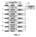
- FIG. 4 is a block diagram of a pipeline processor architecture 400 that is operable to process two or more processor threads Tl, T2, ... Tn. Instructions associated with processor threads T1, T2, ... Tn can be retrieved from, for example, an instruction cache (e.g., instruction cache 402).
- instruction cache e.g., instruction cache 402
- pipeline processor architecture 400 includes six pipeline stages.
- the six pipeline stages include an instruction fetch stage (IF), an instruction decode stage (ID), an instruction issue stage (IS), an instruction execution stage (EX), a data memory read stage (MEM), and write back stage (WB).
- Pipeline processor architecture 400 can include a different number of pipeline stages.
- Pipeline processor architecture 400 further includes an instruction fetch unit (IFU) 404, decode logic 406, issue logic 408, an execution unit 410, read logic 412, write logic 414, and a programmable thread allocation controller 416.
- IFU instruction fetch unit
- pipeline processor architecture 400 further includes a set registers (e.g., registers A1-A7, B1-B7, N1-N7) located between each pipeline stage (one before and after each stagé) for storing a state of a corresponding processor thread T1, T2, ... Tn during a context switch.
- set registers e.g., registers A1-A7, B1-B7, N1-N7 located between each pipeline stage (one before and after each stagé) for storing a state of a corresponding processor thread T1, T2, ... Tn during a context switch.
- Registers A1-A7 store a state of processor thread T1.
- registers B1-B7 store a state of processor thread T2
- registers N1-N7 store a state of processor thread Tn.
- each register A1-A7, B1-B7, N1-N7 stores a state of a corresponding processor thread including storing a state of data produced by a corresponding pipeline stage of pipeline processor architecture 400 at the end of given instruction cycle.
- register A3 can store a state of data for processor thread T1 received from decode logic 406, and register A5 can store a state of data received from execution unit 410.
- Registers A1-A7, B1-B7, N1-N7 facilitate context switches in that they permit a state of a corresponding processor thread to be directly loaded from (or stored to) a given register.
- each set of registers A1-A7, B1-B7, N1-N7 is located relatively close to a functional unit within pipeline processor architecture 400 (e.g., between each pipeline stage) and permits fast context switching times.
- programmable thread allocation controller 416 performs a context switch automatically by switching one or more multiplexers and/or de-multiplexers (not shown) located before or after each pipeline stage (e.g., pipeline stages IF, ID, IS, EX, MEM, WB).
- pipeline stage e.g., pipeline stages IF, ID, IS, EX, MEM, WB.
- processor thread T1 e.g., processor thread T1
- a state of a next processor thread (e.g., processor thread T2) is loaded from a different set of registers (e.g., registers B1-B7) associated with the next processor thread.
- the pipeline processor processes the next processor thread in the following instruction cycle.
- context switches occur at the end of an instruction cycle (i.e., after data from a pipeline stage has been saved to an associated register) to permit seamless context switches.
- FIG. 5 illustrates a block diagram of a pipeline processor 500 built in accordance with pipeline processor architecture 400 that processes two threads T1, T2.
- pipeline processor 500 includes an instruction fetch unit 504, a decoder 506, a register file 508, issue logic 510, a two-stage execution unit 512, a re-order buffer 514, and a programmable thread allocation controller 516.
- Pipeline processor 500 further includes a first set of registers A1-A6 that corresponds to processor thread T1, and a second set of registers B1-B6 that corresponds to processor thread T2.
- Pipeline processor 500 further includes program counters T1, T2, multiplexers 550, and de-multiplexers 552.
- instruction fetch unit 504 retrieves an instruction to be executed from, for example, instruction cache 502. Instruction fetch unit 504 retrieves instructions in accordance with program counters T1, T2.
- program counter T1 indicates an execution status of processor thread T1 (i.e., where pipeline processor 500 is with respect to an instruction sequence associated with processor thread T1)
- program counter T2 indicates an execution status associated with processor thread T2.
- instruction decode stage instructions retrieved by instruction fetch unit 504 are decoded.
- re-order buffer 514 stores the decoded instructions until the decoded instructions are issued for execution.
- re-order buffer 514 is a circular buffer.
- Re-order buffer 514 also stores the results of executed instructions until the executed instructions are ready for retirement, e.g., into register file 508.
- register file 508 includes two banks T1, T2.
- Bank T1 holds data associated with processor thread T1
- bank T2 holds data associated with processor thread T2.
- Register file 508 can include a thread index (not shown) that indicates registers from which data will be loaded. The thread index ensures that data from a register associated with a currently executing processor thread will be loaded into register file 508.
- execution unit 512 executes the decoded instructions issued from issue logic 510.
- Execution unit 512 can be any type of execution unit, as discussed above. Though execution unit 512 is shown as having two pipeline stages, execution unit 512 can have a different number of pipeline stages. In one implementation, results of the executed instructions are written back to re-order buffer 514, and then retired to register file 508.
- Programmable thread allocation controller 516 is operable to be programmed to store processor time allocation for each processor thread T1, T2.
- programmable thread allocation controller 516 automatically performs a context switch between processor threads T1, T2 by switching multiplexers 550 and de-multiplexers 552 located respectively before and after each pipeline stage (e.g., pipeline stages IF, ID, IS, EX1, EX2) of pipeline processor 500.
- pipeline stage e.g., pipeline stages IF, ID, IS, EX1, EX2
- pipeline stage e.g., pipeline stages IF, ID, IS, EX1, EX2
- State information for processor thread T2 is stored in registers B1-B6.
- registers A1-A6 store a state of processor thread T1
- a state of processor thread T2 is loaded from registers B1-B6 (through multiplexers 550 and de-multiplexers 552) and processed by pipeline processor 500.
- each of multiplexers 550 is a 2-to-1 multiplexer
- each of de-multiplexers 552 is a 1-to-2 de-multiplexer.
- An exception is an event that causes suspension of normal program execution.
- Types of exceptions include, for example, addressing exceptions, data exceptions, operation exceptions, overflow exceptions, protection exceptions, underflow exceptions, and so on.
- An exception may be generated by hardware or software.
- FIG. 6 illustrates a method for performing exception handling in a processor implemented according to pipeline processor architectures 100, 400.
- An exception request occurs while instruction i of a given thread is being executed (step 602).
- Program counter values associated with each processor thread are saved, along with a state of current instructions within the pipeline of the processor (step 604).
- all instructions within the pipeline of the processor are aborted, or flushed.
- the processor jumps to an exception handling routine associated with a given thread (step 606).
- each processor thread has an associated exception handling routine that is separate and independent from exception handling routines associated with other processor threads.
- a single exception handling routine performs exception requests for substantially all processor threads.
- the exception request is executed by a given exception handling routine (step 608).
- program counter values are restored within program counters of the processor, and a state of instructions (prior to the exception request) is restored within the pipeline of the processor (step 610).
- the processor resumes program execution of the next instruction (e.g., instruction i +1) after returning from an exception handling routine (step 612).
- the processor can resume program instruction at instruction i if the instruction is to be re-executed.
- FIG. 7 illustrates a method for handling interrupts in a processor implemented according to pipeline processor architectures 100, 400.
- An interrupt occurs while instruction i of a given thread is being executed (step 702).
- Program counter values associated with each processor thread are saved, along with a state of current instructions within the pipeline of the processor (step 704).
- the processor jumps to an interrupt handling routine associated with a given thread (step 706).
- each processor thread has an associated interrupt handling routine having an entry point that is separate and independent from entry points associated with interrupt handling routines associated with other processor threads.
- An entry point is a starting address of an interrupt handling routine.
- a single interrupt handling routine (with a single entry point) performs interrupts for substantially all processor threads.
- the interrupt is executed by a given interrupt handling routine (step 708). After the interrupt has been performed by the processor, program counter values are restored within program counters of the processor, and a state of instructions (prior to the interrupt request) is restored within the pipeline of the processor (step 710). The processor resumes program execution of the next instruction (e.g., instruction i+1) after returning from an interrupt handling routine (step 712).
- a pipeline processor built in accordance with pipeline processor architectures 100, 400 can be used in a wide range of applications.
- Example applications include data storage applications, wireless applications, and computer system applications.
Landscapes
- Engineering & Computer Science (AREA)
- Software Systems (AREA)
- Theoretical Computer Science (AREA)
- Physics & Mathematics (AREA)
- General Engineering & Computer Science (AREA)
- General Physics & Mathematics (AREA)
- Multimedia (AREA)
- Advance Control (AREA)
Abstract
Description
- The following disclosure relates to processing circuits and systems.
- Conventional operating systems typically support multitasking, which is a scheduling scheme that permits more than one processor thread to share common processing resources. A processor thread represents an architectural state within a processor that tracks execution of a software program. In the case of a computer having a single processor, only one processor thread is processed at any given point in time, meaning that the processor is actively executing instructions associated with a single processor thread. The act of re-assigning a processor from one processor thread to another is called a context switch.
- In a conventional pipeline processor, a context switch typically occurs through a hardware interrupt and interrupt service routine. Interrupt service routines typically have an associated execution time, or interrupt overhead, that may consume valuable processor time. Additionally, in a conventional pipeline processor, a context switch typically occurs only at fixed intervals (e.g., every 100 µs), as determined by, e.g., vendors of an operating system.
- In general, in one aspect, this specification describes a processor including a pipeline stage. The pipeline stage includes a first input register, a second input register, a first output register, and a second output register. The processor further includes a first selector in communication with the first input register and the second input register, and a second selector in communication with the first output register and the second output register. The processor also includes a controller operable to control switching of the first and second selectors such that data associated with a first processor thread passes through the first input register, the pipeline stage, and the first output register during a time that the first processor thread is being processed, and data associated with a second processor thread passes through the second input register, the pipeline stage, and the second output register during a time that the second processor thread is being processed. The first input register and the first output register are operable to store a state of the first processor thread, and the second input register and the second output register are operable to store a state of the second processor thread.
- Particular implementations can include one or more of the following features. The first selector can include a multiplexer and the second selector can include a de-multiplexer. The pipeline stage can include one of an instruction fetch unit, decode logic, issue logic, execution unit, read logic, or write logic. The controller can control switching of the first and second selectors based on input defining processor time to be allocated to each of the first and the second processor threads. The controller can control switching of the first and second selectors dynamically during execution of a program or statically based on a previously established processor time allocation for each of the first and second processor threads.
- The processor can further include a first interrupt handling routine to handle an interrupt request associated with the first processor thread, and a second interrupt handling routine to handle an interrupt request associated with the second processor thread. The first interrupt handling routine and the second interrupt handling routine can have separate entry points. The processor can further include a first exception handling routine to handle an exception request associated with the first processor thread, and a second exception handling routine to handle an exception request associated with the second processor thread. The processor can further include a single exception handling routine or a single interrupt handling routine to respectively handle substantially all exception requests or substantially all interrupt requests associated with both the first and second processor threads.
- The processor can further include a set of registers corresponding to each of a plurality of processor threads. Each register within a set can be located either before or after a pipeline stage of the processor. The controller can perform a context switch among the plurality of processor threads, including storing a state of a currently executing processor thread in a corresponding set of registers, and loading a state of another processor thread from a corresponding set of registers to allow for processing of the another processor thread.
- In general, in another aspect, this specification describes a processor including a set of registers corresponding to each of a plurality of processor threads. Each register within a set is located either before or after a pipeline stage of the processor. The processor further includes a programmable controller operable to perform a context switch among the plurality of processor threads, including storing a state of a currently executing processor thread in a corresponding set of registers, and loading a state of another processor thread from a corresponding set of registers to allow for processing of the another processor thread.
- Particular implementations can include one or more of the following features. The programmable controller can perform the context switch at an end of an instruction cycle. The processor can further include a register file having a plurality of banks corresponding to each of the plurality of processor threads. Each bank can store data associated with a corresponding processor thread. The processor can further include a plurality of program counters, each program counter operable to indicate an execution status of a corresponding processor thread. The processor can further include a plurality of interrupt handling routines corresponding to the plurality of processor threads, in which each interrupt handling routine handles an interrupt request associated with a corresponding processor thread. Each of the plurality of interrupt handling routines can have separate entry points. The processor can further include a plurality of exception handling routines corresponding to the plurality of processor threads, in which each exception handling routine handles an exception request associated with a corresponding processor thread. The processor can include a single exception handling routine or a single interrupt handling routine to respectively handle substantially all exception requests or substantially all interrupt requests associated with the plurality of processor threads.
- In general, in another aspect, this specification describes a method including providing a first processor thread for instruction execution; providing a second processor thread for instruction execution; processing the first processor thread; and performing a context switch from the first processor thread to the second processor thread. Performing a context switch includes storing a state of the first processor thread in a first set of registers corresponding to the first processor thread, and loading a state of the second processor thread from a second set of registers corresponding to the second processor thread.
- Particular implementations can include one or more of the following features. Storing a state of a given processor thread within a corresponding set of registers can include storing data corresponding to a pipeline stage of a processor. The method can further include receiving input changing the processor time allocation, and performing a context switch among the first and second processor threads based on the changed processor time allocation. Performing a context switch can include performing a context switch dynamically during execution of a program or statically based on a previously established processor time allocation for each of the first and second processor threads. The method can further include using a first interrupt handling routine to handle an interrupt request associated with the first processor thread, and using a second interrupt handling routine to handle an interrupt request associated with the second processor thread. The method can further include using a first exception handling routine to handle an exception request associated with the first processor thread, and using a second exception handling routine to handle an exception request associated with the second processor thread. The method can further include using a single exception handling routine or a single interrupt handling routine to respectively handle substantially all exception requests and substantially all interrupt requests associated with the first and second processor threads.
- In general, in another aspect, this specification describes a processor including an instruction fetch unit operable to fetch instructions associated with a plurality of processor threads, a decoder responsive to the instruction fetch unit, issue logic responsive to the decoder, and a register file including a plurality of banks corresponding to the plurality of processor threads. Each bank is operable to only store data associated with a corresponding processor thread.
- Particular implementations can include one or more of the following features. The data can include operands or results of executed instructions associated with a given processor thread. The processor can further include a controller in communication with the instruction fetch unit. The controller can determine a processor thread from which a next instruction will be fetched by the instruction fetch unit. The processor can further include a set of registers corresponding to each of the plurality of threads. Each register within a set can be located either before or after a pipeline stage of the processor. The controller can perform a context switch among the plurality of processor threads, including storing a state of a currently executing processor thread in a corresponding set of registers, and loading a state of another processor thread from a corresponding set of registers to allow for processing of the another processor thread. The controller can include a plurality of thread allocation counters corresponding to the plurality of processor threads. Each thread allocation counter can contain a value representing how much processor time is to be allocated for a respective processor thread. The controller can perform a context switch including switching a selector that is in communication with the instruction fetch unit. The selector can include a multiplexer or a de-multiplexer.
- In general, in one aspect, this specification describes a processor including means for executing instructions through a pipeline stage. The means for executing instructions includes a first input means for storing data, a second input means for storing data, a first output means for storing data, and a second output means for storing data. The processor further includes a first means for selecting in communication with the first input means for storing data and the second input means for storing data, and a second means for selecting in communication with the first output means for storing data and the second output means for storing data. The processor also includes means for controlling switching of the first and second means for selecting such that data associated with a first processor thread passes through the first input means for storing data, the means for executing, and the first output means for storing data during a time that the first processor thread is being processed, and data associated with a second processor thread passes through the second input means for storing data, the means for executing, and the second output means for storing data during a time that the second processor thread is being processed. The first input means for storing data and the first output means for storing data are operable to store a state of the first processor thread, and the second input means for storing data and the second output means for storing data are operable to store a state of the second processor thread.
- In general, in another aspect, this specification describes a processor including means for storing data corresponding to each of a plurality of processor threads. Each means for storing data is located either before or after a stage means of the processor. The processor further includes means for performing a context switch among the plurality of processor threads, including means for storing a state of a currently executing processor thread in a corresponding set of means for storing data, and loading a state of another processor thread from a corresponding set of means for storing data to allow for processing of the another processor thread.
- In general, in another aspect, this specification describes a processor including means for fetching instructions associated with a plurality of processor threads, means for decoding the fetched instructions, means for issuing decoded instructions, and means for storing data associated with a corresponding processor thread within a corresponding means for storing.
- Particular implementations can include one or more of the following features. The data can include operands or results of executed instructions associated with a given processor thread. The processor can further include means for determining a processor thread from which a next instruction will be fetched. The processor can further include means for storing data corresponding to each of the plurality of processor threads. Each means for storing data can be located either before or after a stage means of the processor. The processor can include means for performing a context switch among the plurality of processor threads, including means for storing a state of a currently executing processor thread in a corresponding means for storing data, and loading a state of another processor thread from a corresponding means for storing data to allow for processing of the another processor thread.
- The means for performing a context switch can include means for storing a value representing how much processor time is to be allocated for a respective processor thread. The means for performing a context switch can include means for switching a selector that is in communication with the means for fetching.
- Implementations can include one or more of the following advantages. A pipeline processor is provided that performs context switches without any interrupt overhead associated with hardware interrupts - e.g., an interrupt service routine. In one implementation, context switches occur automatically, and primarily through hardware, e.g., using a programmable thread allocation controller. In one implementation, a pipeline processor saves a state of a first processor thread to a first set of registers located between each pipeline stage of the pipeline processor, and loads a state of a second processor thread from a second set of registers also located between each pipeline stage of the pipeline processor. The location of the registers allow for fast context switching times.
- Users, e.g., network administrators can customize how much processor time is allocated to each processor thread. In one implementation, after an initial processor time allocation has been established, users can further dynamically change the processor time allocation. Users can retain full control of processor time allotment rather than relinquishing the control to an operating system.
- The details of one or more implementations are set forth in the accompanying drawings and the description below. Other features and advantages will be apparent from the description and drawings, and from the claims.
- FIG. 1 is a block diagram of a pipeline processor architecture.
- FIG. 2 is method of operation in the pipeline processor architecture of FIG. 1.
- FIG. 3 is a block diagram of a pipeline processor in accordance with the pipeline processor architecture of FIG. 1.
- FIG. 4 is a block diagram of a pipeline processor architecture.
- FIG. 5 is a block diagram of a pipeline processor in accordance with the pipeline processor architecture of FIG. 4.
- FIG. 6 is a method of performing exception handling in the pipeline processor architectures of FIGS. 1 and 4.
- FIG. 7 is a method of performing interrupt handling in the pipeline processor architectures of FIGS. 1 and 4.
- Like reference symbols in the various drawings indicate like elements.
- FIG. 1 is a block diagram of a
pipeline processor architecture 100 that is operable to process two or more processor threads T1, T2, ... Tn. Processor threads T1, T2, ... Tn each represent an architectural state withinpipeline processor architecture 100 that tracks execution of corresponding software programs. Instructions for the software programs can be retrieved from, for example, an instruction cache (e.g., instruction cache 102). In one implementation,pipeline processor architecture 100 includes two or more program counters (not shown) each of which corresponds to a processor thread T1, T2, ... Tn. Each program counter indicates where (for a corresponding processor thread T1, T2, ... Tn)pipeline processor architecture 100 is with respect to an instruction sequence. Program counters are discussed in greater detail below in association with FIGS. 3 and 5. - In one implementation,
pipeline processor architecture 100 includes six pipeline stages. The six pipeline stages include an instruction fetch stage (IF), an instruction decode stage (ID), an instruction issue stage (IS), an instruction execution stage (EX), a data memory read stage (MEM), and write back stage (WB).Pipeline processor architecture 100, however, can include a different number of pipeline stages.Pipeline processor architecture 100 further includes an instruction fetch unit (IFU) 104, decode logic 106,issue logic 108, aregister file 110, anexecution unit 112, readlogic 114, write logic 116, and a programmablethread allocation controller 118. - Instruction fetch
unit 104 retrieves program instructions from, e.g.,instruction cache 102. Decode logic 106 decodes the program instructions and generates decoded instructions to be executed byexecution unit 112. In one implementation, the decoded instructions are fixed length micro-op instructions.Issue logic 108 issues decoded instructions toexecution unit 112 for execution.Execution unit 112 can be a load execution unit, store execution unit, arithmetic logic unit (ALU), multiply and accumulate (MAC) unit, or a composite load/store execution unit as described in U.S. patent application entitled -- "Variable Length Pipeline Processor Architecture" by Hong-yi Chen and Jensen Tjeng, attorney docket no. MP0634/13361-140001, which is incorporated by reference in its entirety. Readlogic 114 reads data from, e.g., a data cache (not shown). Write logic 116 writes results of executed instructions back to, e.g., a data cache,register file 110, or a re-order buffer (not shown). -
Register file 110 stores data associated with each processor thread T1, T2, ... Tn. In one implementation,register file 110 includes separate banks (e.g., banks T1, T2, ... Tn) that store data associated with a corresponding processor thread T1, T2, ... Tn. For example, if write logic 116 is writing data associated with processor thread T2 back to registerfile 110, then write logic 116 writes the data to bank T2 ofregister file 110. Alternatively, a separate register file (not shown) for storing data corresponding to each processor thread T1, T2, ... Tn can be implemented withinpipeline processor architecture 100. - Programmable
thread allocation controller 118 can be programmed to store processor time allocations that have been defined for each processor thread T1, T2, ... Tn - i.e., what portion of processor time will be dedicated to each processor thread T1, T2, ... Tn. In one implementation, input , e.g., from a user, defining portions of processor time to be allocated to each of a plurality of processor threads (e.g., processor threads T1, T2, ... Tn) is received through a graphical user interface (not shown). For example, a user can allocate 95% of processor time to a first processor thread and 5% to a second processor thread for a dual thread pipeline processor. In one implementation, the processor time allocation defined for each processor thread (e.g., processor threads T1, T2, ... Tn) can be dynamically changed - i.e., changed during program execution - by a user or preferably by a software program (e.g., a software program to be executed). Alternatively, the processor time allocation for each processor thread can be statically set - i.e., not changeable during program execution. - In one implementation, programmable
thread allocation controller 118 performs a context switch automatically by determining a processor thread from which a next instruction will be fetched (e.g., by instruction fetch unit 104). In one implementation, programmablethread allocation controller 118 performs a context switch by switching one or more selectors ,e.g., multiplexers and/or de-multiplexers (not shown) that are in communication with instruction fetchunit 104. One implementation of a processor including multiplexers and de-multiplexers that performs context switches is discussed below in association with FIGS. 3, 4, and 5. When a context switch occurs, an instruction associated with a next processor thread is fetched by instruction fetchunit 104. Though the pipeline stages (e.g., pipeline stages IF, ID, IS, EX, MEM, WB) ofpipeline processor architecture 100 may contain instructions associated with two or more processor threads, data associated with each given processor thread is maintained separately throughregister file 110, thus, the integrity of data associated with each processor thread is maintained. Unlike a conventional pipeline processor that may require an interrupt service routine, programmablethread allocation controller 118 does not have any interrupt overhead associated with performing a context switch. - FIG. 2 shows a
method 200 for processing processor threads through a pipeline processor architecture (e.g., pipeline processor architecture 100). Input defining a portion of processor time to be allocated to each of a plurality of processor threads is received (step 202). In one implementation, input allocations are received from a user through a graphical user interface. The processor time allocated to each processor thread can be stored in a programmable thread allocation controller (e.g., programmable thread allocation controller 118). In one implementation, processor time is allocated based on CPU (Central Processing Unit) cycles, clock cycles and/or instruction cycles. - Each thread is processed by the pipeline processor according to the processor time allocated to each thread (step 204). In one implementation, a context switch occurs automatically according to the processor time allocated to each thread as stored in the programmable thread allocation controller. In one implementation, a programmable thread allocation controller controls switching of one or more multiplexers and/or de-multiplexers that are in communication with an instruction fetch unit (e.g., instruction fetch unit 104). In one implementation, a programmable thread allocation controller controls switching of one or more multiplexers and/or de-multiplexers located before and after each pipeline stage of the pipeline processor to perform a context switch, as discussed in greater detail below. In this implementation, a state of a processor thread is stored in, and loaded from, registers that are located before and after each pipeline stage in the pipeline processor. In one implementation, context switches occur at the end of a given instruction cycle.
- A determination is made (e.g., through programmable thread allocation controller 118) whether input dynamically changing the processor time allocation is received (step 206). If the processor time allocated to each processor thread has not been dynamically changed, then each processor thread is processed according to the processor time allocation as previously established, and
method 200 returns to step 204. If the processor time allocation has been dynamically changed, then each processor thread is processed according to the changed processor time allocation (step 208). Afterstep 208,method 200 returns to step 206, discussed above. - FIG. 3 illustrates a block diagram of a
pipeline processor 300 built in accordance withpipeline processor architecture 100 that processes (n) processor threads T1, T2, ... Tn. In one implementation,pipeline processor 300 includes an instruction fetchunit 304, adecoder 306, a register file 308,issue logic 310, a two-stage execution unit 312, are-order buffer 314, and a programmablethread allocation controller 316.Pipeline processor 300 further includes registers T1-Tn and program counters T1-Tn that respectively correspond to processor threads T1, T2, ... Tn.Pipeline processor 300 further includesmultiplexer 350. - In one implementation, during an instruction fetch (IF) stage, instruction fetch
unit 304 retrieves an instruction to be executed from, for example,instruction cache 302. Instruction fetchunit 304 retrieves instructions in accordance with program counters T1, T2, ... Tn. In one implementation, program counter T1 indicates an execution status of processor thread T1 (i.e., wherepipeline processor 300 is with respect to an instruction sequence associated with processor thread Tl), program counter T2 indicates an execution status associated with processor thread T2, and program counter Tn indicates an execution status associated with processor thread Tn. - During an instruction decode stage (ID), instructions retrieved by instruction fetch
unit 304 are decoded. - During an instruction issue stage (IS), in one implementation, the decoded instructions are sent to re-order buffer 314 (through issue logic 310).
Re-order buffer 314 stores the decoded instructions until the decoded instructions are issued for execution. In one implementation,re-order buffer 314 is a circular buffer. -
Re-order buffer 314 also stores the results of executed instructions until the executed instructions are ready for retirement, e.g., into register file 308. In one implementation, register file 308 includes banks (e.g., banks T1, T2, ... Tn) that correspond to each processor thread (e.g., processor threads T1, T2, ... Tn) processed byprocessor 300. Bank T1 holds data associated with processor thread T1, bank T2 holds data associated with processor thread T2, and bank Tn holds data associated with processor thread Tn. The data can include operands and/or results of executed instructions associated with a given processor thread. In one implementation,pipeline processor 300 does not include are-order buffer 314. - During executions stages EX1, EX2,
execution unit 312 executes the decoded instructions issued fromissue logic 310.Execution unit 312 can be any type of execution unit, as discussed above. Thoughexecution unit 312 is shown as having two pipeline stages,execution unit 312 can have a different number of pipeline stages. In one implementation, results of the executed instructions are written back to re-orderbuffer 314, and then retired to register file 308. - Programmable
thread allocation controller 316 is operable to be programmed to store processor time allocation for each processor thread T1, T2, ... Tn - i.e., how much processor time will be dedicated to each processor thread T1, T2, ... Tn. In one implementation, input, e.g., from a user, allocating portions of processor time to each processor thread T1, T2, ... Tn is received through a graphical user interface (not shown). In one implementation, the processor time allocation for each processor thread T1, T2, ... Tn can be dynamically changed by a user. In one implementation, the processor time allocation for each processor thread T1, T2, ... Tn is changed dynamically through a software application being processed byprocessor 300. - In one implementation, programmable
thread allocation controller 316 automatically performs a context switch between processor threads T1, T2, ... Tn by switchingmultiplexer 350 that is in communication with instruction fetchunit 304. For example, during a time thatpipeline processor 300 is processing processor thread T1,multiplexer 350 is controlled to pass instructions associated with processor thread T1 through the pipeline stages ofpipeline processor 300. When a context switch occurs from processor thread T1,multiplexer 350 is controlled to pass instructions associated with another processor thread, e.g., processor thread T2. In one implementation,multiplexer 350 is an n-to-1 multiplexer. - In one implementation, programmable
thread allocation controller 316 includes a plurality of thread allocation counters (e.g., thread allocation counters T1-Tn) that determine a weighting that corresponds to processor time allocated to each processor thread. For example, in one implementation, each of thread allocation counters Ti-Tn contains a value that represents how many CPU cycles are allocated for each thread. For example, if thread allocation counter T1 contains a value of 256, thread allocation counter T2 contains a value of 16, and thread allocation counter Tn contains a zero value, then instructions will be first fetched from processor thread T1 for 256 CPU cycles, then instructions will be fetched from processor thread T2 for 16 CPU cycles, and zero instructions will be fetched from processor thread Tn. Instructions are then fetched from processor threads T1 and T2 again for another 256 CPU cycles and 16 CPU cycles, respectively, and so on. The instruction fetching can continue accordingly until the values within one or more of the thread allocation counters are changed. As each thread allocation counter Tl-Tn reaches a zero value, then programmablethread allocation counter 316 switches multiplexer 350 to pass instructions associated with a next processor thread to instruction fetchunit 304 for processing. - FIG. 4 is a block diagram of a
pipeline processor architecture 400 that is operable to process two or more processor threads Tl, T2, ... Tn. Instructions associated with processor threads T1, T2, ... Tn can be retrieved from, for example, an instruction cache (e.g., instruction cache 402). - In one implementation,
pipeline processor architecture 400 includes six pipeline stages. The six pipeline stages include an instruction fetch stage (IF), an instruction decode stage (ID), an instruction issue stage (IS), an instruction execution stage (EX), a data memory read stage (MEM), and write back stage (WB).Pipeline processor architecture 400, however, can include a different number of pipeline stages.Pipeline processor architecture 400 further includes an instruction fetch unit (IFU) 404, decode logic 406,issue logic 408, anexecution unit 410, readlogic 412, writelogic 414, and a programmable thread allocation controller 416.Pipeline processor architecture 400 is similar to pipeline processor architecture of FIG. 1, however,pipeline processor architecture 400 further includes a set registers (e.g., registers A1-A7, B1-B7, N1-N7) located between each pipeline stage (one before and after each stagé) for storing a state of a corresponding processor thread T1, T2, ... Tn during a context switch. - Registers A1-A7 store a state of processor thread T1. In a like manner, registers B1-B7 store a state of processor thread T2, and registers N1-N7 store a state of processor thread Tn. In one implementation, each register A1-A7, B1-B7, N1-N7 stores a state of a corresponding processor thread including storing a state of data produced by a corresponding pipeline stage of
pipeline processor architecture 400 at the end of given instruction cycle. For example, when processing instructions associated with processor thread T1, at the end of an instruction cycle register A3 can store a state of data for processor thread T1 received from decode logic 406, and register A5 can store a state of data received fromexecution unit 410. Registers A1-A7, B1-B7, N1-N7 facilitate context switches in that they permit a state of a corresponding processor thread to be directly loaded from (or stored to) a given register. In one implementation, each set of registers A1-A7, B1-B7, N1-N7 is located relatively close to a functional unit within pipeline processor architecture 400 (e.g., between each pipeline stage) and permits fast context switching times. - In one implementation, programmable thread allocation controller 416 performs a context switch automatically by switching one or more multiplexers and/or de-multiplexers (not shown) located before or after each pipeline stage (e.g., pipeline stages IF, ID, IS, EX, MEM, WB). One implementation of a processor including multiplexers and de-multiplexers that performs context switches is discussed below in association with FIG. 5. When a context switch occurs, one set of registers (e.g., registers A1-A7) associated with a current processor thread (e.g., processor thread T1) from which the context switch is to occur stores a state of the current processor thread. To complete the context switch, a state of a next processor thread (e.g., processor thread T2) is loaded from a different set of registers (e.g., registers B1-B7) associated with the next processor thread. The pipeline processor processes the next processor thread in the following instruction cycle. In one implementation, context switches occur at the end of an instruction cycle (i.e., after data from a pipeline stage has been saved to an associated register) to permit seamless context switches.
- FIG. 5 illustrates a block diagram of a
pipeline processor 500 built in accordance withpipeline processor architecture 400 that processes two threads T1, T2. In one implementation,pipeline processor 500 includes an instruction fetchunit 504, a decoder 506, aregister file 508,issue logic 510, a two-stage execution unit 512, are-order buffer 514, and a programmable thread allocation controller 516.Pipeline processor 500 further includes a first set of registers A1-A6 that corresponds to processor thread T1, and a second set of registers B1-B6 that corresponds to processor thread T2.Pipeline processor 500 further includes program counters T1, T2,multiplexers 550, and de-multiplexers 552. - In one implementation, during an instruction fetch (IF) stage, instruction fetch
unit 504 retrieves an instruction to be executed from, for example,instruction cache 502. Instruction fetchunit 504 retrieves instructions in accordance with program counters T1, T2. In one implementation, program counter T1 indicates an execution status of processor thread T1 (i.e., wherepipeline processor 500 is with respect to an instruction sequence associated with processor thread T1), and program counter T2 indicates an execution status associated with processor thread T2. - During an instruction decode stage (ID), instructions retrieved by instruction fetch
unit 504 are decoded. - During an instruction issue stage (IS), in one implementation, the decoded instructions are sent to re-order buffer 514 (through issue logic 510).
Re-order buffer 514 stores the decoded instructions until the decoded instructions are issued for execution. In one implementation,re-order buffer 514 is a circular buffer. -
Re-order buffer 514 also stores the results of executed instructions until the executed instructions are ready for retirement, e.g., intoregister file 508. In one implementation,register file 508 includes two banks T1, T2. Bank T1 holds data associated with processor thread T1, and bank T2 holds data associated with processor thread T2.Register file 508 can include a thread index (not shown) that indicates registers from which data will be loaded. The thread index ensures that data from a register associated with a currently executing processor thread will be loaded intoregister file 508. - During executions stages EX1, EX2,
execution unit 512 executes the decoded instructions issued fromissue logic 510.Execution unit 512 can be any type of execution unit, as discussed above. Thoughexecution unit 512 is shown as having two pipeline stages,execution unit 512 can have a different number of pipeline stages. In one implementation, results of the executed instructions are written back to re-orderbuffer 514, and then retired to registerfile 508. - Programmable thread allocation controller 516 is operable to be programmed to store processor time allocation for each processor thread T1, T2. In one implementation, programmable thread allocation controller 516 automatically performs a context switch between processor threads T1, T2 by switching
multiplexers 550 andde-multiplexers 552 located respectively before and after each pipeline stage (e.g., pipeline stages IF, ID, IS, EX1, EX2) ofpipeline processor 500. For example, during a time thatpipeline processor 500 is processing processor thread T1,multiplexers 550 andde-multiplexers 552 are controlled to pass instructions associated with processor thread T1 (through the pipeline stages of pipeline processor 500). State information for processor thread T2 is stored in registers B1-B6. When a context switch occurs from processor thread T1, registers A1-A6 store a state of processor thread T1, and a state of processor thread T2 is loaded from registers B1-B6 (throughmultiplexers 550 and de-multiplexers 552) and processed bypipeline processor 500. In one implementation, each ofmultiplexers 550 is a 2-to-1 multiplexer, and each ofde-multiplexers 552 is a 1-to-2 de-multiplexer. - When a processor (e.g.,
processors 300, 500) built in accordance withpipeline processor architectures - FIG. 6 illustrates a method for performing exception handling in a processor implemented according to
pipeline processor architectures - The exception request is executed by a given exception handling routine (step 608). After the exception request has been performed by the processor, program counter values are restored within program counters of the processor, and a state of instructions (prior to the exception request) is restored within the pipeline of the processor (step 610). The processor resumes program execution of the next instruction (e.g., instruction i+1) after returning from an exception handling routine (step 612). In
step 612, the processor can resume program instruction at instruction i if the instruction is to be re-executed. - Interrupts within a processor implemented according to
pipeline processor architectures pipeline processor architectures - An interrupt occurs while instruction i of a given thread is being executed (step 702). Program counter values associated with each processor thread are saved, along with a state of current instructions within the pipeline of the processor (step 704). The processor jumps to an interrupt handling routine associated with a given thread (step 706). In one implementation, each processor thread has an associated interrupt handling routine having an entry point that is separate and independent from entry points associated with interrupt handling routines associated with other processor threads. An entry point is a starting address of an interrupt handling routine. In one implementation, a single interrupt handling routine (with a single entry point) performs interrupts for substantially all processor threads.
- The interrupt is executed by a given interrupt handling routine (step 708). After the interrupt has been performed by the processor, program counter values are restored within program counters of the processor, and a state of instructions (prior to the interrupt request) is restored within the pipeline of the processor (step 710). The processor resumes program execution of the next instruction (e.g., instruction i+1) after returning from an interrupt handling routine (step 712).
- A pipeline processor built in accordance with
pipeline processor architectures - A number of implementations have been described. Nevertheless, it will be understood that various modifications may be made without departing from the spirit and scope of the invention. For example, the steps of the methods described above can be performed in a different order and still achieve desirable results. Accordingly, other implementations are within the scope of the following claims.
Claims (27)
- A processor, comprising:a pipeline stage including,a first input register;a second input register;a first output register;a second output register;a first selector in communication with the first input register and the second input register;a second selector in communication with the firstoutput register and the second output register; anda controller operable to control switching of thefirst and second selectors such that data associated with a first processor thread pass through the first input register, the pipeline stage, and the first output register during a time that the first processor thread is being processed, and data associated with a second processor thread pass through the second input register, the pipeline stage, and the second output register during a time that the second processor thread is being processed,wherein the first input register and the first output register are operable to store a state of the first processor thread, and wherein the second input register and the second output register are operable to store a state of the second processor thread.
- The processor of claim 1, wherein the controller controls switching of the first and second selectors based on input defining processor time to be allocated to each of the first processor thread and the second processor thread.
- The processor of claim 1, further comprising:a first interrupt handling routine to handle an interrupt request associated with the first processor thread; anda second interrupt handling routine to handle an interrupt request associated with the second processor thread.
- The processor of claim 3, wherein the first interrupt handling routine and the second interrupt handling routine have separate entry points.
- The processor of claim 1, further comprising:a first exception handling routine to handle an exception request associated with the first processor thread; anda second exception handling routine to handle an exception request associated with the second processor thread.
- The processor of claim 1, further comprising a single exception handling routine or a single interrupt handling routine to respectively handle substantially all exception requests or substantially all interrupt requests associated with both the first processor thread and the second processor thread.
- The processor of claim 1, further comprising:a set of registers corresponding to each of a plurality of processor threads, including the first processor thread and the second processor thread, each register within a set being located either before or after the pipeline stage of the processor; andwherein the controller comprises a programmable controller operable to perform a context switch among the plurality of processor threads, including storing a state of a currently executing processor thread in a corresponding set of registers, and loading a state of another processor thread from a corresponding set of registers to allow for processing of the another processor thread.
- The processor of claim 7, further comprising a register file including a plurality of banks corresponding to each of the plurality of processor threads, each bank operable to store data associated with a corresponding processor thread.
- The processor of claim 7, further comprising a plurality of program counters, each program counter operable to indicate an execution status of a corresponding processor thread.
- The processor of claim 1, further comprising:an instruction fetch unit operable to fetch instructions associated with a plurality of processor threads, including the first processor thread and the second processor thread;a decoder responsive to the instruction fetch unit;issue logic responsive to the decoder; anda register file including a plurality of banks corresponding to the plurality of processor threads, each bank operable to only store data associated with a corresponding processor thread.
- The processor of claim 10, wherein the data includes operands or results of executed instructions associated with a given processor thread.
- The processor of claim 10, the controller in communication with the instruction fetch unit, the controller operable to determine a processor thread from which a next instruction will be fetched by the instruction fetch unit.
- The processor of claim 10, further comprising:a set of registers corresponding to each of the plurality of processor threads, each register within a set being located either before or after a pipeline stage of the processor,whereinthe controller is operable to perform a context switch among the plurality of processor threads, including storing a state of a currently executing processor thread in a corresponding set of registers, and loading a state of another processor thread from a corresponding set of registers to allow for processing of the another processor thread.
- The processor of claim 10, wherein the controller includes a plurality of thread allocation counters corresponding to the plurality of processor threads, each thread allocation counter containing a value representing how much processor time is to be allocated for a respective processor thread.
- The processor of claim 10, wherein the controller is operable to perform a context switch including switching a selector that is in communication with the instruction fetch unit.
- The processor of claim 15, wherein the controller is operable to control switching of the selector that is in communication with the instruction fetch unit dynamically during execution of a program.
- The processor of claim 15, wherein the controller is operable to control switching of the selector that is in communication with the instruction fetch unit statically based on a pre-determined processor time allocation for each of the plurality of processor threads.
- A method comprising:providing a first processor thread for instruction execution;providing a second processor thread for instruction execution;processing the first processor thread; andperforming a context switch from the first processor thread to the second processor thread including,storing a state of the first processor thread in a first set of registers corresponding to the first processor thread; andloading a state of the second processor thread from a second set of registers corresponding to the second processor thread.
- The method of claim 18, wherein storing a state of a given processor thread within a corresponding set of registers includes storing data corresponding to a pipeline stage of a processor.
- The method of claim 18, further comprising:receiving input changing the processor time allocation; andperforming a context switch among the first and second processor threads based on the changed processor time allocation.
- The method of claim 18, wherein performing a context switch includes performing a context switch dynamically during execution of a program.
- The method of claim 18, wherein performing a context switch includes performing a context switch statically based on a pre-determined processor time allocation for each of the first processor thread and the second processor thread.
- The method of claim 18, wherein performing a context switch includes performing the context switch at an end of an instruction cycle.
- The method of claim 18, further comprising storing data associated with a given processor thread in a corresponding bank of a register file.
- The method of claim 18, further comprising indicating an execution status of a corresponding processor thread.
- The method of claim 18, further comprising:fetching instructions associated with a plurality of processor threads, including the first processor thread and the second processor thread;decoding the instructions;issuing the instructions to an execution unit; andstoring data associated with an issued instruction of a given processor thread within a corresponding bank of a register file, wherein each bank only stores data associated with a corresponding processor thread.
- The method of claim 26, further comprising determining a processor thread from which a next instruction will be fetched.
Applications Claiming Priority (1)
| Application Number | Priority Date | Filing Date | Title |
|---|---|---|---|
| US11/084,364 US8195922B2 (en) | 2005-03-18 | 2005-03-18 | System for dynamically allocating processing time to multiple threads |
Publications (2)
| Publication Number | Publication Date |
|---|---|
| EP1703377A2 true EP1703377A2 (en) | 2006-09-20 |
| EP1703377A3 EP1703377A3 (en) | 2007-11-28 |
Family
ID=36577509
Family Applications (1)
| Application Number | Title | Priority Date | Filing Date |
|---|---|---|---|
| EP20060005551 Withdrawn EP1703377A3 (en) | 2005-03-18 | 2006-03-17 | Multi-threaded processor |
Country Status (6)
| Country | Link |
|---|---|
| US (2) | US8195922B2 (en) |
| EP (1) | EP1703377A3 (en) |
| JP (2) | JP2006260571A (en) |
| CN (1) | CN100440139C (en) |
| SG (1) | SG126072A1 (en) |
| TW (1) | TWI315848B (en) |
Cited By (1)
| Publication number | Priority date | Publication date | Assignee | Title |
|---|---|---|---|---|
| CN103916915A (en) * | 2014-04-10 | 2014-07-09 | 泉州旭辉电子有限公司 | Method for designing analog-digital self-adaption switching wireless communication system |
Families Citing this family (80)
| Publication number | Priority date | Publication date | Assignee | Title |
|---|---|---|---|---|
| US8195922B2 (en) | 2005-03-18 | 2012-06-05 | Marvell World Trade, Ltd. | System for dynamically allocating processing time to multiple threads |
| US20060212853A1 (en) * | 2005-03-18 | 2006-09-21 | Marvell World Trade Ltd. | Real-time control apparatus having a multi-thread processor |
| CN103646009B (en) | 2006-04-12 | 2016-08-17 | 索夫特机械公司 | The apparatus and method that the instruction matrix of specifying parallel and dependent operations is processed |
| WO2008061154A2 (en) | 2006-11-14 | 2008-05-22 | Soft Machines, Inc. | Apparatus and method for processing instructions in a multi-threaded architecture using context switching |
| CN101325063B (en) * | 2007-06-12 | 2011-02-16 | 建兴电子科技股份有限公司 | Method for searching locating point position in holography storage system |
| US8725991B2 (en) * | 2007-09-12 | 2014-05-13 | Qualcomm Incorporated | Register file system and method for pipelined processing |
| US8656145B2 (en) | 2008-09-19 | 2014-02-18 | Qualcomm Incorporated | Methods and systems for allocating interrupts in a multithreaded processor |
| JP5173714B2 (en) | 2008-09-30 | 2013-04-03 | ルネサスエレクトロニクス株式会社 | Multi-thread processor and interrupt processing method thereof |
| WO2010097847A1 (en) | 2009-02-24 | 2010-09-02 | パナソニック株式会社 | Processor device and multi-threaded processor device |
| JP5411587B2 (en) | 2009-06-09 | 2014-02-12 | トヨタ自動車株式会社 | Multi-thread execution device and multi-thread execution method |
| US9747105B2 (en) * | 2009-12-17 | 2017-08-29 | Intel Corporation | Method and apparatus for performing a shift and exclusive or operation in a single instruction |
| CN101763285B (en) * | 2010-01-15 | 2013-03-20 | 西安电子科技大学 | Zero-overhead switching multithread processor and thread switching method thereof |
| WO2012001835A1 (en) * | 2010-07-02 | 2012-01-05 | パナソニック株式会社 | Multiprocessor system |
| US10228949B2 (en) | 2010-09-17 | 2019-03-12 | Intel Corporation | Single cycle multi-branch prediction including shadow cache for early far branch prediction |
| TW201237630A (en) * | 2011-03-01 | 2012-09-16 | Wistron Corp | Method and computer system for processing data in a memory |
| KR101966712B1 (en) | 2011-03-25 | 2019-04-09 | 인텔 코포레이션 | Memory fragments for supporting code block execution by using virtual cores instantiated by partitionable engines |
| WO2012135031A2 (en) | 2011-03-25 | 2012-10-04 | Soft Machines, Inc. | Executing instruction sequence code blocks by using virtual cores instantiated by partitionable engines |
| EP2689330B1 (en) | 2011-03-25 | 2022-12-21 | Intel Corporation | Register file segments for supporting code block execution by using virtual cores instantiated by partitionable engines |
| TWI603198B (en) | 2011-05-20 | 2017-10-21 | 英特爾股份有限公司 | Decentralized allocation of resources and interconnect structures to support the execution of instruction sequences by a plurality of engines |
| TWI548994B (en) | 2011-05-20 | 2016-09-11 | 軟體機器公司 | An interconnect structure to support the execution of instruction sequences by a plurality of engines |
| JP5283739B2 (en) * | 2011-09-27 | 2013-09-04 | インテル・コーポレーション | Multi-thread communication within the processor |
| KR101703401B1 (en) | 2011-11-22 | 2017-02-06 | 소프트 머신즈, 인크. | An accelerated code optimizer for a multiengine microprocessor |
| WO2013077876A1 (en) | 2011-11-22 | 2013-05-30 | Soft Machines, Inc. | A microprocessor accelerated code optimizer |
| JP5819184B2 (en) * | 2011-12-28 | 2015-11-18 | 富士通株式会社 | Information processing apparatus and information processing apparatus control method |
| US10732976B2 (en) | 2013-01-10 | 2020-08-04 | Nxp Usa, Inc. | Integrated circuit processor and method of operating the integrated circuit processor in different modes of differing thread counts |
| WO2014151043A1 (en) | 2013-03-15 | 2014-09-25 | Soft Machines, Inc. | A method for emulating a guest centralized flag architecture by using a native distributed flag architecture |
| US10275255B2 (en) | 2013-03-15 | 2019-04-30 | Intel Corporation | Method for dependency broadcasting through a source organized source view data structure |
| WO2014150971A1 (en) | 2013-03-15 | 2014-09-25 | Soft Machines, Inc. | A method for dependency broadcasting through a block organized source view data structure |
| US9632825B2 (en) | 2013-03-15 | 2017-04-25 | Intel Corporation | Method and apparatus for efficient scheduling for asymmetrical execution units |
| US9891924B2 (en) | 2013-03-15 | 2018-02-13 | Intel Corporation | Method for implementing a reduced size register view data structure in a microprocessor |
| WO2014150991A1 (en) | 2013-03-15 | 2014-09-25 | Soft Machines, Inc. | A method for implementing a reduced size register view data structure in a microprocessor |
| WO2014150806A1 (en) | 2013-03-15 | 2014-09-25 | Soft Machines, Inc. | A method for populating register view data structure by using register template snapshots |
| US9886279B2 (en) | 2013-03-15 | 2018-02-06 | Intel Corporation | Method for populating and instruction view data structure by using register template snapshots |
| US9582322B2 (en) | 2013-03-15 | 2017-02-28 | Soft Machines Inc. | Method and apparatus to avoid deadlock during instruction scheduling using dynamic port remapping |
| US10140138B2 (en) | 2013-03-15 | 2018-11-27 | Intel Corporation | Methods, systems and apparatus for supporting wide and efficient front-end operation with guest-architecture emulation |
| US9904625B2 (en) | 2013-03-15 | 2018-02-27 | Intel Corporation | Methods, systems and apparatus for predicting the way of a set associative cache |
| US20140281116A1 (en) | 2013-03-15 | 2014-09-18 | Soft Machines, Inc. | Method and Apparatus to Speed up the Load Access and Data Return Speed Path Using Early Lower Address Bits |
| US9569216B2 (en) | 2013-03-15 | 2017-02-14 | Soft Machines, Inc. | Method for populating a source view data structure by using register template snapshots |
| KR101708591B1 (en) * | 2013-03-15 | 2017-02-20 | 소프트 머신즈, 인크. | A method for executing multithreaded instructions grouped onto blocks |
| US9811342B2 (en) | 2013-03-15 | 2017-11-07 | Intel Corporation | Method for performing dual dispatch of blocks and half blocks |
| US9946538B2 (en) | 2014-05-12 | 2018-04-17 | Intel Corporation | Method and apparatus for providing hardware support for self-modifying code |
| CN104516775A (en) * | 2014-09-05 | 2015-04-15 | 深圳市华讯方舟科技有限公司 | AP and STA access achieving method based on multiple cores and multiple threads |
| US9996354B2 (en) * | 2015-01-09 | 2018-06-12 | International Business Machines Corporation | Instruction stream tracing of multi-threaded processors |
| US11416528B2 (en) | 2016-09-26 | 2022-08-16 | Splunk Inc. | Query acceleration data store |
| US11550847B1 (en) | 2016-09-26 | 2023-01-10 | Splunk Inc. | Hashing bucket identifiers to identify search nodes for efficient query execution |
| US12013895B2 (en) | 2016-09-26 | 2024-06-18 | Splunk Inc. | Processing data using containerized nodes in a containerized scalable environment |
| US11461334B2 (en) * | 2016-09-26 | 2022-10-04 | Splunk Inc. | Data conditioning for dataset destination |
| US11442935B2 (en) | 2016-09-26 | 2022-09-13 | Splunk Inc. | Determining a record generation estimate of a processing task |
| US11562023B1 (en) | 2016-09-26 | 2023-01-24 | Splunk Inc. | Merging buckets in a data intake and query system |
| US11874691B1 (en) | 2016-09-26 | 2024-01-16 | Splunk Inc. | Managing efficient query execution including mapping of buckets to search nodes |
| US11620336B1 (en) | 2016-09-26 | 2023-04-04 | Splunk Inc. | Managing and storing buckets to a remote shared storage system based on a collective bucket size |
| US11580107B2 (en) | 2016-09-26 | 2023-02-14 | Splunk Inc. | Bucket data distribution for exporting data to worker nodes |
| US11586627B2 (en) | 2016-09-26 | 2023-02-21 | Splunk Inc. | Partitioning and reducing records at ingest of a worker node |
| US11604795B2 (en) | 2016-09-26 | 2023-03-14 | Splunk Inc. | Distributing partial results from an external data system between worker nodes |
| US11860940B1 (en) | 2016-09-26 | 2024-01-02 | Splunk Inc. | Identifying buckets for query execution using a catalog of buckets |
| US11567993B1 (en) | 2016-09-26 | 2023-01-31 | Splunk Inc. | Copying buckets from a remote shared storage system to memory associated with a search node for query execution |
| US11599541B2 (en) | 2016-09-26 | 2023-03-07 | Splunk Inc. | Determining records generated by a processing task of a query |
| US11593377B2 (en) | 2016-09-26 | 2023-02-28 | Splunk Inc. | Assigning processing tasks in a data intake and query system |
| US10956415B2 (en) | 2016-09-26 | 2021-03-23 | Splunk Inc. | Generating a subquery for an external data system using a configuration file |
| US11663227B2 (en) | 2016-09-26 | 2023-05-30 | Splunk Inc. | Generating a subquery for a distinct data intake and query system |
| US10353965B2 (en) | 2016-09-26 | 2019-07-16 | Splunk Inc. | Data fabric service system architecture |
| US11615104B2 (en) | 2016-09-26 | 2023-03-28 | Splunk Inc. | Subquery generation based on a data ingest estimate of an external data system |
| US20180089324A1 (en) | 2016-09-26 | 2018-03-29 | Splunk Inc. | Dynamic resource allocation for real-time search |
| US11989194B2 (en) | 2017-07-31 | 2024-05-21 | Splunk Inc. | Addressing memory limits for partition tracking among worker nodes |
| US11921672B2 (en) | 2017-07-31 | 2024-03-05 | Splunk Inc. | Query execution at a remote heterogeneous data store of a data fabric service |
| US12118009B2 (en) | 2017-07-31 | 2024-10-15 | Splunk Inc. | Supporting query languages through distributed execution of query engines |
| GB2565338B (en) * | 2017-08-10 | 2020-06-03 | Mips Tech Llc | Fault detecting and fault tolerant multi-threaded processors |
| US10896182B2 (en) | 2017-09-25 | 2021-01-19 | Splunk Inc. | Multi-partitioning determination for combination operations |
| GB201717303D0 (en) * | 2017-10-20 | 2017-12-06 | Graphcore Ltd | Scheduling tasks in a multi-threaded processor |
| US11334543B1 (en) | 2018-04-30 | 2022-05-17 | Splunk Inc. | Scalable bucket merging for a data intake and query system |
| US11645178B2 (en) | 2018-07-27 | 2023-05-09 | MIPS Tech, LLC | Fail-safe semi-autonomous or autonomous vehicle processor array redundancy which permits an agent to perform a function based on comparing valid output from sets of redundant processors |
| US10997058B2 (en) * | 2018-07-30 | 2021-05-04 | EMC IP Holding Company LLC | Method for performance analysis in a continuous integration pipeline |
| US10884785B2 (en) | 2018-11-29 | 2021-01-05 | International Business Machines Corporation | Precise accounting of processor time for multi-threaded time-critical applications |
| WO2020220216A1 (en) | 2019-04-29 | 2020-11-05 | Splunk Inc. | Search time estimate in data intake and query system |
| US11715051B1 (en) | 2019-04-30 | 2023-08-01 | Splunk Inc. | Service provider instance recommendations using machine-learned classifications and reconciliation |
| US11494380B2 (en) | 2019-10-18 | 2022-11-08 | Splunk Inc. | Management of distributed computing framework components in a data fabric service system |
| US11922222B1 (en) | 2020-01-30 | 2024-03-05 | Splunk Inc. | Generating a modified component for a data intake and query system using an isolated execution environment image |
| US11704313B1 (en) | 2020-10-19 | 2023-07-18 | Splunk Inc. | Parallel branch operation using intermediary nodes |
| US12072939B1 (en) | 2021-07-30 | 2024-08-27 | Splunk Inc. | Federated data enrichment objects |
| US12093272B1 (en) | 2022-04-29 | 2024-09-17 | Splunk Inc. | Retrieving data identifiers from queue for search of external data system |
Citations (2)
| Publication number | Priority date | Publication date | Assignee | Title |
|---|---|---|---|---|
| WO1999021082A1 (en) * | 1997-10-23 | 1999-04-29 | International Business Machines Corporation | Method and apparatus to force a thread switch in a multithreaded processor |
| WO2003088036A1 (en) * | 2002-04-12 | 2003-10-23 | Koninklijke Philips Electronics N.V. | System and method for instruction level multithreading |
Family Cites Families (81)
| Publication number | Priority date | Publication date | Assignee | Title |
|---|---|---|---|---|
| JPS6314243A (en) | 1986-07-03 | 1988-01-21 | Fujitsu Ltd | Arithmetic processor |
| JPH0199132A (en) | 1987-10-12 | 1989-04-18 | Matsushita Electric Ind Co Ltd | Multi-task executing device |
| JPH01234123A (en) | 1988-03-11 | 1989-09-19 | Showa Alum Corp | Manufacture of heat pipe type heat exchanger for exhaust heat recovery apparatus |
| JPH01249808A (en) | 1988-03-31 | 1989-10-05 | Nippon Shokubai Kagaku Kogyo Co Ltd | Production of salt-resistant water-absorbable resin particle |
| JP2595662B2 (en) | 1988-06-06 | 1997-04-02 | 株式会社明電舎 | Control method of dynamometer for four-wheel drive vehicle |
| JP2881776B2 (en) | 1988-08-31 | 1999-04-12 | アイシン精機株式会社 | Throttle control device |
| JPH0282815A (en) | 1988-09-20 | 1990-03-23 | Fujitsu Ltd | Counter check system |
| JPH02226458A (en) | 1989-02-28 | 1990-09-10 | Fujitsu Ltd | Pipe line processing system for parallel processing computer |
| JPH03167748A (en) | 1989-11-28 | 1991-07-19 | Toshiba Lighting & Technol Corp | Fluorescent lamp for back light |
| JP2591200B2 (en) | 1989-12-18 | 1997-03-19 | 松下電器産業株式会社 | Program prefetching device |
| JP2579008B2 (en) | 1989-12-18 | 1997-02-05 | 松下電器産業株式会社 | Time-division multitasking execution device |
| JPH03241980A (en) | 1990-02-20 | 1991-10-29 | Fujitsu General Ltd | Film scanner |
| US5305455A (en) * | 1990-12-21 | 1994-04-19 | International Business Machines Corp. | Per thread exception management for multitasking multithreaded operating system |
| JPH04234123A (en) | 1990-12-28 | 1992-08-21 | Fuji Xerox Co Ltd | Manufacture of semiconductor device |
| US5148546A (en) * | 1991-04-22 | 1992-09-15 | Blodgett Greg A | Method and system for minimizing power demands on portable computers and the like by refreshing selected dram cells |
| JPH0525749A (en) | 1991-07-10 | 1993-02-02 | Toyota Autom Loom Works Ltd | Woven fabric-winding mechanism of cloth roll exchanger in weaving machine |
| US5357617A (en) * | 1991-11-22 | 1994-10-18 | International Business Machines Corporation | Method and apparatus for substantially concurrent multiple instruction thread processing by a single pipeline processor |
| US5404469A (en) | 1992-02-25 | 1995-04-04 | Industrial Technology Research Institute | Multi-threaded microprocessor architecture utilizing static interleaving |
| US5515538A (en) * | 1992-05-29 | 1996-05-07 | Sun Microsystems, Inc. | Apparatus and method for interrupt handling in a multi-threaded operating system kernel |
| US6430592B1 (en) * | 1994-06-02 | 2002-08-06 | International Business Machines Corporation | System for sharing CPU time amongst multiple users |
| WO1996018940A1 (en) * | 1994-12-16 | 1996-06-20 | Elonex Technologies, Inc. | Management of data before zero volt suspend in computer power management |
| US6182108B1 (en) * | 1995-01-31 | 2001-01-30 | Microsoft Corporation | Method and system for multi-threaded processing |
| US5659749A (en) * | 1995-05-08 | 1997-08-19 | National Instruments Corporation | System and method for performing efficient hardware context switching in an instrumentation system |
| US5828880A (en) * | 1995-07-06 | 1998-10-27 | Sun Microsystems, Inc. | Pipeline system and method for multiprocessor applications in which each of a plurality of threads execute all steps of a process characterized by normal and parallel steps on a respective datum |
| US5805479A (en) * | 1995-09-25 | 1998-09-08 | United Microelectronics Corp. | Apparatus and method for filtering digital signals |
| JPH09171462A (en) | 1995-12-20 | 1997-06-30 | Matsushita Electric Ind Co Ltd | Arithmetic unit |
| JPH09190348A (en) | 1996-01-09 | 1997-07-22 | Matsushita Electric Ind Co Ltd | Instruction prefetch buffer control method and device therefor and instruction prefetch buffer flush method |
| JPH10177774A (en) * | 1996-12-16 | 1998-06-30 | Fujitsu Ltd | Disk device and portable electronic equipment |
| US6184906B1 (en) * | 1997-06-30 | 2001-02-06 | Ati Technologies, Inc. | Multiple pipeline memory controller for servicing real time data |
| US6157988A (en) * | 1997-08-01 | 2000-12-05 | Micron Technology, Inc. | Method and apparatus for high performance branching in pipelined microsystems |
| US6385638B1 (en) * | 1997-09-04 | 2002-05-07 | Equator Technologies, Inc. | Processor resource distributor and method |
| US6223208B1 (en) * | 1997-10-03 | 2001-04-24 | International Business Machines Corporation | Moving data in and out of processor units using idle register/storage functional units |
| US6697935B1 (en) | 1997-10-23 | 2004-02-24 | International Business Machines Corporation | Method and apparatus for selecting thread switch events in a multithreaded processor |
| US5987492A (en) * | 1997-10-31 | 1999-11-16 | Sun Microsystems, Inc. | Method and apparatus for processor sharing |
| JPH11161505A (en) * | 1997-12-01 | 1999-06-18 | Matsushita Electric Ind Co Ltd | Media send-out device |
| JP4511029B2 (en) | 1998-03-16 | 2010-07-28 | インタートラスト テクノロジーズ コーポレイション | Method and apparatus for continuous control and protection of media content |
| EP0943995A3 (en) | 1998-03-20 | 2000-12-06 | Texas Instruments Incorporated | Processor having real-time external instruction insertion for debug functions without a debug monitor |
| JPH11272627A (en) * | 1998-03-23 | 1999-10-08 | Nec Corp | Pipeline type multiprocessor system |
| US6560628B1 (en) * | 1998-04-27 | 2003-05-06 | Sony Corporation | Apparatus, method, and recording medium for scheduling execution using time slot data |
| US6088044A (en) * | 1998-05-29 | 2000-07-11 | International Business Machines Corporation | Method for parallelizing software graphics geometry pipeline rendering |
| US6119091A (en) * | 1998-06-26 | 2000-09-12 | Lsi Logic Corporation | DVD audio decoder having a direct access PCM FIFO |
| CN1254877A (en) | 1998-08-24 | 2000-05-31 | 世韩情报系统株式会社 | Portable MP3 player with multiple functions |
| KR100321437B1 (en) | 1998-11-02 | 2002-05-13 | 이상훈 | Mp3 player for vehicles |
| US6952827B1 (en) * | 1998-11-13 | 2005-10-04 | Cray Inc. | User program and operating system interface in a multithreaded environment |
| US6826749B2 (en) * | 1998-12-08 | 2004-11-30 | Nazomi Communications, Inc. | Java hardware accelerator using thread manager |
| US7065762B1 (en) * | 1999-03-22 | 2006-06-20 | Cisco Technology, Inc. | Method, apparatus and computer program product for borrowed-virtual-time scheduling |
| US6535905B1 (en) * | 1999-04-29 | 2003-03-18 | Intel Corporation | Method and apparatus for thread switching within a multithreaded processor |
| US6341347B1 (en) * | 1999-05-11 | 2002-01-22 | Sun Microsystems, Inc. | Thread switch logic in a multiple-thread processor |
| US6061306A (en) * | 1999-07-20 | 2000-05-09 | James Buchheim | Portable digital player compatible with a cassette player |
| US6496692B1 (en) * | 1999-12-06 | 2002-12-17 | Michael E. Shanahan | Methods and apparatuses for programming user-defined information into electronic devices |
| AU2597401A (en) * | 1999-12-22 | 2001-07-03 | Ubicom, Inc. | System and method for instruction level multithreading in an embedded processor using zero-time context switching |
| US7308686B1 (en) * | 1999-12-22 | 2007-12-11 | Ubicom Inc. | Software input/output using hard real time threads |
| US6609193B1 (en) | 1999-12-30 | 2003-08-19 | Intel Corporation | Method and apparatus for multi-thread pipelined instruction decoder |
| US7856633B1 (en) * | 2000-03-24 | 2010-12-21 | Intel Corporation | LRU cache replacement for a partitioned set associative cache |
| US6922845B2 (en) * | 2000-04-25 | 2005-07-26 | The Directtv Group, Inc. | Multi-processor DVR |
| US20030188141A1 (en) * | 2002-03-29 | 2003-10-02 | Shailender Chaudhry | Time-multiplexed speculative multi-threading to support single-threaded applications |
| US7137117B2 (en) * | 2000-06-02 | 2006-11-14 | Microsoft Corporation | Dynamically variable idle time thread scheduling |
| US6420903B1 (en) * | 2000-08-14 | 2002-07-16 | Sun Microsystems, Inc. | High speed multiple-bit flip-flop |
| US7302684B2 (en) * | 2001-06-18 | 2007-11-27 | Microsoft Corporation | Systems and methods for managing a run queue |
| US7134002B2 (en) * | 2001-08-29 | 2006-11-07 | Intel Corporation | Apparatus and method for switching threads in multi-threading processors |
| US7117497B2 (en) * | 2001-11-08 | 2006-10-03 | Honeywell International, Inc. | Budget transfer mechanism for time-partitioned real-time operating systems |
| JP2003167748A (en) | 2001-11-30 | 2003-06-13 | Fujitsu Ltd | Multithreaded computer |
| US7487504B2 (en) * | 2002-02-06 | 2009-02-03 | International Business Machines Corporation | Thread dispatch for multiprocessor computer systems |
| US7437724B2 (en) * | 2002-04-03 | 2008-10-14 | Intel Corporation | Registers for data transfers |
| US7062606B2 (en) * | 2002-11-01 | 2006-06-13 | Infineon Technologies Ag | Multi-threaded embedded processor using deterministic instruction memory to guarantee execution of pre-selected threads during blocking events |
| US7181742B2 (en) * | 2002-11-19 | 2007-02-20 | Intel Corporation | Allocation of packets and threads |
| WO2004059481A2 (en) * | 2002-12-16 | 2004-07-15 | Globespanvirata Incorporated | System and method for scheduling thread execution |
| JP2004234123A (en) * | 2003-01-28 | 2004-08-19 | Fujitsu Ltd | Multithread computer |
| US7657893B2 (en) * | 2003-04-23 | 2010-02-02 | International Business Machines Corporation | Accounting method and logic for determining per-thread processor resource utilization in a simultaneous multi-threaded (SMT) processor |
| US7013400B2 (en) * | 2003-04-24 | 2006-03-14 | International Business Machines Corporation | Method for managing power in a simultaneous multithread processor by loading instructions into pipeline circuit during select times based on clock signal frequency and selected power mode |
| US6862027B2 (en) | 2003-06-30 | 2005-03-01 | Microsoft Corp. | System and method for parallel execution of data generation tasks |
| US7472389B2 (en) * | 2003-10-29 | 2008-12-30 | Honeywell International Inc. | Stochastically based thread budget overrun handling system and method |
| DE10353267B3 (en) * | 2003-11-14 | 2005-07-28 | Infineon Technologies Ag | Multithread processor architecture for triggered thread switching without cycle time loss and without switching program command |
| US7430737B2 (en) * | 2003-12-04 | 2008-09-30 | Sun Microsystems, Inc. | Processor and method for supporting compiler directed multithreading management |
| US7617499B2 (en) * | 2003-12-18 | 2009-11-10 | International Business Machines Corporation | Context switch instruction prefetching in multithreaded computer |
| US7493621B2 (en) * | 2003-12-18 | 2009-02-17 | International Business Machines Corporation | Context switch data prefetching in multithreaded computer |
| US7475399B2 (en) * | 2004-01-13 | 2009-01-06 | International Business Machines Corporation | Method and data processing system optimizing performance through reporting of thread-level hardware resource utilization |
| US8074051B2 (en) | 2004-04-07 | 2011-12-06 | Aspen Acquisition Corporation | Multithreaded processor with multiple concurrent pipelines per thread |
| US7681199B2 (en) * | 2004-08-31 | 2010-03-16 | Hewlett-Packard Development Company, L.P. | Time measurement using a context switch count, an offset, and a scale factor, received from the operating system |
| US20060212853A1 (en) | 2005-03-18 | 2006-09-21 | Marvell World Trade Ltd. | Real-time control apparatus having a multi-thread processor |
| US8195922B2 (en) | 2005-03-18 | 2012-06-05 | Marvell World Trade, Ltd. | System for dynamically allocating processing time to multiple threads |
-
2005
- 2005-03-18 US US11/084,364 patent/US8195922B2/en active Active
-
2006
- 2006-03-14 TW TW095108580A patent/TWI315848B/en not_active IP Right Cessation
- 2006-03-15 JP JP2006071828A patent/JP2006260571A/en active Pending
- 2006-03-17 EP EP20060005551 patent/EP1703377A3/en not_active Withdrawn
- 2006-03-17 SG SG200601675A patent/SG126072A1/en unknown
- 2006-03-17 CN CNB2006100653319A patent/CN100440139C/en active Active
-
2007
- 2007-09-19 JP JP2007242577A patent/JP4610593B2/en not_active Expired - Fee Related
-
2012
- 2012-05-31 US US13/485,642 patent/US8468324B2/en active Active
Patent Citations (2)
| Publication number | Priority date | Publication date | Assignee | Title |
|---|---|---|---|---|
| WO1999021082A1 (en) * | 1997-10-23 | 1999-04-29 | International Business Machines Corporation | Method and apparatus to force a thread switch in a multithreaded processor |
| WO2003088036A1 (en) * | 2002-04-12 | 2003-10-23 | Koninklijke Philips Electronics N.V. | System and method for instruction level multithreading |
Non-Patent Citations (1)
| Title |
|---|
| HASKINS J W ET AL INSTITUTE OF ELECTRICAL AND ELECTRONICS ENGINEERS: "INEXPENSIVE THROUGHPUT ENHANCEMENT IN SMALL-SCALE EMBEDDED MICROPROCESSORS WITH BLOCK MULTITHREADING: EXTENSIONS, CHARACTERIZATION AND TRADEOFFS" CONFERENCE PROCEEDINGS OF THE 2001 IEEE INTERNATIONAL PERFORMANCE, COMPUTING, AND COMMUNICATIONS CONFERENCE. (IPCCC). PHOENIX, AZ, APRIL 4 - 6, 2001, IEEE INTERNATIONAL PERFORMANCE, COMPUTING AND COMMUNICATIONS CONFERENCE, NEW YORK, NY : IEEE, US, vol. CONF. 20, 4 April 2001 (2001-04-04), pages 319-328, XP001049966 ISBN: 0-7803-7001-5 * |
Cited By (2)
| Publication number | Priority date | Publication date | Assignee | Title |
|---|---|---|---|---|
| CN103916915A (en) * | 2014-04-10 | 2014-07-09 | 泉州旭辉电子有限公司 | Method for designing analog-digital self-adaption switching wireless communication system |
| CN103916915B (en) * | 2014-04-10 | 2018-07-31 | 泉州旭辉电子有限公司 | A kind of wireless communication system design method that modulus adaptively switches |
Also Published As
| Publication number | Publication date |
|---|---|
| SG126072A1 (en) | 2006-10-30 |
| US8468324B2 (en) | 2013-06-18 |
| CN1841314A (en) | 2006-10-04 |
| CN100440139C (en) | 2008-12-03 |
| JP2006260571A (en) | 2006-09-28 |
| TWI315848B (en) | 2009-10-11 |
| JP4610593B2 (en) | 2011-01-12 |
| JP2008047145A (en) | 2008-02-28 |
| US20120239908A1 (en) | 2012-09-20 |
| US8195922B2 (en) | 2012-06-05 |
| US20060212687A1 (en) | 2006-09-21 |
| EP1703377A3 (en) | 2007-11-28 |
| TW200710723A (en) | 2007-03-16 |
Similar Documents
| Publication | Publication Date | Title |
|---|---|---|
| US8195922B2 (en) | System for dynamically allocating processing time to multiple threads | |
| US7752627B2 (en) | Leaky-bucket thread scheduler in a multithreading microprocessor | |
| US7155600B2 (en) | Method and logical apparatus for switching between single-threaded and multi-threaded execution states in a simultaneous multi-threaded (SMT) processor | |
| US7269712B2 (en) | Thread selection for fetching instructions for pipeline multi-threaded processor | |
| US7853777B2 (en) | Instruction/skid buffers in a multithreading microprocessor that store dispatched instructions to avoid re-fetching flushed instructions | |
| US7657891B2 (en) | Multithreading microprocessor with optimized thread scheduler for increasing pipeline utilization efficiency | |
| US8516024B2 (en) | Establishing thread priority in a processor or the like | |
| US10761846B2 (en) | Method for managing software threads dependent on condition variables | |
| US20040216101A1 (en) | Method and logical apparatus for managing resource redistribution in a simultaneous multi-threaded (SMT) processor | |
| US20060179280A1 (en) | Multithreading processor including thread scheduler based on instruction stall likelihood prediction | |
| US20060195683A1 (en) | Symmetric multiprocessor operating system for execution on non-independent lightweight thread contexts | |
| US20060179194A1 (en) | Barrel-incrementer-based round-robin apparatus and instruction dispatch scheduler employing same for use in multithreading microprocessor | |
| JP5413853B2 (en) | Thread de-emphasis method and device for multi-threaded processor | |
| US20040216103A1 (en) | Mechanism for detecting and handling a starvation of a thread in a multithreading processor environment | |
| US20060179283A1 (en) | Return data selector employing barrel-incrementer-based round-robin apparatus | |
| EP2159691B1 (en) | Simultaneous multithreaded instruction completion controller | |
| US20040215892A1 (en) | Partitioning prefetch registers to prevent at least in part inconsistent prefetch information from being stored in a prefetch register | |
| CN116324718A (en) | Processor with multiple fetch and decode pipelines | |
| JP2020091751A (en) | Operation processing device and method for controlling the same | |
| US20040128476A1 (en) | Scheme to simplify instruction buffer logic supporting multiple strands | |
| US11194577B2 (en) | Instruction issue according to in-order or out-of-order execution modes | |
| US20040128488A1 (en) | Strand switching algorithm to avoid strand starvation | |
| US20220100663A1 (en) | Processor with multiple op cache pipelines |
Legal Events
| Date | Code | Title | Description |
|---|---|---|---|
| PUAI | Public reference made under article 153(3) epc to a published international application that has entered the european phase |
Free format text: ORIGINAL CODE: 0009012 |
|
| 17P | Request for examination filed |
Effective date: 20060317 |
|
| AK | Designated contracting states |
Kind code of ref document: A2 Designated state(s): AT BE BG CH CY CZ DE DK EE ES FI FR GB GR HU IE IS IT LI LT LU LV MC NL PL PT RO SE SI SK TR |
|
| AX | Request for extension of the european patent |
Extension state: AL BA HR MK YU |
|
| REG | Reference to a national code |
Ref country code: HK Ref legal event code: DE Ref document number: 1095399 Country of ref document: HK |
|
| PUAL | Search report despatched |
Free format text: ORIGINAL CODE: 0009013 |
|
| AK | Designated contracting states |
Kind code of ref document: A3 Designated state(s): AT BE BG CH CY CZ DE DK EE ES FI FR GB GR HU IE IS IT LI LT LU LV MC NL PL PT RO SE SI SK TR |
|
| AX | Request for extension of the european patent |
Extension state: AL BA HR MK YU |
|
| AKX | Designation fees paid |
Designated state(s): DE FR GB |
|
| 17Q | First examination report despatched |
Effective date: 20080923 |
|
| REG | Reference to a national code |
Ref country code: HK Ref legal event code: WD Ref document number: 1095399 Country of ref document: HK |
|
| GRAP | Despatch of communication of intention to grant a patent |
Free format text: ORIGINAL CODE: EPIDOSNIGR1 |
|
| INTG | Intention to grant announced |
Effective date: 20150706 |
|
| STAA | Information on the status of an ep patent application or granted ep patent |
Free format text: STATUS: THE APPLICATION IS DEEMED TO BE WITHDRAWN |
|
| 18D | Application deemed to be withdrawn |
Effective date: 20151001 |