EP1703160A1 - Ausrückeinrichtung für eine Reibungskupplung eines Kraftfahrzeuges - Google Patents
Ausrückeinrichtung für eine Reibungskupplung eines Kraftfahrzeuges Download PDFInfo
- Publication number
- EP1703160A1 EP1703160A1 EP05005799A EP05005799A EP1703160A1 EP 1703160 A1 EP1703160 A1 EP 1703160A1 EP 05005799 A EP05005799 A EP 05005799A EP 05005799 A EP05005799 A EP 05005799A EP 1703160 A1 EP1703160 A1 EP 1703160A1
- Authority
- EP
- European Patent Office
- Prior art keywords
- clutch
- bearing
- clutch lever
- release device
- release
- Prior art date
- Legal status (The legal status is an assumption and is not a legal conclusion. Google has not performed a legal analysis and makes no representation as to the accuracy of the status listed.)
- Granted
Links
- 230000005540 biological transmission Effects 0.000 claims abstract description 13
- 230000008878 coupling Effects 0.000 claims description 3
- 238000010168 coupling process Methods 0.000 claims description 3
- 238000005859 coupling reaction Methods 0.000 claims description 3
- 210000000056 organ Anatomy 0.000 abstract 1
- 238000006073 displacement reaction Methods 0.000 description 4
- 230000006835 compression Effects 0.000 description 2
- 238000007906 compression Methods 0.000 description 2
- 241000309551 Arthraxon hispidus Species 0.000 description 1
- 230000000994 depressogenic effect Effects 0.000 description 1
- 238000011161 development Methods 0.000 description 1
- 230000018109 developmental process Effects 0.000 description 1
- 230000010354 integration Effects 0.000 description 1
Images


Classifications
-
- F—MECHANICAL ENGINEERING; LIGHTING; HEATING; WEAPONS; BLASTING
- F16—ENGINEERING ELEMENTS AND UNITS; GENERAL MEASURES FOR PRODUCING AND MAINTAINING EFFECTIVE FUNCTIONING OF MACHINES OR INSTALLATIONS; THERMAL INSULATION IN GENERAL
- F16D—COUPLINGS FOR TRANSMITTING ROTATION; CLUTCHES; BRAKES
- F16D13/00—Friction clutches
- F16D13/58—Details
- F16D13/75—Features relating to adjustment, e.g. slack adjusters
- F16D13/752—Features relating to adjustment, e.g. slack adjusters the adjusting device being located in the actuating mechanism arranged outside the clutch
-
- F—MECHANICAL ENGINEERING; LIGHTING; HEATING; WEAPONS; BLASTING
- F16—ENGINEERING ELEMENTS AND UNITS; GENERAL MEASURES FOR PRODUCING AND MAINTAINING EFFECTIVE FUNCTIONING OF MACHINES OR INSTALLATIONS; THERMAL INSULATION IN GENERAL
- F16D—COUPLINGS FOR TRANSMITTING ROTATION; CLUTCHES; BRAKES
- F16D23/00—Details of mechanically-actuated clutches not specific for one distinct type
- F16D23/12—Mechanical clutch-actuating mechanisms arranged outside the clutch as such
- F16D2023/126—Actuation by rocker lever; Rocker levers therefor
Definitions
- the invention relates to a disengaging device for a friction clutch of a motor vehicle according to the preamble of patent claim 1.
- Release means with a clutch lever for transmitting an actuating force to an axially displaceable releaser are well known.
- Such an arrangement is for example from the DE 197 00 930 A1 in which a trained as a rocker clutch lever is mounted by means of a ball joint pivotally mounted on a transmission wall and on which via the other end by means of a plunger of a hydraulic cylinder, an actuating force for actuating a friction clutch can be initiated.
- the clutch lever shown therein has in its longitudinal center a recess which encloses a guide tube axially displaceable arranged releaser and wherein a contact surface of the rocker is applied to a formed on the releaser and the transmission side convex bulging surface for power transmission.
- the ratio of the effective lever lengths on the releaser and the attack area of the plunger ie the lever ratio, 1: 2 and the release is shifted in a clutch wear over its lifetime 10mm in the direction of transmission, so that leads to the piston of a hydraulic Slave cylinder already to a displacement of 20mm, but in practice for safety reasons about 25mm stroke length are provided on the slave cylinder.
- a working stroke for actuating the clutch is only about 17mm.
- the clearance occupied by the clutch lever as a result of clutch wear substantially obviates the current ongoing integration and thus the appearance of a compact automotive drivetrain.
- the invention has as its object to reduce the wear range of the friction clutch, in particular to be kept ready by the clutch lever.
- Fig. 1 schematically illustrates a disengaging device 10 for a motor vehicle friction clutch 12 and initially comprises an axially, along a release axis 14 on a guide tube 16 slidable releaser 18, which is operatively connected to transmit a clutch actuation force with a designed as a diaphragm spring disengagement member 20 of the clutch 12.
- Numeral 22 designates a clutch lever pivotally supported about a ball joint 24, which has a force receiving portion 26 for receiving the clutch operating force from a plunger of a hydraulic cylinder 28 and a power transmission portion 30 operatively connected to the releaser 18 for transmitting the clutch operating force.
- the ball joint 24 comprises a joint head 32 as a first bearing element which is fixed to a transmission housing 34 of the vehicle and designed as a joint socket 36 second bearing element, which is arranged on the clutch lever 22.
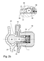
- the ball joint 24 has a, in Figs. 2a-c shown in detail, automatic adjusting device 38, whereby the bearing 24 can be readjusted in a wear of the friction clutch 12 automatically in the axial direction, ie in the direction of the release axis.
- the condyle 32 is designed in several parts with a head element 40 and a cylindrical one connected to it Base member 42 which is screwed with a thread 44 in a bore of the gear housing 34 and there radially fixed with respect to the Ausschachse 14.
- the head element 40 comprises a ball head 46 mounted in the socket pan 36 and a cylindrical pin 48 protruding therefrom, whose end section 50 terminates conically or wedge-shaped and dips into a central recess 52 of the socket element 42.
- the head member 40 is pressed in the vehicle-mounted state by the clutch lever 22 in the direction of the base member 42, whereby this is secured against falling out.
- the functional connection between the head element 40 and the base element 42 takes place in the position shown in Fig. 2a by means of a releasable locking device 54 arranged between them, which determines in particular the axial distance of the head element 40 to the base element 42.
- the pin 48 is inserted into an adjusting sleeve 56 which is displaceably arranged in the recess 52 and can be supported radially on the outside of the wall 60 of the recess 52 via clamping bodies 58, for example clamping rollers or balls.
- the clamping body 58 are axially caught on the adjusting sleeve 56 opposite axial side of a clamping body carrier 62, which in turn is held by means of a disposed between this and the bottom 64 of the recess 52 compression spring 66 in abutment.
- this designed as a clamping device locking device 54 the axial position of the head member 40 and thus the bearing 24 is fixed in the illustrated clamped state.
- the release mechanism 18 shifts in the direction of the transmission housing 34 when the friction clutch 12 is worn, as a result of which the clutch lever 22 with its end region 26 is also increasingly pivoted in this direction.
- the axial locking between the head member 40 and the base member 42 can be solved at a predetermined position of the coupling lever 22.
- 38 sensor means 68 are provided on the adjusting device, which comprise an extension 70 on the clutch lever 22 and a ring collar 72 on the adjusting sleeve 56.
- the head member 40 is pressed by the socket 36 of the clutch lever 22 in the direction of the gear housing 34 (arrow direction in Fig. 1), wherein the head member 40 is clamped in the base member 42.
- the extension 70 and the annular collar 72 are in a force-free contact and can not influence each other.
- the coupling lever is pivoted in the direction of the clutch 12, wherein the extension 72 lifts away from the stationary annular collar 72.
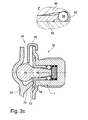
- FIG. 2c shows the end position of the ball joint 24, which is assumed at the end of life of the clutch 12 due to wear.
- the adjusting sleeve 56 is fully inserted into the recess 52 and the annular collar 72 is fixed to an end face 76 of the base member 42, whereby the entire wear compensation area of the ball joint 24 is used up.
- the fragmentary enlargement of FIG. 2c shows the locked state of the head element 40 within the base element 42 with clamp bodies 58 clamped between them.
- the condyle 32 can be provided preassembled for mounting on the gear housing 34, to which it has a securing bracket 78 which engages around an annular disc 80 formed on the base element 42 and the annular collar 72 of the head element 40 and thus holds the elements 40, 42 together as a unit.
Landscapes
- Engineering & Computer Science (AREA)
- General Engineering & Computer Science (AREA)
- Mechanical Engineering (AREA)
- Mechanical Operated Clutches (AREA)
Abstract
Description
- Die Erfindung betrifft eine Ausrückeinrichtung für eine Reibungskupplung eines Kraftfahrzeuges gemäß dem Oberbegriff des Patentanspruchs 1.
- Ausrückeinrichtungen mit einem Kupplungshebel zur Übertragung einer Betätigungskraft auf einen axial verschiebbaren Ausrücker sind allgemein bekannt. Eine derartige Anordnung geht beispielsweise aus der
DE 197 00 930 A1 hervor, bei der ein als Schwinge ausgebildeter Kupplungshebel mittels eines Kugelgelenks schwenkbar an einer Getriebewandung gelagert ist und auf welchen über das andere Ende mittels eines Stößels eines Hydraulikzylinders eine Betätigungskraft zum Betätigen einer Reibungskupplung eingeleitet werden kann. Der dort dargestellte Kupplungshebel besitzt in dessen Längsmitte eine Ausnehmung, welche einen auf einem Führungsrohr axial verschiebbar angeordneten Ausrücker umschließt und wobei eine Anlagefläche der Schwinge an einer an dem Ausrücker ausgebildeten und zur Getriebeseite konvex vorstehend gewölbten Fläche zur Kraftübertragung anliegt. - Bei der Betätigung der Reibungskupplung wird der Kupplungshebel um das Kugelgelenk verschwenkt, wozu insbesondere im Bereich zwischen dem Ausrücker und dem Angriffsbereich des Stößels ein Verschwenkraum vorgehalten werden muss. Bei einem Verschleiß der dort dargestellten "gedrückten" Reibungskupplung verlagert sich der Ausrücker im unbetätigten Zustand allmählich axial in Richtung des Getriebes. Diese Axialverschiebung hat eine in der Regel noch größere, entsprechend der am Ausrückhebel wirkenden Übersetzung, axiale Verlagerung des Angriffsbereiches des Stößels in Richtung des Getriebes zur Folge. Das heißt, dass zur Sicherung der Funktionsfähigkeit der Reibungskupplung ein noch größerer Freiraum als Verschwenkbereich vorgehalten werden muss. Daraus ergibt sich weiterhin, dass der Druckraum des Hydraulikzylinders zusätzlich zu dessen Arbeitsbereich um ein entsprechendes Ausgleichsvolumen vergrößert ausgeführt werden muss. Wenn bspw. an einem Fahrzeug das Verhältnis der wirkende Hebellängen am Ausrücker und am Angriffsbereich des Stößels, d.h. das Hebelverhältnis, 1:2 beträgt und der Ausrücker bei einem Kupplungsverschleiß über dessen Lebensdauer 10mm in Richtung Getriebe verschoben wird, so führt das am Kolben eines hydraulischen Nehmerzylinders bereits zu einer Verschiebung von 20mm, wobei jedoch in der Praxis aus Sicherheitsgründen ca. 25mm Hublänge am Nehmerzylinder vorzuhalten sind. Demgegenüber beträgt ein Arbeitshub zum Betätigen der Kupplung lediglich etwa 17mm.
Der von dem Kupplungshebel infolge eines Kupplungsverschleißes beanspruchte Freiraum steht der gegenwärtigen fortschreitenden Integration und der somit der Darstellung eines kompakten Kraftfahrzeugantriebsstranges erheblich entgegen. - Die Erfindung stellt sich die Aufgabe, den bei einem Verschleiß der Reibungskupplung, insbesondere den vom Kupplungshebel bereitzuhaltenden Vorhaltebereich zu verringern.
- Die Aufgabe wird gelöst mit einer gattungsgemäßen Ausrückeinrichtung, welche zusätzlich das im Kennzeichen des Anspruchs 1 aufgeführte Merkmal aufweist.
- Durch das Vorsehen einer automatischen Nachstelleinrichtung an der Lagerstelle des Kupplungshebels, welche diese bei einem Verschleiß der Reibungskupplung selbsttätig in axialer Richtung nachstellt, wird bei Verschleiß eine Parallelverschiebung des Kupplungshebels bezüglich dessen Lage im Neuzustand erreicht. Dadurch wird die Vergrößerung des Vorhaltebereiches durch das am Kupplungshebel wirkende Hebelverhältnis eliminiert. Der axiale Vorhaltebereich ist damit über die gesamte Länge des Kupplungshebels konstant und zu dem an einem Nehmerzylinder vorzuhaltenden Hubbereich identisch, sodass letzterer wesentlich kompakter gestaltet werden kann. Der nunmehr im Bereich des Hebels eingesparte Freiraum kann für zusätzliche Komponenten im Antriebsstrang oder zu dessen kompakterer Ausbildung genutzt werden.
- Vorteilhafte Weiterbildungen und Ausgestaltungen der Erfindung sind in den Unteransprüchen angegeben.
- Die Erfindung wird im Folgenden anhand der beigefügten Figuren beispielhaft erläutert.
- Es zeigen:
- Fig. 1
- eine schematische Darstellung einer Ausrückeinrichtung mit einer Nachstelleinrichtung,
- Fig. 2a-c
- ein Kugelgelenk zur Lagerung eines Kupplungshebels mit einer Nachstelleinrichtung in verschiedenen Positionen.
- Fig. 1 stellt schematisch ein Ausrückeinrichtung 10 für eine Kraftfahrzeugreibungskupplung 12 dar und umfasst zunächst einen axial, entlang einer Ausrückachse 14 auf einem Führungsrohr 16 verschiebbaren Ausrücker 18, der zur Übertragung einer Kupplungsbetätigungskraft mit einem als Membranfeder ausgebildeten Ausrückorgan 20 der Kupplung 12 in Wirkverbindung steht. Bezugsziffer 22 bezeichnet einen um ein Kugelgelenk 24 schwenkbar gelagerten Kupplungshebel, welcher einen Kraftaufnahmebereich 26 zur Aufnahme der Kupplungsbetätigungskraft von einem Stößel eines Hydraulikzylinders 28 und einen Kraftübertragungsbereich 30 aufweist, der sich zur Übertragung der Kupplungsbetätigungskraft mit dem Ausrücker 18 in Wirkverbindung befindet. Das Kugelgelenk 24 umfasst einen Gelenkkopf 32 als ein erstes Lagerelement, welcher an einem Getriebegehäuse 34 des Fahrzeuges festgelegt ist und ein als Gelenkpfanne 36 ausgebildetes zweites Lagerelement, welches am Kupplungshebel 22 angeordnet ist.
- Das Kugelgelenk 24 weist eine, in den Fig. 2a-c im Detail dargestellte, automatische Nachstelleinrichtung 38 auf, womit die Lagerstelle 24 bei einem Verschleiß der Reibungskupplung 12 selbsttätig in axialer Richtung, d.h. in Richtung der Ausrückachse nachgestellt werden kann. Wie in Fig. 2a erkennbar, ist der Gelenkkopf 32 mehrteilig ausgeführt mit einem Kopfelement 40 und einem mit diesem verbundenen zylinderförmigen Sockelelement 42 auf, welches mit einem Gewinde 44 in einer Bohrung des Getriebegehäuses 34 eingeschraubt und dort bezüglich der Ausrückachse 14 radial festgelegt ist. Das Kopfelement 40 umfasst einen in der Gelenkpfanne 36 gelagerten Kugelkopf 46 und einen davon abstehenden zylindrischen Zapfen 48, dessen Endabschnitt 50 konisch oder keilförmig ausläuft und in eine zentrale Ausnehmung 52 des Sockelelements 42 eintaucht. Das Kopfelement 40 wird im am Fahrzeug montierten zustand vom Kupplungshebel 22 in Richtung des Sockelelementes 42 gedrückt, wodurch dieses gegen Herausfallen gesichert ist.
- Die funktionale Verbindung zwischen dem Kopfelement 40 und dem Sockelelement 42 erfolgt in der in Fig. 2a dargestellten Lage mittels einer zwischen diesen angeordneten lösbaren Arretiereinrichtung 54, welche insbesondere den Axialabstand des Kopfelementes 40 zum dem Sockelelement 42 bestimmt. Dazu ist der Zapfen 48 in einer in der Ausnehmung 52 verschiebbar angeordneten Verstellhülse 56 eingeführt und kann sich dort über an diesem anliegende Klemmkörper 58, bspw. Klemmrollen oder -kugeln, nach radial außen an der Wandung 60 der Ausnehmung 52 abstützen. Die Klemmkörper 58 sind auf der der Verstellhülse 56 gegenüberliegenden Axialseite von einem Klemmkörperträger 62 axial gefangen, welcher seinerseits mittels einer zwischen diesem und dem Boden 64 der Ausnehmung 52 angeordnete Druckfeder 66 in Anlage gehalten wird. Mit dieser als Klemmeinrichtung ausgebildeten Arretiereinrichtung 54 ist in dem dargestellten geklemmten Zustand die axiale Lage des Kopfelementes 40 und somit der Lagerstelle 24 festgelegt.
- Wie bereits in der Beschreibungseinleitung ausgeführt, verlagert sich der Ausrücker 18 bei einem Verschleiß der Reibungskupplung 12 in Richtung des Getriebegehäuses 34, wodurch der Kupplungshebel 22 mit dessen Endbereich 26 ebenfalls zunehmend in diese Richtung verschwenkt wird. Zur Vermeidung einer solchen verschleißbedingten Schwenklage des Kupplungshebels 22 kann deshalb bei einer vorgebbaren Stellung des Kupplungshebels 22 die axiale Arretierung zwischen dem Kopfelement 40 und dem Sockelelement 42 gelöst werden. Dazu sind an der Nachstelleinrichtung 38 Sensormittel 68 vorgesehen, welche einen Fortsatz 70 am Kupplungshebel 22 und einen Ringkragen 72 an der Verstellhülse 56 umfassen.
- In dem in Fig. 2a gezeigten Neuzustand der Reibungskupplung 12 wird das Kopfelement 40 von der Gelenkpfanne 36 des Kupplungshebels 22 in Richtung des Getriebegehäuses 34 (Pfeilrichtung in Fig. 1) gedrückt, wobei das Kopfelement 40 im Sockelelement 42 festgeklemmt ist. Der Fortsatz 70 und der Ringkragen 72 sind dabei in einem kräftefreien Anlagekontakt und können sich gegenseitig nicht beeinflussen. Beim Betätigen der Reibungskupplung 12 erfolgt Verschwenkbewegung des Kupplungshebels in Richtung zur Kupplung 12, wobei der Fortsatz 72 von dem feststehenden Ringkragen 72 abhebt.
- Mit zunehmenden Verschleiß erfährt der Kupplungshebel 22 im Vergleich zu dessen Verschwenk-Ausgangslage gemäß Fig. 1 eine allmähliche Verkippung, wobei der Kraftaufnahmebereich 26 und der Fortsatz 70 weiter in Richtung des Getriebegehäuses 34 verlagert werden. Sobald eine in Fig. 2b dargestellte kritische Schwenklage des Kupplungshebels 22 erreicht ist, wird der Ringkragen 72 der Verstellhülse 56 durch den Fortsatz 70 in Richtung des Getriebegehäuses 34 belastet, wodurch die Verstellhülse 56 entgegen der Wirkung der Druckfeder 66 in Richtung des Bodens 64 verschoben wird und dabei die Klemmkörper 58 ebenfalls in diese Richtung verlagert werden. Infolge der konischen bzw. keilförmigen Ausgestaltung des Zapfens 48 bildet sich zwischen diesem und den Klemmkörpern 58 ein Radialspalt 74 aus, wodurch die bisher wirkende Arretierung des Kopfelementes 40 kurzeitig aufgehoben wird, bis dieses durch die über die Gelenkpfanne 36 wirkende Kraft weiter in die Ausnehmung 52 gepresst wird und sich bei Anlage an den Klemmkörpern 58 erneut verklemmen kann. Damit ist bis zum Auftreten eines weiteren, von der Nachstelleinrichtung 38 detektierten Verschleißes eine stabile Position erreicht.
- Fig. 2c zeigt schließlich die Endstellung des Kugelgelenks 24, die am verschleißbedingten Lebensdauerende der Kupplung 12 eingenommen wird. Die Verstellhülse 56 ist vollständig in die Ausnehmung 52 eingeführt und der Ringkragen 72 liegt fest an einer Stirnfläche 76 des Sockelelementes 42 an, wodurch der gesamte Verschleißausgleichsbereich des Kugelgelenks 24 aufgebraucht ist. Die ausschnittweise Vergrößerung der Fig. 2c zeigt den arretierten Zustand des Kopfelementes 40 innerhalb des Sockelelementes 42 mit zwischen diesen eingeklemmten Klemmkörpern 58.
Der Gelenkkopf 32 kann vormontiert zu dessen Montage am Getriebegehäuse 34 bereitgestellt werden, wozu dieser einen Sicherungsbügel 78 aufweist, der eine am Sockelelement 42 ausgebildete Ringscheibe 80 und den Ringkragen 72 des Kopfelementes 40 umgreift und somit die Elemente 40, 42 als Einheit zusammenhält.
Claims (5)
- Ausrückeinrichtung (10) für eine Reibungskupplung (12) eines Kraftfahrzeuges, umfassend- einen axial, entlang einer Ausrückachse (14) verschiebbaren Ausrücker (18), der zur Übertragung einer Kupplungsbetätigungskraft mit einem Ausrückorgan (20) der Kupplung (12) in Wirkverbindung steht,- einen um eine Lagerstelle (24) schwenkbar gelagerten Kupplungshebel (22), welcher- einen Kraftaufnahmebereich (26) zur Aufnahme der Kupplungsbetätigungskraft von einem Stellglied (28) und- einen Kraftübertragungsbereich (30) aufweist, der sich zur Übertragung der Kupplungsbetätigungskraft mit dem Ausrücker (18) in Wirkverbindung befindet, wobei die Lagerstelle (24) ein erstes Lagerelement (32) an einer zu der Ausrückeinrichtung (10) ortsfesten Baugruppe (34) und ein zweites Lagerelement (36) am Kupplungshebel (22) aufweist,
dadurch gekennzeichnet,
dass die Lagerstelle (24) eine automatische Nachstelleinrichtung (38) aufweist, womit die Lagerstelle (24) bei einem Verschleiß der Reibungskupplung (12) selbsttätig in axialer Richtung nachgestellt wird. - Ausrückeinrichtung nach Anspruch 1,
dadurch gekennzeichnet,
dass zur Darstellung der Nachstelleinrichtung (38) das erste Lagerelement (32) ein Sockelelement (42) zur Anordnung an der ortsfesten Baugruppe (34), ein gegenüber dem Sockelelement (42) verlagerbares Kopfelement (40) zur Anlage an dem zweiten Lagerelement (36) und eine funktional zwischen diesen angeordnete lösbare Arretiereinrichtung (54) zur gegenseitigen Lagefestlegung des Sockelelements (42) zum Kopfelement (40) aufweist. - Ausrückeinrichtung nach Anspruch 1 oder 2,
dadurch gekennzeichnet,
dass die Nachstelleinrichtung (38) Sensormittel (68) zur Sensierung eines Verschleißes der Reibungskupplung (12) und zur Beeinflussung der Arretiereinrichtung (54) aufweisen. - Ausrückeinrichtung nach Anspruch 3,
dadurch gekennzeichnet,
dass die Sensormittel (68) einen Fortsatz (70) am Kupplungshebel (22) aufweisen, der bei Erreichen einer vorgegebenen Stellung des Kupplungshebels (22) mit der Arretiereinrichtung (54) in Wirkverbindung treten kann. - Ausrückeinrichtung nach einem der Ansprüche 1-4,
dadurch gekennzeichnet,
dass die Arretiereinrichtung (54) als Klemmeinrichtung ausgebildet ist.
Priority Applications (3)
| Application Number | Priority Date | Filing Date | Title |
|---|---|---|---|
| DE502005006689T DE502005006689D1 (de) | 2005-03-17 | 2005-03-17 | Ausrückeinrichtung für eine Reibungskupplung eines Kraftfahrzeuges |
| EP05005799A EP1703160B1 (de) | 2005-03-17 | 2005-03-17 | Ausrückeinrichtung für eine Reibungskupplung eines Kraftfahrzeuges |
| AT05005799T ATE423918T1 (de) | 2005-03-17 | 2005-03-17 | Ausrückeinrichtung für eine reibungskupplung eines kraftfahrzeuges |
Applications Claiming Priority (1)
| Application Number | Priority Date | Filing Date | Title |
|---|---|---|---|
| EP05005799A EP1703160B1 (de) | 2005-03-17 | 2005-03-17 | Ausrückeinrichtung für eine Reibungskupplung eines Kraftfahrzeuges |
Publications (2)
| Publication Number | Publication Date |
|---|---|
| EP1703160A1 true EP1703160A1 (de) | 2006-09-20 |
| EP1703160B1 EP1703160B1 (de) | 2009-02-25 |
Family
ID=34934318
Family Applications (1)
| Application Number | Title | Priority Date | Filing Date |
|---|---|---|---|
| EP05005799A Expired - Lifetime EP1703160B1 (de) | 2005-03-17 | 2005-03-17 | Ausrückeinrichtung für eine Reibungskupplung eines Kraftfahrzeuges |
Country Status (3)
| Country | Link |
|---|---|
| EP (1) | EP1703160B1 (de) |
| AT (1) | ATE423918T1 (de) |
| DE (1) | DE502005006689D1 (de) |
Cited By (7)
| Publication number | Priority date | Publication date | Assignee | Title |
|---|---|---|---|---|
| FR2942012A1 (fr) * | 2009-02-12 | 2010-08-13 | Valeo Embrayages | Mecanisme de commande pour un systeme d'embrayage a friction comportant un dispositif de rattrapage de jeu |
| EP2354582A1 (de) * | 2010-02-10 | 2011-08-10 | Valeo Embrayages | Betätigungsvorrichtung mit Verschleissausgleich für eine Reibungskupplung |
| DE102011102103A1 (de) * | 2011-05-20 | 2012-11-22 | Getrag Getriebe- Und Zahnradfabrik Hermann Hagenmeyer Gmbh & Cie Kg | Aktuatoranordnung für eine Kupplungsanordnung |
| AT516355A1 (de) * | 2014-09-25 | 2016-04-15 | Avl Commercial Driveline & Tractor Engineering Gmbh | Ausrückzylinder zum betätigen eines reibungselementes |
| DE102010049907B4 (de) * | 2009-11-04 | 2017-07-20 | GM Global Technology Operations LLC (n. d. Ges. d. Staates Delaware) | Selbsteinstellende Mechanismen für Kupplungen |
| WO2023159720A1 (zh) * | 2022-02-23 | 2023-08-31 | 浙江鑫可传动科技有限公司 | 离合器的操纵机构 |
| JP2024510362A (ja) * | 2022-02-23 | 2024-03-07 | 浙江▲シン▼可伝動科技有限公司 | クラッチの作動機構 |
Citations (3)
| Publication number | Priority date | Publication date | Assignee | Title |
|---|---|---|---|---|
| US4763766A (en) * | 1985-04-05 | 1988-08-16 | Valeo | Control linkage for coupling device |
| EP0699844A1 (de) * | 1994-08-30 | 1996-03-06 | Société Anonyme dite: REGIE NATIONALE DES USINES RENAULT | Kupplungsbetätigungseinrichtung mit Nachstellvorrichtung |
| DE19700930A1 (de) * | 1996-03-21 | 1997-09-25 | Fichtel & Sachs Ag | Ausrückvorrichtung für eine Reibungskupplung |
-
2005
- 2005-03-17 DE DE502005006689T patent/DE502005006689D1/de not_active Expired - Lifetime
- 2005-03-17 AT AT05005799T patent/ATE423918T1/de not_active IP Right Cessation
- 2005-03-17 EP EP05005799A patent/EP1703160B1/de not_active Expired - Lifetime
Patent Citations (3)
| Publication number | Priority date | Publication date | Assignee | Title |
|---|---|---|---|---|
| US4763766A (en) * | 1985-04-05 | 1988-08-16 | Valeo | Control linkage for coupling device |
| EP0699844A1 (de) * | 1994-08-30 | 1996-03-06 | Société Anonyme dite: REGIE NATIONALE DES USINES RENAULT | Kupplungsbetätigungseinrichtung mit Nachstellvorrichtung |
| DE19700930A1 (de) * | 1996-03-21 | 1997-09-25 | Fichtel & Sachs Ag | Ausrückvorrichtung für eine Reibungskupplung |
Cited By (13)
| Publication number | Priority date | Publication date | Assignee | Title |
|---|---|---|---|---|
| CN102317639B (zh) * | 2009-02-12 | 2014-07-23 | Valeo离合器公司 | 包括间隙调整装置的用于摩擦离合器系统的控制机构 |
| WO2010092278A1 (fr) * | 2009-02-12 | 2010-08-19 | Valeo Embrayages | Mecanisme de commande pour un systeme d'embrayage a friction comportant un dispositif de rattrapage de jeu |
| FR2942012A1 (fr) * | 2009-02-12 | 2010-08-13 | Valeo Embrayages | Mecanisme de commande pour un systeme d'embrayage a friction comportant un dispositif de rattrapage de jeu |
| DE102010049907B4 (de) * | 2009-11-04 | 2017-07-20 | GM Global Technology Operations LLC (n. d. Ges. d. Staates Delaware) | Selbsteinstellende Mechanismen für Kupplungen |
| FR2956173A1 (fr) * | 2010-02-10 | 2011-08-12 | Valeo Embrayages | Mecanisme de commande pour un systeme d'embrayage a friction comportant un dispositif de rattrapage de jeu. |
| EP2354582A1 (de) * | 2010-02-10 | 2011-08-10 | Valeo Embrayages | Betätigungsvorrichtung mit Verschleissausgleich für eine Reibungskupplung |
| DE102011102103A1 (de) * | 2011-05-20 | 2012-11-22 | Getrag Getriebe- Und Zahnradfabrik Hermann Hagenmeyer Gmbh & Cie Kg | Aktuatoranordnung für eine Kupplungsanordnung |
| DE102011102103B4 (de) * | 2011-05-20 | 2014-08-07 | Getrag Getriebe- Und Zahnradfabrik Hermann Hagenmeyer Gmbh & Cie Kg | Aktuatoranordnung für eine Kupplungsanordnung |
| AT516355A1 (de) * | 2014-09-25 | 2016-04-15 | Avl Commercial Driveline & Tractor Engineering Gmbh | Ausrückzylinder zum betätigen eines reibungselementes |
| AT516355B1 (de) * | 2014-09-25 | 2016-08-15 | Avl Commercial Driveline & Tractor Eng Gmbh | Ausrückzylinder zum betätigen eines reibungselementes |
| WO2023159720A1 (zh) * | 2022-02-23 | 2023-08-31 | 浙江鑫可传动科技有限公司 | 离合器的操纵机构 |
| JP2024510362A (ja) * | 2022-02-23 | 2024-03-07 | 浙江▲シン▼可伝動科技有限公司 | クラッチの作動機構 |
| US12181003B2 (en) | 2022-02-23 | 2024-12-31 | Zhejiang Xinke Transmission Technology Co., Ltd | Control mechanism for clutch |
Also Published As
| Publication number | Publication date |
|---|---|
| EP1703160B1 (de) | 2009-02-25 |
| DE502005006689D1 (de) | 2009-04-09 |
| ATE423918T1 (de) | 2009-03-15 |
Similar Documents
| Publication | Publication Date | Title |
|---|---|---|
| DE102015008709B4 (de) | Parksperrenmodul sowie Kraftfahrzeuggetriebe | |
| DE102010049907B4 (de) | Selbsteinstellende Mechanismen für Kupplungen | |
| DE102015111175A1 (de) | Hydraulikventil und Pleuel mit einem Hydraulikventil | |
| EP1608940B1 (de) | Vorrichtung zum erfassen einer betätigungskraft eines bremspedals und bremsanlage | |
| EP1438504B8 (de) | Hubkolbenmaschine mit einer schiebehülse | |
| EP1703160B1 (de) | Ausrückeinrichtung für eine Reibungskupplung eines Kraftfahrzeuges | |
| EP2426018A1 (de) | Fußhebelwerk für ein Fahrzeug | |
| EP0386330A1 (de) | Kupplungsbetätigungsvorrichtung | |
| DE102008044046B4 (de) | Druckplattenbaugruppe, insbesondere für eine Reibungskupplung mit automatischem Verschleißausgleich | |
| EP2122191B1 (de) | Ausrückanordnung für eine kupplung mit verschleissnachstellung | |
| WO1997024547A1 (de) | Spannvorrichtung, insbesondere für eine steckkupplung | |
| DE102005049056B4 (de) | Kupplungsbetätigungsvorrichtung | |
| EP2009308B1 (de) | Kupplungsausrücksystem | |
| EP2824346B1 (de) | Reibungskupplung für Antriebsstrang eines Kraftfahrzeuges | |
| EP1996426A1 (de) | Anordnung zur druckbeaufschlagung eines hydraulischen systems | |
| EP1703161B1 (de) | Ausrückeinrichtung für eine Kraftfahrzeugkupplung | |
| DE112005001646B4 (de) | Positionssensor für einen Fahrzeugmechanismus | |
| DE102017121807A1 (de) | Nehmerzylinder mit Taumelausgleich im Dichtungsträger | |
| DE102008043247B3 (de) | Hypozykloidische Ausrückeinrichtung für eine Kraftfahrzeugkupplung | |
| DE19737054C5 (de) | Reibungskupplung mit fremdkraftbetriebener Betätigungseinrichtung | |
| DE102021122699A1 (de) | Hydraulikzylinder | |
| DE102015217789A1 (de) | Druckzylinder, insbesondere Geberzylinder, mit bewegter Dichtung sowie bewegter Hülse und variabler Ausrückkraft | |
| DE10352941A1 (de) | Druckmittelzylinder für eine hydraulische Betätigunseinrichtung | |
| DE102014210349A1 (de) | Betätigungseinrichtung | |
| EP2233751A2 (de) | Druckmittelzylinder mit optimierter Kolbenführung |
Legal Events
| Date | Code | Title | Description |
|---|---|---|---|
| PUAI | Public reference made under article 153(3) epc to a published international application that has entered the european phase |
Free format text: ORIGINAL CODE: 0009012 |
|
| 17P | Request for examination filed |
Effective date: 20051126 |
|
| AK | Designated contracting states |
Kind code of ref document: A1 Designated state(s): AT BE BG CH CY CZ DE DK EE ES FI FR GB GR HU IE IS IT LI LT LU MC NL PL PT RO SE SI SK TR |
|
| AX | Request for extension of the european patent |
Extension state: AL BA HR LV MK YU |
|
| APBN | Date of receipt of notice of appeal recorded |
Free format text: ORIGINAL CODE: EPIDOSNNOA2E |
|
| AKX | Designation fees paid |
Designated state(s): AT BE BG CH CY CZ DE DK EE ES FI FR GB GR HU IE IS IT LI LT LU MC NL PL PT RO SE SI SK TR |
|
| APBR | Date of receipt of statement of grounds of appeal recorded |
Free format text: ORIGINAL CODE: EPIDOSNNOA3E |
|
| APBV | Interlocutory revision of appeal recorded |
Free format text: ORIGINAL CODE: EPIDOSNIRAPE |
|
| GRAP | Despatch of communication of intention to grant a patent |
Free format text: ORIGINAL CODE: EPIDOSNIGR1 |
|
| GRAS | Grant fee paid |
Free format text: ORIGINAL CODE: EPIDOSNIGR3 |
|
| GRAA | (expected) grant |
Free format text: ORIGINAL CODE: 0009210 |
|
| AK | Designated contracting states |
Kind code of ref document: B1 Designated state(s): AT BE BG CH CY CZ DE DK EE ES FI FR GB GR HU IE IS IT LI LT LU MC NL PL PT RO SE SI SK TR |
|
| REG | Reference to a national code |
Ref country code: GB Ref legal event code: FG4D Free format text: NOT ENGLISH |
|
| REG | Reference to a national code |
Ref country code: CH Ref legal event code: EP |
|
| REG | Reference to a national code |
Ref country code: IE Ref legal event code: FG4D Free format text: LANGUAGE OF EP DOCUMENT: GERMAN |
|
| REF | Corresponds to: |
Ref document number: 502005006689 Country of ref document: DE Date of ref document: 20090409 Kind code of ref document: P |
|
| PG25 | Lapsed in a contracting state [announced via postgrant information from national office to epo] |
Ref country code: FI Free format text: LAPSE BECAUSE OF FAILURE TO SUBMIT A TRANSLATION OF THE DESCRIPTION OR TO PAY THE FEE WITHIN THE PRESCRIBED TIME-LIMIT Effective date: 20090225 Ref country code: SI Free format text: LAPSE BECAUSE OF FAILURE TO SUBMIT A TRANSLATION OF THE DESCRIPTION OR TO PAY THE FEE WITHIN THE PRESCRIBED TIME-LIMIT Effective date: 20090225 Ref country code: NL Free format text: LAPSE BECAUSE OF FAILURE TO SUBMIT A TRANSLATION OF THE DESCRIPTION OR TO PAY THE FEE WITHIN THE PRESCRIBED TIME-LIMIT Effective date: 20090225 Ref country code: LT Free format text: LAPSE BECAUSE OF FAILURE TO SUBMIT A TRANSLATION OF THE DESCRIPTION OR TO PAY THE FEE WITHIN THE PRESCRIBED TIME-LIMIT Effective date: 20090225 |
|
| NLV1 | Nl: lapsed or annulled due to failure to fulfill the requirements of art. 29p and 29m of the patents act | ||
| PG25 | Lapsed in a contracting state [announced via postgrant information from national office to epo] |
Ref country code: PL Free format text: LAPSE BECAUSE OF FAILURE TO SUBMIT A TRANSLATION OF THE DESCRIPTION OR TO PAY THE FEE WITHIN THE PRESCRIBED TIME-LIMIT Effective date: 20090225 Ref country code: SE Free format text: LAPSE BECAUSE OF FAILURE TO SUBMIT A TRANSLATION OF THE DESCRIPTION OR TO PAY THE FEE WITHIN THE PRESCRIBED TIME-LIMIT Effective date: 20090525 Ref country code: IS Free format text: LAPSE BECAUSE OF FAILURE TO SUBMIT A TRANSLATION OF THE DESCRIPTION OR TO PAY THE FEE WITHIN THE PRESCRIBED TIME-LIMIT Effective date: 20090625 |
|
| REG | Reference to a national code |
Ref country code: IE Ref legal event code: FD4D |
|
| BERE | Be: lapsed |
Owner name: ZF FRIEDRICHSHAFEN A.G. Effective date: 20090331 |
|
| PG25 | Lapsed in a contracting state [announced via postgrant information from national office to epo] |
Ref country code: PT Free format text: LAPSE BECAUSE OF FAILURE TO SUBMIT A TRANSLATION OF THE DESCRIPTION OR TO PAY THE FEE WITHIN THE PRESCRIBED TIME-LIMIT Effective date: 20090812 Ref country code: MC Free format text: LAPSE BECAUSE OF NON-PAYMENT OF DUE FEES Effective date: 20090331 Ref country code: IE Free format text: LAPSE BECAUSE OF FAILURE TO SUBMIT A TRANSLATION OF THE DESCRIPTION OR TO PAY THE FEE WITHIN THE PRESCRIBED TIME-LIMIT Effective date: 20090225 Ref country code: ES Free format text: LAPSE BECAUSE OF FAILURE TO SUBMIT A TRANSLATION OF THE DESCRIPTION OR TO PAY THE FEE WITHIN THE PRESCRIBED TIME-LIMIT Effective date: 20090605 Ref country code: DK Free format text: LAPSE BECAUSE OF FAILURE TO SUBMIT A TRANSLATION OF THE DESCRIPTION OR TO PAY THE FEE WITHIN THE PRESCRIBED TIME-LIMIT Effective date: 20090225 Ref country code: CZ Free format text: LAPSE BECAUSE OF FAILURE TO SUBMIT A TRANSLATION OF THE DESCRIPTION OR TO PAY THE FEE WITHIN THE PRESCRIBED TIME-LIMIT Effective date: 20090225 Ref country code: EE Free format text: LAPSE BECAUSE OF FAILURE TO SUBMIT A TRANSLATION OF THE DESCRIPTION OR TO PAY THE FEE WITHIN THE PRESCRIBED TIME-LIMIT Effective date: 20090225 |
|
| REG | Reference to a national code |
Ref country code: CH Ref legal event code: PL |
|
| PG25 | Lapsed in a contracting state [announced via postgrant information from national office to epo] |
Ref country code: SK Free format text: LAPSE BECAUSE OF FAILURE TO SUBMIT A TRANSLATION OF THE DESCRIPTION OR TO PAY THE FEE WITHIN THE PRESCRIBED TIME-LIMIT Effective date: 20090225 Ref country code: RO Free format text: LAPSE BECAUSE OF FAILURE TO SUBMIT A TRANSLATION OF THE DESCRIPTION OR TO PAY THE FEE WITHIN THE PRESCRIBED TIME-LIMIT Effective date: 20090225 |
|
| PLBE | No opposition filed within time limit |
Free format text: ORIGINAL CODE: 0009261 |
|
| STAA | Information on the status of an ep patent application or granted ep patent |
Free format text: STATUS: NO OPPOSITION FILED WITHIN TIME LIMIT |
|
| GBPC | Gb: european patent ceased through non-payment of renewal fee |
Effective date: 20090525 |
|
| PG25 | Lapsed in a contracting state [announced via postgrant information from national office to epo] |
Ref country code: BG Free format text: LAPSE BECAUSE OF FAILURE TO SUBMIT A TRANSLATION OF THE DESCRIPTION OR TO PAY THE FEE WITHIN THE PRESCRIBED TIME-LIMIT Effective date: 20090525 Ref country code: LI Free format text: LAPSE BECAUSE OF NON-PAYMENT OF DUE FEES Effective date: 20090331 Ref country code: CH Free format text: LAPSE BECAUSE OF NON-PAYMENT OF DUE FEES Effective date: 20090331 |
|
| 26N | No opposition filed |
Effective date: 20091126 |
|
| PG25 | Lapsed in a contracting state [announced via postgrant information from national office to epo] |
Ref country code: BE Free format text: LAPSE BECAUSE OF NON-PAYMENT OF DUE FEES Effective date: 20090331 |
|
| PG25 | Lapsed in a contracting state [announced via postgrant information from national office to epo] |
Ref country code: GB Free format text: LAPSE BECAUSE OF NON-PAYMENT OF DUE FEES Effective date: 20090525 |
|
| PGFP | Annual fee paid to national office [announced via postgrant information from national office to epo] |
Ref country code: FR Payment date: 20100324 Year of fee payment: 6 |
|
| PG25 | Lapsed in a contracting state [announced via postgrant information from national office to epo] |
Ref country code: AT Free format text: LAPSE BECAUSE OF NON-PAYMENT OF DUE FEES Effective date: 20090317 |
|
| PGFP | Annual fee paid to national office [announced via postgrant information from national office to epo] |
Ref country code: DE Payment date: 20100422 Year of fee payment: 6 |
|
| PG25 | Lapsed in a contracting state [announced via postgrant information from national office to epo] |
Ref country code: GR Free format text: LAPSE BECAUSE OF FAILURE TO SUBMIT A TRANSLATION OF THE DESCRIPTION OR TO PAY THE FEE WITHIN THE PRESCRIBED TIME-LIMIT Effective date: 20090526 |
|
| PG25 | Lapsed in a contracting state [announced via postgrant information from national office to epo] |
Ref country code: IT Free format text: LAPSE BECAUSE OF FAILURE TO SUBMIT A TRANSLATION OF THE DESCRIPTION OR TO PAY THE FEE WITHIN THE PRESCRIBED TIME-LIMIT Effective date: 20090225 |
|
| PG25 | Lapsed in a contracting state [announced via postgrant information from national office to epo] |
Ref country code: LU Free format text: LAPSE BECAUSE OF NON-PAYMENT OF DUE FEES Effective date: 20090317 |
|
| PG25 | Lapsed in a contracting state [announced via postgrant information from national office to epo] |
Ref country code: HU Free format text: LAPSE BECAUSE OF FAILURE TO SUBMIT A TRANSLATION OF THE DESCRIPTION OR TO PAY THE FEE WITHIN THE PRESCRIBED TIME-LIMIT Effective date: 20090826 |
|
| PG25 | Lapsed in a contracting state [announced via postgrant information from national office to epo] |
Ref country code: TR Free format text: LAPSE BECAUSE OF FAILURE TO SUBMIT A TRANSLATION OF THE DESCRIPTION OR TO PAY THE FEE WITHIN THE PRESCRIBED TIME-LIMIT Effective date: 20090225 |
|
| PG25 | Lapsed in a contracting state [announced via postgrant information from national office to epo] |
Ref country code: CY Free format text: LAPSE BECAUSE OF FAILURE TO SUBMIT A TRANSLATION OF THE DESCRIPTION OR TO PAY THE FEE WITHIN THE PRESCRIBED TIME-LIMIT Effective date: 20090225 |
|
| REG | Reference to a national code |
Ref country code: FR Ref legal event code: ST Effective date: 20111130 |
|
| PG25 | Lapsed in a contracting state [announced via postgrant information from national office to epo] |
Ref country code: DE Free format text: LAPSE BECAUSE OF NON-PAYMENT OF DUE FEES Effective date: 20111001 Ref country code: FR Free format text: LAPSE BECAUSE OF NON-PAYMENT OF DUE FEES Effective date: 20110331 |
|
| REG | Reference to a national code |
Ref country code: DE Ref legal event code: R119 Ref document number: 502005006689 Country of ref document: DE Effective date: 20111001 |