EP1703114A1 - Bruit du moteur - Google Patents
Bruit du moteur Download PDFInfo
- Publication number
- EP1703114A1 EP1703114A1 EP06251122A EP06251122A EP1703114A1 EP 1703114 A1 EP1703114 A1 EP 1703114A1 EP 06251122 A EP06251122 A EP 06251122A EP 06251122 A EP06251122 A EP 06251122A EP 1703114 A1 EP1703114 A1 EP 1703114A1
- Authority
- EP
- European Patent Office
- Prior art keywords
- nozzle
- undulations
- bumps
- jet
- convergent
- Prior art date
- Legal status (The legal status is an assumption and is not a legal conclusion. Google has not performed a legal analysis and makes no representation as to the accuracy of the status listed.)
- Granted
Links
- 230000035939 shock Effects 0.000 claims abstract description 30
- 238000011144 upstream manufacturing Methods 0.000 claims description 24
- 239000012781 shape memory material Substances 0.000 claims description 20
- 238000009826 distribution Methods 0.000 claims description 19
- 230000009467 reduction Effects 0.000 claims description 13
- 230000004323 axial length Effects 0.000 claims description 9
- 239000000463 material Substances 0.000 claims description 5
- 239000012858 resilient material Substances 0.000 claims description 3
- 230000000638 stimulation Effects 0.000 claims description 2
- 230000001629 suppression Effects 0.000 abstract description 19
- 238000013459 approach Methods 0.000 abstract description 2
- 230000001419 dependent effect Effects 0.000 description 7
- 230000000694 effects Effects 0.000 description 6
- 230000008859 change Effects 0.000 description 5
- 238000013461 design Methods 0.000 description 3
- 230000007246 mechanism Effects 0.000 description 3
- 239000000203 mixture Substances 0.000 description 3
- 230000015556 catabolic process Effects 0.000 description 2
- 230000001427 coherent effect Effects 0.000 description 2
- 230000006870 function Effects 0.000 description 2
- 230000001788 irregular Effects 0.000 description 2
- 238000004519 manufacturing process Methods 0.000 description 2
- RTAQQCXQSZGOHL-UHFFFAOYSA-N Titanium Chemical compound [Ti] RTAQQCXQSZGOHL-UHFFFAOYSA-N 0.000 description 1
- 238000005452 bending Methods 0.000 description 1
- 230000008901 benefit Effects 0.000 description 1
- 230000001351 cycling effect Effects 0.000 description 1
- 230000007423 decrease Effects 0.000 description 1
- 230000003247 decreasing effect Effects 0.000 description 1
- 238000006731 degradation reaction Methods 0.000 description 1
- 230000001627 detrimental effect Effects 0.000 description 1
- 230000007613 environmental effect Effects 0.000 description 1
- 230000003628 erosive effect Effects 0.000 description 1
- 238000005562 fading Methods 0.000 description 1
- 238000009499 grossing Methods 0.000 description 1
- 238000003780 insertion Methods 0.000 description 1
- 230000037431 insertion Effects 0.000 description 1
- 230000003993 interaction Effects 0.000 description 1
- 238000000034 method Methods 0.000 description 1
- 238000012986 modification Methods 0.000 description 1
- 230000004048 modification Effects 0.000 description 1
- 230000010355 oscillation Effects 0.000 description 1
- 230000008569 process Effects 0.000 description 1
- 238000007789 sealing Methods 0.000 description 1
- 229910001285 shape-memory alloy Inorganic materials 0.000 description 1
- 229910052719 titanium Inorganic materials 0.000 description 1
- 239000010936 titanium Substances 0.000 description 1
Images


Classifications
-
- F—MECHANICAL ENGINEERING; LIGHTING; HEATING; WEAPONS; BLASTING
- F02—COMBUSTION ENGINES; HOT-GAS OR COMBUSTION-PRODUCT ENGINE PLANTS
- F02K—JET-PROPULSION PLANTS
- F02K1/00—Plants characterised by the form or arrangement of the jet pipe or nozzle; Jet pipes or nozzles peculiar thereto
- F02K1/46—Nozzles having means for adding air to the jet or for augmenting the mixing region between the jet and the ambient air, e.g. for silencing
- F02K1/48—Corrugated nozzles
-
- B—PERFORMING OPERATIONS; TRANSPORTING
- B64—AIRCRAFT; AVIATION; COSMONAUTICS
- B64D—EQUIPMENT FOR FITTING IN OR TO AIRCRAFT; FLIGHT SUITS; PARACHUTES; ARRANGEMENT OR MOUNTING OF POWER PLANTS OR PROPULSION TRANSMISSIONS IN AIRCRAFT
- B64D33/00—Arrangements in aircraft of power plant parts or auxiliaries not otherwise provided for
- B64D33/04—Arrangements in aircraft of power plant parts or auxiliaries not otherwise provided for of exhaust outlets or jet pipes
- B64D33/06—Silencing exhaust or propulsion jets
-
- F—MECHANICAL ENGINEERING; LIGHTING; HEATING; WEAPONS; BLASTING
- F02—COMBUSTION ENGINES; HOT-GAS OR COMBUSTION-PRODUCT ENGINE PLANTS
- F02K—JET-PROPULSION PLANTS
- F02K1/00—Plants characterised by the form or arrangement of the jet pipe or nozzle; Jet pipes or nozzles peculiar thereto
- F02K1/46—Nozzles having means for adding air to the jet or for augmenting the mixing region between the jet and the ambient air, e.g. for silencing
-
- F—MECHANICAL ENGINEERING; LIGHTING; HEATING; WEAPONS; BLASTING
- F02—COMBUSTION ENGINES; HOT-GAS OR COMBUSTION-PRODUCT ENGINE PLANTS
- F02K—JET-PROPULSION PLANTS
- F02K1/00—Plants characterised by the form or arrangement of the jet pipe or nozzle; Jet pipes or nozzles peculiar thereto
- F02K1/78—Other construction of jet pipes
- F02K1/82—Jet pipe walls, e.g. liners
- F02K1/827—Sound absorbing structures or liners
-
- F—MECHANICAL ENGINEERING; LIGHTING; HEATING; WEAPONS; BLASTING
- F05—INDEXING SCHEMES RELATING TO ENGINES OR PUMPS IN VARIOUS SUBCLASSES OF CLASSES F01-F04
- F05D—INDEXING SCHEME FOR ASPECTS RELATING TO NON-POSITIVE-DISPLACEMENT MACHINES OR ENGINES, GAS-TURBINES OR JET-PROPULSION PLANTS
- F05D2240/00—Components
- F05D2240/10—Stators
- F05D2240/12—Fluid guiding means, e.g. vanes
- F05D2240/127—Vortex generators, turbulators, or the like, for mixing
-
- F—MECHANICAL ENGINEERING; LIGHTING; HEATING; WEAPONS; BLASTING
- F05—INDEXING SCHEMES RELATING TO ENGINES OR PUMPS IN VARIOUS SUBCLASSES OF CLASSES F01-F04
- F05D—INDEXING SCHEME FOR ASPECTS RELATING TO NON-POSITIVE-DISPLACEMENT MACHINES OR ENGINES, GAS-TURBINES OR JET-PROPULSION PLANTS
- F05D2260/00—Function
- F05D2260/96—Preventing, counteracting or reducing vibration or noise
-
- Y—GENERAL TAGGING OF NEW TECHNOLOGICAL DEVELOPMENTS; GENERAL TAGGING OF CROSS-SECTIONAL TECHNOLOGIES SPANNING OVER SEVERAL SECTIONS OF THE IPC; TECHNICAL SUBJECTS COVERED BY FORMER USPC CROSS-REFERENCE ART COLLECTIONS [XRACs] AND DIGESTS
- Y02—TECHNOLOGIES OR APPLICATIONS FOR MITIGATION OR ADAPTATION AGAINST CLIMATE CHANGE
- Y02T—CLIMATE CHANGE MITIGATION TECHNOLOGIES RELATED TO TRANSPORTATION
- Y02T50/00—Aeronautics or air transport
- Y02T50/60—Efficient propulsion technologies, e.g. for aircraft
Definitions
- the present invention relates to gas turbine engine noise and more particularly to jet noise under cruise conditions.
- Shock cell noise is generated as the turbulence of the jet shear layer passes through and interacts with the shock structure of the jet (see Harper-Bourne, M. and Fisher, M.J., 1973, "The Noise from Shock Waves in Supersonic Jets", Proceedings (No. 131) of the AGARD Conference on Noise Mechanisms, Brussels, Belgium ). If one considers a cross section through half of a typical high bypass ratio civil engine nozzle system, with the bypass jet imperfectly expanded, there is a shock structure set up in the bypass stream. The shear layer between the flight stream and the bypass stream becomes turbulent as it develops and the turbulence that results convects through the shock structure generating noise.
- the region in which the shock cell noise is generated may be several nozzle diameters downstream of the nozzle exit plane.
- Shock cell noise may be reduced by previous serrations at the nozzle exit that enhance the mixing of the shear layer so that the turbulence intensity is lower in regions where the turbulence interacts with the shock structure.
- serrated nozzles consist of flaps or tabs added to or cut out of a nozzle so as to generate circumferential flow non-uniformities.
- the circumferential flow non-uniformities enhance mixing of the jet thereby breaking up coherent structures leading to lower noise.
- the increased surface area of serrations also increases the drag. Increased surface area also increases overall weight.
- a nozzle for a gas turbine engine comprising a nozzle surface including a plurality of undulations to vary available cross sectional area across the nozzle between the nozzle surface and an opposed surface of the nozzle over a desired convergent-divergent ratio range for noise control of a jet passing through the nozzle in use.
- the undulations also provide variation in the angle of flow of the jet passing through the nozzle.
- the variation in cross sectional area is adjusted to provide stimulation in mixing of a shear layer of the jet for relative noise reduction in comparison with that without mixing of the shear layer of the jet. Additionally, the undulations alter the repeat cycle and/or provide variation of intensity of shock cells generated by the jet.
- the undulations comprise bumps formed in the nozzle surface.
- the undulations are sinusoidal in a circumferential direction or in a plane perpendicular to a jet flow direction in use.
- the undulations each comprise maximum amplitude, the maximum amplitude situated a distance between 2% and 15% of the nozzle diameter along the nozzle surface upstream from the nozzle exit plane.
- the maximum amplitude situated a distance equivalent to 6% of the nozzle diameter upstream of nozzle exit plane.
- the undulations each comprise a maximum amplitude, the maximum amplitude situated within a distance equivalent to +/- 2% of the nozzle diameter along the nozzle surface from the nozzle throat plane.
- the approximate cross-section shape of the undulations are from the group comprising triangular, trapezoidal, part-circular, sinusoidal and asymmetric-sinusoidal.
- the undulations have an aerodynamically smooth gradual spline in an axial direction of jet flow in use.
- the aerodynamically smooth spline is between radii at three fixed axial locations along the nozzle surface from the nozzle exit plane, one radii within a distance upstream equivalent to 20% of the nozzle diameter, one radii at a point of maximum undulation amplitude within an upstream distance equivalent to 15% of the nozzle diameter and one radii within 10% of the nozzle exit plane diameter.
- the convergent-divergent ratio is in the range of 1 to 1.01 preferably 1.008.
- the undulations have amplitude 39 in the range 0.1 - 2.0% of the nozzle exit diameter.
- the nozzle comprises a bypass nozzle of a gas turbine engine with the undulations on an inner surface of the outer wall and/or outer surface of an inner wall of the bypass nozzle.
- the nozzle is a core nozzle of a gas turbine engine with undulations on an inner surface of the outer wall and/or outer surface of the inner wall of the cone nozzle.
- the undulations are symmetrically regularly circumferentially distributed about the nozzle surface.
- the undulations are asymmetrically and/or irregularly circumferentially distributed about the nozzle surface.
- the undulations may be at different axial positions relative to an exit plane of the nozzle.
- the undulations have groups of differing amplitudes circumferentially and/or axially in the nozzle surface.
- the undulations may have different groups of axial length and/or width relative to each other.
- the nozzle surface has an edge with serrations or tabs.
- the undulations may be arranged reciprocally with the serrations for additional variation in convergent-divergent ratio range.
- the tabs are deployable for noise reduction.
- alternate tabs are deployable for noise reduction and the undulations are formed on any one or more of the tabs.
- the undulations are transformable between a deployed position and a non-deployed position, the non-deployed position being less aerodynamically obtrusive than the deployed position. Further, the undulations may be transformable to a second deployed position, between the deployed and non-deployed positions.
- the undulations comprise a shape memory material element.
- the shape memory material element comprises two layers of SMM material, each layer having different switch temperatures and capable of deploying in a first shape and a second shape, the second shape having a greater amplitude that the first shape.
- the shape memory material element comprises two layers, one layer of SMM material and the other layer of resilient material to provide a spring force to the element.
- the undulations are integral with the nozzle.
- the undulations are created by attached elements individually or as part of an assembly secured to the nozzle surface.
- the undulations are variable in terms of amplitude and/or position and/or distribution in the nozzle surface.
- such variation is by use of inflatable features with the nozzle surface or deployable mechanical portions of the nozzle surface.
- the number of undulations is in the range one to forty-two and preferably twenty undulations distributed about the nozzle surface.
- Fig. 1 shows a half cross section through a typical high bypass ratio civil aero turbine engine exhaust nozzle 1.
- the bypass stream that is to say the outer stream that passes only through the fan has a nozzle exit area 2.
- the area 2 is thus available for flow to pass through and exit a nozzle 3.
- In the nozzle 3 there is a nozzle throat area 4 which is the minimum area for the flow to pass through at any point in the bypass nozzle 1. This limits the possible mass flow rate so that there may be choking of the flow with expansion after the throat area 4.
- the throat area 4 and exit area 2 may be of different magnitudes and may occur at axially separated positions.
- a convergent nozzle is one in which a flow area 5 is continually decreasing in a direction of flow A (or axial direction) and therefore one in which the exit area 2 is the minimum area and thus also the throat area 4.
- a convergent-divergent nozzle (Fig 1) is one in which the throat area 4 is upstream of the exit area 2 so that the flow area 2 decreases in the direction A of flow until it reaches a minimum point at the throat area 4 and then increases to the exit area 2.
- a convergent nozzle With a convergent nozzle the relationship is given by line 10, whilst with a convergent-divergent nozzle the relationship is given by line 11.
- the convergent-divergent ratio of a nozzle is therefore given by the ratio of the exit area 2 in comparison with the throat area 4 (Fig. 1).
- the convergent nozzle has a convergent-divergent ratio of unity (1) whilst, in general, a convergent-divergent nozzle has a convergent-divergent ratio greater than 1.
- the nozzle configurations have a convergent-divergent ratio in the range 1.00 to 1.02 and for the Applicant's commercial production engines typically a range between 1.00 and 1.01.
- Fig. 2 is included to provide an illustration of a typical prior serrated nozzle in order to provide noise suppression.
- the nozzle 20 has serrations 21 which can take the form of flaps or tabs added to or cut from the nozzle in order to generate circumferential flow non-uniformities, which as indicated above break up coherent structures in the jet flow in order to give rise to noise suppression.
- the serrations 21 deflect the flow so as to enhance turbulent mixing thereby suppressing noise.
- serrations can add significantly to cost, weight and drag upon the engine reducing efficiencies.
- the present nozzle provides a circumferentially varying convergent-divergent nozzle by incorporating a number of undulations or bumps into at least one nozzle surface.
- a number of varying alternative embodiments will provide undulations and bumps in differing patterns and distributions in accordance with particular operational requirements.
- sinusoidal oscillations in the form of bumps in the circumferential direction about the nozzle will be provided.
- the bumps 40 comprise an upstream surface 37, a point of maximum amplitude 38 and a downstream surface 39.
- the undulations or bumps 40 will generally have a smooth spline in the axial direction with radii at three fixed axial locations along the nozzle surface.
- Defining the upstream surface 37 is a first fixed axial radii defined at a position up to 20%, but in a preferred example 10% of the nozzle exit plane diameter 2, upstream of the nozzle throat position 4.
- a second fixed radius is provided between the upstream and downstream surfaces 37, 39 and defines the maximum bump amplitude 38.
- the second fixed radius is positioned approximately 6% of the nozzle exit plane diameter upstream of the nozzle exit position, but in other embodiments may be positioned between 2% and 15% of the exit plane diameter upstream of the nozzle exit position.
- a third fixed radius preferably is positioned at the nozzle exit plane itself, but may be positioned up to 10% of the nozzle exit plane diameter upstream of the exit plane.
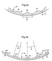
- Figs. 4 and 5 illustrate the first embodiment of the invention with Fig. 4 providing a schematic perspective illustration of a nozzle whilst Fig. 5 provides an enlarged view of a section of the nozzle bypass inner wall surface.
- Undulations or bumps 40 are regularly circumferentially distributed about an inner surface 41 of an outer wall 42 of a bypass nozzle of an engine 43.
- the effect of the undulations or bumps 40 is to provide a convergent-divergent nozzle form along the axial length of the undulation or bumps 40 with generally areas between the undulations or bumps 40 being flatter and therefore creating a convergent nozzle format.
- noise suppression is achieved through mixing of the shear layer so that the turbulence intensity is lower in the regions where the turbulence interacts with the shock structure from the nozzle.
- the shock cell repeat pattern will vary across the undulations again leading to noise suppression.
- the undulations 40 are sinusoidal and have amplitude 39 in the range 0.1 - 3.0% of the nozzle exit diameter, but preferably in the range between 0.3% and 1.5%.
- the undulations have maximum amplitude point 38 positioned within ⁇ 2% nozzle exit diameter of the nozzle throat position 4.
- the circumferential extent 26 of the undulations 40 is defined by a length equivalent to between 1° and 45° and the angular spacing 27 between maximum amplitude points 38 is between 2° and 90°, i.e. the total number of bumps is between 180 and 4, however, a preferred number of maximum amplitude points is between 12 and 45.
- bumps 40a-e alternate shapes of bumps 40a-e are shown. These alternately shaped bumps 40a-e may be either attached by suitable means to an existing smooth nozzle surface or may be machined into the nozzle wall. Where the bumps are machined into the nozzle wall they may either be proud of the wall surface 23 (as shown) or machined in as for the sinusoidal wave form having peaks 38 and troughs 49 defined by the respective inverse bump shape.
- the undulations 40 are preferably shaped in cross-section as shown by bump 40a, which comprises maximum amplitude 38 defined by a radius 24 and blend radii 25 smoothing the shape into a circumferential profile 23 of the nozzle wall 42.
- the maximum amplitude 38 is in this case the radial height above the existing or original wall surface 23.
- Figure 5b also shows alternative shapes the undulations or bumps may take without departing from the scope of the invention.
- Bump 40b is generally trapezoidal in cross-section; bump 40c is triangular; bump 40d is defined by a constant radius (part-circular) and bump 40e is an asymmetric version of bump 40a and similarly defined by three radii but radius 25' is greater than 25".
- Each bump 40a-e, in their respective array of bumps, are angularly spaced apart a corresponding distance 27 peak-to-peak (38) dependent on the number required around the nozzle's circumference.
- the spacing of the bumps peak or maximum amplitude point 38 is the total length of side divided by the number of bumps.
- the nozzle exit diameter was 58 millimetres, the first radius is at approximately 11.2 millimetres, the second is at a position 3.6 millimetres upstream of the nozzle exit plane and the final radius at the exit plane itself.
- the amplitude of the undulations or bumps is in the order of 0.8 millimetres (1.38% of the nozzle exit diameter) with an axial position of maximum amplitude as indicated at 3.6 millimetres upstream of the nozzle exit plane (6% of the nozzle diameter).
- the scale model comprised 20 bumps 40 (Fig 5a) evenly spaced at 18° intervals. A 2db noise reduction was achieved over a similar nozzle without bumps.
- the nozzle diameter is 1450 millimetres, having a bump amplitude in the order of 4.5 millimetres (0.31% of the nozzle exit diameter) with the first radius at approximately 280 millimetres upstream of the nozzle exit plane, the second radius at approximately 90 millimetres upstream of the nozzle exit plane and the third radius at the nozzle exit plane.
- This nozzle comprised 20 sinusoidal bumps 40a (Fig 5a) evenly spaced at 18° intervals.
- amplitudes and axial lengths may be used within the ranges indicated throughout this specification and depending on particular noise reduction requirements.
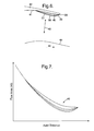
- Figs. 6 and 7 illustrate respectively a schematic cross-section through one of the undulations or bumps 40 in the inner nozzle surface 41 of an outer wall of a bypass nozzle 42 with respect to an opposed surface 44 of the nozzle (Fig. 6) and in Fig. 7 a graphic representation illustrating differences in the available nozzle flow area relative to axial distance along the bump 40.
- the available flow area 45 between the nozzle surface 41 and the opposed surface 44 is varied in the circumferential direction through the bump and the spaces in the area 41 between the bumps 40.
- This is illustrated in Fig. 7 through the representative relationship lines 46 showing the variation in available flow area 45 with axial distance in the direction 46 at different circumferential positions across one bump.
- the convergent-divergent ratio is depicted against circumferential angle across an undulation or bump without a flat space section between undulations such that there is a continuous sinusoidal variation from one bump to the next such that the convergent-divergent ratio oscillates sinusoidally around an average value 47, but it will be understood where there is an undulation of bump formed with relatively flat spaces either side then a half sinusoidal relationship will be provided in terms of the variation in convergent-divergent in ratio as the bump or undulation amplitude moves into and out of the nozzle across the circumferential width of the bump or undulation.
- the available flow area 46 will vary sinusoidally across the circumferential width of the bump or undulation and relative to a maximum exit area 48 defined at the exit plane of the nozzle.
- the angle of the flow relative to the axis of the jet in the region just behind the nozzle exit is a function of the nozzle pressure ratio. This is a result of the flow emerging from the nozzle expanding to match the conditions outside of the nozzle.
- the mass flow of the jet is fixed by the area of the nozzle throat.
- the final flow area of the jet (outside of the nozzle) is dependent on the mass flow and the freestream conditions.
- the freestream conditions are very nearly circumferentially uniform and so the flow area of the jet is proportional to the throat area these being linked by the mass flow.
- a circumferential variation in the throat area thus leads to a circumferential variation in the final flow area of the jet. This mimics the effects of serrations and produces a circumferentially non-uniform flow field.
- the circumferential variation in convergent-divergent ratio as a result of a circumferential variation in throat area thus produces a circumferentially non-uniform flow field downstream of the nozzle exit. This enhances mixing of the shear layer reducing the extent of turbulent flow. The interaction of the turbulence and the shock cell structure responsible for the shock cell noise is thus further reduced as the turbulence is reduced.
- circumferential variation of convergent-divergent ratio avoids the performance degradation due to tabs inserted into flow with incidence as this increases the drag on the serration.
- Serrations and tabs also have increased surface area exposed to the flow and this increases drag.
- the length (perimeter) of the trailing edge of the nozzle is a minimum for a circular nozzle in a plane perpendicular to the engine axis. The application of serrations or tabs increases the length of the nozzle trailing edge and thus increases the base drag.
- the mixing achieved by varying the throat area circumferentially with undulations is as a result of manipulating the shock waves rather than deflecting the flow.
- Manipulating the shock waves to change flow directions is a near lossless process unlike deflecting the flow.
- Serrations necessarily add weight to the design.
- the circular planar nozzle exit permitted by this invention is the minimum weight design. Mechanical challenge of tab and associated stress concentration are avoided. However, serration tabs suppress shock cell noise by enhanced mixing of shear layer.
- the undulations or bumps may be provided on an inner surface of the outer wall of a bypass nozzle as described above, or alternatively the bumps or undulations can be provided on the outer surface of an inner wall of the bypass nozzle or bump undulations provided on the inner surface of the outer wall of the core nozzle or bumps and undulations provided on the outer surface of the inner wall of the core nozzle or combinations of these configurations.
- bump or undulation position in relation to distribution as well as exit plane area will depend upon particular engine design requirements.
- Fig. 10 illustrates a first alternative embodiment of a nozzle in which bumps 140 are arranged with a regular distribution about an inner nozzle surface 141 of an outer wall of a bypass nozzle.
- the bumps have undisturbed regions 143 between them in which the nozzle therefore acts as a simple convergent nozzle in these parts with the bumps 140 providing the convergent-divergent variation in available flow throat area as required for noise suppression.
- an opposed surface (not shown) of the nozzle may include itself undulations or bumps which may directly oppose the bumps 140 or interleave with those bumps 140 such that these bumps in the opposed surface directly oppose the undisturbed regions 143.
- Fig. 11 illustrates a second alternative embodiment of a nozzle.
- bumps 240 are arranged with irregular spacing in an inner nozzle surface 241 of an outer wall 242 of a bypass nozzle.
- irregular spacing of the bumps 240 it is possible that there is further disturbance with respect to circumferential modes for shear layer turbulence or there may be variation in the noise suppression level at certain directions of the nozzle in comparison with others dependent upon operational requirements.
- Fig. 12 illustrates a third alternative embodiment of the present nozzle.
- bumps 340 are located in groups or individually in an inner nozzle surface 341.
- Fig. 13 illustrates a fourth alternative embodiment of the present nozzle in which undulations or bumps are provided at different axial positions as compared to circumferential conditions in previous embodiments.
- bumps 440 are provided in an inner nozzle surface 441 of an outer wall 442 of a bypass nozzle.
- undulations or bumps 440a are essentially based at an exit plane edge 443 of the nozzle, whilst bumps or undulations 440b are slightly displaced from that exit edge 443, whilst the undulations or bumps 440c are even further displaced from the edge 443.
- Such an arrangement will provide a variation in the convergent-divergent ratio over a broader axial length of the nozzle and therefore provide different operational performance compared to previous embodiments.
- each of the bumps 440a,b,c,d their first radius, which defines their upstream surface, are located at respectively 0%, 5%, 2.5% and 7.5% of the nozzle exit diameter, upstream of the nozzle throat.
- each of the bumps 440a,b,c,d are located and sized within the ranges defined hereinbefore.
- Figures 13a and 13b show alternative embodiments to that shown in Figure 13, where a number of adjacent bumps (440a,b,c,d in Figure 13) are merged circumferentially to form one or more larger and therefore more complex undulations 443, 444.
- the bumps 443, 444 are generally sinusoidal or part sinusoidal in a circumferential sense and comprise their first radii axially located between 0% and 7.5% of the nozzle exit diameter, upstream of the nozzle throat.
- the second and third cross-section radii are accordingly located relative to the first radius at any given axial cross-section through each bump 443, 444.
- the maximum amplitude is constant (i.e. it forms a ridge of maximum amplitude) except at the circumferential extents, where each bump blends out to the nozzle wall. It should be appreciated that in other embodiments the maximum amplitude may be varied circumferentially along the bumps 443, 444.
- Fig. 14 illustrates a fifth alternative embodiment of the present nozzle in which bumps 540 are provided which have different amplitudes at different circumferential and axial locations in an inner nozzle surface 541 of an outer wall 542.
- the different amplitudes for the bumps or undulations 540 may provide differing levels of noise reduction in different directions of the nozzle, and through changing the available flow area throat could improve mixing to allow further noise control.
- bump or undulations 540b have a greater amplitude than bumps or undulations 540a, 540c and have a greater axial length whilst undulations 540b, 540c respectively have different circumferential widths and axial lengths compared to each other and undulation 540a.
- Fig. 15 illustrates a sixth alternative embodiment of a nozzle in which bumps or undulations 640 are presented in an inner nozzle surface 641 of an outer wall 642 of a bypass nozzle.
- the bumps or undulations 640 are grouped in regions with other undisturbed regions between them such that differing levels of noise suppression will be provided and therefore quieter areas achieved relative to normal nozzle operation.
- Such regionalisation of the bumps or undulations will provide a similar effect to a regular spacing and the bumps or undulations described with regard to the third alternative embodiment (Fig. 12) above.
- Fig. 16 illustrates a seventh alternative embodiment of a nozzle.
- undulations or bumps 740 are presented in a serrated outer wall 742 of a bypass nozzle.
- the bumps or undulations 740 are again presented on an inner nozzle surface 741 of the wall 742.
- the bumps or undulations could be provided in an inner or outer wall of a nozzle, but Fig. 16 only illustrates provision of the bumps or undulations 740 in the inner surface 741 of the outer wall 742.
- the effects of serrations 743 are enhanced by this circumferential change in the convergent-divergent ratio created by the bumps and undulations 740.
- Such an arrangement may provide enhanced noise suppression, although as described previously, provision of serrations 743 may add to drag and other factors with respect to engine operation.
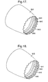
- Fig. 17 provides a further eighth alternative embodiment of the present nozzle.
- bumps or undulations 840 are provided upon an inner nozzle surface 841 of an outer wall 842 of a bypass nozzle.
- the bumps or undulations 840 circumferentially change the convergent-divergent ratio, but do not extend into tab or serration portions 843, but are upon a fixed portion of the nozzle prior to such serrations 43.
- such an approach will provide an alternative for particular operational requirements in terms of noise suppression and shear layer turbulence.
- Fig. 18 illustrates a further ninth alternative embodiment of a nozzle.
- bumps or undulations 940 are again provided in an inner nozzle surface 941 of an outer wall 942 of a bypass nozzle.
- the bumps or undulations 940 still remain prior to serrations 942 in the exit plane of the nozzle and in comparison with the embodiment depicted in Fig. 17, these bumps 940 are out of phase with the serrations 943 in order to provide a further enhancement or variation in noise suppression performance dependent upon operational requirements.
- bumps or undulations in accordance with the present invention may be variable dependent upon operational conditions or desired requirements.
- the bumps or undulations may have a shaped memory alloy type function and therefore vary according to temperature or other requirements in terms of amplitude and shape for variation in the turbulence created in the shear layer for noise suppression.
- the bumps or undulations may be arranged to be electively deployable through use of inflation or deflectable mechanical panels or otherwise in order to change their amplitude, both in terms of inward deflection as well as axial length and circumferential spacing for operational requirements.
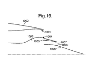
- Fig. 19 provides a schematic illustration of an engine nozzle arrangement in which the respective nozzle surfaces are illustrated.
- a bypass nozzle is provided by an outer wall 1002 and an inner wall 1003 such that surfaces 1001 and 1004 may incorporate bumps or undulations in accordance with the present invention in order to vary the convergent and divergent ratio across the nozzle surfaces 1001, 1004 in accordance with the present invention.
- an outer wall 1005 and an inner wall 1006 present opposing surfaces 1007, 1008 of a core nozzle.
- These nozzle surfaces 1007, 1008 may also incorporate undulations or bumps in accordance with the present invention in order to vary the convergent-divergent ratio across the core nozzle.
- additional noise suppression may be provided by creating turbulence in the shear layer between jets for noise suppression as described above.
- the nozzle 42 comprises an arrangement of deployable noise reducing tabs 80, 82 which are described in US6813877 , the teachings of which are incorporated herein.
- circumferentially alternate tabs 80 are rigidly fixed in a 'deployed' position as shown in the figure, where they interact with the gas streams to enhance mixing out the noise creating shear layer between gas streams.
- the deployable tabs 82 comprise shape memory material and are moveable between a deployed position as shown in Figure 20 and a non-deployed position, where they are aligned and abutting tabs 80. During take-off and climb the tabs 82 are deployed, angled radially outwardly, for noise reduction purposes and the exit area of the nozzle 12 is enlarged.
- This enlargement reduces the velocity of the gas stream issuing from the bypass duct 12 and which intrinsically reduces exhaust noise.
- the tabs 82 are in the non-deployed position, where adjacent tabs' edges 88, 90 are in sealing engagement with one another, and the exit area is therefore reduced. This reduction increases the velocity of the exhaust gas stream and improves engine efficiency.
- the exhaust exit plane 36 in this case is defined by a downstream edge 86 of the tabs 80, 82 when in their non-deployed position.
- the bumps 40 are still positioned within the range of positions specified hereinbefore and may therefore be situated on one or more of the tabs' radially inner surface, depending on the axial length of the tab and the convergent-divergent ratio.
- Figure 21 show a bump 40 situated on each of the tabs 80, 82 around the nozzle 42 circumference.
- the shape and configuration of the bumps 40 are as hereinbefore described.
- the bumps 40 are deployable and preferably comprise shape memory material as a means for actuating the bumps between a deployed position 40' and a non-deployed position 40".
- Shape memory material SMM is well known in the industry and is not discussed further except that its operation is similar to that for the deployable nozzle tabs as disclosed by the present Applicant in US6813877 , the teachings of the use of shape memory material are incorporated herein.
- the main advantage of having deployable bumps is to reduce aerodynamic drag when they are not required.
- the gas stream through the nozzle 42 is not disturbed by any bump 40 as would otherwise be the case and described hereinbefore.
- the bumps 40 interact with the gas stream and reduce exhaust noise as herein described.
- the bumps 40 are formed from a shape memory material element 60 which is prestressed to a particular shape and changes shape, at a predetermined temperature, between the deployed and non-deployed positions.
- securing means 61 attaches a continuous ring of SMM defining bump elements 60.
- individual SMM elements may equally be used and aatched to the nozzle wall by the securing means 61.
- the securing means 61 may be a nut and bolt, weld, screw or other capturing member.
- the dashed lines define the non-deployed position 40" of the SMM element 60.
- the nozzle wall 42 defines a bump 62 having amplitude between the maximum amplitude 38 and the otherwise 'original' nozzle wall profile indicated by the dashed line 63.
- This arrangement is advantageous in that there are two bump amplitudes which are help to attenuate cabin noise at two different engine operating points.
- FIG 22A shows a further embodiment of the SMM element 60, where there are two layers of SMM material 64, 65 which have different switch temperatures. At a first temperature element 64 switches and the bump obtains a first shape 40''' and at a second temperature element 65 obtains a second shape, the second shape having a greater amplitude that the first shape.
- the layer 64 is a spring element, which comprises titanium or other suitable resilient material, such that the spring element provides a force to retain or return the bump in the non-deployed position or perhaps in the deployed position.
- the element 60 is arranged such that the change in modulus of the SMM element 65 is capable of bending the element 60 into the desired shape.
Landscapes
- Engineering & Computer Science (AREA)
- Chemical & Material Sciences (AREA)
- Combustion & Propulsion (AREA)
- Mechanical Engineering (AREA)
- General Engineering & Computer Science (AREA)
- Aviation & Aerospace Engineering (AREA)
- Nozzles (AREA)
- Fuel-Injection Apparatus (AREA)
Applications Claiming Priority (1)
| Application Number | Priority Date | Filing Date | Title |
|---|---|---|---|
| GBGB0505246.9A GB0505246D0 (en) | 2005-03-15 | 2005-03-15 | Engine noise |
Publications (2)
| Publication Number | Publication Date |
|---|---|
| EP1703114A1 true EP1703114A1 (fr) | 2006-09-20 |
| EP1703114B1 EP1703114B1 (fr) | 2007-08-01 |
Family
ID=34509061
Family Applications (1)
| Application Number | Title | Priority Date | Filing Date |
|---|---|---|---|
| EP06251122A Expired - Fee Related EP1703114B1 (fr) | 2005-03-15 | 2006-03-02 | Bruit du moteur |
Country Status (4)
| Country | Link |
|---|---|
| US (1) | US7735601B1 (fr) |
| EP (1) | EP1703114B1 (fr) |
| DE (1) | DE602006000051T2 (fr) |
| GB (1) | GB0505246D0 (fr) |
Cited By (26)
| Publication number | Priority date | Publication date | Assignee | Title |
|---|---|---|---|---|
| WO2008045057A1 (fr) * | 2006-10-12 | 2008-04-17 | United Technologies Corporation | Tuyère à surface de dérivation variable, du type à vessie |
| FR2920035A1 (fr) * | 2007-08-17 | 2009-02-20 | Airbus France Sas | Turbomoteur a emission de bruit reduite pour aeronef |
| FR2921408A1 (fr) * | 2007-09-26 | 2009-03-27 | Snecma Sa | Jonc d'etancheite ou d'amortissement des vibrations pour rotor de turbomachine |
| EP2093407A2 (fr) * | 2008-02-20 | 2009-08-26 | United Technologies Corporation | Moteur à turbine à gas à tuyère de soufflante à géométrie variable par un système de vessies et procédé de variation de la géométrie d'une telle tuyère |
| WO2010019131A1 (fr) * | 2008-08-11 | 2010-02-18 | The Boeing Company | Configurations de sortie de tuyère de moteur à réaction, comprenant des saillies orientées par rapport à des pylônes, et systèmes et procédés relatifs |
| WO2010144181A1 (fr) * | 2009-06-12 | 2010-12-16 | The Boeing Company | Ensemble turbine à gaz et procédé de fonctionnement correspondant |
| EP2270312A1 (fr) * | 2009-07-01 | 2011-01-05 | PEM-Energy Oy | Construction aréo- ou hydrodynamique |
| US7870722B2 (en) | 2006-12-06 | 2011-01-18 | The Boeing Company | Systems and methods for passively directing aircraft engine nozzle flows |
| EP1995441A3 (fr) * | 2007-05-21 | 2011-03-09 | General Electric Company | Tuyère d'échappement à chevrons cannelés |
| US7966826B2 (en) | 2007-02-14 | 2011-06-28 | The Boeing Company | Systems and methods for reducing noise from jet engine exhaust |
| US7966824B2 (en) | 2006-08-09 | 2011-06-28 | The Boeing Company | Jet engine nozzle exit configurations and associated systems and methods |
| WO2012010124A1 (fr) * | 2010-06-24 | 2012-01-26 | Eads Deutschland Gmbh | Dispositif de réduction du bruit d'un réacteur |
| GB2474377B (en) * | 2008-06-26 | 2012-02-29 | Gen Electric | Duplex tab exhaust nozzle |
| US8157207B2 (en) | 2006-08-09 | 2012-04-17 | The Boeing Company | Jet engine nozzle exit configurations, including projections oriented relative to pylons, and associated systems and methods |
| CN102472201A (zh) * | 2009-08-06 | 2012-05-23 | 波音公司 | 高刚度形状记忆合金驱动的飞机结构 |
| FR2986832A1 (fr) * | 2012-02-10 | 2013-08-16 | Snecma | Procede pour definir la forme d'une tuyere convergente-divergente d'une turbomachine et tuyere convergente-divergente correspondante. |
| CN103835810A (zh) * | 2012-11-27 | 2014-06-04 | 中航商用航空发动机有限责任公司 | 一种航空发动机进气短舱的声衬装置及航空发动机 |
| US20140202164A1 (en) * | 2009-06-12 | 2014-07-24 | David F. Cerra | Gas turbine engine nozzle including housing having scalloped root regions |
| FR3010454A1 (fr) * | 2013-09-10 | 2015-03-13 | Snecma | Arriere corps de turboreacteur a flux melanges comportant un melangeur a lobes et des chevrons a surface interne non axisymetrique |
| EP2865874A3 (fr) * | 2013-10-24 | 2015-08-05 | The Boeing Company | Procédés et appareil de vectorisation passive de poussée et déflexion de panache |
| EP3001019A1 (fr) * | 2014-09-25 | 2016-03-30 | The Boeing Company | Procédés et appareil de vectorisation passive de poussée et déflexion de panache |
| US9732700B2 (en) | 2013-10-24 | 2017-08-15 | The Boeing Company | Methods and apparatus for passive thrust vectoring and plume deflection |
| EP3358173A1 (fr) * | 2017-02-02 | 2018-08-08 | Rolls-Royce plc | Corps arrière de capot central |
| RU2767862C2 (ru) * | 2017-08-21 | 2022-03-22 | Сафран Эркрафт Энджинз | Модифицированное звуковое вторичное сопло |
| CN116674758A (zh) * | 2022-04-28 | 2023-09-01 | 中国航发沈阳发动机研究所 | 一种非接触式飞发搭接结构设计方法 |
| CN116674758B (zh) * | 2022-04-28 | 2024-05-24 | 中国航发沈阳发动机研究所 | 一种非接触式飞发搭接结构设计方法 |
Families Citing this family (45)
| Publication number | Priority date | Publication date | Assignee | Title |
|---|---|---|---|---|
| US9328695B2 (en) * | 2006-10-12 | 2016-05-03 | United Technologies Corporation | Variable fan nozzle using shape memory material |
| US7797944B2 (en) | 2006-10-20 | 2010-09-21 | United Technologies Corporation | Gas turbine engine having slim-line nacelle |
| US7870721B2 (en) * | 2006-11-10 | 2011-01-18 | United Technologies Corporation | Gas turbine engine providing simulated boundary layer thickness increase |
| US8727267B2 (en) * | 2007-05-18 | 2014-05-20 | United Technologies Corporation | Variable contraction ratio nacelle assembly for a gas turbine engine |
| JP4699487B2 (ja) * | 2007-05-25 | 2011-06-08 | 三菱重工業株式会社 | 高揚力発生装置、翼および高揚力発生装置の騒音低減構造 |
| US8402739B2 (en) * | 2007-06-28 | 2013-03-26 | United Technologies Corporation | Variable shape inlet section for a nacelle assembly of a gas turbine engine |
| US9228534B2 (en) | 2007-07-02 | 2016-01-05 | United Technologies Corporation | Variable contour nacelle assembly for a gas turbine engine |
| FR2921977B1 (fr) * | 2007-10-08 | 2012-09-21 | Airbus France | Turbomoteur a double flux pour aeronef |
| US9004399B2 (en) | 2007-11-13 | 2015-04-14 | United Technologies Corporation | Nacelle flow assembly |
| US8186942B2 (en) * | 2007-12-14 | 2012-05-29 | United Technologies Corporation | Nacelle assembly with turbulators |
| US7954754B2 (en) * | 2008-06-02 | 2011-06-07 | The United States Of America As Represented By The Secretary Of The Army | Mechanical acoustic noise generator system for scramjet engine |
| FR2934875B1 (fr) * | 2008-08-06 | 2010-08-13 | Aircelle Sa | Nacelle de turboreacteur a chevrons mobiles. |
| GB0907513D0 (en) * | 2009-05-01 | 2009-06-10 | Rolls Royce Plc | A flow modulating device |
| US9671797B2 (en) | 2009-05-08 | 2017-06-06 | Gas Turbine Efficiency Sweden Ab | Optimization of gas turbine combustion systems low load performance on simple cycle and heat recovery steam generator applications |
| US9267443B2 (en) | 2009-05-08 | 2016-02-23 | Gas Turbine Efficiency Sweden Ab | Automated tuning of gas turbine combustion systems |
| US9354618B2 (en) | 2009-05-08 | 2016-05-31 | Gas Turbine Efficiency Sweden Ab | Automated tuning of multiple fuel gas turbine combustion systems |
| US8437941B2 (en) | 2009-05-08 | 2013-05-07 | Gas Turbine Efficiency Sweden Ab | Automated tuning of gas turbine combustion systems |
| US8337160B2 (en) * | 2009-10-19 | 2012-12-25 | Toyota Motor Engineering & Manufacturing North America, Inc. | High efficiency turbine system |
| US9528468B2 (en) * | 2009-10-28 | 2016-12-27 | Ihi Corporation | Noise reduction system |
| US9242720B2 (en) * | 2010-10-21 | 2016-01-26 | The United States Of America As Represented By The Administrator Of The National Aeronautics And Space Administration | Autonomous slat-cove-filler device for reduction of aeroacoustic noise associated with aircraft systems |
| FR2972224B1 (fr) * | 2011-03-04 | 2018-04-20 | Safran Aircraft Engines | Tuyere avec noyau aval presentant une forte courbure |
| US9447970B2 (en) * | 2011-05-12 | 2016-09-20 | General Electric Company | Combustor casing for combustion dynamics mitigation |
| US9429071B2 (en) * | 2011-06-23 | 2016-08-30 | Continuum Dynamics, Inc. | Supersonic engine inlet diffuser with deployable vortex generators |
| US9109466B2 (en) * | 2011-07-22 | 2015-08-18 | The Board Of Trustees Of The Leland Stanford Junior University | Diffuser with backward facing step having varying step height |
| US8573354B1 (en) * | 2011-12-06 | 2013-11-05 | The Boeing Company | Noise suppression system for hollow vehicle fasteners |
| US9416752B2 (en) | 2012-02-28 | 2016-08-16 | Pratt & Whitney Canada Corp. | Gas turbine exhaust having reduced jet noise |
| US9587632B2 (en) * | 2012-03-30 | 2017-03-07 | General Electric Company | Thermally-controlled component and thermal control process |
| US20130255796A1 (en) * | 2012-03-30 | 2013-10-03 | General Electric Company | Flow-control device, component having a flow-control device, and method of producing a flow-control device |
| US20140083079A1 (en) * | 2012-09-26 | 2014-03-27 | United Technologies Corporation | Geared turbofan primary and secondary nozzle integration geometry |
| DE102012219541A1 (de) * | 2012-10-25 | 2014-04-30 | Deutsches Zentrum für Luft- und Raumfahrt e.V. | Düse, Strukturelement und Verfahren zur Herstellung einer Düse |
| US9989009B2 (en) * | 2012-10-31 | 2018-06-05 | The Boeing Company | Methods and apparatus for sealing variable area fan nozzles of jet engines |
| US9145801B2 (en) * | 2013-07-01 | 2015-09-29 | The Boeing Company | Systems and methods for acoustic resonance mitigation |
| EP2837795B1 (fr) | 2013-08-14 | 2019-05-01 | Ansaldo Energia IP UK Limited | Agencement d'admission amélioré dans une centrale électrique à turbine à gaz |
| US10550704B2 (en) | 2013-08-23 | 2020-02-04 | United Technologies Corporation | High performance convergent divergent nozzle |
| US9869190B2 (en) | 2014-05-30 | 2018-01-16 | General Electric Company | Variable-pitch rotor with remote counterweights |
| US10072510B2 (en) | 2014-11-21 | 2018-09-11 | General Electric Company | Variable pitch fan for gas turbine engine and method of assembling the same |
| FR3041375B1 (fr) * | 2015-09-22 | 2020-01-17 | Safran Aircraft Engines | Ensemble de circulation d'un flux d'un turboreacteur d'un aeronef |
| US10100653B2 (en) | 2015-10-08 | 2018-10-16 | General Electric Company | Variable pitch fan blade retention system |
| DE102017104078A1 (de) | 2017-02-27 | 2018-08-30 | Rolls-Royce Deutschland Ltd & Co Kg | Strahltriebwerk mit einer radial variablen Wandung |
| FR3095675B1 (fr) * | 2019-05-03 | 2021-04-09 | Safran Aircraft Engines | Mélangeur à flux séparés de turbomachine |
| CN110410230B (zh) * | 2019-08-07 | 2020-09-25 | 北京航空航天大学 | 一种变循环发动机中的鳞片式整体变形后涵道引射器 |
| CN110448772B (zh) * | 2019-09-20 | 2021-09-14 | 成都市第二人民医院 | 基于呼吸科用的深入精准给药装置及给药方法 |
| US11674435B2 (en) | 2021-06-29 | 2023-06-13 | General Electric Company | Levered counterweight feathering system |
| US11795964B2 (en) | 2021-07-16 | 2023-10-24 | General Electric Company | Levered counterweight feathering system |
| CN117846807A (zh) * | 2024-03-07 | 2024-04-09 | 中国空气动力研究与发展中心高速空气动力研究所 | 一种组合式超声速喷流降噪喷管 |
Citations (8)
| Publication number | Priority date | Publication date | Assignee | Title |
|---|---|---|---|---|
| GB1193372A (en) * | 1967-01-18 | 1970-05-28 | Snecma | A Silencer for Jet Systems |
| US3592291A (en) * | 1969-11-17 | 1971-07-13 | Rohr Corp | Method and apparatus for suppressing the noise and augmenting the thrust of a jet engine |
| US3611724A (en) * | 1970-01-07 | 1971-10-12 | Gen Electric | Choked inlet noise suppression device for a turbofan engine |
| US3780827A (en) * | 1972-12-19 | 1973-12-25 | Nasa | Gas turbine exhaust nozzle |
| EP0999358A2 (fr) * | 1998-11-06 | 2000-05-10 | United Technologies Corporation | Dispositif d'amortisation du bruit du jet chez un réacteur |
| US6082635A (en) * | 1996-06-12 | 2000-07-04 | The United States Of America As Represented By The Administrator Of The National Aeronautics And Space Administration | Undulated nozzle for enhanced exit area mixing |
| US6813877B2 (en) | 2001-03-03 | 2004-11-09 | Rolls-Royce Plc | Gas turbine engine exhaust nozzle having a noise attenuation device driven by shape memory material actuators |
| EP1482159A2 (fr) * | 2003-05-31 | 2004-12-01 | Rolls-Royce Plc | Tuyère et moteur avec une telle tuyère |
Family Cites Families (43)
| Publication number | Priority date | Publication date | Assignee | Title |
|---|---|---|---|---|
| US2944623A (en) * | 1955-09-02 | 1960-07-12 | Jr Albert G Bodine | Jet engine noise reducer |
| US3065818A (en) * | 1957-09-14 | 1962-11-27 | Rolls Royce | Jet noise suppressor nozzle |
| US3174282A (en) * | 1963-04-19 | 1965-03-23 | Ryan Aeronautical Co | Asymmetrical jet nozzle noise suppressor |
| GB1045295A (en) | 1964-03-25 | 1966-10-12 | Peter Bradshaw | Improvements in or relating to a jet noise suppression device |
| US3919627A (en) | 1970-08-06 | 1975-11-11 | Gerald F Allen | Conductivity measuring method and apparatus utilizing coaxial electrode cells |
| US3776363A (en) * | 1971-05-10 | 1973-12-04 | A Kuethe | Control of noise and instabilities in jet engines, compressors, turbines, heat exchangers and the like |
| US3905445A (en) * | 1972-01-12 | 1975-09-16 | Bolt Beranek & Newman | Vortex turbulence noise generation suppressor |
| US3861140A (en) * | 1972-07-05 | 1975-01-21 | Gen Electric | Turbofan engine mixer |
| US3814901A (en) | 1973-05-07 | 1974-06-04 | Lincoln Mfg Co | Steam heating device |
| US3934675A (en) * | 1974-05-20 | 1976-01-27 | Lear Avia Corporation | Jet engine noise suppressor |
| US4372110A (en) * | 1976-02-13 | 1983-02-08 | Nasa | Noise suppressor for turbo fan jet engines |
| US4135363A (en) * | 1976-05-13 | 1979-01-23 | United Technologies Corporation | Device to provide flow inversion in a turbofan exhaust tailpipe to achieve low jet noise |
| US4117671A (en) * | 1976-12-30 | 1978-10-03 | The Boeing Company | Noise suppressing exhaust mixer assembly for ducted-fan, turbojet engine |
| GB2012881B (en) | 1977-12-24 | 1982-03-24 | British Aircraft Corp Ltd | Jet propulsion efflux outlets |
| US4496906A (en) | 1981-10-28 | 1985-01-29 | Clack Corporation | Liquid conductivity monitor |
| GB2132269B (en) | 1982-12-03 | 1986-07-30 | Secr Defence | Silencer for high velocity gas flow |
| CA1324999C (fr) * | 1986-04-30 | 1993-12-07 | Walter M. Presz, Jr. | Elements a surfaces offrant une faible resistance au frottement |
| US4754924A (en) * | 1987-04-03 | 1988-07-05 | Shannon Aubrey J | Variable geometry nozzle |
| US4806912A (en) | 1987-06-19 | 1989-02-21 | Clack Robert A | Monitoring system for a liquid purification system |
| US5154052A (en) * | 1990-05-07 | 1992-10-13 | General Electric Company | Exhaust assembly for a high speed civil transport aircraft engine |
| FR2685386B1 (fr) * | 1991-12-20 | 1994-03-25 | Propulsion Ste Europeenne | Systeme d'amortissement des instabilites de combustion haute frequence dans une chambre de combustion. |
| US5178125A (en) | 1992-01-30 | 1993-01-12 | Hui-Ling Chiu | Multifunctional water boiling and steam warming device |
| GB2289921A (en) | 1994-06-03 | 1995-12-06 | A E Harris Limited | Nozzle for turbofan aeroengines |
| US6094907A (en) * | 1996-06-05 | 2000-08-01 | The Boeing Company | Jet engine and method for reducing jet engine noise by reducing nacelle boundary layer thickness |
| US6078178A (en) | 1998-11-23 | 2000-06-20 | U.S. Filter Corporation | Water quality indicating apparatus having self-cleaning test probes |
| AU2404000A (en) * | 1999-01-04 | 2000-07-24 | Allison Advanced Development Company | Exhaust mixer and apparatus using same |
| US6666016B2 (en) * | 1999-01-31 | 2003-12-23 | The Regents Of The University Of California | Mixing enhancement using axial flow |
| JP2001271710A (ja) * | 2000-03-24 | 2001-10-05 | Ishikawajima Harima Heavy Ind Co Ltd | ジェットエンジン用騒音低減装置及び排気ノズル |
| US6285110B1 (en) * | 2000-04-17 | 2001-09-04 | General Electric Co. | Spline retaining ring |
| US7065957B2 (en) * | 2000-05-05 | 2006-06-27 | The Boeing Company | Segmented mixing device for jet engines and aircraft |
| US6505706B2 (en) * | 2001-06-14 | 2003-01-14 | Pratt & Whitney Canada Corp. | Exhaust flow guide for jet noise reduction |
| ATE358772T1 (de) * | 2001-12-07 | 2007-04-15 | Jack H Anderson | Blütenmischer für strahltriebwerke |
| BR0307845B1 (pt) * | 2002-02-22 | 2012-09-18 | bocal de exaustão de misturador duplex. | |
| US6658839B2 (en) * | 2002-02-28 | 2003-12-09 | The Boeing Company | Convergent/divergent segmented exhaust nozzle |
| US6718752B2 (en) * | 2002-05-29 | 2004-04-13 | The Boeing Company | Deployable segmented exhaust nozzle for a jet engine |
| FR2855558B1 (fr) * | 2003-05-28 | 2005-07-15 | Snecma Moteurs | Tuyere de turbomachine a reduction de bruit |
| US7043898B2 (en) * | 2003-06-23 | 2006-05-16 | Pratt & Whitney Canada Corp. | Combined exhaust duct and mixer for a gas turbine engine |
| US7246481B2 (en) * | 2004-03-26 | 2007-07-24 | General Electric Company | Methods and apparatus for operating gas turbine engines |
| US7412832B2 (en) * | 2004-03-26 | 2008-08-19 | General Electric Company | Method and apparatus for operating gas turbine engines |
| FR2873166B1 (fr) * | 2004-07-13 | 2008-10-31 | Snecma Moteurs Sa | Tuyere de turbomachine a motifs a reduction de bruit de jet |
| US7389635B2 (en) * | 2004-12-01 | 2008-06-24 | Honeywell International Inc. | Twisted mixer with open center body |
| US7543452B2 (en) * | 2005-08-10 | 2009-06-09 | United Technologies Corporation | Serrated nozzle trailing edge for exhaust noise suppression |
| GB0606823D0 (en) * | 2006-04-05 | 2006-05-17 | Rolls Royce Plc | Adjustment assembly |
-
2005
- 2005-03-15 GB GBGB0505246.9A patent/GB0505246D0/en not_active Ceased
-
2006
- 2006-03-02 EP EP06251122A patent/EP1703114B1/fr not_active Expired - Fee Related
- 2006-03-02 DE DE602006000051T patent/DE602006000051T2/de active Active
- 2006-03-03 US US11/366,747 patent/US7735601B1/en not_active Expired - Fee Related
Patent Citations (8)
| Publication number | Priority date | Publication date | Assignee | Title |
|---|---|---|---|---|
| GB1193372A (en) * | 1967-01-18 | 1970-05-28 | Snecma | A Silencer for Jet Systems |
| US3592291A (en) * | 1969-11-17 | 1971-07-13 | Rohr Corp | Method and apparatus for suppressing the noise and augmenting the thrust of a jet engine |
| US3611724A (en) * | 1970-01-07 | 1971-10-12 | Gen Electric | Choked inlet noise suppression device for a turbofan engine |
| US3780827A (en) * | 1972-12-19 | 1973-12-25 | Nasa | Gas turbine exhaust nozzle |
| US6082635A (en) * | 1996-06-12 | 2000-07-04 | The United States Of America As Represented By The Administrator Of The National Aeronautics And Space Administration | Undulated nozzle for enhanced exit area mixing |
| EP0999358A2 (fr) * | 1998-11-06 | 2000-05-10 | United Technologies Corporation | Dispositif d'amortisation du bruit du jet chez un réacteur |
| US6813877B2 (en) | 2001-03-03 | 2004-11-09 | Rolls-Royce Plc | Gas turbine engine exhaust nozzle having a noise attenuation device driven by shape memory material actuators |
| EP1482159A2 (fr) * | 2003-05-31 | 2004-12-01 | Rolls-Royce Plc | Tuyère et moteur avec une telle tuyère |
Non-Patent Citations (2)
| Title |
|---|
| HARPER-BOURNE, M.; FISHER, M.J.: "The Noise from Shock Waves in Supersonic Jets", PROCEEDINGS (NO. 131) OF THE AGARD CONFERENCE ON NOISE MECHANISMS, 1973 |
| TAM, C.K.W.; TANNA, H.K., JOURNAL OF SOUND AND VIBRATION, vol. 81, no. 3, 1982, pages 337 - 358 |
Cited By (49)
| Publication number | Priority date | Publication date | Assignee | Title |
|---|---|---|---|---|
| US8157207B2 (en) | 2006-08-09 | 2012-04-17 | The Boeing Company | Jet engine nozzle exit configurations, including projections oriented relative to pylons, and associated systems and methods |
| US7966824B2 (en) | 2006-08-09 | 2011-06-28 | The Boeing Company | Jet engine nozzle exit configurations and associated systems and methods |
| US8511090B2 (en) | 2006-08-09 | 2013-08-20 | The Boeing Company | Jet engine nozzle exit configurations and associated systems and methods |
| US8276364B2 (en) | 2006-10-12 | 2012-10-02 | United Technologies Corporation | Bladder type variable area fan nozzle |
| WO2008045057A1 (fr) * | 2006-10-12 | 2008-04-17 | United Technologies Corporation | Tuyère à surface de dérivation variable, du type à vessie |
| US8166768B2 (en) | 2006-12-06 | 2012-05-01 | The Boeing Company | Systems and methods for passively directing aircraft engine nozzle flows |
| US7870722B2 (en) | 2006-12-06 | 2011-01-18 | The Boeing Company | Systems and methods for passively directing aircraft engine nozzle flows |
| US7966826B2 (en) | 2007-02-14 | 2011-06-28 | The Boeing Company | Systems and methods for reducing noise from jet engine exhaust |
| EP1995441A3 (fr) * | 2007-05-21 | 2011-03-09 | General Electric Company | Tuyère d'échappement à chevrons cannelés |
| US7963099B2 (en) | 2007-05-21 | 2011-06-21 | General Electric Company | Fluted chevron exhaust nozzle |
| CN101970843B (zh) * | 2007-08-17 | 2013-12-25 | 空中客车运营简化股份公司 | 用于飞行器的发出减少噪音的涡轮发动机 |
| CN101970843A (zh) * | 2007-08-17 | 2011-02-09 | 空中巴士营运公司 | 用于飞行器的发出减少噪音的涡轮发动机 |
| US8544278B2 (en) | 2007-08-17 | 2013-10-01 | Airbus Operations (Sas) | Turboshaft engine with reduced noise emission for aircraft |
| JP2010537098A (ja) * | 2007-08-17 | 2010-12-02 | エアバス オペレーションズ (エスアーエス) | 噴射騒音が軽減される航空機用ターボシャフト・エンジン |
| RU2451814C2 (ru) * | 2007-08-17 | 2012-05-27 | Эрбюс Операсьон (Сас) | Турбореактивный двигатель с пониженным испусканием шума для летательного аппарата |
| WO2009053555A1 (fr) * | 2007-08-17 | 2009-04-30 | Airbus France | Turbomoteur à émission de bruit réduite pour aéronef |
| FR2920035A1 (fr) * | 2007-08-17 | 2009-02-20 | Airbus France Sas | Turbomoteur a emission de bruit reduite pour aeronef |
| FR2921408A1 (fr) * | 2007-09-26 | 2009-03-27 | Snecma Sa | Jonc d'etancheite ou d'amortissement des vibrations pour rotor de turbomachine |
| EP2093407A2 (fr) * | 2008-02-20 | 2009-08-26 | United Technologies Corporation | Moteur à turbine à gas à tuyère de soufflante à géométrie variable par un système de vessies et procédé de variation de la géométrie d'une telle tuyère |
| US9010126B2 (en) | 2008-02-20 | 2015-04-21 | United Technologies Corporation | Gas turbine engine with variable area fan nozzle bladder system |
| EP2093407A3 (fr) * | 2008-02-20 | 2012-04-25 | United Technologies Corporation | Moteur à turbine à gas à tuyère de soufflante à géométrie variable par un système de vessies et procédé de variation de la géométrie d'une telle tuyère |
| GB2474377B (en) * | 2008-06-26 | 2012-02-29 | Gen Electric | Duplex tab exhaust nozzle |
| WO2010019131A1 (fr) * | 2008-08-11 | 2010-02-18 | The Boeing Company | Configurations de sortie de tuyère de moteur à réaction, comprenant des saillies orientées par rapport à des pylônes, et systèmes et procédés relatifs |
| US8356468B2 (en) | 2009-06-12 | 2013-01-22 | The Boeing Company | Gas turbine engine nozzle configurations |
| WO2010144181A1 (fr) * | 2009-06-12 | 2010-12-16 | The Boeing Company | Ensemble turbine à gaz et procédé de fonctionnement correspondant |
| US20140202164A1 (en) * | 2009-06-12 | 2014-07-24 | David F. Cerra | Gas turbine engine nozzle including housing having scalloped root regions |
| US9964070B2 (en) * | 2009-06-12 | 2018-05-08 | The Boeing Company | Gas turbine engine nozzle including housing having scalloped root regions |
| EP2270312A1 (fr) * | 2009-07-01 | 2011-01-05 | PEM-Energy Oy | Construction aréo- ou hydrodynamique |
| CN102472201A (zh) * | 2009-08-06 | 2012-05-23 | 波音公司 | 高刚度形状记忆合金驱动的飞机结构 |
| US10202939B2 (en) | 2009-08-06 | 2019-02-12 | The Boeing Company | High stiffness shape memory alloy actuated aerostructure |
| CN102472201B (zh) * | 2009-08-06 | 2014-09-17 | 波音公司 | 高刚度形状记忆合金驱动的飞机结构 |
| WO2012010124A1 (fr) * | 2010-06-24 | 2012-01-26 | Eads Deutschland Gmbh | Dispositif de réduction du bruit d'un réacteur |
| FR2986832A1 (fr) * | 2012-02-10 | 2013-08-16 | Snecma | Procede pour definir la forme d'une tuyere convergente-divergente d'une turbomachine et tuyere convergente-divergente correspondante. |
| CN103835810B (zh) * | 2012-11-27 | 2017-02-08 | 中航商用航空发动机有限责任公司 | 一种航空发动机进气短舱的声衬装置及航空发动机 |
| CN103835810A (zh) * | 2012-11-27 | 2014-06-04 | 中航商用航空发动机有限责任公司 | 一种航空发动机进气短舱的声衬装置及航空发动机 |
| FR3010454A1 (fr) * | 2013-09-10 | 2015-03-13 | Snecma | Arriere corps de turboreacteur a flux melanges comportant un melangeur a lobes et des chevrons a surface interne non axisymetrique |
| GB2532398A (en) * | 2013-09-10 | 2016-05-18 | Snecma | Afterbody for a mixed-flow turbojet engine comprising a lobed mixer and chevrons with a non-axisymmetric inner surface |
| GB2532398B (en) * | 2013-09-10 | 2021-06-23 | Snecma | Afterbody for a mixed-flow turbojet engine comprising a lobed mixer and chevrons with a non-axisymmetric inner surface |
| WO2015036684A1 (fr) * | 2013-09-10 | 2015-03-19 | Snecma | Arrière corps de turboréacteur à flux mélangés comportant un mélangeur à lobes et des chevrons à surface interne non axisymétrique |
| EP2865874A3 (fr) * | 2013-10-24 | 2015-08-05 | The Boeing Company | Procédés et appareil de vectorisation passive de poussée et déflexion de panache |
| US9546618B2 (en) | 2013-10-24 | 2017-01-17 | The Boeing Company | Methods and apparatus for passive thrust vectoring and plume deflection |
| US9732700B2 (en) | 2013-10-24 | 2017-08-15 | The Boeing Company | Methods and apparatus for passive thrust vectoring and plume deflection |
| EP3001019A1 (fr) * | 2014-09-25 | 2016-03-30 | The Boeing Company | Procédés et appareil de vectorisation passive de poussée et déflexion de panache |
| CN105464838B (zh) * | 2014-09-25 | 2019-05-21 | 波音公司 | 用于被动推力导向和羽流偏转的方法和装置 |
| CN105464838A (zh) * | 2014-09-25 | 2016-04-06 | 波音公司 | 用于被动推力导向和羽流偏转的方法和装置 |
| EP3358173A1 (fr) * | 2017-02-02 | 2018-08-08 | Rolls-Royce plc | Corps arrière de capot central |
| RU2767862C2 (ru) * | 2017-08-21 | 2022-03-22 | Сафран Эркрафт Энджинз | Модифицированное звуковое вторичное сопло |
| CN116674758A (zh) * | 2022-04-28 | 2023-09-01 | 中国航发沈阳发动机研究所 | 一种非接触式飞发搭接结构设计方法 |
| CN116674758B (zh) * | 2022-04-28 | 2024-05-24 | 中国航发沈阳发动机研究所 | 一种非接触式飞发搭接结构设计方法 |
Also Published As
| Publication number | Publication date |
|---|---|
| US20100170261A1 (en) | 2010-07-08 |
| DE602006000051D1 (de) | 2007-09-13 |
| DE602006000051T2 (de) | 2007-11-22 |
| US7735601B1 (en) | 2010-06-15 |
| EP1703114B1 (fr) | 2007-08-01 |
| GB0505246D0 (en) | 2005-04-20 |
Similar Documents
| Publication | Publication Date | Title |
|---|---|---|
| EP1703114B1 (fr) | Bruit du moteur | |
| JP5492199B2 (ja) | 双対タブ排気ノズル | |
| EP1191214B1 (fr) | Tuyère d'échappement avec aubes coupées | |
| EP1464822B1 (fr) | Méthode et appareil pour le fonctionnement d'une turbine à gaz | |
| US6532729B2 (en) | Shelf truncated chevron exhaust nozzle for reduction of exhaust noise and infrared (IR) signature | |
| US7966824B2 (en) | Jet engine nozzle exit configurations and associated systems and methods | |
| US6813877B2 (en) | Gas turbine engine exhaust nozzle having a noise attenuation device driven by shape memory material actuators | |
| EP0913567B1 (fr) | Tuyère chevronnée | |
| EP1482160B1 (fr) | Tuyère de turbomachine à réduction de bruit | |
| US20090071164A1 (en) | Fluted chevron exhaust nozzle | |
| JP2007046598A (ja) | ノズル及びガスタービンエンジン | |
| US7310939B2 (en) | Device for reducing the jet noise of a turbomachine | |
| US8307659B2 (en) | Nozzle with guiding elements | |
| US8997454B2 (en) | Turbofan engine noise suppression using fan flow deflector | |
| US20120014776A1 (en) | Method and apparatus for enhancing compressor performance | |
| US20030231777A1 (en) | High frequency jet nozzle actuators for jet noise reduction | |
| RU2148529C1 (ru) | Концевой генератор вихря для аэродинамической несущей поверхности | |
| WO2011125248A1 (fr) | Tuyère à jet plein et turboréacteur |
Legal Events
| Date | Code | Title | Description |
|---|---|---|---|
| PUAI | Public reference made under article 153(3) epc to a published international application that has entered the european phase |
Free format text: ORIGINAL CODE: 0009012 |
|
| 17P | Request for examination filed |
Effective date: 20060728 |
|
| AK | Designated contracting states |
Kind code of ref document: A1 Designated state(s): AT BE BG CH CY CZ DE DK EE ES FI FR GB GR HU IE IS IT LI LT LU LV MC NL PL PT RO SE SI SK TR |
|
| AX | Request for extension of the european patent |
Extension state: AL BA HR MK YU |
|
| 17Q | First examination report despatched |
Effective date: 20061027 |
|
| GRAP | Despatch of communication of intention to grant a patent |
Free format text: ORIGINAL CODE: EPIDOSNIGR1 |
|
| RIN1 | Information on inventor provided before grant (corrected) |
Inventor name: STIEGER, RORY DOUGLAS |
|
| AKX | Designation fees paid |
Designated state(s): DE FR GB |
|
| GRAS | Grant fee paid |
Free format text: ORIGINAL CODE: EPIDOSNIGR3 |
|
| GRAA | (expected) grant |
Free format text: ORIGINAL CODE: 0009210 |
|
| AK | Designated contracting states |
Kind code of ref document: B1 Designated state(s): DE FR GB |
|
| REG | Reference to a national code |
Ref country code: GB Ref legal event code: FG4D |
|
| RIN2 | Information on inventor provided after grant (corrected) |
Inventor name: STIEGER, RORY DOUGLAS Inventor name: STRANGE, PAUL JONATHAN RAILTON Inventor name: BRITCHFORD, KEVIN MARK |
|
| REF | Corresponds to: |
Ref document number: 602006000051 Country of ref document: DE Date of ref document: 20070913 Kind code of ref document: P |
|
| ET | Fr: translation filed | ||
| PLBE | No opposition filed within time limit |
Free format text: ORIGINAL CODE: 0009261 |
|
| STAA | Information on the status of an ep patent application or granted ep patent |
Free format text: STATUS: NO OPPOSITION FILED WITHIN TIME LIMIT |
|
| 26N | No opposition filed |
Effective date: 20080506 |
|
| REG | Reference to a national code |
Ref country code: FR Ref legal event code: PLFP Year of fee payment: 10 |
|
| REG | Reference to a national code |
Ref country code: FR Ref legal event code: PLFP Year of fee payment: 11 |
|
| REG | Reference to a national code |
Ref country code: FR Ref legal event code: PLFP Year of fee payment: 12 |
|
| REG | Reference to a national code |
Ref country code: FR Ref legal event code: PLFP Year of fee payment: 13 |
|
| PGFP | Annual fee paid to national office [announced via postgrant information from national office to epo] |
Ref country code: DE Payment date: 20200327 Year of fee payment: 15 Ref country code: GB Payment date: 20200327 Year of fee payment: 15 |
|
| PGFP | Annual fee paid to national office [announced via postgrant information from national office to epo] |
Ref country code: FR Payment date: 20200325 Year of fee payment: 15 |
|
| REG | Reference to a national code |
Ref country code: DE Ref legal event code: R119 Ref document number: 602006000051 Country of ref document: DE |
|
| GBPC | Gb: european patent ceased through non-payment of renewal fee |
Effective date: 20210302 |
|
| PG25 | Lapsed in a contracting state [announced via postgrant information from national office to epo] |
Ref country code: DE Free format text: LAPSE BECAUSE OF NON-PAYMENT OF DUE FEES Effective date: 20211001 Ref country code: FR Free format text: LAPSE BECAUSE OF NON-PAYMENT OF DUE FEES Effective date: 20210331 Ref country code: GB Free format text: LAPSE BECAUSE OF NON-PAYMENT OF DUE FEES Effective date: 20210302 |