EP1702340B1 - Zerstörungsfreies verfahren zur kontrolle eines kernreaktorelements - Google Patents
Zerstörungsfreies verfahren zur kontrolle eines kernreaktorelements Download PDFInfo
- Publication number
- EP1702340B1 EP1702340B1 EP04805436.5A EP04805436A EP1702340B1 EP 1702340 B1 EP1702340 B1 EP 1702340B1 EP 04805436 A EP04805436 A EP 04805436A EP 1702340 B1 EP1702340 B1 EP 1702340B1
- Authority
- EP
- European Patent Office
- Prior art keywords
- image
- sub
- defect
- detected
- images
- Prior art date
- Legal status (The legal status is an assumption and is not a legal conclusion. Google has not performed a legal analysis and makes no representation as to the accuracy of the status listed.)
- Expired - Lifetime
Links
- 0 CCCCCCCCS(CC)(CC(C(*)C(*)**CC)N=O)*C Chemical compound CCCCCCCCS(CC)(CC(C(*)C(*)**CC)N=O)*C 0.000 description 3
Images









Classifications
-
- G—PHYSICS
- G06—COMPUTING OR CALCULATING; COUNTING
- G06T—IMAGE DATA PROCESSING OR GENERATION, IN GENERAL
- G06T7/00—Image analysis
- G06T7/0002—Inspection of images, e.g. flaw detection
- G06T7/0004—Industrial image inspection
-
- G—PHYSICS
- G01—MEASURING; TESTING
- G01N—INVESTIGATING OR ANALYSING MATERIALS BY DETERMINING THEIR CHEMICAL OR PHYSICAL PROPERTIES
- G01N21/00—Investigating or analysing materials by the use of optical means, i.e. using sub-millimetre waves, infrared, visible or ultraviolet light
- G01N21/84—Systems specially adapted for particular applications
- G01N21/88—Investigating the presence of flaws or contamination
- G01N21/95—Investigating the presence of flaws or contamination characterised by the material or shape of the object to be examined
- G01N21/952—Inspecting the exterior surface of cylindrical bodies or wires
-
- G—PHYSICS
- G01—MEASURING; TESTING
- G01N—INVESTIGATING OR ANALYSING MATERIALS BY DETERMINING THEIR CHEMICAL OR PHYSICAL PROPERTIES
- G01N23/00—Investigating or analysing materials by the use of wave or particle radiation, e.g. X-rays or neutrons, not covered by groups G01N3/00 – G01N17/00, G01N21/00 or G01N22/00
- G01N23/02—Investigating or analysing materials by the use of wave or particle radiation, e.g. X-rays or neutrons, not covered by groups G01N3/00 – G01N17/00, G01N21/00 or G01N22/00 by transmitting the radiation through the material
- G01N23/06—Investigating or analysing materials by the use of wave or particle radiation, e.g. X-rays or neutrons, not covered by groups G01N3/00 – G01N17/00, G01N21/00 or G01N22/00 by transmitting the radiation through the material and measuring the absorption
- G01N23/083—Investigating or analysing materials by the use of wave or particle radiation, e.g. X-rays or neutrons, not covered by groups G01N3/00 – G01N17/00, G01N21/00 or G01N22/00 by transmitting the radiation through the material and measuring the absorption the radiation being X-rays
-
- G—PHYSICS
- G01—MEASURING; TESTING
- G01N—INVESTIGATING OR ANALYSING MATERIALS BY DETERMINING THEIR CHEMICAL OR PHYSICAL PROPERTIES
- G01N23/00—Investigating or analysing materials by the use of wave or particle radiation, e.g. X-rays or neutrons, not covered by groups G01N3/00 – G01N17/00, G01N21/00 or G01N22/00
- G01N23/02—Investigating or analysing materials by the use of wave or particle radiation, e.g. X-rays or neutrons, not covered by groups G01N3/00 – G01N17/00, G01N21/00 or G01N22/00 by transmitting the radiation through the material
- G01N23/06—Investigating or analysing materials by the use of wave or particle radiation, e.g. X-rays or neutrons, not covered by groups G01N3/00 – G01N17/00, G01N21/00 or G01N22/00 by transmitting the radiation through the material and measuring the absorption
- G01N23/18—Investigating the presence of flaws defects or foreign matter
-
- G—PHYSICS
- G21—NUCLEAR PHYSICS; NUCLEAR ENGINEERING
- G21C—NUCLEAR REACTORS
- G21C17/00—Monitoring; Testing ; Maintaining
- G21C17/06—Devices or arrangements for monitoring or testing fuel or fuel elements outside the reactor core, e.g. for burn-up, for contamination
-
- G—PHYSICS
- G06—COMPUTING OR CALCULATING; COUNTING
- G06T—IMAGE DATA PROCESSING OR GENERATION, IN GENERAL
- G06T2207/00—Indexing scheme for image analysis or image enhancement
- G06T2207/30—Subject of image; Context of image processing
- G06T2207/30108—Industrial image inspection
- G06T2207/30164—Workpiece; Machine component
-
- Y—GENERAL TAGGING OF NEW TECHNOLOGICAL DEVELOPMENTS; GENERAL TAGGING OF CROSS-SECTIONAL TECHNOLOGIES SPANNING OVER SEVERAL SECTIONS OF THE IPC; TECHNICAL SUBJECTS COVERED BY FORMER USPC CROSS-REFERENCE ART COLLECTIONS [XRACs] AND DIGESTS
- Y02—TECHNOLOGIES OR APPLICATIONS FOR MITIGATION OR ADAPTATION AGAINST CLIMATE CHANGE
- Y02E—REDUCTION OF GREENHOUSE GAS [GHG] EMISSIONS, RELATED TO ENERGY GENERATION, TRANSMISSION OR DISTRIBUTION
- Y02E30/00—Energy generation of nuclear origin
- Y02E30/30—Nuclear fission reactors
Definitions
- the invention relates to a method of non-destructive control of a nuclear reactor element.
- the invention applies in particular to the control of nuclear fuel rods used in pressurized water reactors.
- such a pencil comprises a tubular sheath which contains pellets of nuclear fuel and which is closed at its ends by a lower plug and an upper plug. These plugs are welded to the sheath by circular cords ensuring tightness between the sheath and the plugs.
- the upper cap comprises a channel for filling the sheath with an inert gas under pressure, for example helium. At the end of the manufacture of the fuel rod, this channel is sealed by a weld spot.
- Circular weld seams can have several types of defects.
- porosities may be present. These are actually voids in the weld seam.
- the weld seams may also have under-penetrations, that is to say parts where the radial extent of the cords is smaller than that desired.
- the weld beads may also have tungsten inclusions.
- this weld spot has a position and dimensions such that it does not satisfactorily close the filling channel.
- a digital x-ray image of the corresponding areas of a pencil to be tested is acquired.
- the acquired image is compared with a stored reference image.
- This reference image was obtained from a fuel rod deemed to have no defects. We therefore subtract the reference image from the acquired image, then we treat numerically the resulting image in order to show more clearly the possible defects, and we assign an overall score for the weld seam, a note for the point Sealant welding and a note for tungsten inclusions. Beyond threshold values, the pencil is considered as non-compliant.
- An object of the invention is to solve this problem by providing a more reliable method of non-destructive control of a nuclear reactor element.
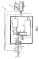
- the figure 1 schematically illustrates a non-destructive control installation of nuclear fuel rods 3 for pressurized water reactor.
- such a rod 3 extends along a longitudinal direction L and comprises a tubular sheath 5 which contains a nuclear fuel, for example in the form of pellets 7 stacked.
- the sheath 5 is closed at its ends by an upper plug 9 and a lower plug 9, which is not visible on the figure 2 but is disposed left on the figure 1 .
- the general structure of the plugs 9 is similar and only that of the upper plug 9 will be described later.
- the upper plug 9 comprises a lower portion 11 which is engaged in the upper end of the sheath 5, substantially without play.
- This lower portion 11 is connected by a shoulder 13 to the running part of the plug 9.
- a circular weld seam 15 extends between this shoulder 13 and the upper edge of the sheath 5.
- This bead 15 ensures the tight attachment of the top plug 9 to the sheath 5.
- the plug 9 further comprises a thinned portion 17 allowing the engagement of gripping jaws.
- the upper plug 9 comprises a channel 19 for filling the sheath 5 with an inert gas under pressure.
- This channel is sometimes referred to as the pressurization channel.
- the channel 19 comprises several successive sections whose diameters are generally decreasing from the portion 11 engaged in the sheath 5 towards the outer end portion 21 of the plug 9.
- the channel 19 comprises a terminal section 23 or exhaust.
- This section 23 opens into the upper end surface of the plug 9 via a circular inlet opening whose center is on the longitudinal axis L.
- the sheath 5 is filled via channel 19 with an inert gas under pressure, such as helium, and then the channel 19 is sealed in its upper section 23.
- an inert gas under pressure such as helium
- this sealing is obtained thanks to a weld point 27 obtained by melting the material of the plug 9 in the vicinity of the upper section 23.
- the source 29, the conversion device 31 and the acquisition device 33 are arranged inside a biological protection chamber 39 which receives the end of the pencil 3 to be examined through an opening 41 capable of be closed, in the absence of pencil 3, by a valve 43. On the figure 1 it is the upper end of the pencil 3 which is introduced into the chamber 39 and which will therefore be controlled.
- the source 29 comprises a tube 45 for creating X-rays and a collimator 47 for orienting the X-rays radially towards the upper plug 9, the tightness of the seals 15 and 27 of which must be checked.
- the source 29 further comprises a shutter 49 which can be controlled, like the tube 45, by the computer system 37.
- the source 29 also includes an image quality indicator (IQI) 51.
- IQI image quality indicator
- Conventionally, such an indicator comprises a plate pierced with two calibrated holes. Comparing the actual dimensions of these holes with those they have on the acquired image makes it possible to ensure the quality of the acquired image.
- the upper plug 9 is engaged in a compensation block 53 which has a substantially parallelepipedal shape and has an inner cavity of a shape substantially complementary to that of the upper end of the rod 3 which it receives.
- This block 53 is made for example of zirconium alloy.
- the X-rays coming from the tube 45 pass through the compensation block 53 and the upper end of the rod 3 radially relative to its longitudinal direction L.
- the X-rays strike the device 31 which is for example a screen comprising an aluminum pellet coated with terbium doped gadolinium oxysulfide.
- the X-rays are then transformed into photons which are returned, via a mirror 55, to the image acquisition device 33.
- This device 33 is for example a CCD camera.
- the camera 33 is connected to the computer system 37 to provide the digital images acquired and be controlled by the latter.
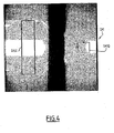
- the acquired image IA1 is represented on the figure 4 .
- the letter A means that it is the image acquired and the number 1, that it is the first shot.
- the dark vertical band in the center corresponds to a lead blanket which has been placed in the compensation block 53 to compensate for the high brightness that the thinned portion 17 of the plug 9 should induce.
- the displacement means 35 include motorized rollers 57 for longitudinally moving the rod 3 and a rotating clamp 59 for rotating it about its axis L, to acquire images from different angles of view.
- the motorized rollers 57 which are controlled by the computer system 37, make it possible to penetrate the end of a pencil 3 to be examined in the enclosure 39, to engage it in the compensation block 53 and to extract it from the enclosure 39 after implementation of the control method described later.
- the displacement means 35 further comprise a sensor 61 for measuring the rotation of the rod 3 connected to the computer system 37.
- This sensor 61 comprises, for example, a wheel resting on the rod 3 to be rotated by the rod 3 when he turns.
- the computer system 37 comprises a computer including itself one or more processors, storage means, input / output means and possibly display means.
- a microcomputer which comprises in particular a screen 63, a central unit 65 and a keyboard 67.
- a program is stored in the computer 37 and allows, in association with an image processing library, the implementation of the non-destructive control method.
- image processing libraries are commonly available commercially.
- the computer 37 will firstly detect and analyze any porosities present in the circular weld bead 15. Such porosities must result in less absorption of the X-rays and therefore of lighter regions.
- a zone IA1C of the acquired image IA1 which corresponds to the region of the pencil 3 containing the weld bead 15 is selected, as illustrated by FIG. figure 4 .
- the letter C means that this zone is relative to the weld bead 15.
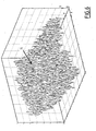
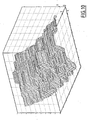
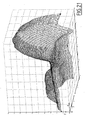
- the figure 5 represents the different gray levels of the IA1C zone. These gray levels were carried along the Oz axis of the Oxyz mark represented in this figure. The Ox and Oy axes have also been materialized on the figure 4 .
- the weld bead 15 has a porosity 71 which is not detectable on the acquired image.
- the figure 6 is an enlarged view of the part of the figure 5 where the porosity 71 is located.
- a reference image IR1C corresponding to a cord 15 which does not contain a defect will be created by digital processing of the area IA1C.
- Convolver g is centered on its central pixel.
- This operation will replace each pixel by the average of the surrounding pixels contained in the convolver centered on the pixel considered. For example with a convolor g of 5 pixels per side, each pixel would be replaced by the average of the pixel and 24 surrounding pixels.
- the IA1C zone resulting from the smoothing step is denoted IL1C.
- the figure 7 is a view similar to the figure 6 at the end of the smoothing step.
- a structuring element h which is a segment, parallel to the axis Ox, and centered on its central pixel.
- This segment has a length of p pixels, p being an integer, preferably between 5 and 21.
- the opening by addition is an erosion by a structuring element followed by an expansion, that is to say a dilation by the same structuring element.
- the opening by adding the structuring element h can therefore be defined by the formula: I ⁇ h ⁇ h
- the erosion corresponds to the first part of this formula and consists in passing the structuring element h on the zone IL1C, as a convolver, and in assigning the minimum value to the central pixel.
- the figure 8 corresponds to the figure 6 after this erosion operation.
- the treated area is then called IE1C.
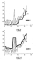
- the figure 9 illustrates schematically and in general the effect of such erosion produced on the variations of the gray levels of an image along the axis Ox.
- Curve 73 corresponds to an image before erosion and curve 75 to an image after erosion.
- Erosion thus keeps the background of the image by eliminating the gray level peaks whose width is smaller than that of the structuring element.
- dilation which is the second part of the opening operation, is to bring back the gray levels of the image where they were before erosion.
- the curve 77 corresponds to an image after dilation.
- the image obtained at the end of this opening operation by addition therefore constitutes a reference image IR1C since the possible defects have been erased.
- the first part of this formula corresponds to a so-called “logarithmic” subtraction.
- the reference image IR1C is not only subtracted from the smoothed image IL1C, but this difference is further divided by one of the terms of the subtraction.
- Such a logarithmic subtraction makes it possible to take into account the absorption of X-rays by the material.
- the multiplier coefficient K is a parameter representative of the camera 33 and can correspond substantially to the dynamic or resolution of the image acquired by the camera 33, that is to say to the maximum value of the light intensity.
- the combination of opening operations by adding the structuring element h and then subtraction can be in fact related to a "top-hat” or “top hat", although in such "top hat” the subtraction not “logarithmic".
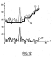
- the curve 78 corresponds to the curve 73 after opening and the curve 79 corresponds to the subtraction of the curve 78 from the original curve 73.
- the figure 13 corresponds to the figure 6 at the end of the treatment of "top-hat” applied by the computer 37.
- the image is then called IS1C.
- the image IS1C will be subjected to an averaging operation, ie to a smoothing, thanks to a convolver j which is also a square, but of larger dimensions than the convolver g.
- this square has for example a square of q pixels, q being an integer, preferably between 5 and 21.
- the image obtained is then called IM1CP.
- the letter P specifies that this image is dedicated to the search for porosities.
- the IM1CP image will then be subjected to a binarization step.
- Such a step consists in displaying the pixels of the image whose gray level is above a determined binarization threshold in white, and displaying in black those whose gray level is below this threshold.
- the binarization threshold which can be modified, corresponds to the desired sensitivity of the analysis.
- the final image at the end of these treatments therefore appears as illustrated by the figure 15 and is designated IF1CP.
- the porosity 71 appears in the form of a white spot or singularity.
- the computer 37 will detect and analyze the defects in the final image IF1 CP.
- the computer 37 uses the singularity search tool or "blobs" of the image processing library which further determines characteristics of the singularities of the IF1CP image, ie porosities thus detected. .
- the computer 37 calculates the position of the porosities and their diameter.
- the computer 37 controls the rotation of the pencil 3 by an angle of 120 °, acquires an image IA2 and then carries out all the operations previously described on its area IA2C, which provides a second IF2CP view of the porosity 71.
- the number 2 means that it is the images relating to the second view.
- the computer 37 again causes a 120 ° rotation of the rod 3 around its longitudinal axis L and acquires an image IA3 in this new position which it treats the IA3C area as previously indicated.
- computer 37 carries out a reconstruction of the detected flaw or faults, in this case porosity 71.
- a porosity detected in the IF1 CP view is selected.
- the computer 37 calculates, from the coordinates of the porosity in the IF1CP view, the coordinates that it could occupy in the IF2CP and IF3CP views. This is the object of step 93.
- step 95 the computer 37 checks whether these computed coordinates correspond to those of a porosity effectively detected in the IF2CP and IF3CP views. If this is not the case, the porosity detected only in the IF1CP view is ignored and the step 91 is performed with another porosity of the IF1 CP view.
- step 95 If the result of the comparison step 95 is positive, the porosity has then been detected in at least two views and the computer 37 can determine in step 97 its exact coordinates and evaluate its actual diameter.
- the actual diameter is calculated from, for example, a formula of the type Am 2 + Bm + c where m is the average of the diameters determined in the two views in which the porosity has been detected.
- the actual diameter is calculated from a formula of the type A 'm + B' where m is the mean diameter of the diameters determined in the three views IF1CP, IF2CP and IF3CP.
- the computer 37 knows the exact positions of the detected porosities and has determined their actual diameters.
- FIG. 17 represents the display on the screen 63 of the weld seam 15 in cross sections and where the only porosity 71 detected is displayed.
- Each of the cross sections corresponds to an angle of view.
- the computer 37 can finally compare the diameters of the detected porosities with a maximum authorized value, as well as comparing the sum of these diameters with a threshold value. If the measured values and the sum are less than the maximum value and the threshold value, the pencil 3 is declared compliant as regards the porosities of the weld bead 15.
- the installation 1 described above then makes it possible to detect and analyze the presence of subpenetration (s) in the weld bead 15.
- the computer 37 processes the images IA1C, IA2C and IA3C.
- the processing operations are the same as those described above with regard to the search for porosities, except that the second step of smoothing or averaging step is performed with a convolver k, which is on the one hand larger dimensions that in the case of the search for porosity and which, on the other hand, is lengthened along the direction Oy, that is to say transversely to the longitudinal axis L.
- This rectangle may for example have r pixels in the Ox direction, r being an integer between 5 and 15, and s side pixels in the direction Oy, where s is an integer, for example between 10 and 20.
- the binarization threshold that is the gray level threshold from which the pixels are displayed in white, is higher than for the porosity search.
- the final images obtained after these treatments are referenced IF1CS, IF2CS, IF3CS.
- the figure 18 illustrates the IF1CS image. This image comes from a succession of images corresponding to each of the processing steps, namely the images IA1C, IL1C, IE1C, ID1C, IS1C, IM1CS and IFCS.
- the letter S indicates that these images are used to search for sub-penetrations.
- the computer 37 can calculate a note relating to the sub-penetrations of the weld bead 15. This note can be the sum of all the surfaces of the subpenetrations 99 detected, possibly weighted.
- the installation 1 then makes it possible to check the seal at the weld point 27 of the filling channel 19 of the sheath 5.
- a zone IA1Q of the acquired image IA1 is selected, as illustrated by FIG. figure 4 .
- the letter Q means that this zone is relative to the verification of the tightness to the right of the 23 exhaust.
- figure 19 illustrates the gray levels in this IA1Q area.
- This image IA1Q is then subjected to a smoothing operation by a convolver 1 which is, for example, a square of t side pixels centered on its central pixel, t being an integer, for example between 3 and 9.
- the size of this convolver is reduced to change the IA1Q image as little as possible.
- the image at the end of this treatment is called IL1Q.
- the image IL1Q is subjected to a projection step along the axis Ox and reconstruction.
- this projection and reconstruction step consists in assigning to the pixel of each column extending along the axis Oy the average value of the gray levels of the pixels of this column.
- IL1Q is therefore to erase any local longitudinal sub-penetrations of the weld point.
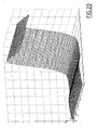
- the image thus obtained is an IR1Q reference image whose gray levels vary only along the direction Ox, as illustrated by the figure 20 .
- the reference image IR1Q is subtracted from the smoothed image IL1Q. This is a simple IL1Q-IR1Q subtraction and not a logarithmic subtraction.
- the figure 21 shows the gray levels after this operation.
- the IS1Q image resulting from the subtraction is binarized in order to obtain a final image IF1Q where all the pixels having a gray level lower than a threshold value are assigned the value zero, and all the others are assigned the value maximum in gray level.
- the figure 22 illustrates the IF1Q image. On the left can be seen the region 101 of the channel 19 under the weld point 27 and on the right the cavity 103 formed above the weld point 27. It will be noted that in the case of TIG welding, the weld point 27 does not form no cavity but has a convex outer surface.
- the computer 37 will detect, by means of the singularity search tool of the image processing library, the zones 101 or 103. If no zone or a single zone traversing horizontally the image IA1Q is detected, the queuing 23 is declared non-welded and the pencil 3 non-compliant. This last case means that the zones 101 or 103 meet. If two zones 101 and 103 are detected, the computer 37 calculates, thanks to the image processing library, the distance between these two zones 101 and 103 which appear in white on the image IF1C. For this purpose, the library, for example, traces the edge 105 of the cavity 103 on the image IF1C and then builds the edge 107 of the zone 101.
- the computer 37 traverses, for each line, the IF1Q image to the right from the left edge of the IF1Q image to find the edge 105.
- the computer 37 travels the line considered in the opposite direction to detect the first white pixel. If it detects such a white pixel, it is the point of the edge 107 of the zone 101 for the line considered. If it does not detect a white pixel, which corresponds in fact to the case where only one zone 103 is present on the right of the image IF1Q, the computer 37 considers that the edge 107 is the left edge of the image IF1Q .
- the computer 37 will determine the coordinates of the points of the edges 105 and 107 of the two light areas 101 and 103.
- the computer 37 will calculate the minimum distance between these edges 105 and 107, which distance corresponds to the axial penetration of the weld point 27 in the channel 19.
- the computer 37 will then proceed thus for the views IA2 and IA3 and provide, from the zones IA2Q and IA3Q, final images IF2Q and IF3Q, and then determine the axial penetrations of the weld point 27 in the channel 19 for each of these views. .
- the computer 37 finally calculates the actual axial penetration of the weld point 27 as being the average of the axial penetrations determined from the three views IF1Q, IF2Q and IF3Q. It finally compares this value with a threshold value, below which it considers that the weld point 27 does not penetrate sufficiently into the channel 19 to seal the rod 3.
- the images IA1Q, IA2Q and IA3Q may be subjected to a treatment for the search for porosities, this treatment being similar to that described previously for the weld bead 15.
- the installation 1 also allows, in the case where the bead 15 and / or the point 17 is / are made by TIG welding to determine the presence of inclusion (s) of tungsten.
- a closing operation is used with a structuring element h. This operation is defined by the formula I ⁇ h ⁇ h
- the structuring element h is then preferably similar to that described above.
- the binarization is reversed compared to that described above.
- it is the subtraction operation that can be inverted, i.e. subtracting the smoothed image from the eroded image, the result being divided by the eroded image and multiplied by the coefficient K.
- the figure 23 thus illustrates the display of the screen 63 for the first viewing angle.
- the upper sequence of images corresponds to the images relating to the search for porosities namely IA1C, IL1C, IE1C, ID1C, IS1C, IM1CP and IF1CP.
- the images IS1C and IM1CP are well present between the images ID1C and IF1CP but are not visible because of their low gray levels.
- the intermediate sequence of images corresponds to an area of the image IA1 in which the orifices of the image quality indicator (IQI) 51 are visible.
- IQI image quality indicator
- the lower succession of lower images corresponds to the sequence of images relating to the weld point 27, namely IA1Q, IL1Q, IR1Q, IS1Q and IF1Q. Note that in the example of the figure 23 , the outlet 23 is not welded.
- the lower part of the screen 63 can provide information relating to the position and diameter of the detected porosities 71, the position and the diameter of the spots 109 detected in the zone corresponding to the indicator of image quality (IQI) 51 as well as information relating to the axial penetration of the weld point 27 for the viewing angle considered.
- IQI indicator of image quality
- the size of the spots detected for the images corresponding to the IQI make it possible to check the reliability of the measurements made.
- the screen 63 may also display in its upper part the succession of images corresponding to the search for sub-penetrations. This is illustrated by the figure 24 .
- the installation 1 made it possible to determine automatically whether the upper plug 9 of the rod 3 had porosities or under-penetrations for the bead 15 or a leakage at the weld point 27, and possibly inclusions of tungsten, justifying the rejection of the pencil 3. Then, one proceeds in a similar manner for the lower plug 9.
- the method described makes it possible to detect and characterize the defects separately and to reconstruct some of them, ie to determine their exact positions and some of their characteristics.
- This reliability and this speed of execution is due to the realization of the reference images, in particular IR1C, IR2C, IR3C, IR1Q, IR2Q and IR3Q from the images acquired IA1C, IA2C, IA3C, IA1Q, IA2Q, and IA3Q.
- a structuring element h in the form of a segment parallel to the axis L is particularly advantageous. Indeed, such a structuring element makes it possible to limit the aberrations introduced into the images because of the presence of the channel 19.
- the structuring element h may not be a segment but may have an elongated shape along the longitudinal axis L. It may thus be a rectangle.
- the above principles namely the creation of a reference image by processing an acquired image of the element to be controlled, can be implemented to control other elements of nuclear reactors than nuclear fuel rods, in particular their welds.
Landscapes
- Physics & Mathematics (AREA)
- Engineering & Computer Science (AREA)
- Health & Medical Sciences (AREA)
- General Physics & Mathematics (AREA)
- General Health & Medical Sciences (AREA)
- Pathology (AREA)
- Life Sciences & Earth Sciences (AREA)
- Chemical & Material Sciences (AREA)
- Analytical Chemistry (AREA)
- Biochemistry (AREA)
- Immunology (AREA)
- Plasma & Fusion (AREA)
- General Engineering & Computer Science (AREA)
- High Energy & Nuclear Physics (AREA)
- Toxicology (AREA)
- Quality & Reliability (AREA)
- Computer Vision & Pattern Recognition (AREA)
- Theoretical Computer Science (AREA)
- Analysing Materials By The Use Of Radiation (AREA)
- Monitoring And Testing Of Nuclear Reactors (AREA)
- Image Processing (AREA)
- Measurement Of Radiation (AREA)
Claims (30)
- Verfahren zur zerstörungsfreien Überwachung eines Elements (3) für einen Kernreaktor, wobei das Verfahren die Schritte umfasst:a) Aufnehmen eines digitalen Röntgenbilds (IA1C, IA2C, IA3C, IA1Q, IA2Q, IA3Q) mindestens einer Zone (15, 27) des Elements (3),b) Herstellen eines Referenzbilds (IR1C, IR2C, IR3C, IR1Q, IR2Q, IR3Q) durch digitale Bearbeitung des aufgenommenen Bilds, undc) Vergleichen des gegebenenfalls bearbeiteten aufgenommenen Bilds (IA1C, IA2C, IA3C, IA1Q, IA2Q, IA3Q) mit dem Referenzbild, um das Vorhandensein eines Fehlers bzw. von Fehlern zu erfassen,wobei das Verfahren dadurch gekennzeichnet ist, dass der Schritt c) einen Teilschritt c1) des Berechnens des Unterschieds zwischen dem gegebenenfalls bearbeiteten aufgenommenen Bild und dem Referenzbild, und des Teilens dieses Unterschieds durch das gegebenenfalls bearbeitete aufgenommene Bild oder das Referenzbild umfasst.
- Verfahren nach Anspruch 1, dadurch gekennzeichnet, dass das Element (3) ein Teil eines Kernbrennstoffsystems ist.
- Verfahren nach Anspruch 2, dadurch gekennzeichnet, dass das Element ein Kernbrennstab (3) ist, der sich entlang einer Längsachse (L) erstreckt, eine durch einen unteren und einen oberen Verschluss (9) verschlossene Hülle (5) umfasst, und einen Kernbrennstoff (7) enthält.
- Verfahren nach Anspruch 3, dadurch gekennzeichnet, dass die Zone eine Schweißnaht (15) zwischen den Verschlüssen (9) und der Hülle (5) umfasst.
- Verfahren nach Anspruch 3, dadurch gekennzeichnet, dass die Zone einen Schweißpunkt umfasst, der einen einen Verschluss (9) durchquerenden Kanal (19) dicht abschließt.
- Verfahren nach einem der vorhergehenden Ansprüche, dadurch gekennzeichnet, dass der Schritt b) einen Teilschritt b1) des Öffnens oder Schließens des Bilds durch Hinzufügen eines strukturierenden Elements (h) umfasst.
- Verfahren nach den zusammengefassten Ansprüchen 3, 4 und 6, dadurch gekennzeichnet, dass das strukturierende Element (h) eine entlang der Längsachse (L) des Stabs (3) ausgedehnte Form hat.
- Verfahren nach Anspruch 7, dadurch gekennzeichnet, dass das strukturierende Element (h) ein Segment aus p Pixeln ist, wobei p eine nicht Null betragende, ganze Zahl ist.
- Verfahren nach Anspruch 7 oder 8, dadurch gekennzeichnet, dass ein zu erfassender Fehler eine Porosität (71) oder eine Schwachstelle (99) der Schweißnaht (15) ist, und dass der Teilschritt b1) ein Teilschritt des Öffnens des Bilds durch Hinzufügen des strukturierenden Elements (h) ist.
- Verfahren nach Anspruch 7 oder 8, dadurch gekennzeichnet, dass ein zu erfassender Fehler ein Wolframeinschluss ist, und dass der Teilschritt b1) ein Teilschritt des Schließens des Bilds durch Hinzufügen des strukturierenden Elements (h) ist.
- Verfahren nach einem der Ansprüche 6 bis 10, dadurch gekennzeichnet, dass der Schritt b) vor dem Teilschritt b1) einen Teilschritt b0) der Glättung des Bilds durch einen Konvolutor (g) umfasst.
- Verfahren nach Anspruch 11, dadurch gekennzeichnet, dass der Konvolutor (g) ein Quadrat mit einer Seitenlänge von n Pixeln ist, wobei n eine nicht Null betragende, ganze Zahl ist.
- Verfahren nach Anspruch 1, dadurch gekennzeichnet, dass es nach dem Teilschritt c1) einen Teilschritt c2) der Multiplikation des Bilds mit einem Faktor umfasst, der im Wesentlichen der maximalen Lichtstärke der Aufnahmevorrichtung (33) entspricht, die zum Aufnehmen des Röntgenbilds verwendet wurde.
- Verfahren nach Anspruch 1 oder 13, dadurch gekennzeichnet, dass es nach dem Teilschritt c1) einen Teilschritt der Glättung des Bilds mittels eines Konvolutors (j, k) umfasst.
- Verfahren nach Anspruch 14, dadurch gekennzeichnet, dass der Konvolutor ein Quadrat mit einer Seitenlänge von q Pixeln ist, wobei q eine ganze Zahl ist.
- Verfahren nach Anspruch 14, dadurch gekennzeichnet, dass der Konvolutor (k) in Bezug auf die Längsachse (L) quer ausgedehnt ist.
- Verfahren nach einem der Ansprüche 1 oder 13 bis 16, dadurch gekennzeichnet, dass es nach dem Teilschritt c1) einen Schritt der Digitalisierung des Bilds umfasst.
- Verfahren nach Anspruch 5, dadurch gekennzeichnet, dass, wenn der zu erfassende Fehler ein Dichtigkeitsfehler an der Stelle des Schweißpunkts (27) ist, der Schritt b) einen Teilschritt b1) der Projizierung des Bilds entlang der Längsachse (L) und der Rekonstruktion des Bilds aus seiner Projektion entlang dieser Achse (L) umfasst.
- Verfahren nach Anspruch 18, dadurch gekennzeichnet, dass der Schritt b) vor dem Teilschritt b1) einen Teilschritt b0) der Glättung des aufgenommenen Bild durch einen Konvolutor (I) umfasst.
- Verfahren nach Anspruch 19, dadurch gekennzeichnet, dass der Konvolutor (I) ein Quadrat mit einer Seitenlänge von t Pixeln ist, wobei t eine ganze Zahl ist.
- Verfahren nach einem der Ansprüche 18 bis 20, dadurch gekennzeichnet, dass es nach dem Teilschritt c1) einen Teilschritt der Digitalisierung des Bilds umfasst.
- Verfahren nach einem der vorhergehenden Ansprüche, dadurch gekennzeichnet, dass das Verfahren einen Schritt d) des automatischen Erfassens und des Bestimmens von Charakteristika eines einem Fehler entsprechenden Bereichs (71; 99) des aus dem Schritt c) hervorgegangenen Bilds umfasst.
- Verfahren nach Anspruch 22, dadurch gekennzeichnet, dass eines der Charakteristika die Position des im Bild erfassten Fehlers ist.
- Verfahren nach Anspruch 22 oder 23, dadurch gekennzeichnet, dass eines der Charakteristika repräsentativ für das Ausmaß des erfassten Fehlers ist.
- Verfahren nach einem der Ansprüche 18 bis 21, dadurch gekennzeichnet, dass es einen Schritt d) der Bestimmung der axialen Mindestdicke des Schweißpunkts (27) umfasst.
- Verfahren nach einem der Ansprüche 22 bis 25, dadurch gekennzeichnet, dass die Schritte a) bis d) für mehrere Blickwinkel durchgeführt werden.
- Verfahren nach den zusammengefassten Ansprüchen 23, 24 und 26, dadurch gekennzeichnet, dass es einen Schritt e) der Rekonstruktion der in den Bildern erfassten Fehler entsprechend verschiedenen Blickwinkeln umfasst.
- Verfahren nach Anspruch 27, dadurch gekennzeichnet, dass der Schritt e) einen Teilschritt e1) der Bestimmung der Positionen, die ein in einem ersten Bild erfasster Fehler entsprechend einem ersten Blickwinkel in einem zweiten Bild entsprechend einem zweiten Blickwinkel einnehmen kann,
einen Teilschritt e2) des Vergleichs der so bestimmten Positionen mit Positionen eines/von tatsächlich im zweiten Bild erfassten Fehlers/Fehlern, um zu bestimmen, ob der Fehler im zweiten Bild erfasst wurde, und, wenn der Fehler im zweiten Bild erfasst wurde,
einen Teilschritt e3) der Berechnung eines Ausmaßes des Fehlers ausgehend von Charakteristika, die repräsentativ für Ausmaße des Fehlers sind, die im ersten und zweiten Bild bestimmt wurden, umfasst. - Verfahren nach den zusammengefassten Ansprüchen 24 und 26, dadurch gekennzeichnet, dass es einen Schritt e) der Summierung der für das Ausmaß repräsentativen Charakteristika, die für mehrere Blickwinkel bestimmt wurden, und des Vergleichs der Summe mit einem Schwellenwert umfasst, um ein Urteil über die Konformität des Elements (3) mit vorbestimmten Herstellungskriterien zu fällen.
- Verfahren nach den zusammengefassten Ansprüchen 25 und 26, dadurch gekennzeichnet, dass es einen Schritt e) der Berechnung eines Mittelwerts der für mehrere Blickwinkel bestimmten Mindestdicken und des Vergleichs mit einem Schwellenwert umfasst, um ein Urteil über die Konformität des Elements (3) mit vorbestimmten Herstellungskriterien zu fällen.
Applications Claiming Priority (2)
| Application Number | Priority Date | Filing Date | Title |
|---|---|---|---|
| FR0313754A FR2862803B1 (fr) | 2003-11-24 | 2003-11-24 | Procede de controle non destructif d'un element pour reacteur nucleaire |
| PCT/FR2004/002895 WO2005062313A2 (fr) | 2003-11-24 | 2004-11-10 | Procede de controle non destructif d'un element pour reacteur nucleaire |
Publications (2)
| Publication Number | Publication Date |
|---|---|
| EP1702340A2 EP1702340A2 (de) | 2006-09-20 |
| EP1702340B1 true EP1702340B1 (de) | 2013-07-24 |
Family
ID=34531227
Family Applications (1)
| Application Number | Title | Priority Date | Filing Date |
|---|---|---|---|
| EP04805436.5A Expired - Lifetime EP1702340B1 (de) | 2003-11-24 | 2004-11-10 | Zerstörungsfreies verfahren zur kontrolle eines kernreaktorelements |
Country Status (6)
| Country | Link |
|---|---|
| US (1) | US7680319B2 (de) |
| EP (1) | EP1702340B1 (de) |
| CN (1) | CN1898698B (de) |
| ES (1) | ES2430369T3 (de) |
| FR (1) | FR2862803B1 (de) |
| WO (1) | WO2005062313A2 (de) |
Families Citing this family (15)
| Publication number | Priority date | Publication date | Assignee | Title |
|---|---|---|---|---|
| DE102009028793B3 (de) * | 2009-07-20 | 2011-01-27 | Areva Np Gmbh | Verfahren und Vorrichtung zum Ermitteln der Verformung eines Brennelementes eines Druckwasserreaktors |
| DE102009047760A1 (de) * | 2009-11-12 | 2011-06-09 | Areva Np Gmbh | Verfahren und Vorrichtung zum Ermitteln der Verformung eines Brennelementes eines Druckwasserreaktors |
| US8693613B2 (en) * | 2010-01-14 | 2014-04-08 | General Electric Company | Nuclear fuel pellet inspection |
| RU2458416C2 (ru) * | 2010-11-15 | 2012-08-10 | Открытое акционерное общество "Машиностроительный завод" | Установка контроля плотности таблеток ядерного топлива |
| FR2979741B1 (fr) * | 2011-09-02 | 2017-03-31 | Areva Np | Dispositif d'examen pour l'examen de composants de reacteur nucleaire |
| US10319484B1 (en) * | 2011-11-17 | 2019-06-11 | Nuscale Power, Llc | Method for imaging a nuclear reactor |
| JP5960502B2 (ja) * | 2012-05-16 | 2016-08-02 | 原子燃料工業株式会社 | X線検査の校正方法、x線検査方法、およびx線検査装置 |
| JP6522299B2 (ja) | 2014-04-01 | 2019-05-29 | ロス アラモス ナショナル セキュリティ,エルエルシー | 原子炉内部の非侵襲的原位置イメージング方法および装置 |
| JP6470506B2 (ja) * | 2014-06-09 | 2019-02-13 | 株式会社キーエンス | 検査装置 |
| DE102015102732A1 (de) * | 2015-02-25 | 2016-08-25 | Areva Gmbh | Vorrichtung und Verfahren zur Prüfung eines Brennstabes eines Brennelements |
| RU2586449C1 (ru) * | 2015-03-27 | 2016-06-10 | федеральное государственное бюджетное образовательное учреждение высшего образования "Ульяновский государственный университет" | Способ контроля сварных соединений мишеней - накопителей и установка для его реализации |
| CN107170499B (zh) * | 2017-05-31 | 2019-08-13 | 岭澳核电有限公司 | 一种核燃料检测装置和方法 |
| CN109521034B (zh) * | 2018-12-29 | 2024-02-09 | 中核北方核燃料元件有限公司 | 一种燃料棒端部焊缝x射线检测补偿块及检测方法 |
| CN110095479B (zh) * | 2019-02-20 | 2022-01-04 | 江苏能建机电实业集团有限公司 | 一种铝型材无损检测设备 |
| CN113178273B (zh) * | 2021-04-30 | 2025-06-10 | 江苏核电有限公司 | 一种核电站焊点打磨模拟装置及其方法 |
Citations (1)
| Publication number | Priority date | Publication date | Assignee | Title |
|---|---|---|---|---|
| US5182775A (en) * | 1990-01-12 | 1993-01-26 | Kawasaki Jukogyo Kabushiki Kaisha | Method of processing radiographic image data for detecting a welding defect |
Family Cites Families (7)
| Publication number | Priority date | Publication date | Assignee | Title |
|---|---|---|---|---|
| DE3809221A1 (de) * | 1988-03-18 | 1989-09-28 | Roth Electric Gmbh | Verfahren zum detektieren von fehlstellen an pressteilen oder anderen werkstuecken und vorrichtung zur durchfuehrung des verfahrens |
| US5309486A (en) * | 1992-11-12 | 1994-05-03 | Westinghouse Electric Corp. | Non-contact flaw detection for cylindrical nuclear fuel pellets |
| WO1997016921A1 (en) * | 1995-10-31 | 1997-05-09 | Sarnoff Corporation | Method and apparatus for generating a reference image from an image sequence |
| US6154561A (en) * | 1997-04-07 | 2000-11-28 | Photon Dynamics, Inc. | Method and apparatus for detecting Mura defects |
| US5999636A (en) * | 1997-10-10 | 1999-12-07 | Printprobe Technology, Llc | Apparatus and process for inspecting print material |
| JP4033369B2 (ja) * | 1999-02-26 | 2008-01-16 | 三菱重工業株式会社 | 原子核燃料棒の検査方法及び検査システム |
| JP3485052B2 (ja) * | 1999-12-16 | 2004-01-13 | 日本電気株式会社 | 参照画像作成方法、パターン検査装置及び参照画像作成プログラムを記録した記録媒体 |
-
2003
- 2003-11-24 FR FR0313754A patent/FR2862803B1/fr not_active Expired - Lifetime
-
2004
- 2004-11-10 WO PCT/FR2004/002895 patent/WO2005062313A2/fr not_active Ceased
- 2004-11-10 EP EP04805436.5A patent/EP1702340B1/de not_active Expired - Lifetime
- 2004-11-10 US US10/580,513 patent/US7680319B2/en active Active
- 2004-11-10 CN CN2004800388596A patent/CN1898698B/zh not_active Expired - Lifetime
- 2004-11-10 ES ES04805436T patent/ES2430369T3/es not_active Expired - Lifetime
Patent Citations (1)
| Publication number | Priority date | Publication date | Assignee | Title |
|---|---|---|---|---|
| US5182775A (en) * | 1990-01-12 | 1993-01-26 | Kawasaki Jukogyo Kabushiki Kaisha | Method of processing radiographic image data for detecting a welding defect |
Non-Patent Citations (4)
| Title |
|---|
| AOKI K. ET AL: "Application of artificial neural network to discrimination of defect type in automatic radiographic testing of welds", ISIJ INTERNATIONAL, vol. 39, no. 10, 1999, JAPAN, pages 1081 - 1087 * |
| FAIVRE M.: "DETECTION ET QUANTIFICATION DE DEFAUTS DANS LES CORDONS DE SOUDURE PAR TRAITEMENT D'IMAGES RADIOSCOPIQUES", REVUE GENERALE DE L'ELECTRICITE, no. 8, 1 September 1988 (1988-09-01), Paris, pages 15 - 18, XP000049972 * |
| KAZANTSEV I.G. ET AL: "Statistical detection of defects in radiographic images in nondestructive testing", SIGNAL PROCESSSING, vol. 82, no. 5, 1 May 2002 (2002-05-01), Amsterdam, pages 791 - 801, XP004354266 * |
| WANG G. ET AL: "Automatic identification of different types of welding defects in radiographic images", NDT&E INTERNATIONAL, vol. 35, no. 8, 1 December 2002 (2002-12-01), pages 519 - 528, XP004395857 * |
Also Published As
| Publication number | Publication date |
|---|---|
| US20070248239A1 (en) | 2007-10-25 |
| CN1898698A (zh) | 2007-01-17 |
| WO2005062313A2 (fr) | 2005-07-07 |
| FR2862803A1 (fr) | 2005-05-27 |
| WO2005062313A3 (fr) | 2005-10-27 |
| CN1898698B (zh) | 2010-05-12 |
| ES2430369T3 (es) | 2013-11-20 |
| FR2862803B1 (fr) | 2007-12-07 |
| EP1702340A2 (de) | 2006-09-20 |
| US7680319B2 (en) | 2010-03-16 |
Similar Documents
| Publication | Publication Date | Title |
|---|---|---|
| EP1702340B1 (de) | Zerstörungsfreies verfahren zur kontrolle eines kernreaktorelements | |
| EP3701222B1 (de) | Verfahren und vorrichtung zur messung von abmessungen durch röntgenstrahlen auf in einer linie verlaufenden leeren glasbehältern | |
| Kim et al. | The influence of X-ray computed tomography acquisition parameters on image quality and probability of detection of additive manufacturing defects | |
| JP2002523740A (ja) | 放射線透過式デジタル型溶接部検査システム | |
| EP0970367A1 (de) | Verfahren zur kontrolle der oberfläcke einer laufenden materialbahn mit bildsegmentierung zur umgrenzung von defektbereichen | |
| FR2730058A1 (fr) | Procede de controle non destructif d'une surface, en particulier en milieu hostile | |
| FR2633793A1 (fr) | Procede de correction de la distorsion d'images radiologiques | |
| EP1264316B1 (de) | Schwei$verfahren zum dichten verschlie$en einer einfüllöffnung eines kernbrennstab-verschlussstücks | |
| WO1998044337A1 (fr) | Procede d'inspection de surface d'une bande en defilement par classification prealable d'irregularite de surface detectee | |
| FR2909207A1 (fr) | Procede de visualisation tridimensionnelle d'images de tomosynthese en mammographie. | |
| EP1214716B1 (de) | Verfahren zur prüfung der schweissverbindung eines kernreaktorbrennstabverschlussstücks | |
| EP2998729A1 (de) | Methode zum korrigieren von artefakten in durch tomographie erhaltenen bildern | |
| EP0542623B1 (de) | Verfahren und Vorrichtung zur Gewinnung und Verarbeitung von Durchleuchtungsbildern | |
| JP2005189175A (ja) | 流動性容器の検査装置および検査方法 | |
| FR3145695A1 (fr) | Procédé d’apprentissage de reconnaissance d’un cordon de soudure conforme | |
| WO2011039427A1 (fr) | Procédé d'examen radio -synthétique de spécimens | |
| FR2707008A1 (en) | Method for inspecting a weld bead, in particular on a motor-vehicle suspension sphere and device for implementing this method | |
| EP0235030A2 (de) | Verfahren zur Feststellung von Fehlern in Metallteilen und Anlage zur Durchführung dieses Verfahrens | |
| CN119595100B (zh) | 大口径纳秒脉冲激光通量的高空间分辨率测量方法及系统 | |
| EP0826960B1 (de) | Verfahren zur automatischen Erfassung von Fehlstellen in mechanischen Werkstücken mit komplizierter Geometrie | |
| EP0216705B1 (de) | Nachprüfungsvorrichtung für durchlaufende zylinderförmige Gegenstände mit Verwendung eindringender Strahlung | |
| Ercelik et al. | Detection of Weld Defects in Power Components Using the Attention-Enhanced YOLOv8 Model | |
| WO2025242758A1 (fr) | Procédé pour améliorer la qualité d'une image bidimensionnelle d'un objet tridimensionnel, et système de traitement de données et dispositif correspondants | |
| BE1027483B1 (fr) | Système et méthode de contrôle qualité de pièces fabriquées | |
| FR3000258A1 (fr) | Procede de localisation et de representation de defaut dans un objet par radiographie, programme d'ordinateur et systeme correspondants |
Legal Events
| Date | Code | Title | Description |
|---|---|---|---|
| PUAI | Public reference made under article 153(3) epc to a published international application that has entered the european phase |
Free format text: ORIGINAL CODE: 0009012 |
|
| 17P | Request for examination filed |
Effective date: 20060522 |
|
| AK | Designated contracting states |
Kind code of ref document: A2 Designated state(s): ES FR GB SE |
|
| 17Q | First examination report despatched |
Effective date: 20061025 |
|
| DAX | Request for extension of the european patent (deleted) | ||
| RBV | Designated contracting states (corrected) |
Designated state(s): ES FR GB SE |
|
| GRAP | Despatch of communication of intention to grant a patent |
Free format text: ORIGINAL CODE: EPIDOSNIGR1 |
|
| INTG | Intention to grant announced |
Effective date: 20130326 |
|
| GRAS | Grant fee paid |
Free format text: ORIGINAL CODE: EPIDOSNIGR3 |
|
| GRAA | (expected) grant |
Free format text: ORIGINAL CODE: 0009210 |
|
| AK | Designated contracting states |
Kind code of ref document: B1 Designated state(s): ES FR GB SE |
|
| REG | Reference to a national code |
Ref country code: GB Ref legal event code: FG4D Free format text: NOT ENGLISH |
|
| RAP2 | Party data changed (patent owner data changed or rights of a patent transferred) |
Owner name: AREVA NP |
|
| REG | Reference to a national code |
Ref country code: SE Ref legal event code: TRGR |
|
| REG | Reference to a national code |
Ref country code: ES Ref legal event code: FG2A Ref document number: 2430369 Country of ref document: ES Kind code of ref document: T3 Effective date: 20131120 |
|
| PLBE | No opposition filed within time limit |
Free format text: ORIGINAL CODE: 0009261 |
|
| STAA | Information on the status of an ep patent application or granted ep patent |
Free format text: STATUS: NO OPPOSITION FILED WITHIN TIME LIMIT |
|
| 26N | No opposition filed |
Effective date: 20140425 |
|
| REG | Reference to a national code |
Ref country code: FR Ref legal event code: ST Effective date: 20140731 |
|
| PG25 | Lapsed in a contracting state [announced via postgrant information from national office to epo] |
Ref country code: FR Free format text: LAPSE BECAUSE OF NON-PAYMENT OF DUE FEES Effective date: 20131202 |
|
| PGFP | Annual fee paid to national office [announced via postgrant information from national office to epo] |
Ref country code: ES Payment date: 20201221 Year of fee payment: 17 Ref country code: SE Payment date: 20201112 Year of fee payment: 17 |
|
| PG25 | Lapsed in a contracting state [announced via postgrant information from national office to epo] |
Ref country code: SE Free format text: LAPSE BECAUSE OF NON-PAYMENT OF DUE FEES Effective date: 20211111 |
|
| REG | Reference to a national code |
Ref country code: ES Ref legal event code: FD2A Effective date: 20230210 |
|
| PG25 | Lapsed in a contracting state [announced via postgrant information from national office to epo] |
Ref country code: ES Free format text: LAPSE BECAUSE OF NON-PAYMENT OF DUE FEES Effective date: 20211111 |
|
| PGFP | Annual fee paid to national office [announced via postgrant information from national office to epo] |
Ref country code: GB Payment date: 20231120 Year of fee payment: 20 |
|
| REG | Reference to a national code |
Ref country code: GB Ref legal event code: PE20 Expiry date: 20241109 |
|
| PG25 | Lapsed in a contracting state [announced via postgrant information from national office to epo] |
Ref country code: GB Free format text: LAPSE BECAUSE OF EXPIRATION OF PROTECTION Effective date: 20241109 |
|
| PG25 | Lapsed in a contracting state [announced via postgrant information from national office to epo] |
Ref country code: GB Free format text: LAPSE BECAUSE OF EXPIRATION OF PROTECTION Effective date: 20241109 |