EP1702174B1 - Vorrichtung zur gezielten, steuerbaren abgabe oder zum ansaugen einer flüssigkeit oder einer viskosen masse - Google Patents
Vorrichtung zur gezielten, steuerbaren abgabe oder zum ansaugen einer flüssigkeit oder einer viskosen masse Download PDFInfo
- Publication number
- EP1702174B1 EP1702174B1 EP04803993A EP04803993A EP1702174B1 EP 1702174 B1 EP1702174 B1 EP 1702174B1 EP 04803993 A EP04803993 A EP 04803993A EP 04803993 A EP04803993 A EP 04803993A EP 1702174 B1 EP1702174 B1 EP 1702174B1
- Authority
- EP
- European Patent Office
- Prior art keywords
- container
- viscous substance
- layers
- wall
- gas
- Prior art date
- Legal status (The legal status is an assumption and is not a legal conclusion. Google has not performed a legal analysis and makes no representation as to the accuracy of the status listed.)
- Expired - Lifetime
Links
- 239000011345 viscous material Substances 0.000 title claims abstract description 10
- 239000007788 liquid Substances 0.000 title claims abstract description 8
- 239000000126 substance Substances 0.000 claims abstract 3
- 230000004888 barrier function Effects 0.000 claims description 8
- 229920003023 plastic Polymers 0.000 claims description 6
- 239000000463 material Substances 0.000 claims description 5
- 238000009792 diffusion process Methods 0.000 claims description 4
- 229920000219 Ethylene vinyl alcohol Polymers 0.000 claims description 3
- UFRKOOWSQGXVKV-UHFFFAOYSA-N ethene;ethenol Chemical compound C=C.OC=C UFRKOOWSQGXVKV-UHFFFAOYSA-N 0.000 claims description 3
- 239000004715 ethylene vinyl alcohol Substances 0.000 claims description 3
- 239000004952 Polyamide Substances 0.000 claims description 2
- 229920002647 polyamide Polymers 0.000 claims description 2
- 230000006698 induction Effects 0.000 claims 1
- 239000007789 gas Substances 0.000 description 17
- 239000000314 lubricant Substances 0.000 description 6
- 239000001257 hydrogen Substances 0.000 description 3
- 229910052739 hydrogen Inorganic materials 0.000 description 3
- UFHFLCQGNIYNRP-UHFFFAOYSA-N Hydrogen Chemical compound [H][H] UFHFLCQGNIYNRP-UHFFFAOYSA-N 0.000 description 2
- 238000010276 construction Methods 0.000 description 2
- 150000002431 hydrogen Chemical class 0.000 description 2
- 239000002184 metal Substances 0.000 description 2
- 239000011248 coating agent Substances 0.000 description 1
- 238000000576 coating method Methods 0.000 description 1
- 230000001419 dependent effect Effects 0.000 description 1
- 238000007599 discharging Methods 0.000 description 1
- 238000001802 infusion Methods 0.000 description 1
- 239000007924 injection Substances 0.000 description 1
- 238000002347 injection Methods 0.000 description 1
- 238000001746 injection moulding Methods 0.000 description 1
- 238000004519 manufacturing process Methods 0.000 description 1
- 238000000465 moulding Methods 0.000 description 1
- 239000003186 pharmaceutical solution Substances 0.000 description 1
- 239000004033 plastic Substances 0.000 description 1
- 238000007789 sealing Methods 0.000 description 1
- 239000007787 solid Substances 0.000 description 1
- 239000011343 solid material Substances 0.000 description 1
Images
Classifications
-
- F—MECHANICAL ENGINEERING; LIGHTING; HEATING; WEAPONS; BLASTING
- F16—ENGINEERING ELEMENTS AND UNITS; GENERAL MEASURES FOR PRODUCING AND MAINTAINING EFFECTIVE FUNCTIONING OF MACHINES OR INSTALLATIONS; THERMAL INSULATION IN GENERAL
- F16N—LUBRICATING
- F16N11/00—Arrangements for supplying grease from a stationary reservoir or the equivalent in or on the machine or member to be lubricated; Grease cups
- F16N11/10—Arrangements for supplying grease from a stationary reservoir or the equivalent in or on the machine or member to be lubricated; Grease cups by pressure of another fluid
Definitions
- the invention relates to a device for targeted, controllable delivery or for sucking a liquid or a viscous mass according to the preamble of claim 1.
- EP 0 598 867 B1 (Wyssmann) known.
- the promotion of small, in particular comparatively valuable liquid or viscous substances according to a predetermined schedule to be followed by means of an autonomous, autonomous control of the program flow - essentially without external intervention - is carried out in particular with devices such as those from the aforementioned generic EP 0 598 867 B1 are known in principle.
- Suitable gas evolution cells for such devices for example, in the DE 35 32 335 A1 (Winsel ) or the EP 0 343 157 B1 (Winsel ).
- a corresponding device for injection or infusion of a pharmaceutical solution can be used, is in the EP 0 278 954 B1 (Winsel) described.
- the invention has the object to remedy this problem.
- the wall of the container is at least partially constructed in three layers. It consists of transparent, translucent layers in such a way that always the filling level remains visible. Unlike a barrier layer made of metal so that the entire cylinder surface can be made translucent.
- the inner and the outer layer of the three-layer structure made of transparent plastic, wherein the middle layer between the two transparent plastic layers of a material, in particular a solid material or a liquid, which is also transparent and has a low diffusion coefficient for that of the gas evolution cell has developed and discharged into the pressure chamber gas.
- the outer and inner layers are made of transparent PET.
- the middle barrier layer further preferably consists in particular of transparent polyamide, which can even be processed as a solid layer and preferably has a thickness of 30-60%, in particular 40-50%, very particularly preferably 45% of the entire wall. This achieves particularly good results and a particularly good compromise between good sealing and stable design is realized.
- EVOH can also be used as a barrier layer.
- Such an arrangement can be manufactured in a modern plastic injection molding process (Coinjection or Multimaterial Molding). For example, it makes sense to use a gas barrier material such as EVOH.
- a particular field of application are lubricators, in which the gas generated by the gas evolution cell and used for propelling the piston is hydrogen.
- the material also lends itself to the realization of corresponding suction devices.
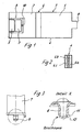
- Figure 1 shows a preferably cylindrical container 7, in which a piston 6 is guided displaceably.
- the piston 6 divides the container 7 in a pressure chamber 2 and a reservoir 1 for viscous mass, in particular lubricants.
- the container 7 has at one of its axial ends - on one side of the piston 6, on which the lubricant 1 is accommodated in the reservoir 1 - an outlet opening 8 and at its opposite axial end, which is directed towards the pressure chamber 2, an insert 9, in which at least one gas evolution cell 3 and an electrical circuit 5 and a device not to be recognized here for runtime control (rotary switch or the like.) Are housed.
- At least one passage opening 10 between the gas evolution cell 3 and the pressure chamber 2 allows the passage of gas, which emits the gas evolution cell 3, in the pressure chamber 2.
- gas especially hydrogen
- the wall 4 of the container 7 in sections, but preferably constructed completely multi-layered. It makes sense to choose a three-layer construction with inner and outer layers 4a, 4c of a transparent plastic to manufacture and between these a barrier layer 4b, in particular from a liquid, a very small diffusion of gas, in particular hydrogen, permitting material train.
- a releasable on a predetermined breaking point 11, in particular break-off closure 12 is formed according to an inventive variant.
- This idea improves the removal of the molded plug on the hopper to the lubricant dispenser.
- the locking pin can be turned off with a standard tool (wrench, pliers), but there are no brews protruding into the pipe cross-section due to the specific shape and the rotational movement.
Landscapes
- Engineering & Computer Science (AREA)
- General Engineering & Computer Science (AREA)
- Mechanical Engineering (AREA)
- Containers And Packaging Bodies Having A Special Means To Remove Contents (AREA)
- Pharmaceuticals Containing Other Organic And Inorganic Compounds (AREA)
- Medicinal Preparation (AREA)
Description
- Die Erfindung betrifft eine Vorrichtung zur gezielten, steuerbaren Abgabe oder zum Ansaugen einer Flüssigkeit oder einer viskosen Masse nach dem Oberbegriff des Anspruches 1.
- Eine derartige Vorrichtung ist aus der
EP 0 598 867 B1 (Wyssmann) bekannt. Die Förderung kleiner, insbesondere vergleichsweise wertvoller flüssiger oder viskoser Substanzen nach einem vorher festgelegten genau einzuhaltenden Zeitplan mittels einer selbsttätigen, autonomen Steuerung des Programmablaufs - im wesentlichen ohne Eingriff von außen - wird insbesondere mit Vorrichtungen durchgeführt, wie sie aus der genannten gattungsgemäßenEP 0 598 867 B1 prinzipiell bekannt sind. - Weiteren Stand der Technik zeigen die
DE 195 22 451 A1 , dieDE 35 32 335 A1 , dieDE 92 02 740 U1 , dieEP 05 98 867 B1 , dieEP 0 362 328 B1 (zweischichtiger Aufbau, transparenter Kunststoff mit gasdichter Metallbeschichtung, die aber nicht durchsichtig ist) und dieEP 0343 157 B1. - Geeignete Gasentwicklungszellen für derartige Vorrichtungen werden beispielsweise in der
DE 35 32 335 A1 (Winsel ) oder derEP 0 343 157 B1 (Winsel ) beschrieben. Eine entsprechende Vorrichtung zur Injektion oder Infusion einer pharmazeutischen Lösung nutzbar ist, ist in derEP 0 278 954 B1 (Winsel) beschrieben. - Die gattungsgemäßen Vorrichtungen haben sich an sich bewährt. Es gibt sie auch als Saugvorrichtungen (Probensammler usw.).
- Zum Stand der Technik wird ferner die
WO 89/08800 A - Problematisch sind aber die insbesondere bei höheren Gegendrücken und/oder Temperaturen und/oder längeren Laufzeiten auftretenden, nicht genau genug kalkulierbaren Verluste aufgrund der Diffusion des von der Gasentwicklungszelle entwickelten Gases zum Antrieb des Kolbens zum Austrag der Flüssigkeit oder der viskosen Masse aus dem Behältnis.
- Die Erfindung hat die Aufgabe, dieses Problem zu beheben.
- Die Erfindung löst diese Aufgabe durch den Gegenstand des Anspruches 1.
- Vorteilhafte Ausgestaltungen sind den Unteransprüchen zu entnehmen.
- Die Wandung des Behältnisses ist zumindest abschnittsweise dreischichtig aufgebaut. Sie besteht aus transparenten, durchscheinenden Schichten derart, dass stets der Füllungsstand sichtbar bleibt. Anders als bei einer Sperrschicht aus Metall kann damit der gesamte Zylindermantel durchscheinend ausgebildet sein.
- Hierbei bestehen die innere und die äußere Schicht des dreischichtigen Aufbaus aus transparentem Kunststoff, wobei die mittlere Schicht zwischen den beiden transparenten Kunststoffschichten aus einem Material, insbesondere einem festen Material oder einer Flüssigkeit besteht, das/die ebenfalls transparent ist und einen geringen Diffusionskoeffizienten für das von der Gasentwicklungszelle entwickelte und in den Druckraum abgegebene Gas aufweist.
- Besonders bevorzugt besteht die äußere und innere Schicht aus transparentem PET. Die mittlere Sperrschicht besteht weiter vorzugsweise aus insbesondere transparentem Polyamid, das sogar als feste Schicht verarbeitet werden kann und hat vorzugsweise eine Dicke von 30 - 60%, insbesondere 40- 50%, ganz besonders bevorzugt 45% der ganzen Wandung. Hiermit werden besonders gute Ergebnisse erzielt und es wird ein besonders guter Kompromiss aus guter Abdichtung und stabiler Auslegung realisiert. Alternativ kann auch EVOH als Sperrschicht verwendet werden.
- Eine derartige Anordnung kann in einem modernen Kunststoffspritzverfahren (Coinjection oder Multimaterial Molding) gefertigt werden. Es bietet sich beispielsweise an, ein Gassperrmaterial wie EVOH zu nutzen.
- Ein besonderes Anwendungsgebiet sind Schmierstoffgeber, bei denen das von der Gasentwicklungszelle erzeugte und zum Vortrieb des Kolbens verwendete Gas Wasserstoff ist. Das Material bietet sich auch zur Realisierung entsprechender Saugvorrichtungen an.
- Nachfolgend wird die Erfindung anhand eines Ausführungsbeispiels unter Bezug auf die Zeichnung näher beschrieben.
- Es zeigt:
- Figur 1
- eine schematische Ansicht einer erfindungsgemäßen Vorrichtung;
- Figur 2
- eine vergrößerte Darstellung der Gehäusewand der Vorrichtung aus Figur 1,
- Figur 3
- ein Detail einer weiteren Vorrichtung.
- Figur 1 zeigt ein vorzugsweise zylindrisches Behältnis 7, in dem ein Kolben 6 verschieblich geführt ist.
- Der Kolben 6 unterteilt das Behältnis 7 in einen Druckraum 2 sowie einen Vorratsraum 1 für viskose Masse, insbesondere Schmierstoffe.
- Das Behältnis 7 weist an einem seiner axialen Enden - auf der einen Seite des Kolbens 6, auf welcher der Schmierstoff 1 im Vorratsraum 1 aufgenommen ist - eine Austrittsöffnung 8 auf und an seinem gegenüberliegenden axialen Ende, welches zum Druckraum 2 hin gerichtet ist, einen Einsatz 9, in dem zumindest eine Gasentwicklungszelle 3 sowie eine elektrische Schaltung 5 und eine hier nicht zu erkennende Einrichtung zur Laufzeitsteuerung (Drehschalter oder dgl.) untergebracht sind.
- Wenigstens eine Durchtrittsöffnung 10 zwischen der Gasentwicklungszelle 3 und dem Druckraum 2 ermöglicht den Durchtritt von Gas, welches die Gasentwicklungszelle 3 abgibt, in den Druckraum 2. Je nach Abhängigkeit der Einstellung der Laufzeitsteuerung - siehe hierzu den genannten Stand der Technik - erfolgt nunmehr die Entwicklung von Gas, insbesondere Wasserstoff, so daß der Kolben 6 von der Gasentwicklungszelle bewegt wird und den Schmierstoff 1 aus der Austrittsöffnung 8 drängt.
- Wie in Figur 2 zu erkennen, ist die Wandung 4 des Behältnisses 7 abschnittsweise, vorzugsweise aber vollständig mehrschichtig aufgebaut. Dabei bietet es sich an, eine dreischichtige Konstruktion zu wählen mit inneren und äußeren Schichten 4a, 4c aus einem transparenten Kunststoff zu fertigen und zwischen diesen eine Sperrschicht 4b, insbesondere aus einem flüssigen, eine nur sehr geringe Diffusion von Gas, insbesondere Wasserstoff, erlaubendem Material auszubilden.
- Auf diese Weise wird nicht nur der Verlust an Gas, insbesondere Wasserstoffgas besonders bei hohem Gegendruck an der Austrittsöffnung deutlich verringert, sondern auch die Genauigkeit der Abgabe der viskosen Masse aus der Vorrichtung, insbesondere bei höheren Drücken oder längeren Abgabezeiten erhöht. So ist es beispielsweise denkbar, mit der erfindungsgemäßen Vorrichtung Schmierstoffe auch über Zeiträume von bis zu einem Jahr oder mehr präzise abzugeben und die Vorrichtung selbst bei Gegendrücken von über 5 bar noch zufriedenstellen zu betreiben. Analoges gilt für erhöhte Temperaturen, die sich auch in einem höheren Druck auswirken können.
- An die Austrittsöffnung 8 wird nach einer erfinderischen Variante ein über eine Sollbruchstelle 11 lösbarer, insbesondere abbrechbarer Verschluß 12 angeformt.
- Diese Idee verbessert das Entfernen des angespritzten Verschlusszapfens am Trichter zu dem Schmierstoffspender.
- Funktion: Der Verschlußzapfen kann mit einem Standardwerkzeug (Schlüssel, Zange) abgedreht werden, dabei entstehen keine, durch die spezifische Formgebung und die Drehbewegung, in den Rohrquerschnitt ragende Brauen.
-
- Schmierstoff
- 1
- Druckraum
- 2
- Gasentwicklungszelle
- 3
- Wandung
- 4
- Elektronikschaltung
- 5
- Kolben
- 6
- Behältnis
- 7
- äußeren Schicht
- 7a, 7c
- Sperrschicht
- 7b
- Austrittsöffnung
- 8
- Einsatz
- 9
- Durchtrittsöffnung
- 10
- Sollbruchstelle
- 11
- Verschluß
- 12
Claims (6)
- Vorrichtung zur gezielten, steuerbaren Abgabe oder zum Ansaugen einer Flüssigkeit oder einer viskosen Masse, mita) einem Behältnis (7), das insbesondere zylindrisch ausgestaltet ist, in dem ein Kolben (6) beweglich, insbesondere verschieblich geführt ist, welcher das Behältnis (7) in einen Vorratsraum (1) für die viskose Masse und einen Druckraum (2) für Gas unterteilt,b) wobei der Vorratsraum (1) für die viskose Masse in einer Austrittsöffnung (8) für die viskose Masse mündet,c) wobei vorzugsweise in das Behältnis (7) im Druckraum (2) ein Einsatz (9) eingesetzt ist, der zumindest eine Gasentwicklungszelle (3) und eine Schaltung zur Laufzeitsteuerung (5) enthält,d) wobei die Wandung des Behältnisses (7) wenigstens zwei Schichten aufweist, die aus verschiedenen chemischen Substanzen bestehen,
dadurch gekennzeichnet, daße) die Wandung des Behältnisses (7) zumindest abschnittsweise dreischichtig, aufgebaut ist, wobei wenigstens zwei der Schichten aus verschiedenen chemischen Substanzen bestehen und wobei die Wandung (4) des Behältnisses (7) aus transparenten, durchscheinenden Schichten besteht,f) die innere und die äußere Schicht (4a, 4c) der dreischichtigen Wandung (7) aus transparentem, durchscheinendem Kunststoff bestehen, wobei die mittlere Schicht (4b) zwischen den beiden transparenten Schichten (4a, 4c) aus einem ebenfalls transparentem Material besteht, das einen geringeren Diffusionskoeffizienten für das von der Gasentwicklungszelle zu entwickelnde Gas aufweist als die innere und die äußere Schicht (4a, 4c). - Vorrichtung nach Anspruch 1, dadurch gekennzeichnet, daß an die Austrittsöffnung (8) ein über Sollbruchstellen (11) wie Kerben lösbarer, insbesondere abbrechbarer Verschluß (11) angeformt ist.
- Vorrichtung nach einem der vorstehenden Ansprüche, dadurch gekennzeichnet, daß die äußere und innere Schicht aus transparentem PET bestehen.
- Vorrichtung nach einem der vorstehenden Ansprüche, dadurch gekennzeichnet, daß die mittlere Sperrschicht aus Polyamid besteht.
- Vorrichtung nach einem der vorstehenden Ansprüche, dadurch gekennzeichnet, daß die mittlere Sperrschicht aus EVOH besteht.
- Vorrichtung nach einem der vorstehenden Ansprüche, dadurch gekennzeichnet, daß die mittlere Sperrschicht eine Dicke von 30 - 60%, vorzugsweise 40- 50%, ganz besonders bevorzugt 45% der ganzen Wandung.
Applications Claiming Priority (2)
| Application Number | Priority Date | Filing Date | Title |
|---|---|---|---|
| DE10360185A DE10360185A1 (de) | 2003-12-20 | 2003-12-20 | Vorrichtung zur gezielten, steuerbaren Abgabe oder zum Ansaugen einer Flüssigkeit oder einer viskosen Masse |
| PCT/EP2004/014384 WO2005061947A1 (de) | 2003-12-20 | 2004-12-17 | Vorrichtung zur gezielten, steuerbaren abgabe oder zum ansaugen einer flüssigkeit oder einer viskosen masse |
Publications (3)
| Publication Number | Publication Date |
|---|---|
| EP1702174A1 EP1702174A1 (de) | 2006-09-20 |
| EP1702174B1 true EP1702174B1 (de) | 2007-11-07 |
| EP1702174B2 EP1702174B2 (de) | 2016-05-18 |
Family
ID=34706377
Family Applications (1)
| Application Number | Title | Priority Date | Filing Date |
|---|---|---|---|
| EP04803993.7A Expired - Lifetime EP1702174B2 (de) | 2003-12-20 | 2004-12-17 | Vorrichtung zur gezielten, steuerbaren abgabe einer flüssigkeit oder einer viskosen masse |
Country Status (5)
| Country | Link |
|---|---|
| US (1) | US20070060865A1 (de) |
| EP (1) | EP1702174B2 (de) |
| AT (1) | ATE377729T1 (de) |
| DE (2) | DE10360185A1 (de) |
| WO (1) | WO2005061947A1 (de) |
Families Citing this family (1)
| Publication number | Priority date | Publication date | Assignee | Title |
|---|---|---|---|---|
| DE102007037422A1 (de) * | 2007-08-08 | 2009-02-19 | Perma-Tec Gmbh & Co. Kg | Schmierstoffspender |
Family Cites Families (20)
| Publication number | Priority date | Publication date | Assignee | Title |
|---|---|---|---|---|
| US3577230A (en) * | 1968-10-18 | 1971-05-04 | Arizona Chem | Process of applying novel algicides |
| JPS6071207A (ja) * | 1983-09-29 | 1985-04-23 | Toyo Seikan Kaisha Ltd | 延伸ブロー成形用多層プリフォームの製造方法 |
| JPS61235126A (ja) * | 1985-04-12 | 1986-10-20 | Nissei Ee S B Kikai Kk | 多層容器の製造方法 |
| DE3532335A1 (de) * | 1985-09-11 | 1987-03-12 | Winsel August | Galvanische zelle zur entwicklung von wasserstoff bzw. sauerstoff |
| DE3621846A1 (de) * | 1986-06-30 | 1988-01-21 | Winsel August | Gasbetriebene dosiervorrichtung |
| DE3643352A1 (de) * | 1986-12-18 | 1988-06-23 | Satzinger Gebhard Gmbh Co | Einrichtung zur elektrochemischen erzeugung von gasen zum transport von fluiden medien |
| ATE126339T1 (de) * | 1988-03-16 | 1995-08-15 | Max Wyssmann | Schmierstoffgeber. |
| DE9202740U1 (de) * | 1992-03-02 | 1992-05-27 | Klöckner Desma GmbH, 47057 Duisburg | Diffusionsfeste Kartusche für plastische Abdichtungsmassen u.dgl. |
| EP0598867B1 (de) * | 1992-06-15 | 1997-03-05 | WYSSMANN, Max | Vorrichtung zur gezielten, steuerbaren abgabe einer flüssigkeit oder einer viskosen masse |
| US5363890A (en) * | 1993-02-05 | 1994-11-15 | Innostar, Inc. | Nonspill bottled water replacement system with disposable seal member |
| US5464106A (en) * | 1994-07-06 | 1995-11-07 | Plastipak Packaging, Inc. | Multi-layer containers |
| US6012551A (en) † | 1995-04-15 | 2000-01-11 | Gerhard Dohring | Apparatus for automatic lubricant delivery |
| DE19522451C2 (de) * | 1995-06-21 | 1997-11-06 | Bernd Hansen | Vorrichtung zur Abgabe eines fließfähigen Stoffes aus einem Behälter |
| DE29602882U1 (de) † | 1996-02-17 | 1996-04-04 | Schieferdecker GmbH & Co KG, 40699 Erkrath | Kartusche |
| US7022112B2 (en) * | 1997-03-21 | 2006-04-04 | Pokorney James L | High pressure syringe |
| US5902598A (en) * | 1997-08-28 | 1999-05-11 | Control Delivery Systems, Inc. | Sustained release drug delivery devices |
| US6312641B1 (en) * | 1997-10-17 | 2001-11-06 | Plastic Fabrication Technologies Llc | Method of making containers and preforms incorporating barrier materials |
| DE29819715U1 (de) † | 1998-11-04 | 1999-01-07 | Kress-Elektrik GmbH & Co Elektromotorenfabrik, 72406 Bisingen | Vorrichtung zum Auspressen und dosierten Abgeben von fließfähigen Massen |
| JP2004532756A (ja) * | 2001-06-18 | 2004-10-28 | ベクトン・ディキンソン・アンド・カンパニー | 多層容器および多層容器の形成方法 |
| DE10247965A1 (de) * | 2002-10-15 | 2004-05-06 | Transcoject Gesellschaft für medizinische Geräte mbH & Co KG | Originalitätsverschluss für eine Spritze |
-
2003
- 2003-12-20 DE DE10360185A patent/DE10360185A1/de not_active Withdrawn
-
2004
- 2004-12-17 AT AT04803993T patent/ATE377729T1/de not_active IP Right Cessation
- 2004-12-17 US US10/596,637 patent/US20070060865A1/en not_active Abandoned
- 2004-12-17 WO PCT/EP2004/014384 patent/WO2005061947A1/de not_active Ceased
- 2004-12-17 DE DE502004005456T patent/DE502004005456D1/de not_active Expired - Lifetime
- 2004-12-17 EP EP04803993.7A patent/EP1702174B2/de not_active Expired - Lifetime
Also Published As
| Publication number | Publication date |
|---|---|
| DE10360185A1 (de) | 2005-08-04 |
| WO2005061947A1 (de) | 2005-07-07 |
| EP1702174B2 (de) | 2016-05-18 |
| DE502004005456D1 (de) | 2007-12-20 |
| ATE377729T1 (de) | 2007-11-15 |
| EP1702174A1 (de) | 2006-09-20 |
| US20070060865A1 (en) | 2007-03-15 |
Similar Documents
| Publication | Publication Date | Title |
|---|---|---|
| DE4102506C2 (de) | Austragvorrichtung für Medien | |
| EP2200752B1 (de) | Dosierungsvorrichtung | |
| EP0753354A2 (de) | Austragvorrichtung für fliessfähige Medien, insbesondere für den Austrag in nur einem Hub | |
| EP2053300B1 (de) | Einleitungsverteiler | |
| EP1383405A1 (de) | Spendervorrichtung für eine cremeförmige oder durch bestreichen einer oberfläche sich abtragenden masse | |
| EP2111120B2 (de) | Vorrichtung zum dosierten zuführen einer fliessfähigen masse | |
| DE202015001781U1 (de) | Zylinder-Kolben-Anordnung für ein Flaschenaufsatzgerät | |
| EP1631767B1 (de) | Verteilerelement für schmieranlagen | |
| WO2016207085A1 (de) | Kabel, verfahren zur herstellung eines kabels und extrusionsanlage | |
| EP3048081A1 (de) | Ventilblockanordnung für ein flaschenaufsatzgerät | |
| EP1752172A1 (de) | Antriebsvorrichtung für eine Infusionspumpe | |
| EP1702174B1 (de) | Vorrichtung zur gezielten, steuerbaren abgabe oder zum ansaugen einer flüssigkeit oder einer viskosen masse | |
| EP2129465B1 (de) | Verfahren und vorrichtung zum dosierten ausbringen eines mediums | |
| EP2158136B1 (de) | Vorrichtung zum austragen einer fliessfähigen substanz | |
| DE3736095C2 (de) | ||
| EP2885088B1 (de) | Austragvorrichtung | |
| DE102013102806A1 (de) | Vorrichtung zur Förderung liquider Medien | |
| DE102014103580B3 (de) | Hydraulischer Dämpfer mit einem Gehäuse, insbesondere für einen Türschließer | |
| EP2488782B1 (de) | Schmierpumpe und schmiermittelversorgungsverfahren | |
| DE102014106458A1 (de) | Verbindungseinrichtung für einen Katheter, insbesondere einen peripheren Venenkatheter (III) | |
| EP2195620A2 (de) | Verfahren und vorrichtung zum dosierten ausbringen eines mediums | |
| DE10121361A1 (de) | Dosiervorrichtung für Schmiermittel | |
| EP4067248A1 (de) | Behältnis mit einem gewinde | |
| DE2738568B2 (de) | Probenahmevorrichtung für Metallschmelzen | |
| EP2199228A1 (de) | Mehrkomponentenkartusche. |
Legal Events
| Date | Code | Title | Description |
|---|---|---|---|
| PUAI | Public reference made under article 153(3) epc to a published international application that has entered the european phase |
Free format text: ORIGINAL CODE: 0009012 |
|
| 17P | Request for examination filed |
Effective date: 20060608 |
|
| AK | Designated contracting states |
Kind code of ref document: A1 Designated state(s): AT BE BG CH CY CZ DE DK EE ES FI FR GB GR HU IE IS IT LI LT LU MC NL PL PT RO SE SI SK TR |
|
| 17Q | First examination report despatched |
Effective date: 20061023 |
|
| DAX | Request for extension of the european patent (deleted) | ||
| GRAP | Despatch of communication of intention to grant a patent |
Free format text: ORIGINAL CODE: EPIDOSNIGR1 |
|
| GRAS | Grant fee paid |
Free format text: ORIGINAL CODE: EPIDOSNIGR3 |
|
| GRAA | (expected) grant |
Free format text: ORIGINAL CODE: 0009210 |
|
| AK | Designated contracting states |
Kind code of ref document: B1 Designated state(s): AT BE BG CH CY CZ DE DK EE ES FI FR GB GR HU IE IS IT LI LT LU MC NL PL PT RO SE SI SK TR |
|
| REG | Reference to a national code |
Ref country code: GB Ref legal event code: FG4D Free format text: NOT ENGLISH |
|
| REG | Reference to a national code |
Ref country code: IE Ref legal event code: FG4D Free format text: LANGUAGE OF EP DOCUMENT: GERMAN |
|
| REG | Reference to a national code |
Ref country code: CH Ref legal event code: EP |
|
| REF | Corresponds to: |
Ref document number: 502004005456 Country of ref document: DE Date of ref document: 20071220 Kind code of ref document: P |
|
| REG | Reference to a national code |
Ref country code: CH Ref legal event code: NV Representative=s name: ISLER & PEDRAZZINI AG |
|
| PG25 | Lapsed in a contracting state [announced via postgrant information from national office to epo] |
Ref country code: SE Free format text: LAPSE BECAUSE OF FAILURE TO SUBMIT A TRANSLATION OF THE DESCRIPTION OR TO PAY THE FEE WITHIN THE PRESCRIBED TIME-LIMIT Effective date: 20080207 Ref country code: ES Free format text: LAPSE BECAUSE OF FAILURE TO SUBMIT A TRANSLATION OF THE DESCRIPTION OR TO PAY THE FEE WITHIN THE PRESCRIBED TIME-LIMIT Effective date: 20080218 Ref country code: NL Free format text: LAPSE BECAUSE OF FAILURE TO SUBMIT A TRANSLATION OF THE DESCRIPTION OR TO PAY THE FEE WITHIN THE PRESCRIBED TIME-LIMIT Effective date: 20071107 |
|
| NLV1 | Nl: lapsed or annulled due to failure to fulfill the requirements of art. 29p and 29m of the patents act | ||
| PG25 | Lapsed in a contracting state [announced via postgrant information from national office to epo] |
Ref country code: PL Free format text: LAPSE BECAUSE OF FAILURE TO SUBMIT A TRANSLATION OF THE DESCRIPTION OR TO PAY THE FEE WITHIN THE PRESCRIBED TIME-LIMIT Effective date: 20071107 Ref country code: IS Free format text: LAPSE BECAUSE OF FAILURE TO SUBMIT A TRANSLATION OF THE DESCRIPTION OR TO PAY THE FEE WITHIN THE PRESCRIBED TIME-LIMIT Effective date: 20080307 Ref country code: SI Free format text: LAPSE BECAUSE OF FAILURE TO SUBMIT A TRANSLATION OF THE DESCRIPTION OR TO PAY THE FEE WITHIN THE PRESCRIBED TIME-LIMIT Effective date: 20071107 Ref country code: BG Free format text: LAPSE BECAUSE OF FAILURE TO SUBMIT A TRANSLATION OF THE DESCRIPTION OR TO PAY THE FEE WITHIN THE PRESCRIBED TIME-LIMIT Effective date: 20080207 Ref country code: LT Free format text: LAPSE BECAUSE OF FAILURE TO SUBMIT A TRANSLATION OF THE DESCRIPTION OR TO PAY THE FEE WITHIN THE PRESCRIBED TIME-LIMIT Effective date: 20071107 |
|
| GBV | Gb: ep patent (uk) treated as always having been void in accordance with gb section 77(7)/1977 [no translation filed] | ||
| BERE | Be: lapsed |
Owner name: WYSSMANN, MAX Effective date: 20071231 |
|
| PG25 | Lapsed in a contracting state [announced via postgrant information from national office to epo] |
Ref country code: CZ Free format text: LAPSE BECAUSE OF FAILURE TO SUBMIT A TRANSLATION OF THE DESCRIPTION OR TO PAY THE FEE WITHIN THE PRESCRIBED TIME-LIMIT Effective date: 20071107 Ref country code: MC Free format text: LAPSE BECAUSE OF NON-PAYMENT OF DUE FEES Effective date: 20071231 Ref country code: DK Free format text: LAPSE BECAUSE OF FAILURE TO SUBMIT A TRANSLATION OF THE DESCRIPTION OR TO PAY THE FEE WITHIN THE PRESCRIBED TIME-LIMIT Effective date: 20071107 |
|
| PLBI | Opposition filed |
Free format text: ORIGINAL CODE: 0009260 |
|
| EN | Fr: translation not filed | ||
| PG25 | Lapsed in a contracting state [announced via postgrant information from national office to epo] |
Ref country code: SK Free format text: LAPSE BECAUSE OF FAILURE TO SUBMIT A TRANSLATION OF THE DESCRIPTION OR TO PAY THE FEE WITHIN THE PRESCRIBED TIME-LIMIT Effective date: 20071107 Ref country code: RO Free format text: LAPSE BECAUSE OF FAILURE TO SUBMIT A TRANSLATION OF THE DESCRIPTION OR TO PAY THE FEE WITHIN THE PRESCRIBED TIME-LIMIT Effective date: 20071107 |
|
| 26 | Opposition filed |
Opponent name: PERMA-TEC GMBH & CO. KG Effective date: 20080807 |
|
| PLAX | Notice of opposition and request to file observation + time limit sent |
Free format text: ORIGINAL CODE: EPIDOSNOBS2 |
|
| PG25 | Lapsed in a contracting state [announced via postgrant information from national office to epo] |
Ref country code: PT Free format text: LAPSE BECAUSE OF FAILURE TO SUBMIT A TRANSLATION OF THE DESCRIPTION OR TO PAY THE FEE WITHIN THE PRESCRIBED TIME-LIMIT Effective date: 20080407 Ref country code: BE Free format text: LAPSE BECAUSE OF NON-PAYMENT OF DUE FEES Effective date: 20071231 |
|
| PG25 | Lapsed in a contracting state [announced via postgrant information from national office to epo] |
Ref country code: IE Free format text: LAPSE BECAUSE OF NON-PAYMENT OF DUE FEES Effective date: 20071217 Ref country code: FR Free format text: LAPSE BECAUSE OF FAILURE TO SUBMIT A TRANSLATION OF THE DESCRIPTION OR TO PAY THE FEE WITHIN THE PRESCRIBED TIME-LIMIT Effective date: 20080822 |
|
| PG25 | Lapsed in a contracting state [announced via postgrant information from national office to epo] |
Ref country code: GB Free format text: LAPSE BECAUSE OF FAILURE TO SUBMIT A TRANSLATION OF THE DESCRIPTION OR TO PAY THE FEE WITHIN THE PRESCRIBED TIME-LIMIT Effective date: 20071107 |
|
| PLAF | Information modified related to communication of a notice of opposition and request to file observations + time limit |
Free format text: ORIGINAL CODE: EPIDOSCOBS2 |
|
| PG25 | Lapsed in a contracting state [announced via postgrant information from national office to epo] |
Ref country code: GR Free format text: LAPSE BECAUSE OF FAILURE TO SUBMIT A TRANSLATION OF THE DESCRIPTION OR TO PAY THE FEE WITHIN THE PRESCRIBED TIME-LIMIT Effective date: 20080208 Ref country code: EE Free format text: LAPSE BECAUSE OF FAILURE TO SUBMIT A TRANSLATION OF THE DESCRIPTION OR TO PAY THE FEE WITHIN THE PRESCRIBED TIME-LIMIT Effective date: 20071107 |
|
| PG25 | Lapsed in a contracting state [announced via postgrant information from national office to epo] |
Ref country code: FI Free format text: LAPSE BECAUSE OF FAILURE TO SUBMIT A TRANSLATION OF THE DESCRIPTION OR TO PAY THE FEE WITHIN THE PRESCRIBED TIME-LIMIT Effective date: 20071107 |
|
| PLBB | Reply of patent proprietor to notice(s) of opposition received |
Free format text: ORIGINAL CODE: EPIDOSNOBS3 |
|
| PG25 | Lapsed in a contracting state [announced via postgrant information from national office to epo] |
Ref country code: AT Free format text: LAPSE BECAUSE OF NON-PAYMENT OF DUE FEES Effective date: 20071217 |
|
| PG25 | Lapsed in a contracting state [announced via postgrant information from national office to epo] |
Ref country code: CY Free format text: LAPSE BECAUSE OF FAILURE TO SUBMIT A TRANSLATION OF THE DESCRIPTION OR TO PAY THE FEE WITHIN THE PRESCRIBED TIME-LIMIT Effective date: 20071107 |
|
| PG25 | Lapsed in a contracting state [announced via postgrant information from national office to epo] |
Ref country code: LU Free format text: LAPSE BECAUSE OF NON-PAYMENT OF DUE FEES Effective date: 20071217 |
|
| PG25 | Lapsed in a contracting state [announced via postgrant information from national office to epo] |
Ref country code: TR Free format text: LAPSE BECAUSE OF FAILURE TO SUBMIT A TRANSLATION OF THE DESCRIPTION OR TO PAY THE FEE WITHIN THE PRESCRIBED TIME-LIMIT Effective date: 20071107 Ref country code: HU Free format text: LAPSE BECAUSE OF FAILURE TO SUBMIT A TRANSLATION OF THE DESCRIPTION OR TO PAY THE FEE WITHIN THE PRESCRIBED TIME-LIMIT Effective date: 20080508 |
|
| APBM | Appeal reference recorded |
Free format text: ORIGINAL CODE: EPIDOSNREFNO |
|
| APBP | Date of receipt of notice of appeal recorded |
Free format text: ORIGINAL CODE: EPIDOSNNOA2O |
|
| APAH | Appeal reference modified |
Free format text: ORIGINAL CODE: EPIDOSCREFNO |
|
| PG25 | Lapsed in a contracting state [announced via postgrant information from national office to epo] |
Ref country code: IT Free format text: LAPSE BECAUSE OF NON-PAYMENT OF DUE FEES Effective date: 20071231 |
|
| APBQ | Date of receipt of statement of grounds of appeal recorded |
Free format text: ORIGINAL CODE: EPIDOSNNOA3O |
|
| PGFP | Annual fee paid to national office [announced via postgrant information from national office to epo] |
Ref country code: CH Payment date: 20121218 Year of fee payment: 9 |
|
| REG | Reference to a national code |
Ref country code: CH Ref legal event code: PL |
|
| PG25 | Lapsed in a contracting state [announced via postgrant information from national office to epo] |
Ref country code: CH Free format text: LAPSE BECAUSE OF NON-PAYMENT OF DUE FEES Effective date: 20131231 Ref country code: LI Free format text: LAPSE BECAUSE OF NON-PAYMENT OF DUE FEES Effective date: 20131231 |
|
| APBU | Appeal procedure closed |
Free format text: ORIGINAL CODE: EPIDOSNNOA9O |
|
| PUAH | Patent maintained in amended form |
Free format text: ORIGINAL CODE: 0009272 |
|
| STAA | Information on the status of an ep patent application or granted ep patent |
Free format text: STATUS: PATENT MAINTAINED AS AMENDED |
|
| 27A | Patent maintained in amended form |
Effective date: 20160518 |
|
| AK | Designated contracting states |
Kind code of ref document: B2 Designated state(s): AT BE BG CH CY CZ DE DK EE ES FI FR GB GR HU IE IS IT LI LT LU MC NL PL PT RO SE SI SK TR |
|
| REG | Reference to a national code |
Ref country code: DE Ref legal event code: R102 Ref document number: 502004005456 Country of ref document: DE |
|
| PGFP | Annual fee paid to national office [announced via postgrant information from national office to epo] |
Ref country code: DE Payment date: 20240122 Year of fee payment: 20 |
|
| REG | Reference to a national code |
Ref country code: DE Ref legal event code: R071 Ref document number: 502004005456 Country of ref document: DE |