EP1702091B1 - Verfahren zur herstellung von nanofasern - Google Patents
Verfahren zur herstellung von nanofasern Download PDFInfo
- Publication number
- EP1702091B1 EP1702091B1 EP03781043A EP03781043A EP1702091B1 EP 1702091 B1 EP1702091 B1 EP 1702091B1 EP 03781043 A EP03781043 A EP 03781043A EP 03781043 A EP03781043 A EP 03781043A EP 1702091 B1 EP1702091 B1 EP 1702091B1
- Authority
- EP
- European Patent Office
- Prior art keywords
- collector
- heater
- heat transfer
- transfer medium
- nanofibers
- Prior art date
- Legal status (The legal status is an assumption and is not a legal conclusion. Google has not performed a legal analysis and makes no representation as to the accuracy of the status listed.)
- Expired - Lifetime
Links
- 239000002121 nanofiber Substances 0.000 title claims abstract description 49
- 238000004519 manufacturing process Methods 0.000 title claims abstract description 17
- 238000009987 spinning Methods 0.000 claims abstract description 19
- 239000007788 liquid Substances 0.000 claims abstract description 14
- 239000000835 fiber Substances 0.000 claims abstract description 12
- 230000015572 biosynthetic process Effects 0.000 claims abstract description 8
- 239000002952 polymeric resin Substances 0.000 claims abstract description 3
- 229920003002 synthetic resin Polymers 0.000 claims abstract description 3
- 238000010041 electrostatic spinning Methods 0.000 claims description 26
- 238000000034 method Methods 0.000 claims description 24
- 239000004033 plastic Substances 0.000 claims description 3
- 229920003023 plastic Polymers 0.000 claims description 3
- XLYOFNOQVPJJNP-UHFFFAOYSA-N water Substances O XLYOFNOQVPJJNP-UHFFFAOYSA-N 0.000 claims description 2
- 239000002904 solvent Substances 0.000 description 31
- 238000010438 heat treatment Methods 0.000 description 24
- 238000009835 boiling Methods 0.000 description 7
- ZMXDDKWLCZADIW-UHFFFAOYSA-N N,N-Dimethylformamide Chemical compound CN(C)C=O ZMXDDKWLCZADIW-UHFFFAOYSA-N 0.000 description 6
- 230000000052 comparative effect Effects 0.000 description 6
- 239000000463 material Substances 0.000 description 5
- XAGFODPZIPBFFR-UHFFFAOYSA-N aluminium Chemical compound [Al] XAGFODPZIPBFFR-UHFFFAOYSA-N 0.000 description 4
- 229910052782 aluminium Inorganic materials 0.000 description 4
- XUIMIQQOPSSXEZ-UHFFFAOYSA-N Silicon Chemical compound [Si] XUIMIQQOPSSXEZ-UHFFFAOYSA-N 0.000 description 3
- 229920000642 polymer Polymers 0.000 description 3
- 229910052710 silicon Inorganic materials 0.000 description 3
- 239000010703 silicon Substances 0.000 description 3
- RYGMFSIKBFXOCR-UHFFFAOYSA-N Copper Chemical compound [Cu] RYGMFSIKBFXOCR-UHFFFAOYSA-N 0.000 description 2
- RYECOJGRJDOGPP-UHFFFAOYSA-N Ethylurea Chemical compound CCNC(N)=O RYECOJGRJDOGPP-UHFFFAOYSA-N 0.000 description 2
- 239000004743 Polypropylene Substances 0.000 description 2
- 230000000903 blocking effect Effects 0.000 description 2
- 229910052802 copper Inorganic materials 0.000 description 2
- 239000010949 copper Substances 0.000 description 2
- 239000003989 dielectric material Substances 0.000 description 2
- 230000000694 effects Effects 0.000 description 2
- -1 polypropylene Polymers 0.000 description 2
- 229920001155 polypropylene Polymers 0.000 description 2
- 229920005749 polyurethane resin Polymers 0.000 description 2
- 229910001220 stainless steel Inorganic materials 0.000 description 2
- 239000010935 stainless steel Substances 0.000 description 2
- 239000000126 substance Substances 0.000 description 2
- 238000009825 accumulation Methods 0.000 description 1
- 238000007599 discharging Methods 0.000 description 1
- 239000012567 medical material Substances 0.000 description 1
- 239000012528 membrane Substances 0.000 description 1
- 239000004745 nonwoven fabric Substances 0.000 description 1
- 239000003921 oil Substances 0.000 description 1
- 239000005022 packaging material Substances 0.000 description 1
- 108090000623 proteins and genes Proteins 0.000 description 1
Images


Classifications
-
- D—TEXTILES; PAPER
- D01—NATURAL OR MAN-MADE THREADS OR FIBRES; SPINNING
- D01D—MECHANICAL METHODS OR APPARATUS IN THE MANUFACTURE OF ARTIFICIAL FILAMENTS, THREADS, FIBRES, BRISTLES OR RIBBONS
- D01D7/00—Collecting the newly-spun products
-
- D—TEXTILES; PAPER
- D01—NATURAL OR MAN-MADE THREADS OR FIBRES; SPINNING
- D01D—MECHANICAL METHODS OR APPARATUS IN THE MANUFACTURE OF ARTIFICIAL FILAMENTS, THREADS, FIBRES, BRISTLES OR RIBBONS
- D01D5/00—Formation of filaments, threads, or the like
- D01D5/0007—Electro-spinning
- D01D5/0061—Electro-spinning characterised by the electro-spinning apparatus
- D01D5/0076—Electro-spinning characterised by the electro-spinning apparatus characterised by the collecting device, e.g. drum, wheel, endless belt, plate or grid
-
- D—TEXTILES; PAPER
- D01—NATURAL OR MAN-MADE THREADS OR FIBRES; SPINNING
- D01F—CHEMICAL FEATURES IN THE MANUFACTURE OF ARTIFICIAL FILAMENTS, THREADS, FIBRES, BRISTLES OR RIBBONS; APPARATUS SPECIALLY ADAPTED FOR THE MANUFACTURE OF CARBON FILAMENTS
- D01F6/00—Monocomponent artificial filaments or the like of synthetic polymers; Manufacture thereof
- D01F6/58—Monocomponent artificial filaments or the like of synthetic polymers; Manufacture thereof from homopolycondensation products
- D01F6/70—Monocomponent artificial filaments or the like of synthetic polymers; Manufacture thereof from homopolycondensation products from polyurethanes
Definitions
- the present invention relates to a method for producing fibers having a thickness of a nano level (hereinafter, 'nanofibers'), and more specifically to a method for producing nanofibers which is capable of effectively preventing nanofibers collected on a collector from being dissolved again by a remaining solvent, especially a solvent with a low volatility (a solvent with a high boiling point) to thus deteriorate fiber formation property by quickly volatilizing the solvent remaining on the collector using the collector with a heater according to claim 1.
- a solvent with a low volatility a solvent with a high boiling point
- the present invention relates to a method capable of mass production of nanofibers at a high efficiency since remaining solvents can be volatilized more efficiently so that nanofibers electrostatically spun and collected on a collector are not dissolved again by the solvents remaining on the collector when nanofibers are produced by using a solvent with a low volatility (a solvent with a high boiling point) or nanofibers are electrostatically spun for a long time by using a solvent with a relatively high volatility (a solvent with a low boiling point) for the purpose of mass production.
- a solvent with a low volatility a solvent with a high boiling point
- nanofibers are electrostatically spun for a long time by using a solvent with a relatively high volatility (a solvent with a low boiling point) for the purpose of mass production.
- Products such as nonwoven fabrics, membranes, braids, etc. composed of nanofibers are widely used for daily necessaries and in agricultural, apparel and industrial applications, etc. Concretely, they are utilized in a wide variety of fields, including artificial leathers, artificial suede, sanitary pads, clothes, diapers, packaging materials, miscellaneous goods materials, a variety of filter materials, medical materials such as gene transfer elements, military materials such as bullet-proof vests, and the like.
- a typical electrostatic spinning apparatus disclosed in U.S Patent No. 4,044,404 comprises a spinning liquid main tank for storing a spinning liquid; a metering pump for constant feeding the spinning liquid; a nozzle block with a plurality of nozzles arranged for discharging the spinning liquid; a collector located on the lower end of the nozzles and for collecting spun fibers; and voltage generators for generating a voltage.
- a spinning liquid in the spinning liquid main tank is continuously constant-fed into the plurality of nozzles with a high voltage through the metering pump.
- the spinning liquid fed into the nozzles is spun on the collector with a high voltage through the nozzles to collect the spun nanofibers on the collector.
- nanofibers are produced by such typical electrostatic spinning method of the prior art, there is a problem that the nanofibers collected on the collector are dissolved by a solvent remaining on the collector to thereby greatly deteriorate the fiber formation ability.
- the above-mentioned problem occurs in a manner that, when nanofibers are electrostatically spun for a long time for the purpose of mass production, the solvent remains on the collector, and accordingly the nanofibers collected on the collector are dissolved.
- the present invention provides a method for producing nanofibers which is capable of effectively preventing nanofibers collected on a collector from being dissolved again by volatilizing the solvent remaining on the collector more quickly during an electrostatic spinning process.
- the present invention provides a method for mass production of nanofibers at higher fiber formation efficiency regardless of a solvent to be used.
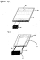
- FIG. 1 is an enlarged schematic view of heater 6 and supporting element 7 sections of direct heating type in a collector.
- Fig. 2 is an enlarged schematic view of heater 6 and supporting element 7 sections of indirect heating type in the collector employed in the present invention.
- a collector 8 with a heater 6 of an indirect heating type as shown in Fig. 2 is employed in order to promote the volatilization of the solvent remaining on the collector when electrostatically spinning nanofibers.
- the collector 8 with the heater 6 of direct heating type can be used a laminate element of a three layer structure which is composed of (i) a supporting element 7 which is a lower end surface, (ii) a conductive plate 5 which is an upper end surface, and (iii) a heater 6 of direct heating type located between the supporting element and the conductive plate.
- the heater 6 of direct heating type can be used a heating plate 6a which has hot wires 6b covered with dielectric polymer arranged at constant intervals and a temperature controller 6c attached thereto.
- the dielectric polymer for covering the hot wires preferably used is silicon having a superior current blocking property.
- Silicon is advantageous in that it is easy to handle with because of a superior flexibility as well as the current flow blocking property.
- the conductive plate 5 to be laminated on the top of the heater 6 is made from a material having a superior conductivity such as aluminum, copper, stainless steel, etc.
- the supporting element 7 located on a lower part of the heater 6 is preferably made from a dielectric material such as plastic or the like in order to minimize heat loss and increase adiabatic effect.
- the surface temperature of the collector 8 can be controlled by the temperature controller 6c connected to the heating plate 6a.
- the collector 8 with the heater 6 of indirect heating type can be used a laminate element of a three layer structure which is composed of (i) a supporting element 7 which is a lower end surface, (ii) a conductive plate 5 which is an upper end surface, and (iii) a heater 6 located between the supporting element and the conductive plate and indirectly heated by heat transfer medium circulation.
- the heater 6 as shown in Fig. 2 , can be used a heater of such a plate type which has a heat transfer medium circulation tube 6e equipped inside and is connected to a circulation type heat reservoir 6d through a heat transfer medium feed section 6f and a heat transfer medium discharge section 6g.
- heat transfer medium can be used water, steam or oil.
- the present invention does not specifically limit the type of the heat transfer medium.
- the conductive plate 5 laminated on the top of the heater 6 is made from a material having a superior conductivity such as aluminum, copper, stainless steel, etc.
- the supporting element 7 located on a lower part of the heater 6 is preferably made from a dielectric material such as plastic or the like in order to minimize heat loss and increase adiabatic effect.
- the heater 6 is heated by circulating the heat transfer medium heated in the circulation type heat reservoir 6d into the heat transfer medium circulation tube 6e in the heater 6 during electrostatic spinning, and the heat generated from the heater 6 is conducted to the conductive plate 5 forming the surface of the collector 8, to thereby quickly volatilize the solvent remaining on the collector 8.
- the heat transfer medium is heated at a desired temperature in the circulation type heat reservoir 6d.
- the heated heat transfer medium is introduced into the heat transfer medium circulation tube 6e equipped in the heater 6 through the heat transfer medium feed section 6f, and then indirectly heats the heater 6 while flowing along the heat transfer medium circulation tube 6e.
- the heat transfer medium whose temperature is lowered is circulated into the circulation type heat reservoir 6d through the heat transfer medium discharge section 6g and is heated again at a desired temperature. This circulation procedure is repeated.
- the surface temperature of the collector 8 is properly controlled as needed.
- the temperature preferably ranges from a room temperature to 300°C, and more preferably from a room temperature to 200°C.
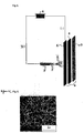
- Fig. 3 is a process schematic view of the production of nanofibers in a top-down electrostatic spinning type by utilizing the collector 8 with the heater 6 according to the present invention.
- Fig. 4 is a process schematic view of the production of nanofibers in a down-top electrostatic spinning type by utilizing the collector 8 with the heater 6 according to the present invention.
- Fig. 5 is a process schematic view of the production of nanofibers in a horizontal electrostatic spinning type by utilizing the collector 8 with the heater 6 according to the present invention.
- the collector 8 with the heater 6 of this invention is applicable regardless of angles of the nozzle and collector.
- the present invention is applicable to all of the top-down electrostatic spinning, down-top electrostatic spinning and horizontal electrostatic spinning as shown in Figs. 3 to 5 .
- the present invention employs the collector 8 with the heater 6 of indirect heating type, thus it can volatilize the solvent remaining on the collector 8 within a short time. Subsequently, it is possible to prevent the phenomenon that the nanofibers collected on the collector 8 are dissolved again by the remaining solvent, thereby improving fiber formation efficiency even in the case that a solvent with a low volatility (a solvent with a high boiling point) is used.
- the present invention is capable of mass production of nanofibers for a long time by using a solvent with a high volatility (a solvent with a low boiling point).
- the voltage was 30kV and the spinning distance was 20cm.
- a voltage generator Model CH 50 of Simco Company was used.
- a nozzle plate a nozzle plate with 2,000 holes (nozzles) having a 0.8 diameter uniformly arranged was used.
- a collector 8 a laminate element of a three layer structure which is composed of (i) a supporting element 7 of a polypropylene plate, (ii) a heater 6 of direct heating type located on the supporting element and composed of a heating plate 6a which has hot wires 6b covered with silicon arranged at constant intervals and a temperature controller 6c attached thereto, and (iii) a conductive plate 5 made from an aluminum film and located on top of the heater.
- the surface temperature of the collector was 95°C.
- the voltage was 30kV and the spinning distance was 20cm.
- a voltage generator Model CH 50 of Simco Company is used.
- a nozzle plate a nozzle plate with 2,000 holes (nozzles) having a 0.8 diameter uniformly arranged was used.
- a collector 8 a laminate element of a three layer structure which is composed of (i) a supporting element 7 of a polypropylene plate, (ii) a heater 6 of such a plate type that has a heat transfer medium circulation tube 6e equipped inside and is connected to a circulation type heat reservoir 6d by a heat transfer medium feed section 6f and a heat transfer medium discharge section 6g, and (iii) a conductive plate 5 made from an aluminum film and located on top of the heater.
- the surface temperature of the collector was 85°C.
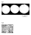
- FIG. 7 An enlarged photograph of the portion of a produced nanofiber web spun into three holes is as shown in Fig. 7 .
- Nanofibers were produced in the same process and method as in Reference Example 1 except that a typical collector with no heater 6 attached thereto was used in place of the collector 8 with a heater 6 of direct or indirect heating type of Reference Example 1 or Example 2.
- FIG. 8 An enlarged photograph of a produced nanofiber web is as shown in Fig. 8 , and an enlarged photograph of the portion of a produced nanofiber web spun into three holes is as shown in Fig. 9 .
- the present invention can quickly volatilize the solvent remaining on the collector during an electrostatic spinning process and thus effectively prevent the nanofibers collected on the collector from being dissolved.
- the present invention is capable of mass production of nanofibers regardless of the type of a solvent to be used and capable of greatly improving fiber formation efficiency.
Landscapes
- Engineering & Computer Science (AREA)
- Textile Engineering (AREA)
- Mechanical Engineering (AREA)
- Chemical & Material Sciences (AREA)
- Chemical Kinetics & Catalysis (AREA)
- General Chemical & Material Sciences (AREA)
- Spinning Methods And Devices For Manufacturing Artificial Fibers (AREA)
- Chemical Treatment Of Fibers During Manufacturing Processes (AREA)
- Nonwoven Fabrics (AREA)
Claims (6)
- Verfahren zur Herstellung von Nanofasern mit einer exzellenten Faserbildungseigenschaft, dadurch gekennzeichnet, dass: wenn Nanofasern (3) mit einer Dicke auf einem Nanolevel durch elektrostatisches Spinnen einer Spinnflüssigkeit (1) aus einer Polymerharzlösung auf einem Kollektor (8) durch eine Düse (2) unter Hochspannung hergestellt werden, ein Kollektor (8) mit einem Heizgerät (6) als Kollektor (8) verwendet wird, wobei das Heizgerät (6) ein Heizgerät ist, das indirekt durch Zirkulation eines Hitzetransfermediums beheizt wird.
- Verfahren nach Anspruch 1, wobei der Kollektor (8) mit dem Heizgerät (6) ein Laminatelement mit einer Dreischichtstruktur darstellt, die aus (i) einem Trägerelement (7), das eine untere Stirnfläche darstellt, (ii) einer leitenden Platte (5), die eine obere Stirnfläche darstellt und (iii) einem Heizgerät (6), das sich zwischen dem Trägerelement und der leitenden Platte befindet und indirekt durch Zirkulation eines Hitzetransfermediums beheizt wird, aufgebaut ist.
- Verfahren nach Anspruch 1 oder 2, wobei das Hitzetransfermedium Wasser, Dampf oder Öl ist.
- Verfahren nach Anspruch 1 oder 2, wobei das Heizgerät (6) von einer solchen Plattenart ist, die innen mit einem Hitzetransfermediumzirkulationsrohr (6e) ausgestattet ist und die mit einem Hitzereservoir (6d) der Zirkulationsart durch einen Zuführbereich (6f) des Hitzetransfermediums und einem Austrittsbereich (6g) des Hitzetransfermediums verbunden ist.
- Verfahren nach Anspruch 2, wobei das Trägerelement (7) aus Plastik hergestellt ist, das dielektrisch ist.
- Verfahren nach Anspruch 1, wobei das elektrostatische Spinnverfahren eine top-down elektrostatische Spinnart, eine down-top elektrostatische Spinnart oder eine horizontale elektrostatische Spinnart ist.
Applications Claiming Priority (1)
| Application Number | Priority Date | Filing Date | Title |
|---|---|---|---|
| PCT/KR2003/002883 WO2005064048A1 (en) | 2003-12-30 | 2003-12-30 | A method manufacturing nano-fibers with excellent fiber formation |
Publications (3)
| Publication Number | Publication Date |
|---|---|
| EP1702091A1 EP1702091A1 (de) | 2006-09-20 |
| EP1702091A4 EP1702091A4 (de) | 2008-05-21 |
| EP1702091B1 true EP1702091B1 (de) | 2010-02-10 |
Family
ID=34737815
Family Applications (1)
| Application Number | Title | Priority Date | Filing Date |
|---|---|---|---|
| EP03781043A Expired - Lifetime EP1702091B1 (de) | 2003-12-30 | 2003-12-30 | Verfahren zur herstellung von nanofasern |
Country Status (6)
| Country | Link |
|---|---|
| US (1) | US20070152378A1 (de) |
| EP (1) | EP1702091B1 (de) |
| JP (1) | JP4509937B2 (de) |
| AT (1) | ATE457374T1 (de) |
| DE (1) | DE60331264D1 (de) |
| WO (1) | WO2005064048A1 (de) |
Cited By (1)
| Publication number | Priority date | Publication date | Assignee | Title |
|---|---|---|---|---|
| CZ304660B6 (cs) * | 2013-05-22 | 2014-08-20 | Malm S.R.O. | Způsob a zařízení pro výrobu vrstvy vláken, zejména nanovláken, mikrovláken nebo jejich směsí, s vlákny orientovanými v jednom směru, a kolektor tohoto zařízení pro ukládání vláken |
Families Citing this family (24)
| Publication number | Priority date | Publication date | Assignee | Title |
|---|---|---|---|---|
| WO2007095363A2 (en) | 2006-02-13 | 2007-08-23 | Donaldson Company, Inc. | Filter web comprising fine fiber and reactive, adsorptive or absorptive particulate |
| US7981509B2 (en) | 2006-02-13 | 2011-07-19 | Donaldson Company, Inc. | Polymer blend, polymer solution composition and fibers spun from the polymer blend and filtration applications thereof |
| KR20090108024A (ko) * | 2007-01-12 | 2009-10-14 | 다우 코닝 코포레이션 | 실리콘 함유 조성물 |
| JP4831350B2 (ja) * | 2007-01-25 | 2011-12-07 | トヨタ紡織株式会社 | 電界紡糸方法 |
| WO2008101051A2 (en) * | 2007-02-14 | 2008-08-21 | Dow Global Technologies Inc. | Polymer or oligomer fibers by solvent-free electrospinning |
| JP5150140B2 (ja) * | 2007-06-08 | 2013-02-20 | 日本バイリーン株式会社 | 極細繊維不織布及びその製造方法 |
| JP4886610B2 (ja) * | 2007-06-11 | 2012-02-29 | 日本バイリーン株式会社 | 静電紡糸不織布の製造方法 |
| JP5284617B2 (ja) * | 2007-10-18 | 2013-09-11 | 株式会社カネカ | 高分子繊維及びその製造方法、製造装置 |
| CN101977524A (zh) * | 2008-01-18 | 2011-02-16 | Mmi-Ipco有限责任公司 | 复合织物 |
| JP5380012B2 (ja) * | 2008-07-30 | 2014-01-08 | 国立大学法人信州大学 | 電界紡糸装置 |
| CZ201093A3 (cs) * | 2010-02-05 | 2011-08-17 | Cpn S.R.O. | Zarízení pro výrobu dvojrozmerných nebo trojrozmerných vlákenných materiálu z mikrovláken nebo nanovláken |
| US10149749B2 (en) | 2010-06-17 | 2018-12-11 | Washington University | Biomedical patches with aligned fibers |
| US8835141B2 (en) | 2011-06-09 | 2014-09-16 | The United States Of America As Represented By The Secretary Of Agriculture | Methods for integrated conversion of lignocellulosic material to sugars or biofuels and nano-cellulose |
| GB201113060D0 (en) * | 2011-07-29 | 2011-09-14 | Univ Ulster | Tissue scaffold |
| US20150230918A1 (en) * | 2011-08-16 | 2015-08-20 | The University Of Kansas | Biomaterial based on aligned fibers, arranged in a gradient interface, with mechanical reinforcement for tracheal regeneration and repair |
| JP6295258B2 (ja) | 2012-09-21 | 2018-03-14 | ワシントン・ユニバーシティWashington University | 空間的に配置された繊維を有する医用パッチ |
| GB201409047D0 (en) * | 2014-05-21 | 2014-07-02 | Cellucomp Ltd | Cellulose microfibrils |
| CN104313799B (zh) * | 2014-09-29 | 2017-05-24 | 中鸿纳米纤维技术丹阳有限公司 | 一种纳米纤维成网装置 |
| CN106222762A (zh) * | 2016-04-14 | 2016-12-14 | 浙江海洋学院 | 纳米纤维静电纺丝设备及其使用方法 |
| US10632228B2 (en) | 2016-05-12 | 2020-04-28 | Acera Surgical, Inc. | Tissue substitute materials and methods for tissue repair |
| GB2553316B (en) * | 2016-09-01 | 2020-05-13 | Univ Nottingham Trent | Method and apparatus for fabricating a fibre array and structure incorporating a fibre array |
| JP2024536674A (ja) | 2021-07-29 | 2024-10-08 | アセラ サージカル インコーポレイテッド | 粒子状ハイブリッドスケール繊維マトリックス |
| WO2023007444A1 (en) | 2021-07-29 | 2023-02-02 | Acera Surgical, Inc. | Combined macro and micro-porous hybrid-scale fiber matrix |
| WO2023039381A1 (en) | 2021-09-07 | 2023-03-16 | Acera Surgical, Inc. | Materials and methods for nerve repair and regeneration |
Family Cites Families (9)
| Publication number | Priority date | Publication date | Assignee | Title |
|---|---|---|---|---|
| CA2070589C (en) * | 1991-12-19 | 2000-11-28 | Kimberly-Clark Corporation | Method of preparing a nonwoven web of poly (vinyl alcohol) fibers |
| JP4114232B2 (ja) * | 1998-05-14 | 2008-07-09 | コニカミノルタホールディングス株式会社 | セルローストリアセテート溶液の調製方法、セルローストリアセテートフィルムの製造方法及びセルローストリアセテートフィルム |
| US6743273B2 (en) * | 2000-09-05 | 2004-06-01 | Donaldson Company, Inc. | Polymer, polymer microfiber, polymer nanofiber and applications including filter structures |
| US20020084178A1 (en) * | 2000-12-19 | 2002-07-04 | Nicast Corporation Ltd. | Method and apparatus for manufacturing polymer fiber shells via electrospinning |
| KR100406981B1 (ko) * | 2000-12-22 | 2003-11-28 | 한국과학기술연구원 | 전하 유도 방사에 의한 고분자웹 제조 장치 및 그 방법 |
| KR20020063020A (ko) * | 2001-01-26 | 2002-08-01 | 한국과학기술연구원 | 미세 섬유상 고분자웹의 제조 방법 |
| US6713011B2 (en) * | 2001-05-16 | 2004-03-30 | The Research Foundation At State University Of New York | Apparatus and methods for electrospinning polymeric fibers and membranes |
| KR100395696B1 (ko) * | 2001-06-07 | 2003-08-25 | 주식회사 나노테크닉스 | 탄화규소 단섬유의 제조방법 |
| WO2003087443A1 (en) * | 2002-04-11 | 2003-10-23 | Secant Medical, Inc. | Covering process using electrospinning of very small fibers |
-
2003
- 2003-12-30 DE DE60331264T patent/DE60331264D1/de not_active Expired - Lifetime
- 2003-12-30 EP EP03781043A patent/EP1702091B1/de not_active Expired - Lifetime
- 2003-12-30 WO PCT/KR2003/002883 patent/WO2005064048A1/en not_active Ceased
- 2003-12-30 JP JP2005512810A patent/JP4509937B2/ja not_active Expired - Fee Related
- 2003-12-30 US US10/584,411 patent/US20070152378A1/en not_active Abandoned
- 2003-12-30 AT AT03781043T patent/ATE457374T1/de not_active IP Right Cessation
Cited By (1)
| Publication number | Priority date | Publication date | Assignee | Title |
|---|---|---|---|---|
| CZ304660B6 (cs) * | 2013-05-22 | 2014-08-20 | Malm S.R.O. | Způsob a zařízení pro výrobu vrstvy vláken, zejména nanovláken, mikrovláken nebo jejich směsí, s vlákny orientovanými v jednom směru, a kolektor tohoto zařízení pro ukládání vláken |
Also Published As
| Publication number | Publication date |
|---|---|
| DE60331264D1 (de) | 2010-03-25 |
| JP4509937B2 (ja) | 2010-07-21 |
| ATE457374T1 (de) | 2010-02-15 |
| EP1702091A1 (de) | 2006-09-20 |
| EP1702091A4 (de) | 2008-05-21 |
| WO2005064048A1 (en) | 2005-07-14 |
| US20070152378A1 (en) | 2007-07-05 |
| JP2007528449A (ja) | 2007-10-11 |
Similar Documents
| Publication | Publication Date | Title |
|---|---|---|
| EP1702091B1 (de) | Verfahren zur herstellung von nanofasern | |
| JP4402695B2 (ja) | 上向式エレクトロスピニング装置及びこれを用いて製造されたナノ繊維 | |
| KR101060866B1 (ko) | 전기방사용 방사 팩 및 이를 이용하는 전기방사장치 | |
| JP4414458B2 (ja) | 上向式エレクトロスピニング装置及びこれを用いて製造されたナノ繊維 | |
| US20140179889A1 (en) | Apparatus and Method for Elevated Temperature Electrospinning | |
| KR101060918B1 (ko) | 전기방사용 다중 노즐 방사 팩 및 이를 포함하는 전기방사장치 | |
| KR101354509B1 (ko) | 나노섬유 필라멘트의 제조방법 | |
| CN101586288A (zh) | 阵列多喷头静电纺丝设备 | |
| CN109208090B (zh) | 一种新型无针静电纺丝装置及其纺丝方法 | |
| CN103060932A (zh) | 一种转鼓式静电纺丝装置 | |
| CN106906635A (zh) | 一种医疗用高吸收率亲水性无纺布的整理方法 | |
| Ramakrishnan et al. | Needleless electrospinning technology–an entrepreneurial perspective | |
| Kouhi et al. | Needleless electrospinning | |
| KR20110074085A (ko) | 고온 전기방사장치 | |
| KR100562006B1 (ko) | 상향식 전기방사장치 및 이를 이용하여 제조된 나노섬유 | |
| KR101617848B1 (ko) | 온도조절 장치를 포함하는 나노섬유 제조용 전기방사 장치 | |
| KR100562018B1 (ko) | 섬유형성능이 우수한 나노섬유의 제조방법 | |
| KR101118079B1 (ko) | 나노섬유 웹의 제조방법 | |
| KR100595484B1 (ko) | 섬유형성능이 우수한 나노섬유의 제조방법 | |
| KR100696319B1 (ko) | 다공성 나노섬유 및 그의 제조방법 | |
| KR20100070203A (ko) | 수직 기류 및 원심력을 이용한 나노섬유로 구성된 섬유집합체의 제조장치 및 제조방법 | |
| KR101635024B1 (ko) | 용매 잔존량이 낮은 나노섬유 및 이의 제조방법 | |
| KR101753052B1 (ko) | 온도조절 장치를 포함하는 나노 멤브레인 전기방사 장치 | |
| KR100712592B1 (ko) | 용융 전기 방사 장치 | |
| Manea et al. | Melt Electrospinning–Characteristics, Application Areas and Perspectives |
Legal Events
| Date | Code | Title | Description |
|---|---|---|---|
| PUAI | Public reference made under article 153(3) epc to a published international application that has entered the european phase |
Free format text: ORIGINAL CODE: 0009012 |
|
| 17P | Request for examination filed |
Effective date: 20060627 |
|
| AK | Designated contracting states |
Kind code of ref document: A1 Designated state(s): AT BE BG CH CY CZ DE DK EE ES FI FR GB GR HU IE IT LI LU MC NL PT RO SE SI SK TR |
|
| DAX | Request for extension of the european patent (deleted) | ||
| A4 | Supplementary search report drawn up and despatched |
Effective date: 20080418 |
|
| RIC1 | Information provided on ipc code assigned before grant |
Ipc: D01D 5/00 20060101AFI20080414BHEP |
|
| 17Q | First examination report despatched |
Effective date: 20081118 |
|
| GRAP | Despatch of communication of intention to grant a patent |
Free format text: ORIGINAL CODE: EPIDOSNIGR1 |
|
| RTI1 | Title (correction) |
Free format text: A METHOD OF MANUFACTURING NANO-FIBERS |
|
| GRAS | Grant fee paid |
Free format text: ORIGINAL CODE: EPIDOSNIGR3 |
|
| GRAA | (expected) grant |
Free format text: ORIGINAL CODE: 0009210 |
|
| AK | Designated contracting states |
Kind code of ref document: B1 Designated state(s): AT BE BG CH CY CZ DE DK EE ES FI FR GB GR HU IE IT LI LU MC NL PT RO SE SI SK TR |
|
| REG | Reference to a national code |
Ref country code: GB Ref legal event code: FG4D |
|
| REG | Reference to a national code |
Ref country code: CH Ref legal event code: EP Ref country code: CH Ref legal event code: NV Representative=s name: BOHEST AG |
|
| REG | Reference to a national code |
Ref country code: IE Ref legal event code: FG4D |
|
| REF | Corresponds to: |
Ref document number: 60331264 Country of ref document: DE Date of ref document: 20100325 Kind code of ref document: P |
|
| REG | Reference to a national code |
Ref country code: NL Ref legal event code: VDEP Effective date: 20100210 |
|
| PG25 | Lapsed in a contracting state [announced via postgrant information from national office to epo] |
Ref country code: PT Free format text: LAPSE BECAUSE OF FAILURE TO SUBMIT A TRANSLATION OF THE DESCRIPTION OR TO PAY THE FEE WITHIN THE PRESCRIBED TIME-LIMIT Effective date: 20100611 Ref country code: ES Free format text: LAPSE BECAUSE OF FAILURE TO SUBMIT A TRANSLATION OF THE DESCRIPTION OR TO PAY THE FEE WITHIN THE PRESCRIBED TIME-LIMIT Effective date: 20100521 |
|
| PG25 | Lapsed in a contracting state [announced via postgrant information from national office to epo] |
Ref country code: SI Free format text: LAPSE BECAUSE OF FAILURE TO SUBMIT A TRANSLATION OF THE DESCRIPTION OR TO PAY THE FEE WITHIN THE PRESCRIBED TIME-LIMIT Effective date: 20100210 Ref country code: FI Free format text: LAPSE BECAUSE OF FAILURE TO SUBMIT A TRANSLATION OF THE DESCRIPTION OR TO PAY THE FEE WITHIN THE PRESCRIBED TIME-LIMIT Effective date: 20100210 Ref country code: AT Free format text: LAPSE BECAUSE OF FAILURE TO SUBMIT A TRANSLATION OF THE DESCRIPTION OR TO PAY THE FEE WITHIN THE PRESCRIBED TIME-LIMIT Effective date: 20100210 |
|
| PG25 | Lapsed in a contracting state [announced via postgrant information from national office to epo] |
Ref country code: NL Free format text: LAPSE BECAUSE OF FAILURE TO SUBMIT A TRANSLATION OF THE DESCRIPTION OR TO PAY THE FEE WITHIN THE PRESCRIBED TIME-LIMIT Effective date: 20100210 Ref country code: GR Free format text: LAPSE BECAUSE OF FAILURE TO SUBMIT A TRANSLATION OF THE DESCRIPTION OR TO PAY THE FEE WITHIN THE PRESCRIBED TIME-LIMIT Effective date: 20100511 Ref country code: BE Free format text: LAPSE BECAUSE OF FAILURE TO SUBMIT A TRANSLATION OF THE DESCRIPTION OR TO PAY THE FEE WITHIN THE PRESCRIBED TIME-LIMIT Effective date: 20100210 Ref country code: CY Free format text: LAPSE BECAUSE OF FAILURE TO SUBMIT A TRANSLATION OF THE DESCRIPTION OR TO PAY THE FEE WITHIN THE PRESCRIBED TIME-LIMIT Effective date: 20100210 Ref country code: EE Free format text: LAPSE BECAUSE OF FAILURE TO SUBMIT A TRANSLATION OF THE DESCRIPTION OR TO PAY THE FEE WITHIN THE PRESCRIBED TIME-LIMIT Effective date: 20100210 Ref country code: RO Free format text: LAPSE BECAUSE OF FAILURE TO SUBMIT A TRANSLATION OF THE DESCRIPTION OR TO PAY THE FEE WITHIN THE PRESCRIBED TIME-LIMIT Effective date: 20100210 Ref country code: SE Free format text: LAPSE BECAUSE OF FAILURE TO SUBMIT A TRANSLATION OF THE DESCRIPTION OR TO PAY THE FEE WITHIN THE PRESCRIBED TIME-LIMIT Effective date: 20100210 |
|
| PG25 | Lapsed in a contracting state [announced via postgrant information from national office to epo] |
Ref country code: SK Free format text: LAPSE BECAUSE OF FAILURE TO SUBMIT A TRANSLATION OF THE DESCRIPTION OR TO PAY THE FEE WITHIN THE PRESCRIBED TIME-LIMIT Effective date: 20100210 Ref country code: BG Free format text: LAPSE BECAUSE OF FAILURE TO SUBMIT A TRANSLATION OF THE DESCRIPTION OR TO PAY THE FEE WITHIN THE PRESCRIBED TIME-LIMIT Effective date: 20100510 |
|
| PLBE | No opposition filed within time limit |
Free format text: ORIGINAL CODE: 0009261 |
|
| STAA | Information on the status of an ep patent application or granted ep patent |
Free format text: STATUS: NO OPPOSITION FILED WITHIN TIME LIMIT |
|
| 26N | No opposition filed |
Effective date: 20101111 |
|
| PG25 | Lapsed in a contracting state [announced via postgrant information from national office to epo] |
Ref country code: DK Free format text: LAPSE BECAUSE OF FAILURE TO SUBMIT A TRANSLATION OF THE DESCRIPTION OR TO PAY THE FEE WITHIN THE PRESCRIBED TIME-LIMIT Effective date: 20100210 |
|
| PG25 | Lapsed in a contracting state [announced via postgrant information from national office to epo] |
Ref country code: MC Free format text: LAPSE BECAUSE OF NON-PAYMENT OF DUE FEES Effective date: 20101231 |
|
| PG25 | Lapsed in a contracting state [announced via postgrant information from national office to epo] |
Ref country code: IE Free format text: LAPSE BECAUSE OF NON-PAYMENT OF DUE FEES Effective date: 20101230 |
|
| PG25 | Lapsed in a contracting state [announced via postgrant information from national office to epo] |
Ref country code: LU Free format text: LAPSE BECAUSE OF NON-PAYMENT OF DUE FEES Effective date: 20101230 Ref country code: HU Free format text: LAPSE BECAUSE OF FAILURE TO SUBMIT A TRANSLATION OF THE DESCRIPTION OR TO PAY THE FEE WITHIN THE PRESCRIBED TIME-LIMIT Effective date: 20100811 |
|
| PG25 | Lapsed in a contracting state [announced via postgrant information from national office to epo] |
Ref country code: TR Free format text: LAPSE BECAUSE OF FAILURE TO SUBMIT A TRANSLATION OF THE DESCRIPTION OR TO PAY THE FEE WITHIN THE PRESCRIBED TIME-LIMIT Effective date: 20100210 |
|
| REG | Reference to a national code |
Ref country code: CH Ref legal event code: PCAR Free format text: NEW ADDRESS: HOLBEINSTRASSE 36-38, 4051 BASEL (CH) |
|
| REG | Reference to a national code |
Ref country code: FR Ref legal event code: PLFP Year of fee payment: 13 |
|
| REG | Reference to a national code |
Ref country code: FR Ref legal event code: PLFP Year of fee payment: 14 |
|
| REG | Reference to a national code |
Ref country code: FR Ref legal event code: PLFP Year of fee payment: 15 |
|
| REG | Reference to a national code |
Ref country code: FR Ref legal event code: PLFP Year of fee payment: 16 |
|
| PGFP | Annual fee paid to national office [announced via postgrant information from national office to epo] |
Ref country code: FR Payment date: 20200923 Year of fee payment: 18 |
|
| PGFP | Annual fee paid to national office [announced via postgrant information from national office to epo] |
Ref country code: CZ Payment date: 20201221 Year of fee payment: 18 Ref country code: DE Payment date: 20200921 Year of fee payment: 18 Ref country code: CH Payment date: 20201106 Year of fee payment: 18 Ref country code: GB Payment date: 20201012 Year of fee payment: 18 Ref country code: IT Payment date: 20201210 Year of fee payment: 18 |
|
| REG | Reference to a national code |
Ref country code: DE Ref legal event code: R119 Ref document number: 60331264 Country of ref document: DE |
|
| REG | Reference to a national code |
Ref country code: CH Ref legal event code: PL |
|
| GBPC | Gb: european patent ceased through non-payment of renewal fee |
Effective date: 20211230 |
|
| PG25 | Lapsed in a contracting state [announced via postgrant information from national office to epo] |
Ref country code: GB Free format text: LAPSE BECAUSE OF NON-PAYMENT OF DUE FEES Effective date: 20211230 Ref country code: DE Free format text: LAPSE BECAUSE OF NON-PAYMENT OF DUE FEES Effective date: 20220701 Ref country code: CZ Free format text: LAPSE BECAUSE OF NON-PAYMENT OF DUE FEES Effective date: 20211230 |
|
| PG25 | Lapsed in a contracting state [announced via postgrant information from national office to epo] |
Ref country code: FR Free format text: LAPSE BECAUSE OF NON-PAYMENT OF DUE FEES Effective date: 20211231 |
|
| PG25 | Lapsed in a contracting state [announced via postgrant information from national office to epo] |
Ref country code: LI Free format text: LAPSE BECAUSE OF NON-PAYMENT OF DUE FEES Effective date: 20211231 Ref country code: CH Free format text: LAPSE BECAUSE OF NON-PAYMENT OF DUE FEES Effective date: 20211231 |
|
| PG25 | Lapsed in a contracting state [announced via postgrant information from national office to epo] |
Ref country code: IT Free format text: LAPSE BECAUSE OF NON-PAYMENT OF DUE FEES Effective date: 20211230 |