EP1701097A2 - Manifold esp. for heating installations - Google Patents
Manifold esp. for heating installations Download PDFInfo
- Publication number
- EP1701097A2 EP1701097A2 EP06003660A EP06003660A EP1701097A2 EP 1701097 A2 EP1701097 A2 EP 1701097A2 EP 06003660 A EP06003660 A EP 06003660A EP 06003660 A EP06003660 A EP 06003660A EP 1701097 A2 EP1701097 A2 EP 1701097A2
- Authority
- EP
- European Patent Office
- Prior art keywords
- pipe
- distributor
- manifold
- housing
- intermediate piece
- Prior art date
- Legal status (The legal status is an assumption and is not a legal conclusion. Google has not performed a legal analysis and makes no representation as to the accuracy of the status listed.)
- Withdrawn
Links
- 238000010438 heat treatment Methods 0.000 title claims abstract description 13
- 238000009434 installation Methods 0.000 title description 6
- 230000008878 coupling Effects 0.000 claims abstract description 10
- 238000010168 coupling process Methods 0.000 claims abstract description 10
- 238000005859 coupling reaction Methods 0.000 claims abstract description 10
- 229910000831 Steel Inorganic materials 0.000 claims description 10
- 239000010959 steel Substances 0.000 claims description 10
- 238000005096 rolling process Methods 0.000 claims description 7
- 238000007789 sealing Methods 0.000 claims description 6
- 239000003638 chemical reducing agent Substances 0.000 claims description 5
- 238000004891 communication Methods 0.000 claims description 3
- 239000012530 fluid Substances 0.000 claims description 3
- 125000006850 spacer group Chemical group 0.000 description 13
- 238000005192 partition Methods 0.000 description 10
- 238000004519 manufacturing process Methods 0.000 description 6
- 238000010276 construction Methods 0.000 description 4
- 238000009826 distribution Methods 0.000 description 3
- 239000000463 material Substances 0.000 description 3
- 238000005520 cutting process Methods 0.000 description 2
- 230000004308 accommodation Effects 0.000 description 1
- 238000004873 anchoring Methods 0.000 description 1
- 230000004323 axial length Effects 0.000 description 1
- 239000011248 coating agent Substances 0.000 description 1
- 238000000576 coating method Methods 0.000 description 1
- 150000001875 compounds Chemical class 0.000 description 1
- 230000007797 corrosion Effects 0.000 description 1
- 238000005260 corrosion Methods 0.000 description 1
- 230000001419 dependent effect Effects 0.000 description 1
- 238000005246 galvanizing Methods 0.000 description 1
- 238000003780 insertion Methods 0.000 description 1
- 230000037431 insertion Effects 0.000 description 1
- 239000011810 insulating material Substances 0.000 description 1
- 239000012212 insulator Substances 0.000 description 1
- 239000006223 plastic coating Substances 0.000 description 1
- 238000002360 preparation method Methods 0.000 description 1
- 230000007704 transition Effects 0.000 description 1
- XLYOFNOQVPJJNP-UHFFFAOYSA-N water Substances O XLYOFNOQVPJJNP-UHFFFAOYSA-N 0.000 description 1
- 230000003313 weakening effect Effects 0.000 description 1
Images

Classifications
-
- F—MECHANICAL ENGINEERING; LIGHTING; HEATING; WEAPONS; BLASTING
- F24—HEATING; RANGES; VENTILATING
- F24D—DOMESTIC- OR SPACE-HEATING SYSTEMS, e.g. CENTRAL HEATING SYSTEMS; DOMESTIC HOT-WATER SUPPLY SYSTEMS; ELEMENTS OR COMPONENTS THEREFOR
- F24D3/00—Hot-water central heating systems
- F24D3/10—Feed-line arrangements, e.g. providing for heat-accumulator tanks, expansion tanks ; Hydraulic components of a central heating system
- F24D3/1058—Feed-line arrangements, e.g. providing for heat-accumulator tanks, expansion tanks ; Hydraulic components of a central heating system disposition of pipes and pipe connections
- F24D3/1066—Distributors for heating liquids
Definitions
- the present invention relates to a manifold, in particular for heating systems, with an elongated box-shaped manifold housing having a flow chamber and a return chamber, wherein on the manifold housing a plurality of terminals are provided, of which alternately in fluid communication with the first one and the return chamber and at the intermediate pieces are connectable, which are designed at their distributor-side end to match the terminals and at the other end in each case a pipe can be connected.
- Out EP 0 415 260 B1 is a pipe distributor of the type mentioned above, which is primarily intended for large-scale systems.
- This distributor consists of basic housing units, several pre-assembled permanently fixed to the housing outlet spigot of the same nominal size and connected to this outlet spigots each pipe connections with a connection for connecting fittings standardized dimensions, the pipe attachments have a dependent on the opening cross-section of their respective connection height, which connect to it Brings fittings to the same average spindle height.
- the outlet nozzle as industrial flanges with the same height, so as special flanges with a smaller outer diameter than that DIN standard flanges of the same nominal size are formed and the pipe attachments foot also have corresponding special flanges and on the other side DIN standard flanges.
- Out DE 30 12 854 A1 is another manifold for flow and return lines, especially for hot water heating, with a longitudinally divided by an inner wall into a flow chamber and a return space elongated distribution housing and with out of the flow chamber and the return chamber outward pipe connections known.
- the pipe connections have uniform length and uniform diameter and are designed for releasably anchoring prefabricated different reducers of predetermined length.
- the pipe fittings are female threaded sleeves welded to the manifold body, and the reducers have male threaded portions of different diameters at both ends and a conical reducing portion and a land for a tool therebetween.
- this manifold is variable in terms of the diameter of the pipes to be connected.
- the production of the pipe connections and the reducers requires due to the internal thread and external thread to be mounted on a high production cost, which leads to a correspondingly high cost of the manifold.
- Out DE 200 10 701 U1 is another pipe distributor, which is also provided in particular for heating systems known.
- This is a manifold with an elongated box-shaped manifold housing with two chambers, wherein an upper and a lower chamber are arranged one above the other and separated by a partition and wherein the upper side of the horizontally aligned in operation distributor housing in a grid spacing a plurality of pipes, of which alternately enters one of the upper chamber and one with the lower chamber in fluid communication, can be connected.
- in the distributor housing in a distance corresponding to the double grid spacing pipe sections are sealingly installed, which extend from the upper wall of the distributor housing through the upper chamber down through the partition into the lower chamber and at its upper end to the Connection of the pipes are tightly closed.
- For connection of the pipes openings of suitable size and location at the upper end of the pipe sections and / or in the upper wall of the distributor housing can be attached. The attachment of the openings can be done for example by plasma cutting.
- this manifold is used variably in terms of the diameter of the pipes to be connected, but also here a relatively high workload is required in particular for attaching the openings.
- a suitable tool eg. As a plasma cutting device needed.
- the object is to provide a manifold of the type mentioned above, which avoids the disadvantages set out above and has a simple and cost-effective production and low installation costs a high degree of flexibility with respect to different diameters to be connected to the manifold piping.
- Both the pipe socket, which form the connections, as well as to be connected to the pipe socket spacers are technically simple components, since they must be provided for the preparation of the compound at its connecting end only with a circumferential groove in its outer periphery.
- the attachment of grooves and a grooved pipe coupling is much faster to accomplish.
- the design of the manifold with Nutrohrkupplept is independent of the shape and location of the flow chamber and return chamber in the manifold housing.
- the two chambers mentioned can be arranged side by side with a vertical partition wall or one above the other with a horizontal partition wall.
- the partition can be made both wavy and flat.
- the grooves are rolling grooves.
- Rolling grooves are relatively easy to manufacture and also offer the advantage that they do not lead to a material weakening, as in the case of grooved grooves the case would be.
- the material into which the groove is introduced even cold worked, which advantageously increases its mechanical strength.
- each intermediate piece is designed at its distributor remote end with a standard connection thread or a standard connection flange.
- the manifold according to the invention can also be used in such systems in which the further-running pipelines on the distributor side have standard connection threads or connection flanges.
- the intermediate piece may be a reducer whose distributor remote end has a smaller nominal diameter than its distributor near end.
- the grooved pipe coupling may be a reducing coupling.
- This embodiment has the specific advantage that it manages with a smaller overall length, which is particularly advantageous in cramped installation conditions for the manifold.
- valve is flanged with the intermediate piece.
- standard valves can be used.
- the flanged with a valve spacers are designed with such a length that come in the assembled state of the spacers and valves, the spindle axes of the valves lie on a line parallel to the distributor housing.
- each Nutrohrkupplung a mutually facing ends of pipe socket and pipe section of the intermediate piece sealing ring and at least two clamp-like the mutually facing ends of pipe socket and pipe section together with sealing ring encompassing, with radially inwardly facing webs into the grooves engaging, arcuate coupling parts, which are detachably connectable to each other via screws or a clamping lever comprises.
- a so executed Nutrohrkupplung requires only a few items that are quickly and easily assembled to the coupling and secured to the pipe socket and the adapter. In a version with clamping lever can even be completely dispensed with screws and screwing and it can be done purely manual fastening and loosening the Nutrohrkupplung.
- the distributor housing made of welded together steel sheet and / or steel profile blanks
- the pipe socket are welded to the distributor housing steel pipe sections and that the intermediate pieces in one piece from steel or from each other welded steel parts.
- the parts of the manifold can also be performed with a coating, such as galvanizing or plastic coating.
- the pipe distributor 1 according to FIG. 1 comprises an elongate, box-shaped distributor housing 10, which runs horizontally in its insertion position, as shown in FIG.
- the distributor housing is preferably rectangular or square when viewed in cross-section.
- the interior of the distributor housing 10 is divided by a not visible in Figure 1 partition into two chambers, namely a flow chamber and a return chamber.
- connection in the form of pipe sockets 42 and 43 are attached on the upper wall 11 of the distribution housing 10 in FIG. 1, several, in this case eight, connections in the form of pipe sockets 42 and 43 are attached. Inside the distributor housing 10 while the pipe socket 42 are each connected fluidly to the flow chamber and the pipe socket 43 each with the return flow chamber.
- the leftmost in Figure 1 arranged two first pipe socket 42 and 43 have a large diameter and are used to connect, for example, a boiler flow and return of a heating system.
- the following six further pipe sockets 42, 43 are identical to each other, that is, designed with the same diameter and the same length. They serve e.g. for connecting several heating circuits of a heating system.
- All pipe sockets 42, 43 are firmly and tightly connected to the upper wall 11 of the distributor housing 10, usually welded.
- the pipe socket 42, 43 and the spacers 51 to 54 each need at their connection end a circumferential groove in the outer circumference, in which engage the Nutrohrkupplungen 7 in the mounted state, thus ensuring a sufficiently strong mechanical connection.
- a part of the Nutrohrkupplung 7 forming sealing ring provides the necessary tightness of the connection.
- the Nutrohrkupplept 7 are very quickly attached and released again when needed.
- the intermediate pieces 51 to 54 are configured differently.
- the two arranged on the left in Figure 1 spacers 51 for the boiler flow and return have a large and constant over its length diameter, which fits to the diameter of the associated pipe socket 42 and 43.
- the two following to the right intermediate pieces 52 have a smaller, also constant over the length diameter, which fits to the associated two pipe sockets 42 and 43.
- the two intermediate pieces 53 following to the right have the same diameter at their distribution-side end as the two intermediate pieces 52 lying to the left, they are conical in their course and therefore have a smaller diameter at their distributor-remote end.
- the two rightmost spacers 54 are similar to the intermediate pieces 53 executed, but with an even greater taper. As a result, the distributor remote end of the intermediate pieces 54 is brought to an even smaller diameter than is the case with the adjacent intermediate pieces 53.
- the first seen in Figure 1 from the first six pipe sockets 42, 43 are identical to each other, but can be connected to different spacers 52 to 54 in order to come to a suitable diameter for the not shown here further pipelines.
- the diameter of the pipes to be connected must be advantageous in the manufacture of the distributor housing 10 is not yet known; rather, you can still up the construction site during installation of the manifold 1 each matching adapter 52 to 54 selected and connected in the required position with the associated pipe socket 42 and 43 quickly and easily by means of Nutrohrkupplept 7.
- valves 61 to 64 are connected, here flanged over flanges 51 ', 52', 53 'and 54'.
- the valves 61 to 64 have a different length depending on their nominal diameter.
- the intermediate pieces 51 to 54 are designed with correspondingly different lengths. In this case, the intermediate pieces with the larger diameter are shorter and the intermediate pieces with the smaller diameter at the distributor remote end longer designed to compensate for the opposite differences in length of the valves 61 to 64.
- the distributor housing 10 At the bottom of the distributor housing 10 are connected to the lower wall 12 here still two feet 80, which serve to install the pipe manifold 1 on a floor.
- two lower pipe stubs 81 are provided on the distributor housing 10 on the underside, which serve for example for emptying the two chambers of the distributor housing 10.
- the dash-dotted line 82 shows the outer boundary of an insulating material which surrounds the distributor housing 10 and protects against energy losses in the case of a heating pipe distributor.
- Figure 2 shows the pipe manifold 1 of Figure 1 in plan view, in which case the upper wall 11 is "transparent". In this way, the lying in the interior of the distributor housing 10 partition 13 is visible, which here has a wave-shaped course.
- This wave-shaped partition 13 divides the interior of the distributor housing 10 in the already mentioned flow chamber 2 on the one hand and return chamber 3 on the other.
- the pipe sockets 42 all open into the flow chamber 2, while the pipe sockets 43 all open into the return flow chamber 3. Due to the undulating course of the partition wall 13, the pipe sockets 42, 43 can be arranged on a single straight line on the upper side of the distributor housing 10.
- the dash-dotted line 82 again indicates the outer contour of an insulating body surrounding the distributor housing 10.
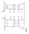
- FIG. 3 shows on the left a pipe stub 42 which is to be connected to an intermediate piece 51.
- a raw pipe 43 is shown, which is to be connected to an intermediate piece 54.
- the pipe sockets 42, 43 are connected to the upper wall 11 of the distributor housing 10, not shown otherwise tightly connected. Near their upper end have the pipe socket 42, 43 a circumferential groove 40 in its outer circumference, which is designed here as a rolling groove.
- the end portion of the intermediate pieces 51, 54 facing the raw pipe 42, 43 is provided with a respective groove 50 running around in the outer circumference.
- the groove 50 is preferably a rolling groove.
- connection between the pipe socket 42 and the intermediate piece 51 and between the pipe socket 43 and the intermediate piece 54 by means of one not yet attached Nutrohrkupplung, the one ends of pipe socket 42, 43 and spacer 51, 54 bridging sealing ring and at least two arcuate coupling parts with engaging in the grooves 40 and 50 webs.
- Nutrohrkupplung By means of one or more screws or a clamping lever Nutrohrkupplung is tightened.
- the standardized connection flange 51 ', 54' forming part of the intermediate pieces 51 and 54 is visible.
- the different axial length of the intermediate pieces 51, 54 becomes clear.
- the smaller diameter intermediate piece 54 is longer than the larger diameter intermediate piece 51 to compensate for the smaller length of a smaller diameter valve compared to the larger length of a larger diameter valve so that in the assembled state of the valves 61 to 64 (see Figure 1) whose valve spindles lie on a parallel to the distribution housing 10 line.
Abstract
Description
Die vorliegende Erfindung betrifft einen Rohrverteiler, insbesondere für Heizungsanlagen, mit einem länglichen kastenförmigen Verteilergehäuse mit einer Vorlaufkammer und einer Rücklaufkammer, wobei an dem Verteilergehäuse mehrere Anschlüsse vorgesehen sind, von denen abwechselnd jeweils einer mit der Vorlaufkammer und einer mit der Rücklaufkammer in Strömungsverbindung steht und an die Zwischenstücke anschließbar sind, die an ihrem verteilerseitigen Ende passend zu den Anschlüssen ausgeführt sind und an deren anderes Ende jeweils eine Rohrleitung anschließbar ist.The present invention relates to a manifold, in particular for heating systems, with an elongated box-shaped manifold housing having a flow chamber and a return chamber, wherein on the manifold housing a plurality of terminals are provided, of which alternately in fluid communication with the first one and the return chamber and at the intermediate pieces are connectable, which are designed at their distributor-side end to match the terminals and at the other end in each case a pipe can be connected.
Aus
Dieser bekannte Rohrverteiler ist zwar hinsichtlich der anzuschließenden Rohrleitungen bezüglich deren Durchmesser variabel verwendbar, jedoch erfordert die Herstellung von Flanschverbindungen einen relativ großen Arbeitsaufwand, da jede Flanschverbindung über ihren Umfang verteilt mehrere Schrauben und gegebenenfalls auch noch Schraubenmuttern erfordert, die jeweils angebracht und festgezogen werden müssen. Hierdurch werden relativ lange Montagezeiten verursacht.Although this known pipe distributor is variably usable with regard to the diameter of the pipes to be connected, the production of flange connections requires a relatively large amount of work, since each flange joint, distributed over its circumference, requires a plurality of screws and optionally also nuts, which must be attached and tightened in each case. This causes relatively long assembly times.
Aus
Auch dieser Rohrverteiler ist hinsichtlich des Durchmessers der anzuschließenden Rohrleitungen variabel einsetzbar, jedoch erfordert die Herstellung der Rohrleitungsanschlüsse und der Reduzierstücke aufgrund der daran anzubringenden Innengewinde und Außengewinde einen hohen Fertigungsaufwand, der zu entsprechend hohen Kosten für den Rohrleitungsverteiler führt.Also, this manifold is variable in terms of the diameter of the pipes to be connected, However, the production of the pipe connections and the reducers requires due to the internal thread and external thread to be mounted on a high production cost, which leads to a correspondingly high cost of the manifold.
Aus
Auch dieser Rohrverteiler ist hinsichtlich des Durchmessers der daran anzuschließenden Rohrleitungen variabel einsetzbar, wobei aber auch hier ein relativ hoher Arbeitsaufwand insbesondere für das Anbringen der Durchbrechungen erforderlich ist. Zudem wird für das Anbringen der Durchbrechungen ein geeignetes Werkzeug, z. B. ein Plasmaschneidgerät, benötigt.Also, this manifold is used variably in terms of the diameter of the pipes to be connected, but also here a relatively high workload is required in particular for attaching the openings. In addition, for attaching the openings a suitable tool, eg. As a plasma cutting device needed.
Für die vorliegende Erfindung stellt sich die Aufgabe, einen Rohrverteiler der eingangs genannten Art zu schaffen, der die vorstehend dargelegten Nachteile vermeidet und der bei einfacher und kostengünstiger Herstellung und mit einem geringen Montageaufwand eine hohe Flexibilität hinsichtlich unterschiedlicher Durchmesser der am Verteiler anzuschließenden Rohrleitungen aufweist.For the present invention, the object is to provide a manifold of the type mentioned above, which avoids the disadvantages set out above and has a simple and cost-effective production and low installation costs a high degree of flexibility with respect to different diameters to be connected to the manifold piping.
Die Lösung dieser Aufgabe gelingt erfindungsgemäß mit einem Rohrverteiler der eingangs genannten Art, der dadurch gekennzeichnet ist,
- daß die Anschlüsse am Verteilergehäuse als Rohrstutzen mit jeweils einer nahe ihrem verteilerfernen Ende umlaufenden Nut in ihrem Außenumfang ausgeführt sind,
- daß die Zwischenstücke verteilerseitig jeweils einen Rohrabschnitt mit jeweils einer nahe seinem verteilerseitigen Ende umlaufenden Nut in seinem Außenumfang aufweisen und
- daß jeweils ein Rohrstutzen und ein Zwischenstück mittels einer Nutrohrkupplung dicht und lösbar miteinander verbindbar sind.
- in that the connections on the distributor housing are designed as pipe sockets, each with a circumferential groove in its outer circumference, near its distributor-remote end,
- that the intermediate pieces distributor side each have a pipe section, each with a circumferential groove near its distributor end in its outer periphery and
- that in each case a pipe socket and an intermediate piece by means of a Nutrohrkupplung are tightly and detachably connected to each other.
Sowohl die Rohrstutzen, die die Anschlüsse bilden, als auch die mit den Rohrstutzen zu verbindenden Zwischenstücke sind technisch einfache Bauteile, da sie für die Herstellung der Verbindung an ihrem Verbindungsende lediglich mit einer umlaufenden Nut in ihrem Außenumfang versehen werden müssen. Die mit jeweils einer Nut versehenen Rohrstutzen einerseits und Zwischenstücke andererseits sind mittels der Nutrohrkupplung sehr schnell und einfach und dadurch zeit- und kostensparend miteinander verbindbar, was einen niedrigen Montageaufwand und dadurch einen schnelleren Montagefortschritt bedeutet. Im Vergleich zum Anbringen von Gewinden oder zum Erzeugen von Ausschnitten und/oder Schweißverbindungen ist das Anbringen von Nuten und einer Nutrohrkupplung deutlich schneller zu bewerkstelligen. Gleichzeitig bleibt eine hohe Flexibilität erhalten, weil noch vor Ort auf der Baustelle der dort tätige Handwerker auswählen und festlegen kann, welches Zwischenstück an welchen Rohrstutzen angesetzt werden soll, um einen passenden Übergang zu den weiterführenden Rohrleitungen zu erhalten. Die Ausführung des Rohrverteilers mit Nutrohrkupplungen ist dabei unabhängig von der Form und Lage der Vorlaufkammer und Rücklaufkammer im Verteilergehäuse. Die beiden genannten Kammern können nebeneinander mit einer vertikalen Trennwand oder übereinander mit einer horizontalen Trennwand angeordnet sein. Die Trennwand kann sowohl wellenförmig als auch flach ausgeführt sein.Both the pipe socket, which form the connections, as well as to be connected to the pipe socket spacers are technically simple components, since they must be provided for the preparation of the compound at its connecting end only with a circumferential groove in its outer periphery. The provided with a respective groove pipe socket on the one hand and spacers on the other hand by means of Nutrohrkupplung very quickly and easily and thereby time and cost saving connected to each other, resulting in a low installation cost and thus a means faster assembly progress. In comparison to the attachment of threads or for producing cutouts and / or welds, the attachment of grooves and a grooved pipe coupling is much faster to accomplish. At the same time, a high degree of flexibility is maintained, because even on site at the construction site, the craftsman working there can select and determine which intermediate piece is to be attached to which pipe socket, in order to obtain a suitable transition to the continuing pipelines. The design of the manifold with Nutrohrkupplungen is independent of the shape and location of the flow chamber and return chamber in the manifold housing. The two chambers mentioned can be arranged side by side with a vertical partition wall or one above the other with a horizontal partition wall. The partition can be made both wavy and flat.
Um den Rohrverteiler möglichst einfach und kostengünstig vorfertigen zu können, ohne daß dabei schon die genauen Anschlußmaße für die spätere Einbausituation feststehen müssen, wird vorgeschlagen, daß von den Anschlüssen am Verteilergehäuse mehrere oder alle untereinander einheitlich sind und daß jeweils unterschiedliche Zwischenstücke vorgesehen sind. Bei einem Heizkreisverteiler können z.B. alle Anschlüsse für die verschiedenen Heizkreise vorteilhaft untereinander einheitlich ausgeführt sein; die Kesselanschlüsse des Verteilers können anders, insbesondere größer, bemessen sein oder auch mit den Heizkreisanschlüssen übereinstimmen.In order to prefabricate the manifold as simple and inexpensive, without it being necessary to determine the exact connection dimensions for the subsequent installation situation, it is proposed that of the terminals on the distributor housing several or all are uniform with each other and that different spacers are provided. In a heating circuit distributor, e.g. all connections for the various heating circuits advantageously be carried out uniformly with each other; the boiler connections of the distributor may be different, in particular larger, or may be the same as the heating circuit connections.
Bevorzugt ist weiter vorgesehen, daß die Nuten Rollnuten sind. Rollnuten sind vergleichsweise einfach herzustellen und bieten zudem den Vorteil, daß sie nicht zu einer Materialschwächung führen, wie dies bei eingestochenen Nuten der Fall wäre. Außerdem wird beim Herstellen einer Rollnut das Material, in das die Nut eingebracht wird, sogar noch kaltverfestigt, was dessen mechanische Festigkeit vorteilhaft erhöht. Bei nicht zu großen Bauteilen besteht auch die Möglichkeit, vor Ort auf einer Baustelle die Rollnuten mittels transportabler Rollnutvorrichtungen an den Bauteilen, die miteinander verbunden werden sollen, anzubringen.Preferably, it is further provided that the grooves are rolling grooves. Rolling grooves are relatively easy to manufacture and also offer the advantage that they do not lead to a material weakening, as in the case of grooved grooves the case would be. In addition, when producing a rolling groove, the material into which the groove is introduced, even cold worked, which advantageously increases its mechanical strength. In the case of components which are not too large, it is also possible to install the rolling grooves locally on a construction site by means of transportable roll groove devices on the components which are to be connected to one another.
Weiter schlägt die Erfindung vor, daß jedes Zwischenstück an seinem verteilerfernen Ende mit einem Norm-Anschlußgewinde oder einem Norm-Anschlußflansch ausgeführt ist. In dieser Gestaltung ist der erfindungsgemäße Rohrverteiler auch in solchen Anlagen verwendbar, bei denen die weiterführenden Rohrleitungen verteilerseitig Norm-Anschlußgewinde oder -Anschlußflansche aufweisen. Selbstverständlich besteht auch die Möglichkeit, die weiterführenden Rohrleitungen mittels Nutrohrkupplungen mit den Zwischenstücken zu verbinden, was insbesondere bei der Errichtung von neuen Anlagen vorteilhaft ist.Next, the invention proposes that each intermediate piece is designed at its distributor remote end with a standard connection thread or a standard connection flange. In this design, the manifold according to the invention can also be used in such systems in which the further-running pipelines on the distributor side have standard connection threads or connection flanges. Of course, there is also the possibility of connecting the continuing pipelines by means of grooved pipe couplings with the intermediate pieces, which is particularly advantageous in the construction of new facilities.
Zur Erzielung einer Durchmesserreduzierung vom Anschluß am Rohrverteiler zur weiterführenden Rohrleitung kann das Zwischenstück ein Reduzierstück sein, dessen verteilerfernes Ende einen kleineren Nenndurchmesser als sein verteilernahes Ende hat.To achieve a reduction in diameter from the connection to the manifold to the secondary pipeline, the intermediate piece may be a reducer whose distributor remote end has a smaller nominal diameter than its distributor near end.
Alternativ kann statt dessen auch die Nutrohrkupplung eine Reduzierkupplung sein. Diese Ausgestaltung hat den spezifischen Vorteil, daß sie mit einer geringeren Baulänge auskommt, was insbesondere bei beengten Einbauverhältnissen für den Rohrverteiler von Vorteil ist.Alternatively, instead, the grooved pipe coupling may be a reducing coupling. This embodiment has the specific advantage that it manages with a smaller overall length, which is particularly advantageous in cramped installation conditions for the manifold.
Weiterhin besteht die Möglichkeit, daß in das Zwischenstück ein Ventil integriert ist. Auf diese Weise wird der vom Zwischenstück eingenommene Bauraum gleichzeitig für die Unterbringung eines in den meisten Fällen ohnehin erforderlichen Ventils genutzt.Furthermore, there is the possibility that a valve is integrated in the intermediate piece. In this way, the used by the intermediate piece space used at the same time for the accommodation of a valve required in most cases anyway.
Alternativ wird vorgeschlagen, daß mit dem Zwischenstück ein Ventil verflanscht ist. In dieser Ausgestaltung können Standardventile verwendet werden.Alternatively, it is proposed that a valve is flanged with the intermediate piece. In this embodiment, standard valves can be used.
Insbesondere zur Erzielung eines ordentlichen Anlagenbildes ist dabei weiter vorgesehen, daß die mit einem Ventil verflanschten Zwischenstücke mit einer solchen Länge ausgeführt sind, daß im montierten Zustand der Zwischenstücke und der Ventile die Spindelachsen der Ventile auf einer Linie parallel zum Verteilergehäuse zu liegen kommen.In particular, to achieve a proper plant image is further provided that the flanged with a valve spacers are designed with such a length that come in the assembled state of the spacers and valves, the spindle axes of the valves lie on a line parallel to the distributor housing.
Für den erfindungsgemäßen Rohrverteiler ist weiter bevorzugt vorgesehen, daß jede Nutrohrkupplung einen die einander zugewandten Enden von Rohrstutzen und Rohrabschnitt des Zwischenstücks übergreifenden Dichtring sowie wenigstens zwei schellenartig die einander zugewandten Enden von Rohrstutzen und Rohrabschnitt mitsamt Dichtring umgreifende, mit radial nach innen weisenden Stegen in die Nuten eingreifende, bogenförmige Kupplungsteile, die über Schrauben oder einen Spannhebel miteinander lösbar verbindbar sind, umfaßt. Eine so ausgeführte Nutrohrkupplung benötigt nur wenige Einzelteile, die schnell und einfach zur Kupplung zusammenfügbar und an dem Rohrstutzen und dem Zwischenstück festlegbar sind. Bei einer Ausführung mit Spannhebel kann sogar ganz auf Schrauben und Schraubwerkzeuge verzichtet werden und es kann ein rein manuelles Befestigen und Lösen der Nutrohrkupplung erfolgen.For the pipe manifold according to the invention is further preferably provided that each Nutrohrkupplung a mutually facing ends of pipe socket and pipe section of the intermediate piece sealing ring and at least two clamp-like the mutually facing ends of pipe socket and pipe section together with sealing ring encompassing, with radially inwardly facing webs into the grooves engaging, arcuate coupling parts, which are detachably connectable to each other via screws or a clamping lever comprises. A so executed Nutrohrkupplung requires only a few items that are quickly and easily assembled to the coupling and secured to the pipe socket and the adapter. In a version with clamping lever can even be completely dispensed with screws and screwing and it can be done purely manual fastening and loosening the Nutrohrkupplung.
Schließlich ist für den erfindungsgemäßen Rohrverteiler noch bevorzugt vorgesehen, daß das Verteilergehäuse aus miteinander verschweißten Stahlblech- und/oder Stahlprofilzuschnitten besteht, daß die Rohrstutzen mit dem Verteilergehäuse verschweißte Stahlrohrabschnitte sind und daß die Zwischenstücke einstückig aus Stahl oder aus miteinander verschweißten Einzelteilen aus Stahl bestehen. Auf diese Weise kann für den Rohrverteiler ein relativ preisgünstiges Material eingesetzt werden und es wird eine ausreichende Stabilität und Dauerhaltbarkeit gewährleistet. Bei besonders hohen Ansprüchen an die Korrosionsfestigkeit können die Teile des Rohrverteilers auch mit einer Beschichtung, z.B. Verzinkung oder Kunststoffbeschichtung, ausgeführt werden.Finally, it is preferably provided for the pipe manifold according to the invention, that the distributor housing made of welded together steel sheet and / or steel profile blanks There is that the pipe socket are welded to the distributor housing steel pipe sections and that the intermediate pieces in one piece from steel or from each other welded steel parts. In this way, a relatively inexpensive material can be used for the manifold and it is ensured sufficient stability and durability. For particularly high demands on the corrosion resistance, the parts of the manifold can also be performed with a coating, such as galvanizing or plastic coating.
Im folgenden wird ein Ausführungsbeispiel des Rohrverteilers gemäß Erfindung anhand einer Zeichnung erläutert. Die Figuren in der Zeichnung zeigen:
Figur 1- einen Rohrverteiler in Ansicht,
Figur 2- den Rohrverteiler aus
Figur 1 in Draufsicht und - Figur 3
- zwei Anschlüsse des Rohrverteilers mit jeweils einem Zwischenstück, in Ansicht.
- FIG. 1
- a manifold in view,
- FIG. 2
- the manifold of Figure 1 in plan view and
- FIG. 3
- two connections of the manifold, each with an intermediate piece, in view.
Der Rohrverteiler 1 gemäß Figur 1 umfaßt ein längliches, kastenförmiges Verteilergehäuse 10, das in seiner Einsatzstellung horizontal verläuft, wie in Figur 1 gezeigt. Das Verteilergehäuse ist im Querschnitt gesehen vorzugsweise rechteckig oder quadratisch. Das Innere des Verteilergehäuses 10 ist durch eine in Figur 1 nicht sichtbare Trennwand in zwei Kammern, nämlich eine Vorlaufkammer und eine Rücklaufkammer unterteilt.The
An der in Figur 1 oberen Wand 11 des Verteilgehäuses 10 sind mehrere, hier insgesamt acht Anschlüsse in Form von Rohrstutzen 42 und 43 angebracht. Im Inneren des Verteilergehäuses 10 sind dabei die Rohrstutzen 42 jeweils mit der Vorlaufkammer und die Rohrstutzen 43 jeweils mit der Rücklaufkammer strömungsmäßig verbunden.On the
Die in Figur 1 ganz links angeordneten beiden ersten Rohrstutzen 42 und 43 haben einen großen Durchmesser und dienen zum Anschluß beispielsweise eines Heizkesselvorlaufs und -rücklaufs einer Heizungsanlage.The leftmost in Figure 1 arranged two
Die nach rechts folgenden sechs weiteren Rohrstutzen 42, 43 sind untereinander identisch, das heißt mit gleichem Durchmesser und gleicher Länge ausgeführt. Sie dienen z.B. zum Anschluß mehrerer Heizkreise einer Heizungsanlage.The following six
Alle Rohrstutzen 42, 43 sind fest und dicht mit der oberen Wand 11 des Verteilergehäuses 10 verbunden, üblicherweise verschweißt.All
Mit jedem Rohrstutzen 42, 43 ist jeweils ein Zwischenstück 51, 52, 53 oder 54 verbunden. Die Verbindung zwischen den Zwischenstücken 51 bis 54 einerseits und den Rohrstutzen 42, 43 andererseits erfolgt hier mittels je einer Nutrohrkupplung 7.With each
Für die Verbindung mittels der Nutrohrkupplungen 7 benötigen die Rohrstutzen 42, 43 und die Zwischenstücke 51 bis 54 jeweils an ihrem Verbindungsende eine im Außenumfang umlaufende Nut, in die die Nutrohrkupplungen 7 im montierten Zustand eingreifen und so für eine ausreichend feste mechanische Verbindung sorgen. Ein einen Teil der Nutrohrkupplung 7 bildender Dichtring sorgt für die nötige Dichtigkeit der Verbindung. Die Nutrohrkupplungen 7 sind sehr schnell anbringbar und bei Bedarf wieder lösbar.For the connection by means of the
Wie die Figur 1 verdeutlicht, sind die Zwischenstücke 51 bis 54 unterschiedlich ausgestaltet. Die beiden in Figur 1 links angeordneten Zwischenstücke 51 für den Heizkesselvorlauf und -rücklauf haben einen großen und über ihre Länge konstanten Durchmesser, der zum Durchmesser der zugehörigen Rohrstutzen 42 und 43 paßt.As FIG. 1 illustrates, the
Die beiden nach rechts folgenden Zwischenstücke 52 haben einen kleineren, ebenfalls über die Länge konstanten Durchmesser, der zu den zugehörigen beiden Rohrstutzen 42 und 43 paßt.The two following to the right
Die nach rechts folgenden zwei Zwischenstücke 53 haben zwar an ihrem verteilerseitigen Ende den gleichen Durchmesser wie die links davon liegenden zwei Zwischenstücke 52, sind jedoch in ihrem Verlauf konisch und haben deshalb an ihrem verteilerfernen Ende einen kleineren Durchmesser.Although the two
Die beiden ganz rechts angeordneten Zwischenstücke 54 sind ähnlich wie die Zwischenstücke 53 ausgeführt, jedoch mit einer noch stärkeren Konizität. Hierdurch wird das verteilerferne Ende der Zwischenstücke 54 auf einen noch kleineren Durchmesser gebracht, als dies bei den benachbarten Zwischenstücken 53 der Fall ist.The two
Die in Figur 1 von rechts her gesehen ersten sechs Rohrstutzen 42, 43 sind untereinander identisch, können aber mit unterschiedlichen Zwischenstücken 52 bis 54 verbunden werden, um auf einen passenden Durchmesser für die hier nicht dargestellten weiterführenden Rohrleitungen zu kommen. Der Durchmesser der anzuschließenden Rohrleitungen muß dabei vorteilhaft bei der Fertigung des Verteilergehäuses 10 noch nicht bekannt sein; vielmehr kann noch auf der Baustelle beim Einbau des Rohrverteilers 1 das jeweils passende Zwischenstück 52 bis 54 ausgewählt und in der erforderlichen Position mit dem zugehörigen Rohrstutzen 42 bzw. 43 schnell und einfach mittels der Nutrohrkupplungen 7 verbunden werden.The first seen in Figure 1 from the first six
Weiter sind bei dem in Figur 1 gezeigten Ausführungsbeispiel mit den Zwischenstücken 51 bis 54 Ventile 61 bis 64 verbunden, hier über Flansche 51', 52', 53'und 54' verflanscht. Dabei haben die Ventile 61 bis 64 je nach ihrem Nenndurchmesser eine unterschiedliche Baulänge. Um dennoch eine Lage aller Ventilspindeln der Ventile 61 bis 64 auf einer geraden, zur oberen Wand 11 des Verteilergehäuses 10 parallelen Linie zu erreichen, sind die Zwischenstücke 51 bis 54 mit entsprechend unterschiedlicher Länge ausgeführt. Dabei sind die Zwischenstücke mit dem größeren Durchmesser kürzer und die Zwischenstücke mit dem kleineren Durchmesser am verteilerfernen Ende länger ausgeführt, um die entgegengesetzten Längenunterschiede der Ventile 61 bis 64 auszugleichen.Further, in the embodiment shown in Figure 1 with the
An der Unterseite des Verteilergehäuses 10 sind mit deren unterer Wand 12 hier noch zwei Standfüße 80 verbunden, die der Aufstellung des Rohrverteilers 1 auf einem Fußboden dienen. Außerdem sind hier unterseitig noch zwei untere Rohrstutzen 81 am Verteilergehäuse 10 vorgesehen, die beispielsweise zur Entleerung der beiden Kammern des Verteilergehäuses 10 dienen.At the bottom of the
Durch die strichpunktierte Linie 82 ist die äußere Begrenzung eines Isolierstoffkörpers dargestellt, der das Verteilergehäuse 10 umgibt und im Falle eines Heizungs-Rohrverteilers vor Energieverlusten schützt.The dash-dotted
Figur 2 zeigt den Rohrverteiler 1 aus Figur 1 in Draufsicht, wobei hier die obere Wand 11 "durchsichtig" ist. Auf diese Weise wird die im Inneren des Verteilergehäuses 10 liegende Trennwand 13 sichtbar, die hier einen wellenförmigen Verlauf hat. Diese wellenförmig verlaufende Trennwand 13 unterteilt das Innere des Verteilergehäuses 10 in die schon erwähnte Vorlaufkammer 2 einerseits und Rücklaufkammer 3 andererseits.Figure 2 shows the
Wie in Figur 2 nun deutlich erkennbar ist, münden die Rohrstutzen 42 sämtlich in die Vorlaufkammer 2, während die Rohrstutzen 43 sämtlich in die Rücklaufkammer 3 münden. Durch den wellenförmigen Verlauf der Trennwand 13 können dabei die Rohrstutzen 42, 43 auf einer einzigen geraden Linie auf der Oberseite des Verteilergehäuses 10 angeordnet werden.As can now be clearly seen in FIG. 2, the
Mit den Rohrstutzen 42, 43 sind wieder die Zwischenstücke 51 bis 54 verbunden, während in Figur 2 die Ventile 61 bis 64 weggelassen sind. Damit fällt in Figur 2 der Blick des Betrachters auf die Anschlußflansche 51' bis 54' der Zwischenstücke 51 bis 54.With the
Durch die strichpunktierte Linie 82 ist wieder die äußere Kontur eines das Verteilergehäuse 10 umgebenden Isolierstoffkörpers angedeutet.The dash-dotted
Figur 3 zeigt links einen Rohrstutzen 42, der mit einem Zwischenstück 51 zu verbinden ist. Rechts in Figur 3 ist ein Rohstutzen 43 gezeigt, der mit einem Zwischenstück 54 zu verbinden ist.FIG. 3 shows on the left a
Die Rohrstutzen 42, 43 sind mit der oberen Wand 11 des im übrigen nicht dargestellten Verteilergehäuses 10 dicht verbunden. Nahe ihrem oberen Ende besitzen die Rohrstutzen 42, 43 eine in deren Außenumfang umlaufende Nut 40, die hier als Rollnut ausgeführt ist.The
In gleicher Art und Weise ist jeweils der den Rohstutzen 42, 43 zugewandte Endbereich der hier dargestellten Zwischenstücke 51, 54 mit je einer im Außenumfang umlaufenden Nut 50 versehen. Auch hier ist die Nut 50 bevorzugt eine Rollnut.In the same way, in each case the end portion of the
Die Verbindung zwischen dem Rohrstutzen 42 und dem Zwischenstück 51 sowie zwischen dem Rohrstutzen 43 und dem Zwischenstück 54 erfolgt mittels je einer hier noch nicht angebrachten Nutrohrkupplung, die einen die Enden von Rohrstutzen 42, 43 und Zwischenstück 51, 54 überbrückenden Dichtring sowie wenigstens zwei bogenförmige Kupplungsteile mit in die Nuten 40 und 50 eingreifenden Stegen umfaßt. Mittels einer oder mehrerer Schrauben oder eines Spannhebels wird die Nutrohrkupplung festgezogen.The connection between the
Ganz oben in Figur 3 ist jeweils der einen Teil der Zwischenstücke 51 und 54 bildende genormte Anschlußflansch 51', 54' sichtbar. Hier wird auch die unterschiedliche axiale Länge der Zwischenstücke 51, 54 deutlich. Das Zwischenstück 54 mit dem kleineren Durchmesser ist länger als das Zwischenstück 51 mit dem größeren Durchmesser, um die kleinere Länge eines Ventils für einen kleineren Durchmesser im Vergleich zur größeren Länge eines Ventils für einen größeren Durchmesser so auszugleichen, daß im angebauten Zustand der Ventile 61 bis 64 (siehe Figur 1) deren Ventilspindeln auf einer zum Verteilgehäuse 10 parallelen Linie liegen.At the top of FIG. 3, the standardized connection flange 51 ', 54' forming part of the
Claims (11)
dadurch gekennzeichnet,
characterized,
Applications Claiming Priority (1)
| Application Number | Priority Date | Filing Date | Title |
|---|---|---|---|
| DE200520003778 DE202005003778U1 (en) | 2005-03-09 | 2005-03-09 | Pipe distributors, in particular for heating systems |
Publications (2)
| Publication Number | Publication Date |
|---|---|
| EP1701097A2 true EP1701097A2 (en) | 2006-09-13 |
| EP1701097A3 EP1701097A3 (en) | 2007-10-10 |
Family
ID=34745634
Family Applications (1)
| Application Number | Title | Priority Date | Filing Date |
|---|---|---|---|
| EP06003660A Withdrawn EP1701097A3 (en) | 2005-03-09 | 2006-02-23 | Manifold esp. for heating installations |
Country Status (2)
| Country | Link |
|---|---|
| EP (1) | EP1701097A3 (en) |
| DE (1) | DE202005003778U1 (en) |
Cited By (2)
| Publication number | Priority date | Publication date | Assignee | Title |
|---|---|---|---|---|
| DE102007016960A1 (en) * | 2007-04-05 | 2008-10-09 | Kermi Gmbh | Device for the inflow of heating medium in a radiator |
| EP2157375A3 (en) * | 2008-08-20 | 2014-12-31 | Comfort-Sinusverteiler GmbH | Hydraulic points for a heating assembly and cascade unit for a heating assembly |
Families Citing this family (4)
| Publication number | Priority date | Publication date | Assignee | Title |
|---|---|---|---|---|
| GB2480669A (en) * | 2010-05-27 | 2011-11-30 | Zonealone Ltd | Manifold for a heating or refrigeration system |
| JP2014145532A (en) * | 2013-01-29 | 2014-08-14 | Mitsubishi Electric Corp | Heat medium use device |
| DE102015117997A1 (en) | 2015-10-22 | 2017-04-27 | Viessmann Werke Gmbh & Co Kg | manifold |
| DE102016115417A1 (en) | 2016-08-19 | 2018-02-22 | Viessmann Werke Gmbh & Co Kg | heating system |
Citations (3)
| Publication number | Priority date | Publication date | Assignee | Title |
|---|---|---|---|---|
| DE3012854A1 (en) | 1980-04-02 | 1981-10-08 | Maile + Grammer Gmbh, 7407 Rottenburg | PIPELINE DISTRIBUTORS, ESPECIALLY FOR HOT WATER HEATERS |
| EP0415260B1 (en) | 1989-08-30 | 1994-03-30 | Strawa Metallverarbeitungs GmbH | Heating and/or boiler distributor |
| DE20010701U1 (en) | 2000-06-15 | 2001-10-31 | Comfort Sinusverteiler Gmbh & | Pipe distributor, especially for heating systems |
Family Cites Families (3)
| Publication number | Priority date | Publication date | Assignee | Title |
|---|---|---|---|---|
| DE29702573U1 (en) * | 1997-02-14 | 1997-08-28 | Maatz Alfons | Device for distributing and collecting liquid media, in particular supply and return distributors of heating water |
| US6626466B1 (en) * | 1999-08-05 | 2003-09-30 | Victaulic Company Of America | Anti-mismatch or near-sized coupling segments |
| FI115485B (en) * | 2001-07-06 | 2005-05-13 | Uponor Innovation Ab | Branch piece for piping |
-
2005
- 2005-03-09 DE DE200520003778 patent/DE202005003778U1/en not_active Expired - Lifetime
-
2006
- 2006-02-23 EP EP06003660A patent/EP1701097A3/en not_active Withdrawn
Patent Citations (3)
| Publication number | Priority date | Publication date | Assignee | Title |
|---|---|---|---|---|
| DE3012854A1 (en) | 1980-04-02 | 1981-10-08 | Maile + Grammer Gmbh, 7407 Rottenburg | PIPELINE DISTRIBUTORS, ESPECIALLY FOR HOT WATER HEATERS |
| EP0415260B1 (en) | 1989-08-30 | 1994-03-30 | Strawa Metallverarbeitungs GmbH | Heating and/or boiler distributor |
| DE20010701U1 (en) | 2000-06-15 | 2001-10-31 | Comfort Sinusverteiler Gmbh & | Pipe distributor, especially for heating systems |
Cited By (3)
| Publication number | Priority date | Publication date | Assignee | Title |
|---|---|---|---|---|
| DE102007016960A1 (en) * | 2007-04-05 | 2008-10-09 | Kermi Gmbh | Device for the inflow of heating medium in a radiator |
| DE102007016960B4 (en) * | 2007-04-05 | 2010-04-01 | Kermi Gmbh | Device for the inflow of heating medium in a radiator |
| EP2157375A3 (en) * | 2008-08-20 | 2014-12-31 | Comfort-Sinusverteiler GmbH | Hydraulic points for a heating assembly and cascade unit for a heating assembly |
Also Published As
| Publication number | Publication date |
|---|---|
| DE202005003778U1 (en) | 2005-07-07 |
| EP1701097A3 (en) | 2007-10-10 |
Similar Documents
| Publication | Publication Date | Title |
|---|---|---|
| DE102009052674A1 (en) | Device for connecting double-walled pipes | |
| EP1701097A2 (en) | Manifold esp. for heating installations | |
| EP2955287A1 (en) | Connection device and use of same for a sanitary installation | |
| DE102007010116B4 (en) | Hot water distributor of a floor heating system and method for producing a distributor pipe of the hot water distributor | |
| DE102006034101A1 (en) | Sleeve and combination of sleeve with pressing tool | |
| EP0876564B1 (en) | Pipe connecting device | |
| DE3214775C2 (en) | Device for transferring heat-carrying fluid from a supply line of a district heating power plant to a consumer | |
| EP1690486A2 (en) | Shower installation | |
| DE3132602A1 (en) | RADIATOR | |
| EP3601922A1 (en) | Connecting array and joining array for plate heat exchangers | |
| DE19901990C2 (en) | Press fitting | |
| DE19637575B4 (en) | Distribution station for a heating system | |
| EP0217321A2 (en) | Shut-off valve | |
| EP2716980A2 (en) | Pipe manifold system | |
| AT506991B1 (en) | CONNECTOR | |
| DE202015101027U1 (en) | Connector with two flanges for connection of water treatment devices and associated connection arrangement | |
| DE102015203854B4 (en) | Connection arrangement for the treatment of water in a water network | |
| AT222853B (en) | Connector for pipes | |
| DE19710509A1 (en) | Distributor array for panel radiator | |
| WO1998036201A1 (en) | Device for distributing and collecting liquid media | |
| EP2023058B1 (en) | Connecting piece for the fluid circulation with inner circulation pipe for a service water or heating water supply facility, pipe assembly with such a connecting piece and method for assembling such a pipe assembly | |
| DE19511537A1 (en) | Component for a hydraulic or pneumatic system and for fluids in general, for example a tap, a row fitting, a corner fitting, a 3-way or multi-way fitting | |
| DE102006013002A1 (en) | Fluid line connection for use in e.g. brake system, has fluid line secured in base in form fit manner by retaining unit, where retaining unit is assembled in and/or on base in direction running perpendicular to connecting surface | |
| DE102005008833B4 (en) | The fluid distributor | |
| WO2002061325A1 (en) | Distributor for flowing media |
Legal Events
| Date | Code | Title | Description |
|---|---|---|---|
| PUAI | Public reference made under article 153(3) epc to a published international application that has entered the european phase |
Free format text: ORIGINAL CODE: 0009012 |
|
| AK | Designated contracting states |
Kind code of ref document: A2 Designated state(s): AT BE BG CH CY CZ DE DK EE ES FI FR GB GR HU IE IS IT LI LT LU LV MC NL PL PT RO SE SI SK TR |
|
| AX | Request for extension of the european patent |
Extension state: AL BA HR MK YU |
|
| PUAL | Search report despatched |
Free format text: ORIGINAL CODE: 0009013 |
|
| AK | Designated contracting states |
Kind code of ref document: A3 Designated state(s): AT BE BG CH CY CZ DE DK EE ES FI FR GB GR HU IE IS IT LI LT LU LV MC NL PL PT RO SE SI SK TR |
|
| AX | Request for extension of the european patent |
Extension state: AL BA HR MK YU |
|
| AKX | Designation fees paid | ||
| STAA | Information on the status of an ep patent application or granted ep patent |
Free format text: STATUS: THE APPLICATION IS DEEMED TO BE WITHDRAWN |
|
| 18D | Application deemed to be withdrawn |
Effective date: 20080411 |
|
| REG | Reference to a national code |
Ref country code: DE Ref legal event code: 8566 |