EP0415260B1 - Heating and/or boiler distributor - Google Patents
Heating and/or boiler distributor Download PDFInfo
- Publication number
- EP0415260B1 EP0415260B1 EP90116105A EP90116105A EP0415260B1 EP 0415260 B1 EP0415260 B1 EP 0415260B1 EP 90116105 A EP90116105 A EP 90116105A EP 90116105 A EP90116105 A EP 90116105A EP 0415260 B1 EP0415260 B1 EP 0415260B1
- Authority
- EP
- European Patent Office
- Prior art keywords
- flanges
- pipe
- connecting pieces
- crowns
- heating
- Prior art date
- Legal status (The legal status is an assumption and is not a legal conclusion. Google has not performed a legal analysis and makes no representation as to the accuracy of the status listed.)
- Expired - Lifetime
Links
- 238000010438 heat treatment Methods 0.000 title claims description 5
- 238000010276 construction Methods 0.000 claims description 3
- 238000009434 installation Methods 0.000 claims description 2
- 239000003638 chemical reducing agent Substances 0.000 description 2
- 238000004519 manufacturing process Methods 0.000 description 1
Images
Classifications
-
- F—MECHANICAL ENGINEERING; LIGHTING; HEATING; WEAPONS; BLASTING
- F24—HEATING; RANGES; VENTILATING
- F24D—DOMESTIC- OR SPACE-HEATING SYSTEMS, e.g. CENTRAL HEATING SYSTEMS; DOMESTIC HOT-WATER SUPPLY SYSTEMS; ELEMENTS OR COMPONENTS THEREFOR
- F24D3/00—Hot-water central heating systems
- F24D3/10—Feed-line arrangements, e.g. providing for heat-accumulator tanks, expansion tanks ; Hydraulic components of a central heating system
- F24D3/1058—Feed-line arrangements, e.g. providing for heat-accumulator tanks, expansion tanks ; Hydraulic components of a central heating system disposition of pipes and pipe connections
- F24D3/1066—Distributors for heating liquids
- F24D3/1075—Built up from modules
-
- F—MECHANICAL ENGINEERING; LIGHTING; HEATING; WEAPONS; BLASTING
- F16—ENGINEERING ELEMENTS AND UNITS; GENERAL MEASURES FOR PRODUCING AND MAINTAINING EFFECTIVE FUNCTIONING OF MACHINES OR INSTALLATIONS; THERMAL INSULATION IN GENERAL
- F16L—PIPES; JOINTS OR FITTINGS FOR PIPES; SUPPORTS FOR PIPES, CABLES OR PROTECTIVE TUBING; MEANS FOR THERMAL INSULATION IN GENERAL
- F16L25/00—Constructive types of pipe joints not provided for in groups F16L13/00 - F16L23/00 ; Details of pipe joints not otherwise provided for, e.g. electrically conducting or insulating means
- F16L25/14—Joints for pipes of different diameters or cross-section
-
- F—MECHANICAL ENGINEERING; LIGHTING; HEATING; WEAPONS; BLASTING
- F16—ENGINEERING ELEMENTS AND UNITS; GENERAL MEASURES FOR PRODUCING AND MAINTAINING EFFECTIVE FUNCTIONING OF MACHINES OR INSTALLATIONS; THERMAL INSULATION IN GENERAL
- F16L—PIPES; JOINTS OR FITTINGS FOR PIPES; SUPPORTS FOR PIPES, CABLES OR PROTECTIVE TUBING; MEANS FOR THERMAL INSULATION IN GENERAL
- F16L41/00—Branching pipes; Joining pipes to walls
- F16L41/02—Branch units, e.g. made in one piece, welded, riveted
- F16L41/03—Branch units, e.g. made in one piece, welded, riveted comprising junction pieces for four or more pipe members
-
- F—MECHANICAL ENGINEERING; LIGHTING; HEATING; WEAPONS; BLASTING
- F24—HEATING; RANGES; VENTILATING
- F24D—DOMESTIC- OR SPACE-HEATING SYSTEMS, e.g. CENTRAL HEATING SYSTEMS; DOMESTIC HOT-WATER SUPPLY SYSTEMS; ELEMENTS OR COMPONENTS THEREFOR
- F24D3/00—Hot-water central heating systems
- F24D3/10—Feed-line arrangements, e.g. providing for heat-accumulator tanks, expansion tanks ; Hydraulic components of a central heating system
- F24D3/1058—Feed-line arrangements, e.g. providing for heat-accumulator tanks, expansion tanks ; Hydraulic components of a central heating system disposition of pipes and pipe connections
- F24D3/1066—Distributors for heating liquids
Definitions
- the invention relates to a heating or boiler manifold, made up of modular prefabricated basic housing units and with a plurality of fixed outlet connections of the same nominal size, primarily for large systems.
- a distributor in which the outgoing line connections as lying in a row, frustoconical pipe sockets are formed; Markings are placed on the lateral surface of the line connections at predetermined longitudinal intervals, the position of which is matched to the cone angle of the line connections.
- the coordination is chosen so that when a pipe socket is cut to length along a marking, there is such a residual height of the pipe socket and at the upper end such an opening cross section that when the pump or a valve with standardized dimensions (overall height and connection cross section) is fitted, the actuating member or the Center of this device is at the same height above the distributor housing as when placing a correspondingly smaller device on the pipe stub that has not been cut to length.
- the pipe sockets are higher, their opening cross-section is smaller and so matched to the connection cross-section of the device to be attached that the overall height of the device from the connection point to the central height or operating level of the device is again the same overall height as for a larger one, attached to the cut-off pipe socket Device results.
- an extremely expedient and fail-safe installation of the pipe distributor can be achieved.
- On the outer ends of the Pipe sockets can be welded onto either connecting flanges or connecting threads.
- the invention is therefore also based on the object of providing a pipe distributor in which the line connections branching off from the flow space and the return space are aligned with one another in the longitudinal direction, which is suitable for large nominal widths in manufacture and is therefore inexpensive and to the full extent in the workshop can be prefabricated.
- the new distributor consists of a housing 1 of any length and is provided with any number of outlets 2 already fixed in the workshop and one and the same nominal nominal width "NW1"; It can be advantageous if the housing-side outlets 2 are designed as flange-free flange rings 2, directly welded onto the top of the housing la, in such a way that they have the same height "h” industrial flanges, ie special flanges with a smaller outside diameter "d" than that "D” of Represent DIN flanges 3 of the same nominal size "NW1".
- the pipe attachments 4, reducers 5 or the like to be connected to these outlets 2 on the construction site each also have corresponding special flanges 4a and 5a on the foot side and also, also prefabricated in the workshop, have an overall height of "H 1 or H 2", which means that Standard flanges 3 or 6 connected fittings or the like brings to the same average spindle height "Sp".
- the new system is completed by the fact that the special flanges 4a and 5a with their top or reducers 4 or 5 are formed in one piece and are connected to the outlets 2 by screws 7, preferably the upper flanges 4a and 5a through holes 8 and the associated counter flanges of Outlets 2 threaded holes 9.
- the present invention now also makes it possible for large distributors with a large number of outlets 2 to produce them in a simple manner and to complete them directly on site without reworking; this considerably simplifies planning work and storage.
Landscapes
- Engineering & Computer Science (AREA)
- General Engineering & Computer Science (AREA)
- Mechanical Engineering (AREA)
- Physics & Mathematics (AREA)
- Thermal Sciences (AREA)
- Chemical & Material Sciences (AREA)
- Combustion & Propulsion (AREA)
- Branch Pipes, Bends, And The Like (AREA)
- Mounting, Exchange, And Manufacturing Of Dies (AREA)
- Steam Or Hot-Water Central Heating Systems (AREA)
Abstract
Description
Die Erfindung bezieht sich auf einen aus baukastenmäßig vorgefertigten Gehäuse-Grundeinheiten und mit mehreren fest angebrachten Abgangsstutzen derselben Nennweite versehenen Heizungs- bzw. Kesselverteiler, vornehmlich für Großanlagen.The invention relates to a heating or boiler manifold, made up of modular prefabricated basic housing units and with a plurality of fixed outlet connections of the same nominal size, primarily for large systems.
Aus der DE-PS 27 41 727 ist ein Verteiler bekannt, bei dem die abgehenden Leitungsanschlüsse als in einer Reihe liegende, kegelstumpfförmige Rohrstutzen ausgebildet sind; auf der Mantelfläche der Leitungsanschlüsse sind dabei in vorbestimmten Längsabständen Markierungen angebracht, deren Lage auf den Kegelwinkel der Leitungsanschlüsse abgestimmt ist. Die Abstimmung ist so gewählt, daß beim Ablängen eines Rohrstutzens längs einer Markierung sich eine derartige restliche Höhe des Rohrstutzens und am oberen Ende ein derartiger Öffnungsquerschnitt ergibt, daß beim Aufsetzen einer Pumpe oder eines Ventiles mit genormten Abmessungen (Bauhöhe und Anschlußquerschnitt) das Betätigungsorgan oder die Mitte dieses Geräts in der gleichen Höhe über dem Verteilergehäuse liegt, wie beim Aufsetzen eines entsprechend kleineren Geräts auf die nicht abgelängten Rohrstutzen. Zwar sind die Rohrstutzen höher, jedoch ist ihr Öffnungsquerschnitt kleiner und so auf den Anschlußquerschnitt des anzusetzenden Geräts abgestimmt, daß die Bauhöhe des Geräts von der Anschlußstelle bis zur Mittelhöhe oder Betätigungsebene des Geräts wieder die gleiche Gesamthöhe wie bei einem größeren, an den abgelängten Rohrstutzen angesetzten Gerät ergibt. Durch entsprechende Wahl des Kegelwinkels und der Markierungsabstände läßt sich so eine äußerst zweckmäßige und fehlersichere Montage des Rohrverteilers erreichen. Auf die äußeren Enden des Rohrstutzens können hierbei entweder Anschlußflansche oder Anschlußgewinde aufgeschweißt sein.From DE-PS 27 41 727 a distributor is known in which the outgoing line connections as lying in a row, frustoconical pipe sockets are formed; Markings are placed on the lateral surface of the line connections at predetermined longitudinal intervals, the position of which is matched to the cone angle of the line connections. The coordination is chosen so that when a pipe socket is cut to length along a marking, there is such a residual height of the pipe socket and at the upper end such an opening cross section that when the pump or a valve with standardized dimensions (overall height and connection cross section) is fitted, the actuating member or the Center of this device is at the same height above the distributor housing as when placing a correspondingly smaller device on the pipe stub that has not been cut to length. Although the pipe sockets are higher, their opening cross-section is smaller and so matched to the connection cross-section of the device to be attached that the overall height of the device from the connection point to the central height or operating level of the device is again the same overall height as for a larger one, attached to the cut-off pipe socket Device results. By appropriate selection of the cone angle and the marking distances, an extremely expedient and fail-safe installation of the pipe distributor can be achieved. On the outer ends of the Pipe sockets can be welded onto either connecting flanges or connecting threads.
Der Nachteil bei dieser zuvor beschriebenen Ausführung liegt vor allem in den hier noch notwendigen Montagearbeiten auf der Baustelle.The disadvantage of this previously described embodiment lies above all in the assembly work still required here on the construction site.
Aus der DE-A-3 012 854 ist ein Rohrleitungsverteiler nach dem Oberbegriff des Patentanspruchs 1 bekannt. Bei diesem haben die Abgangsstutzen ein Innengewinde und die Rohraufsätze ein Außengewinde, an das sich ein Werkstück-Ansatzbereich anschließt, so daß die Rohraufsätze mittels eines Maulschlüssels oder einer Rohrzange in die Abgangsstutzen eingeschraubt werden. Dieses System ist nur für kleine Nennweiten brauchbar.From DE-A-3 012 854 a pipe distributor according to the preamble of
Der Erfindung liegt deshalb auch die Aufgabe zugrunde, einen Rohrverteiler, bei welchem die von dem Vorlaufraum und dem Rücklaufraum abzweigenden Leitungsanschlüsse in Längsrichtung miteinander fluchten, zu schaffen, der bei Eignung für große Nennweiten in der Herstellung einfach und damit preisgünstig ist und werkstattmäßig in vollem Umfang vorgefertigt werden kann.The invention is therefore also based on the object of providing a pipe distributor in which the line connections branching off from the flow space and the return space are aligned with one another in the longitudinal direction, which is suitable for large nominal widths in manufacture and is therefore inexpensive and to the full extent in the workshop can be prefabricated.
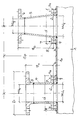
Diese Aufgabe wird bei einem Rohrverteiler der eingangs genannten Gattung erfindungsgemäß gelöst durch die Merkmale des kennzeichnenden Teils des Patentanspruchs 1. Vorteilhafte Ausführungsformen der Erfindung sind in den Unteransprüchen angegeben. Die Zeichnung zeigt einen Längsschnitt durch ein Teilstück des erfindungsgemäßen Verteilers.This object is achieved according to the invention in a pipe distributor of the type mentioned at the outset by the features of the characterizing part of
Der neue Verteiler besteht aus einem Gehäuse 1 beliebiger Länge und ist mit einer beliebigen Anzahl werkstattmäßig bereits fest angebrachter Abgangsstutzen 2 ein und derselben Grundnennweite "NW1" versehen; vorteilhaft kann es dabei sein, wenn die gehäuseseitigen Abgangsstutzen 2 als rohransatzlose, unmittelbar auf die Gehäuseoberseite la aufgeschweißte Flanschringe 2 in der Form ausgebildet sind, daß sie gleichhohe "h" Industrieflansche, also Sonderflansche mit kleinerem Außendurchmesser "d" als demjenigen "D" von DIN-Flanschen 3 gleicher Nennweite "NW1" darstellen.The new distributor consists of a
Die an diese Abgangsstutzen 2 nun jeweils auf der Baustelle anzuschließenden Rohraufsätze 4, Reduzierstücke 5 o. dgl., besitzen fußseitig ebenfalls entsprechende Sonderflansche 4a bzw. 5a und haben zudem, ebenfalls werkstattmäßig vorgefertigt, eine Bauhöhe "H₁ bzw. H₂", die daran über Normflansche 3 bzw. 6 angeschlossene Armaturen o. dgl. auf dieselbe mittlere Spindelhöhe "Sp" bringt.The pipe attachments 4,
Vervollständigt wird das neue System noch dadurch, daß die Sonderflansche 4a und 5a mit ihren Aufsatz- bzw. Reduzierstücken 4 bzw. 5 durch einstückige Ausformung gebildet und über Schrauben 7 mit den Abgangsstutzen 2 verbunden sind, wobei vorzugsweise die oberen Flansche 4a und 5a Durchgangsbohrungen 8 und die zugehörigen Gegenflansche der Abgangsstutzen 2 Gewindelöcher 9 aufweisen.The new system is completed by the fact that the
Im Gegensatz zu allen anderen bislang bekannten Ausführungen ist es durch die vorliegende Erfindung nunmehr auch für Großverteiler mit einer großen Zahl von Abgängen 2 möglich, diese auf einfache Weise herzustellen und ohne Nacharbeitung direkt auf der Baustelle zu komplettieren; hierdurch werden Planungsarbeiten und Lagerhalterung ganz erheblich vereinfacht.In contrast to all other previously known designs, the present invention now also makes it possible for large distributors with a large number of outlets 2 to produce them in a simple manner and to complete them directly on site without reworking; this considerably simplifies planning work and storage.
Claims (3)
- A heating and/or boiler distributor, in particular for large-scale installations, made of
casing basic units (1),
a plurality of exit connecting pieces (2) premounted in construction kit manner fixedly attached to the casing (1) having the same nominal diameter (NW₃) and
pipe crowns (4, 5) each coupled to a respective connecting piece,
having a connection for connecting with fittings with standardized dimensions, the pipe crowns having a mounting height (H1, H2) as a function of the opening cross-section (NW₁, NW₂) of their corresponding connection, which causes the fittings to be connected therewith to be on the same mean spindle height (Sp),
characterized in that
the exit connecting pieces (2) are formed as industrial flanges of the same height (h), therefore as special flanges with smaller outer diameters (d) than those (D) of DIN standardized flanges (3) having the same nominal diameter (NW₁), and the pipe crowns (4, 5) have at their base portions also corresponding special flanges (4a, 5a) and at the other side DIN standardized flanges (3, 6). - The heating and/or boiler distributor according to claim 1, characterized in that the special flanges (4a, 5a) are formed integrally with the corresponding pipe crowns (4, 5) and are connected by screws (7) with the exit connecting pieces (2), preferably the flanges (4a, 5a) of the pipe crowns comprise through-bores (8) and the flanges of the exit connecting pieces (2) comprise threaded holes (9).
- The heating and/or boiler distributor according to claim 1 or 2,
characterized in that the exit connecting pieces are formed as flange rings (2) being immediately welded to the casing top (1a).
Priority Applications (1)
| Application Number | Priority Date | Filing Date | Title |
|---|---|---|---|
| AT90116105T ATE103686T1 (en) | 1989-08-30 | 1990-08-22 | HEATING OR BOILER MANIFOLDS. |
Applications Claiming Priority (2)
| Application Number | Priority Date | Filing Date | Title |
|---|---|---|---|
| DE3928731A DE3928731A1 (en) | 1989-08-30 | 1989-08-30 | HEATING AND BOILER DISTRIBUTOR |
| DE3928731 | 1989-08-30 |
Publications (2)
| Publication Number | Publication Date |
|---|---|
| EP0415260A1 EP0415260A1 (en) | 1991-03-06 |
| EP0415260B1 true EP0415260B1 (en) | 1994-03-30 |
Family
ID=6388216
Family Applications (1)
| Application Number | Title | Priority Date | Filing Date |
|---|---|---|---|
| EP90116105A Expired - Lifetime EP0415260B1 (en) | 1989-08-30 | 1990-08-22 | Heating and/or boiler distributor |
Country Status (3)
| Country | Link |
|---|---|
| EP (1) | EP0415260B1 (en) |
| AT (1) | ATE103686T1 (en) |
| DE (2) | DE3928731A1 (en) |
Cited By (1)
| Publication number | Priority date | Publication date | Assignee | Title |
|---|---|---|---|---|
| EP1701097A2 (en) | 2005-03-09 | 2006-09-13 | Comfort-Sinusverteiler GmbH | Manifold esp. for heating installations |
Families Citing this family (4)
| Publication number | Priority date | Publication date | Assignee | Title |
|---|---|---|---|---|
| JPH09317599A (en) * | 1996-05-22 | 1997-12-09 | Usui Internatl Ind Co Ltd | Common rail and manufacture thereof |
| US6543811B1 (en) * | 1996-12-02 | 2003-04-08 | Robert W. Campbell | Pipe flange assembly |
| US5947528A (en) * | 1996-12-02 | 1999-09-07 | Campbell; Robert W. | Pipe flange assembly |
| JP3745211B2 (en) * | 2000-09-21 | 2006-02-15 | 柿沼金属精機株式会社 | Branch joint |
Family Cites Families (2)
| Publication number | Priority date | Publication date | Assignee | Title |
|---|---|---|---|---|
| DE2748673C2 (en) * | 1977-10-29 | 1985-07-04 | Antonio Penne Pescara Rietti | Distribution system for circulating medium |
| DE3012854A1 (en) * | 1980-04-02 | 1981-10-08 | Maile + Grammer Gmbh, 7407 Rottenburg | PIPELINE DISTRIBUTORS, ESPECIALLY FOR HOT WATER HEATERS |
-
1989
- 1989-08-30 DE DE3928731A patent/DE3928731A1/en not_active Withdrawn
-
1990
- 1990-08-22 EP EP90116105A patent/EP0415260B1/en not_active Expired - Lifetime
- 1990-08-22 DE DE90116105T patent/DE59005171D1/en not_active Expired - Fee Related
- 1990-08-22 AT AT90116105T patent/ATE103686T1/en active
Cited By (1)
| Publication number | Priority date | Publication date | Assignee | Title |
|---|---|---|---|---|
| EP1701097A2 (en) | 2005-03-09 | 2006-09-13 | Comfort-Sinusverteiler GmbH | Manifold esp. for heating installations |
Also Published As
| Publication number | Publication date |
|---|---|
| DE3928731A1 (en) | 1991-03-07 |
| ATE103686T1 (en) | 1994-04-15 |
| EP0415260A1 (en) | 1991-03-06 |
| DE59005171D1 (en) | 1994-05-05 |
Similar Documents
| Publication | Publication Date | Title |
|---|---|---|
| EP0715112A2 (en) | Device for simultaneous connection of electrovalves | |
| EP0415260B1 (en) | Heating and/or boiler distributor | |
| DE2835435C3 (en) | Spring hangers or supports, in particular for pipelines | |
| EP0092032A2 (en) | Device for transferring heat from a supply pipe to a consumer | |
| DE4107969A1 (en) | Thermostat valve lower part - has valve seat integral with housing, and has plastics sleeve with through-flow hole, and pre-setting control with flow restrictor holes | |
| DE2338671A1 (en) | EQUIPMENT SET FOR SWITCHING ON A GAS OR LIQUID LINE, IN PARTICULAR A COMPRESSED AIR LINE | |
| DE2335915C3 (en) | Device for holding and connecting devices connected in series for controlling and / or conditioning fluids | |
| EP0678675A1 (en) | Modular designed valve base for electromagnetic directional valves | |
| DE3209950A1 (en) | Flange distributor for hydraulic systems at high pressures | |
| AT404299B (en) | CONNECTION SET | |
| AT390661B (en) | Connecting device for the connection of radiators | |
| EP0866280B1 (en) | Connection adapter | |
| DE9010608U1 (en) | Motor-controlled multi-way valve | |
| AT392829B (en) | Connecting device for the connection of radiators | |
| DE3805867C2 (en) | ||
| DE29610547U1 (en) | Slider element in sheet metal construction | |
| DE29822406U1 (en) | Connection housing for a pump | |
| DE20107715U1 (en) | Multi-way and distribution valve | |
| EP3101318A1 (en) | Valve module | |
| DE3814503C2 (en) | ||
| EP0080145B1 (en) | Stop valve for twin pipes | |
| DE20109774U1 (en) | Arrangement for fastening an actuator to a valve | |
| EP0508958A1 (en) | Central distribution unit for a central heating installation with more than one heating circuit | |
| DE19523253C2 (en) | Metal wind instrument valve device | |
| DE202020100981U1 (en) | Filter core fixing device for single cartridge filters |
Legal Events
| Date | Code | Title | Description |
|---|---|---|---|
| PUAI | Public reference made under article 153(3) epc to a published international application that has entered the european phase |
Free format text: ORIGINAL CODE: 0009012 |
|
| AK | Designated contracting states |
Kind code of ref document: A1 Designated state(s): AT BE CH DE FR IT LI NL |
|
| 17P | Request for examination filed |
Effective date: 19910830 |
|
| 17Q | First examination report despatched |
Effective date: 19920316 |
|
| RAP3 | Party data changed (applicant data changed or rights of an application transferred) |
Owner name: DRLJEVIC, MILUTIN |
|
| RAP1 | Party data changed (applicant data changed or rights of an application transferred) |
Owner name: STRAWA METALLVERARBEITUNGS GMBH |
|
| GRAA | (expected) grant |
Free format text: ORIGINAL CODE: 0009210 |
|
| AK | Designated contracting states |
Kind code of ref document: B1 Designated state(s): AT BE CH DE FR IT LI NL |
|
| PG25 | Lapsed in a contracting state [announced via postgrant information from national office to epo] |
Ref country code: NL Effective date: 19940330 Ref country code: BE Effective date: 19940330 |
|
| REF | Corresponds to: |
Ref document number: 103686 Country of ref document: AT Date of ref document: 19940415 Kind code of ref document: T |
|
| REF | Corresponds to: |
Ref document number: 59005171 Country of ref document: DE Date of ref document: 19940505 |
|
| ITF | It: translation for a ep patent filed | ||
| ET | Fr: translation filed | ||
| NLV1 | Nl: lapsed or annulled due to failure to fulfill the requirements of art. 29p and 29m of the patents act | ||
| PLBE | No opposition filed within time limit |
Free format text: ORIGINAL CODE: 0009261 |
|
| STAA | Information on the status of an ep patent application or granted ep patent |
Free format text: STATUS: NO OPPOSITION FILED WITHIN TIME LIMIT |
|
| 26N | No opposition filed | ||
| PGFP | Annual fee paid to national office [announced via postgrant information from national office to epo] |
Ref country code: FR Payment date: 19980917 Year of fee payment: 9 |
|
| PGFP | Annual fee paid to national office [announced via postgrant information from national office to epo] |
Ref country code: AT Payment date: 19980922 Year of fee payment: 9 |
|
| PGFP | Annual fee paid to national office [announced via postgrant information from national office to epo] |
Ref country code: DE Payment date: 19980929 Year of fee payment: 9 Ref country code: CH Payment date: 19980929 Year of fee payment: 9 |
|
| PG25 | Lapsed in a contracting state [announced via postgrant information from national office to epo] |
Ref country code: AT Free format text: LAPSE BECAUSE OF NON-PAYMENT OF DUE FEES Effective date: 19990822 |
|
| PG25 | Lapsed in a contracting state [announced via postgrant information from national office to epo] |
Ref country code: LI Free format text: LAPSE BECAUSE OF NON-PAYMENT OF DUE FEES Effective date: 19990831 Ref country code: CH Free format text: LAPSE BECAUSE OF NON-PAYMENT OF DUE FEES Effective date: 19990831 |
|
| REG | Reference to a national code |
Ref country code: CH Ref legal event code: PL |
|
| PG25 | Lapsed in a contracting state [announced via postgrant information from national office to epo] |
Ref country code: FR Free format text: LAPSE BECAUSE OF NON-PAYMENT OF DUE FEES Effective date: 20000428 |
|
| PG25 | Lapsed in a contracting state [announced via postgrant information from national office to epo] |
Ref country code: DE Free format text: LAPSE BECAUSE OF NON-PAYMENT OF DUE FEES Effective date: 20000601 |
|
| REG | Reference to a national code |
Ref country code: FR Ref legal event code: ST |
|
| PG25 | Lapsed in a contracting state [announced via postgrant information from national office to epo] |
Ref country code: IT Free format text: LAPSE BECAUSE OF NON-PAYMENT OF DUE FEES;WARNING: LAPSES OF ITALIAN PATENTS WITH EFFECTIVE DATE BEFORE 2007 MAY HAVE OCCURRED AT ANY TIME BEFORE 2007. THE CORRECT EFFECTIVE DATE MAY BE DIFFERENT FROM THE ONE RECORDED. Effective date: 20050822 |