EP1700485B1 - Method and apparatus for controllably reducing power delivered by a laser projection display - Google Patents
Method and apparatus for controllably reducing power delivered by a laser projection display Download PDFInfo
- Publication number
- EP1700485B1 EP1700485B1 EP04814964A EP04814964A EP1700485B1 EP 1700485 B1 EP1700485 B1 EP 1700485B1 EP 04814964 A EP04814964 A EP 04814964A EP 04814964 A EP04814964 A EP 04814964A EP 1700485 B1 EP1700485 B1 EP 1700485B1
- Authority
- EP
- European Patent Office
- Prior art keywords
- laser light
- reflected
- magnitude
- laser
- light
- Prior art date
- Legal status (The legal status is an assumption and is not a legal conclusion. Google has not performed a legal analysis and makes no representation as to the accuracy of the status listed.)
- Ceased
Links
- 238000000034 method Methods 0.000 title claims abstract description 21
- 238000010408 sweeping Methods 0.000 claims 2
- 239000000470 constituent Substances 0.000 claims 1
- 230000004044 response Effects 0.000 abstract description 2
- 230000015654 memory Effects 0.000 description 7
- 230000008569 process Effects 0.000 description 7
- 238000001514 detection method Methods 0.000 description 6
- 230000003287 optical effect Effects 0.000 description 5
- 230000003466 anti-cipated effect Effects 0.000 description 4
- 238000012544 monitoring process Methods 0.000 description 4
- 238000002310 reflectometry Methods 0.000 description 4
- 230000008901 benefit Effects 0.000 description 3
- 230000005540 biological transmission Effects 0.000 description 3
- 238000012986 modification Methods 0.000 description 3
- 230000004048 modification Effects 0.000 description 3
- 238000012545 processing Methods 0.000 description 3
- 230000009471 action Effects 0.000 description 2
- 238000011161 development Methods 0.000 description 2
- 238000010586 diagram Methods 0.000 description 2
- 238000006073 displacement reaction Methods 0.000 description 2
- 230000001678 irradiating effect Effects 0.000 description 2
- 238000013459 approach Methods 0.000 description 1
- 239000003086 colorant Substances 0.000 description 1
- 238000010276 construction Methods 0.000 description 1
- 230000001419 dependent effect Effects 0.000 description 1
- 238000013461 design Methods 0.000 description 1
- 230000000694 effects Effects 0.000 description 1
- 238000002156 mixing Methods 0.000 description 1
- 230000010355 oscillation Effects 0.000 description 1
- 230000002688 persistence Effects 0.000 description 1
- 230000005855 radiation Effects 0.000 description 1
- 239000004065 semiconductor Substances 0.000 description 1
- 230000003068 static effect Effects 0.000 description 1
Images

Classifications
-
- H—ELECTRICITY
- H04—ELECTRIC COMMUNICATION TECHNIQUE
- H04N—PICTORIAL COMMUNICATION, e.g. TELEVISION
- H04N9/00—Details of colour television systems
- H04N9/12—Picture reproducers
- H04N9/31—Projection devices for colour picture display, e.g. using electronic spatial light modulators [ESLM]
- H04N9/3129—Projection devices for colour picture display, e.g. using electronic spatial light modulators [ESLM] scanning a light beam on the display screen
Definitions
- This invention relates generally to electronic displays, and, more particularly, to a laser projection display that detects changes to the viewing surface and reduces power delivered by the laser.
- one or more lasers are typically arranged to project a display onto a screen or other flat viewing surface.
- the lasers In order to produce a display having sufficient brightness for viewing in common ambient lighting conditions, the lasers must be capable of providing at least a preselected minimum level of power.
- the space between the viewing surface and the lasers may be relatively open, and thus, objects or people may pass therebetween, exposing the objects and/or people to laser light.
- FDA regulations such as CDRH and/or IEC
- the limited power levels are, however, generally insufficient to produce an adequately bright display.
- EP-A-1 117 080 relates to laser image projection with infrared obstacle detection and was used as a basis for the preamble of claim 1.
- An image projection method and an image projector are adapted to shut down the laser beams instantaneously when an obstacle intruding into the projection area of the laser beams is detected.
- a detection wave is projected onto a display screen along with laser beams for displaying an image and detect the reflection wave of the detection wave reflected from the display screen to find out the obstacle, if any, intruding into the projection area of the laser beams.
- the laser beams are shut down when the intrusion of the obstacle is detected.
- US-A-6,002,505 discloses an arrangement for displaying images on a projection screen, which arrangement includes a laser, which emits a laser beam, and a deflecting device, which is provided for deflecting the laser beam, and an image-generating device which is connected to a controlling device for controlling the laser and the deflecting means.
- the image-generating device is switchable in two operating modes, the first operating mode being the standard operating mode for projecting, and the second being an operating mode in which the laser radiation is harmless to a person disposed in the region to which the laser has access.
- a safety circuit comprises at least one sensor, by which a monitored region, which is larger than the region accessible to the laser, between the image-generating means and the projection screen is monitored as to the presence of objects, wherein the image-generating means is switchable into the second operating mode by means of the safety circuit, in the event of an object being present.
- JP-A-2002 006397 discloses that in order to prevent light being projected on a screen through a projection optical system, etc., from being directly made incident on a human eye accidentally and to ensure security when a lighting source with high power is used or a laser beam source is used, namely when an object near a projection lens is detected by a photo-coupler, a spatial optical modulation element is controlled so as to set the full screen as black display by a system controller.
- JP-A-2004 070298 discloses that in order to provide an image projector for projecting an image onto a screen in which safety is enhanced for a human body or the like intruding into the projection range without complicating the arrangement, a monitoring region is defined on the outside of the projecting region of a screen, a detection wave, e.g. infrared ray, is emitted from a detection wave source of the image projector, and reflection wave from the monitoring region is detected by a reflection wave detecting means, e.g. a CCD sensor.
- a detection wave e.g. infrared ray
- a human body or an obstacle intruding into a monitoring space surrounded by a detection wave between the body section of the image projector and the screen is monitored and when intrusion is detected, intensity of an irradiating light directed toward the projecting region is reduced or the irradiating light is interrupted depending on the situation or extent of intrusion.
- the present invention is directed to overcoming, or at least reducing, the effects of one or more of the problems set forth above.
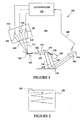
- the LPD 100 includes three lasers 102, 104, 106, each capable of emitting a beam of light 108, 110, 112 consisting of a unique color, such as red, green or blue.
- a unique color such as red, green or blue.
- the lasers 102, 104, 106 may be arranged in a common plane 114 with the beams of light 108, 110, 112 being angularly directed relative to one another to fall on a substantially common location 116 on a first scanning device, such as a first scanning mirror 118, from where they are reflected as beams of light 120, 122, 124.
- a first scanning device such as a first scanning mirror 118
- the lasers 102, 104, 106 need not be arranged in a common plane, but rather may be angularly disposed in at least two dimensions with respect to the axis of rotation of the first scanning mirror 118. Deviations from the plane 114 may be compensated for by controlling the timing of the lasers 102, 104, 106, as discussed below.
- the first scanning mirror 118 oscillates on an axis 120 at a relatively high rate (e.g., about 20-30 KHz). Rogation or oscillation of the first scanning mirror 118 causes the beams of light 108, 110, 112 to be moved. That is, as the angular position of the first scanning mirror 118 alters, so to does the angle of reflection of the beams of light 120, 122, 124 from the first scanning mirror 118. Thus, as the mirror oscillates the reflected beams of light 120, 122, 124 are scanned to produce movement of the beams of light 120, 122, 124 along one component of the two-dimensional display.
- a relatively high rate e.g., about 20-30 KHz
- the second component of the two-dimensional display is produced by a second scanning device, such as a mirror 126.
- the second mirror 126 is coupled to a motor 128 at a pivot point 130 so as to produce rotational or oscillating movement about an axis that is substantially orthogonal to the axis of rotation of the first mirror 118.
- the beams of light 120, 122, 124 are reflected off of the second mirror 126 as beams of light 132, 134, 136 and directed to a viewing surface 138.
- the viewing surface 138 may take on any of a variety of forms.
- the viewing surface 138 may be a fixed screen that may be front or back lit by the lasers 102, 104, 106 and may be contained in a housing (not shown) that is common with the LPD 100, or alternatively, the viewing surface 138 may take the form of any convenient, generally flat surface, such as a wall or screen, spaced from the LPD 100.
- the second mirror 126 oscillates or rotates at a relatively slow rate, as compared to the rate of the first mirror 118 (e.g., about 60hz).
- the beams of light 132, 134, 136 generally follow a path 140 on the display surface 138.
- the path 140 is similar in shape and concept to a raster scan commonly employed in cathode ray tube televisions an computer monitors.
- first and second scanning mirrors 118, 126 While the instant invention is described herein in the context of an embodiment that employs separate first and second scanning mirrors 118, 126, those skilled in the art will appreciate that a similar path 140 may be produced by using a single mirror.
- the single mirror would be capable of being moved about two axis of rotation to provide the fast and slow oscillating movements along two orthogonal axes.
- a controller 142 is provided to controllably energize the lasers 102, 104, 106 to effectively cause the beams of light 120, 122, 124 to be collinear, such that they may be reflected off of the second mirror 126 and delivered to the same point on the viewing surface 138 relatively independent of the distance of the viewing surface 138 from the second mirror 126.
- the beams of light 120, 122 can be made to follow a single, common path (i.e., the beams of light 120, 122 are collinear). For example, if the laser 102 is energized at a first time t1, then the mirror 118 will be at a first position, as represented by the solid lines, and the beam of light 108 will reflect off of the mirror 118 as the beam of light 120.
- the mirror 118 will be at a second position, as represented by the dashed lines, and the beam of light 110 will reflect off of the mirror 118 as the beam of light 122.
- the time t2 By precisely controlling the time t2; the mirror 118 will be in a position to accurately reflect the beam of light 122 along substantially the same path as the beam of light 120.
- the beams of light 120, 122 are substantially collinear, but are slightly displaced in time. That is, the beams of light 120, 122 will now both be projected onto substantially the same point on the display surface 138, but at slightly different times. However, owing to the persistence of the human eye, the variation in timing is not detectable. That is, in the case of the three laser system described in Figure 1 , each of the lasers 102, 104, 106 will controllably deliver laser light of a unique color and intensity to substantially the same point on the viewing surface 132 within a relatively short window of time.
- the human eye will not detect the three separate colors, bur rather will perceive a blending of the three light beams such that a consistent and desired hue appears at that point on the viewing surface. Those skilled in the art will appreciate that this process may be repeated numerous times along the path 140 to recreate a picture on the viewing surface 132.
- a similar concept may be used to compensate for deviations arising in an alternative arrangement in which the lasers 102, 104, 106 are not located in the same plane 114.
- the laser light produced by each of the lasers that ultimately reaches the viewing surface may be displaced vertically relative to one another.
- the controller 142 may compensate for this vertical displacement by energizing the offset laser on a prior or subsequent horizontal scan across the viewing surface, depending upon whether the vertical displacement is upward or downward. For example, assume that a second beam of light is displaced vertically above a first beam of light. Thus, on a first horizontal scan across the viewing surface, the laser associated with the second beam of light is energized. On a subsequent horizontal scan across the viewing surface, which is vertically lower than the previous horizontal scan, the laser associated with the first beam of light is energized so that both beams of light arrive at the same vertical location on the viewing screen, but slightly displaced in time.
- a photodetector 144 is arranged to receive laser light reflected from the viewing surface 138.
- the photodetector 144 may take any of a variety of forms, including a single photosensitive element or a plurality of photosensitive elements arranged in a grid. In some embodiments, it may be useful to include a mechanical/optical system 146 to focus the reflected laser light onto the photodetector 144.
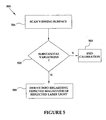
- the photodetector 144 is coupled to the controller 142 via a line 148. Signals indicative of the magnitude of the reflected laser light detected by the photodetector 144 may be communicated to the controller 142 over the line 148. In some instances, such as when the photodetector 144 is composed of a grid or an array of photosensitive elements, it may be useful to also convey information regarding the location of the reflected laser light. As discussed in more detail in conjunction with Figure 4 , the controller 142 may use the information regarding the magnitude of the reflected laser light to generally determine if conditions within the transmission path of the lasers have changed, such as by being interrupted by a person or object, or the viewing surface being altered. If such an event is detected, the operation of the lasers may be modified by, for example, substantially reducing the power delivered therefrom or by shutting them off.
- the routine begins at block 401 with the controller 142 using signals received from the photodetector 144 to determine the actual magnitude of the reflected laser light.
- the controller determines the anticipated magnitude of the reflected laser light. That is, the controller 142 "knows" the amount of power that it has requested the lasers to deliver to the viewing surface. Thus, based on an algorithm, look-up table, or the like, the controller may arrive at a magnitude of the reflected laser light that it expects to be received by the photodetector 144.
- the controller 142 can use the anticipated magnitude to determine if a variation has occurred within the optical transmission path of the lasers.
- the controller 142 may be instructed to control the power of the lasers (at block 404), such as by reducing the amount of power delivered therefrom. If the laser light is interrupted by a person or object, the amount of laser light reflected back to the photodetector 144 may vary substantially. In some instances, the actual laser light reflected back to the photodetector 144 may be substantially reduced; however, in other circumstances, the actual laser light reflected back to the photodetector 144 may be substantially increased. In either case, the controller 142 may elect to reduce power from the lasers, or in some instances to shut them off.
- the controller 142 may elect to reduce or even eliminate power for all three lasers over the entire viewing surface.
- the controller 142 may be programmed to reduce or eliminate power in only those regions where a variation in reflectivity is detected.
- the controller 142 may be programmed to reduce or eliminate power in those regions where a variation in reflectivity is detected plus an additional buffer area surrounding those area where the variation in reflectivity is detected.
- the error message may include information on how to reset or restore normal operation to the LPD. For example, a message such as, "Please aim your display at a uniform background for proper operation,” may be displayed.
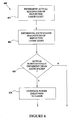
- a calibration process 500 that may be performed by the controller 142 is set forth in the flow chart of Figure 5 .
- the calibration process begins at block 501, with the controller 142 turning the lasers on for a short period of time, such as a period of time sufficient to scan at least a substantial portion of the viewing surface 138 at least one time. This first calibration scan may be accomplished with the lasers operating at relatively low power.
- the controller 142 receives feedback signals from the photodetector 144, indicating at least two types of useful information.
- the controller 142 can determine if the LPD is directed to a relatively uniform viewing surface by monitoring the signals delivered by the photodetector 144 for any substantial variations (at block 502). If substantial variations are detected, the controller 142 may discontinue the calibration process (at block 503) and display a message, such as, "Please aim your display at a uniform background for proper operation.”
- the controller 142 may derive information regarding the expected magnitude of the reflected laser light at other power levels based on the detected magnitude of the reflected laser light in the first calibration pass. For example, the controller may derive a formula that correlates the magnitude of the transmitted power level with the magnitude of the reflected laser light. The relationship may vary from a simple mathematical approximation based on an average ratio of the total laser light to a more complex algorithm that attempts to account for variations in reflectivity for each color of laser light. Alternatively, a more empirical approach may be had by performing additional scans at varying power levels.
- controller 142 may later access to estimate the expected magnitude of the reflected laser light.
- the controller 142 may access the table that most closely matches the current operating conditions of the lasers, or the controller 142 may include algorithms for interpolating between the tables.
- terms such as “processing” or “computing” or “calculating” or “determining” or “displaying” or the like refer to the action and processes of a computer system, or similar electronic computing device, that manipulates and transforms data represented as physical, electronic quantities within the computer system's registers and memories into other data similarly represented as physical quantities within the computer system's memories or registers or other such information storage, transmission or display devices.
- control units may include a microprocessor, a microcontroller, a digital signal processor, a processor card (including one or more microprocessors or controllers), or other control or computing devices.
- the storage devices referred to in this discussion may include one or more machine-readable storage media for storing data and instructions.
- the storage media may include different forms of memory including semiconductor memory devices such as dynamic or static random access memories (DRAMs or SRAMs), erasable and programmable read-only memories (EPROMs), electrically erasable and programmable read-only memories (EEPROMs) and flash memories; magnetic disks such as fixed, floppy, removable disks; other magnetic media including tape; and optical media such as compact disks (CDs) or digital video disks (DVDs).
- DRAMs or SRAMs dynamic or static random access memories
- EPROMs erasable and programmable read-only memories
- EEPROMs electrically erasable and programmable read-only memories
- flash memories such as fixed, floppy, removable disks
- CDs compact disks
- DVDs digital video disks
Landscapes
- Physics & Mathematics (AREA)
- Optics & Photonics (AREA)
- Engineering & Computer Science (AREA)
- Multimedia (AREA)
- Signal Processing (AREA)
- Mechanical Optical Scanning Systems (AREA)
- Lasers (AREA)
- Laser Surgery Devices (AREA)
- Transforming Electric Information Into Light Information (AREA)
- Semiconductor Lasers (AREA)
Applications Claiming Priority (3)
| Application Number | Priority Date | Filing Date | Title |
|---|---|---|---|
| US53400803P | 2003-12-31 | 2003-12-31 | |
| US10/836,813 US7030353B2 (en) | 2003-12-31 | 2004-04-30 | Method and apparatus for controllably reducing power delivered by a laser projection display |
| PCT/US2004/042835 WO2005067309A1 (en) | 2003-12-31 | 2004-12-21 | Method and apparatus for controllably reducing power delivered by a laser projection display |
Publications (2)
| Publication Number | Publication Date |
|---|---|
| EP1700485A1 EP1700485A1 (en) | 2006-09-13 |
| EP1700485B1 true EP1700485B1 (en) | 2010-09-01 |
Family
ID=34753015
Family Applications (1)
| Application Number | Title | Priority Date | Filing Date |
|---|---|---|---|
| EP04814964A Ceased EP1700485B1 (en) | 2003-12-31 | 2004-12-21 | Method and apparatus for controllably reducing power delivered by a laser projection display |
Country Status (6)
| Country | Link |
|---|---|
| US (1) | US7030353B2 (enExample) |
| EP (1) | EP1700485B1 (enExample) |
| JP (1) | JP2007517469A (enExample) |
| CN (1) | CN1902945B (enExample) |
| DE (1) | DE602004028961D1 (enExample) |
| WO (1) | WO2005067309A1 (enExample) |
Families Citing this family (36)
| Publication number | Priority date | Publication date | Assignee | Title |
|---|---|---|---|---|
| US7425073B2 (en) * | 2003-12-31 | 2008-09-16 | Symbol Technologies, Inc. | Method and apparatus for conserving power in a laser projection display |
| US8478386B2 (en) | 2006-01-10 | 2013-07-02 | Accuvein Inc. | Practitioner-mounted micro vein enhancer |
| US12295744B2 (en) | 2006-01-10 | 2025-05-13 | Accuvein, Inc. | Micro vein enhancer with two lasers and two optical detectors configured for removing surface topology |
| US9492117B2 (en) | 2006-01-10 | 2016-11-15 | Accuvein, Inc. | Practitioner-mounted micro vein enhancer |
| US8255040B2 (en) | 2006-06-29 | 2012-08-28 | Accuvein, Llc | Micro vein enhancer |
| US12089951B2 (en) | 2006-01-10 | 2024-09-17 | AccuVeiw, Inc. | Scanned laser vein contrast enhancer with scanning correlated to target distance |
| US10813588B2 (en) | 2006-01-10 | 2020-10-27 | Accuvein, Inc. | Micro vein enhancer |
| US8489178B2 (en) | 2006-06-29 | 2013-07-16 | Accuvein Inc. | Enhanced laser vein contrast enhancer with projection of analyzed vein data |
| US11253198B2 (en) | 2006-01-10 | 2022-02-22 | Accuvein, Inc. | Stand-mounted scanned laser vein contrast enhancer |
| US10238294B2 (en) | 2006-06-29 | 2019-03-26 | Accuvein, Inc. | Scanned laser vein contrast enhancer using one laser |
| US8838210B2 (en) | 2006-06-29 | 2014-09-16 | AccuView, Inc. | Scanned laser vein contrast enhancer using a single laser |
| US12408865B2 (en) | 2006-01-10 | 2025-09-09 | Accuvein Inc. | Vein imaging device with differential image resolution at the center and the extremities of the vein image |
| US9854977B2 (en) | 2006-01-10 | 2018-01-02 | Accuvein, Inc. | Scanned laser vein contrast enhancer using a single laser, and modulation circuitry |
| US11278240B2 (en) | 2006-01-10 | 2022-03-22 | Accuvein, Inc. | Trigger-actuated laser vein contrast enhancer |
| US12471844B2 (en) | 2006-06-29 | 2025-11-18 | Accuvein, Inc. | Scanned laser vein contrast enhancer with full stopping of scanner movement during scan line reversals |
| US8244333B2 (en) | 2006-06-29 | 2012-08-14 | Accuvein, Llc | Scanned laser vein contrast enhancer |
| US8463364B2 (en) | 2009-07-22 | 2013-06-11 | Accuvein Inc. | Vein scanner |
| US8730321B2 (en) | 2007-06-28 | 2014-05-20 | Accuvein, Inc. | Automatic alignment of a contrast enhancement system |
| US8594770B2 (en) * | 2006-06-29 | 2013-11-26 | Accuvein, Inc. | Multispectral detection and presentation of an object's characteristics |
| US8665507B2 (en) * | 2006-06-29 | 2014-03-04 | Accuvein, Inc. | Module mounting mirror endoscopy |
| KR20080060923A (ko) * | 2006-12-27 | 2008-07-02 | 삼성전자주식회사 | 복수개의 레이저 광원에 공급되는 전원을 제어하기 위한레이저 프로젝터 및 그 방법 |
| DE102007042720A1 (de) * | 2007-09-07 | 2009-03-12 | Robert Bosch Gmbh | Laserprojektionssystem mit Leistungsüberprüfung |
| JP5157381B2 (ja) * | 2007-11-14 | 2013-03-06 | 船井電機株式会社 | 画像表示装置 |
| US7997742B2 (en) * | 2008-03-25 | 2011-08-16 | Microvision, Inc. | Capacitive comb feedback for high speed scan mirror |
| US20090251670A1 (en) * | 2008-04-03 | 2009-10-08 | Motorola, Inc. | Optical feedback for high speed scan mirror |
| US8290208B2 (en) * | 2009-01-12 | 2012-10-16 | Eastman Kodak Company | Enhanced safety during laser projection |
| US9061109B2 (en) | 2009-07-22 | 2015-06-23 | Accuvein, Inc. | Vein scanner with user interface |
| CN102375309A (zh) * | 2010-08-26 | 2012-03-14 | 鸿富锦精密工业(深圳)有限公司 | 投影机光线调整系统及方法 |
| US8690342B2 (en) * | 2010-08-31 | 2014-04-08 | Corning Incorporated | Energy transfer in scanning laser projectors |
| CN101976011B (zh) * | 2010-09-03 | 2012-05-16 | 朱强 | Md短焦距投影显示装置 |
| DE102010063921A1 (de) * | 2010-12-22 | 2012-06-28 | Osram Ag | Projektionsvorrichtung zum Projizieren mindestens eines Bildes auf eine Projektionsfläche und entsprechendes Verfahren zum Betreiben einer Projektionsvorrichtung |
| KR20120097727A (ko) * | 2011-02-25 | 2012-09-05 | 엘지전자 주식회사 | 레이저 프로젝터 및 그의 신호 처리방법 |
| JP2013061598A (ja) * | 2011-09-15 | 2013-04-04 | Funai Electric Co Ltd | プロジェクタおよびプロジェクタ機能を有する電子機器 |
| US9072426B2 (en) | 2012-08-02 | 2015-07-07 | AccuVein, Inc | Device for detecting and illuminating vasculature using an FPGA |
| US10376148B2 (en) | 2012-12-05 | 2019-08-13 | Accuvein, Inc. | System and method for laser imaging and ablation of cancer cells using fluorescence |
| US9140971B2 (en) * | 2013-10-31 | 2015-09-22 | Microvision, Inc. | Scanning laser proximity detection |
Family Cites Families (20)
| Publication number | Priority date | Publication date | Assignee | Title |
|---|---|---|---|---|
| US5029975A (en) * | 1990-01-24 | 1991-07-09 | The Mitre Corporation | Despeckling screen utilizing optical fibers and method of reducing interference using same |
| EP0884914A1 (en) * | 1993-02-03 | 1998-12-16 | Nitor | Methods and apparatus for image projection |
| US5311321A (en) * | 1993-04-22 | 1994-05-10 | Corporation For Laser Optics Research | Laser video imaging system with pulse backtrack and method |
| DE19640404A1 (de) * | 1996-09-30 | 1998-04-09 | Ldt Gmbh & Co | Vorrichtung zur Darstellung von Bildern |
| CA2273040C (en) * | 1996-11-29 | 2004-09-21 | Corporation For Laser Optics Research | Monochromatic r,g,b laser light source display system and method |
| CA2321778C (en) * | 1998-03-06 | 2004-06-29 | Matsushita Electric Industrial Co., Ltd. | Lcd projector |
| JP2000019637A (ja) * | 1998-07-03 | 2000-01-21 | Seiko Epson Corp | 投写型表示装置 |
| US6937221B2 (en) * | 1998-08-05 | 2005-08-30 | Microvision, Inc. | Scanned beam display |
| US6140979A (en) * | 1998-08-05 | 2000-10-31 | Microvision, Inc. | Scanned display with pinch, timing, and distortion correction |
| JP3447608B2 (ja) * | 1999-03-26 | 2003-09-16 | 株式会社クボタ | 作業機械の制御装置 |
| US6018408A (en) * | 1999-03-26 | 2000-01-25 | Samsung Electronics Co., Ltd. | Laser projection display apparatus |
| US6515781B2 (en) * | 1999-08-05 | 2003-02-04 | Microvision, Inc. | Scanned imaging apparatus with switched feeds |
| JP4192400B2 (ja) | 1999-12-28 | 2008-12-10 | ソニー株式会社 | 画像投射方法及び画像投射装置 |
| US6224216B1 (en) * | 2000-02-18 | 2001-05-01 | Infocus Corporation | System and method employing LED light sources for a projection display |
| JP2002006397A (ja) | 2000-06-22 | 2002-01-09 | Sony Corp | 画像表示装置 |
| US6489934B1 (en) * | 2000-07-07 | 2002-12-03 | Judah Klausner | Cellular phone with built in optical projector for display of data |
| KR20040028919A (ko) | 2001-07-06 | 2004-04-03 | 익스플레이 엘티디. | 영상 투사 장치 및 방법 |
| JP2003021800A (ja) * | 2001-07-10 | 2003-01-24 | Canon Inc | 投射型表示装置 |
| JP4366631B2 (ja) | 2002-06-10 | 2009-11-18 | ソニー株式会社 | 画像投射装置及び画像投射方法 |
| AU2003208566A1 (en) | 2003-01-08 | 2004-08-10 | Explay Ltd. | An image projecting device and method |
-
2004
- 2004-04-30 US US10/836,813 patent/US7030353B2/en not_active Expired - Lifetime
- 2004-12-21 WO PCT/US2004/042835 patent/WO2005067309A1/en not_active Ceased
- 2004-12-21 DE DE602004028961T patent/DE602004028961D1/de not_active Expired - Lifetime
- 2004-12-21 JP JP2006547240A patent/JP2007517469A/ja active Pending
- 2004-12-21 EP EP04814964A patent/EP1700485B1/en not_active Ceased
- 2004-12-21 CN CN2004800393414A patent/CN1902945B/zh not_active Expired - Fee Related
Also Published As
| Publication number | Publication date |
|---|---|
| CN1902945B (zh) | 2010-08-04 |
| EP1700485A1 (en) | 2006-09-13 |
| CN1902945A (zh) | 2007-01-24 |
| US20050175048A1 (en) | 2005-08-11 |
| WO2005067309A1 (en) | 2005-07-21 |
| US7030353B2 (en) | 2006-04-18 |
| JP2007517469A (ja) | 2007-06-28 |
| DE602004028961D1 (de) | 2010-10-14 |
Similar Documents
| Publication | Publication Date | Title |
|---|---|---|
| EP1700485B1 (en) | Method and apparatus for controllably reducing power delivered by a laser projection display | |
| US7425073B2 (en) | Method and apparatus for conserving power in a laser projection display | |
| US7445339B2 (en) | Color laser projection display | |
| US7508496B2 (en) | Method for driving a laser scanner | |
| US7304619B2 (en) | Method and apparatus for controllably compensating for distortions in a laser projection display | |
| CN101268402B (zh) | 图像投射装置 | |
| US20050035943A1 (en) | Projection type image display apparatus | |
| US7679579B2 (en) | Projection type image display apparatus | |
| US10088742B2 (en) | Laser projection display system configured to execute scanning with laser light in accordance with image signals | |
| EP1690419A1 (en) | Laser projector having silhouette blanking | |
| CN104698727A (zh) | 用于激光投影设备的人体保护方法、装置和激光投影设备 | |
| US12003898B2 (en) | Projector and projection method | |
| US7273281B2 (en) | Method and apparatus for aligning a plurality of lasers in an electronic display device | |
| US7163294B2 (en) | Method and apparatus for providing an interface between a liquid crystal display controller and a laser projection display | |
| US7274718B2 (en) | Electronic alignment of acousto-optic modulator for modulating a laser | |
| JP2007324643A (ja) | 画像投射装置及び画像投射スクリーン及び画像表示システム | |
| CN100385959C (zh) | 用于在图像投影期间节省电功率消耗的装置 | |
| JP2004012760A (ja) | 複数ビーム走査装置 | |
| CN1906950A (zh) | 用于可控制地补偿激光投影显示器中的失真的方法和设备 | |
| US20210041983A1 (en) | Projection system, position detection system, and method for controlling position detection system | |
| JP2009244632A (ja) | 投射型表示装置及びその制御方法 |
Legal Events
| Date | Code | Title | Description |
|---|---|---|---|
| PUAI | Public reference made under article 153(3) epc to a published international application that has entered the european phase |
Free format text: ORIGINAL CODE: 0009012 |
|
| 17P | Request for examination filed |
Effective date: 20060523 |
|
| AK | Designated contracting states |
Kind code of ref document: A1 Designated state(s): DE FR GB |
|
| DAX | Request for extension of the european patent (deleted) | ||
| RBV | Designated contracting states (corrected) |
Designated state(s): DE FR GB |
|
| 17Q | First examination report despatched |
Effective date: 20080507 |
|
| GRAP | Despatch of communication of intention to grant a patent |
Free format text: ORIGINAL CODE: EPIDOSNIGR1 |
|
| GRAS | Grant fee paid |
Free format text: ORIGINAL CODE: EPIDOSNIGR3 |
|
| GRAA | (expected) grant |
Free format text: ORIGINAL CODE: 0009210 |
|
| AK | Designated contracting states |
Kind code of ref document: B1 Designated state(s): DE FR GB |
|
| REG | Reference to a national code |
Ref country code: GB Ref legal event code: FG4D |
|
| REF | Corresponds to: |
Ref document number: 602004028961 Country of ref document: DE Date of ref document: 20101014 Kind code of ref document: P |
|
| REG | Reference to a national code |
Ref country code: GB Ref legal event code: 732E Free format text: REGISTERED BETWEEN 20101202 AND 20101208 |
|
| REG | Reference to a national code |
Ref country code: FR Ref legal event code: TP |
|
| REG | Reference to a national code |
Ref country code: DE Ref legal event code: R081 Ref document number: 602004028961 Country of ref document: DE Owner name: MICROVISION, INC. ( N. D. GES. D. STAATES DELA, US Free format text: FORMER OWNER: SYMBOL TECHNOLOGIES, INC., HOLTSVILLE, US Effective date: 20110330 Ref country code: DE Ref legal event code: R081 Ref document number: 602004028961 Country of ref document: DE Owner name: MICROVISION, INC. ( N. D. GES. D. STAATES DELA, US Free format text: FORMER OWNER: SYMBOL TECHNOLOGIES, INC., HOLTSVILLE, N.Y., US Effective date: 20110330 |
|
| PLBE | No opposition filed within time limit |
Free format text: ORIGINAL CODE: 0009261 |
|
| STAA | Information on the status of an ep patent application or granted ep patent |
Free format text: STATUS: NO OPPOSITION FILED WITHIN TIME LIMIT |
|
| 26N | No opposition filed |
Effective date: 20110606 |
|
| REG | Reference to a national code |
Ref country code: DE Ref legal event code: R097 Ref document number: 602004028961 Country of ref document: DE Effective date: 20110606 |
|
| REG | Reference to a national code |
Ref country code: FR Ref legal event code: PLFP Year of fee payment: 12 |
|
| REG | Reference to a national code |
Ref country code: FR Ref legal event code: PLFP Year of fee payment: 13 |
|
| REG | Reference to a national code |
Ref country code: FR Ref legal event code: PLFP Year of fee payment: 14 |
|
| PGFP | Annual fee paid to national office [announced via postgrant information from national office to epo] |
Ref country code: DE Payment date: 20181211 Year of fee payment: 15 |
|
| PGFP | Annual fee paid to national office [announced via postgrant information from national office to epo] |
Ref country code: FR Payment date: 20181120 Year of fee payment: 15 Ref country code: GB Payment date: 20181219 Year of fee payment: 15 |
|
| REG | Reference to a national code |
Ref country code: DE Ref legal event code: R119 Ref document number: 602004028961 Country of ref document: DE |
|
| GBPC | Gb: european patent ceased through non-payment of renewal fee |
Effective date: 20191221 |
|
| PG25 | Lapsed in a contracting state [announced via postgrant information from national office to epo] |
Ref country code: DE Free format text: LAPSE BECAUSE OF NON-PAYMENT OF DUE FEES Effective date: 20200701 Ref country code: GB Free format text: LAPSE BECAUSE OF NON-PAYMENT OF DUE FEES Effective date: 20191221 Ref country code: FR Free format text: LAPSE BECAUSE OF NON-PAYMENT OF DUE FEES Effective date: 20191231 |