EP1699670B1 - Servomoteur d'assistance au freinage alimente par un circuit de climatisation - Google Patents
Servomoteur d'assistance au freinage alimente par un circuit de climatisation Download PDFInfo
- Publication number
- EP1699670B1 EP1699670B1 EP04816408A EP04816408A EP1699670B1 EP 1699670 B1 EP1699670 B1 EP 1699670B1 EP 04816408 A EP04816408 A EP 04816408A EP 04816408 A EP04816408 A EP 04816408A EP 1699670 B1 EP1699670 B1 EP 1699670B1
- Authority
- EP
- European Patent Office
- Prior art keywords
- fluid
- conditioning circuit
- air conditioning
- source
- state
- Prior art date
- Legal status (The legal status is an assumption and is not a legal conclusion. Google has not performed a legal analysis and makes no representation as to the accuracy of the status listed.)
- Expired - Lifetime
Links
Images
Classifications
-
- B—PERFORMING OPERATIONS; TRANSPORTING
- B60—VEHICLES IN GENERAL
- B60T—VEHICLE BRAKE CONTROL SYSTEMS OR PARTS THEREOF; BRAKE CONTROL SYSTEMS OR PARTS THEREOF, IN GENERAL; ARRANGEMENT OF BRAKING ELEMENTS ON VEHICLES IN GENERAL; PORTABLE DEVICES FOR PREVENTING UNWANTED MOVEMENT OF VEHICLES; VEHICLE MODIFICATIONS TO FACILITATE COOLING OF BRAKES
- B60T13/00—Transmitting braking action from initiating means to ultimate brake actuator with power assistance or drive; Brake systems incorporating such transmitting means, e.g. air-pressure brake systems
- B60T13/10—Transmitting braking action from initiating means to ultimate brake actuator with power assistance or drive; Brake systems incorporating such transmitting means, e.g. air-pressure brake systems with fluid assistance, drive, or release
- B60T13/24—Transmitting braking action from initiating means to ultimate brake actuator with power assistance or drive; Brake systems incorporating such transmitting means, e.g. air-pressure brake systems with fluid assistance, drive, or release the fluid being gaseous
- B60T13/46—Vacuum systems
- B60T13/52—Vacuum systems indirect, i.e. vacuum booster units
-
- B—PERFORMING OPERATIONS; TRANSPORTING
- B60—VEHICLES IN GENERAL
- B60H—ARRANGEMENTS OF HEATING, COOLING, VENTILATING OR OTHER AIR-TREATING DEVICES SPECIALLY ADAPTED FOR PASSENGER OR GOODS SPACES OF VEHICLES
- B60H1/00—Heating, cooling or ventilating devices
- B60H1/32—Cooling devices
- B60H1/3204—Cooling devices using compression
Definitions
- the invention relates generally to braking techniques applied to motor vehicles.
- the invention relates to a braking device for a motor vehicle equipped with an air conditioning circuit containing a refrigerant, a compressor and an expander, this device itself including a first fluid source selectively delivering a gaseous fluid to relatively high pressure, a second fluid source selectively delivering the gaseous fluid at a relatively low pressure, and a pneumatic brake booster comprising a variable volume working chamber and a control valve selectively actuated by a first or a second bias for respectively connecting the working chamber to the first or second fluid source.
- a braking actuator including a fluid source that includes a first portion of an air conditioning circuit, disposed downstream of a compressor and upstream of a pressure reducer, in a refrigerant circulation direction in an air conditioning circuit.
- the invention which fits into this context, aims to push the limits of this delicate compromise.
- the device of the invention which moreover conforms to the generic definition given in the preamble above, is essentially characterized by the characterizing part of claim 1.
- the second fluid source comprises a second portion of the air conditioning circuit, disposed downstream of the expander and upstream of the compressor in the direction of circulation of the refrigerant.
- the first portion of the air conditioning circuit may comprise a high pressure accumulator
- the second portion of the air conditioning circuit may in turn comprise a low pressure accumulator
- the servomotor may also have an active valve, of the type described for example in the patents US-5,172,964 , FR-2,724,356 , or EP-A-0 171 585 , and can be controlled by a signal, generally of an electrical nature, to cause actuation of the servomotor.
- the valve is therefore sensitive to an actuation signal selectively having at least a first state or a second state, and the first and second states of this actuation signal respectively constitute the first and second solicitations for the valve.
- this device may also comprise a control signal generator adapted to selectively produce a control signal. , and a signal combining circuit, said signal combining circuit supplying the valve with the actuation signal in its first state in response to the simultaneous detection of the control signal and the passive state of the brake motors.
- Such an arrangement thus makes it possible to provide the device of the invention with an auxiliary energy parking brake function, for example electrical.
- the invention relates to a braking device for a motor vehicle equipped with an air conditioning circuit K.
- such an air conditioning circuit comprises a pipe in which circulates a gaseous refrigerant at ambient temperature and pressure, a compressor K1, a pressure regulator K2, a system K3 for condensation and extraction of calories, a system K4 evaporation and extraction of frigories, a pressure switch K5 and a reserve bottle of fluid K6.
- the refrigerant circulates, in a direction of circulation X and in a decreasing overall evolution of its pressure and temperature, from a first portion KC1 of the air conditioning circuit K disposed downstream of the compressor K1 and upstream of the expander K2, into a second portion KC2 of the air conditioning circuit, disposed downstream of the expander K2 and upstream of the compressor K1.
- the braking device includes, in known manner, two fluid sources F1 and F2 delivering at will a gaseous fluid at respectively relatively high and relatively low pressures, and a pneumatic servo brake assist F3.
- the servomotor comprises at least one working chamber F30 of variable volume and a control valve F31 whose role is to connect the working chamber F30 to the source of high pressure fluid F1 or to the source of low pressure fluid F2 in response respectively at a first or a second bias it receives, for example in the form of antagonistic forces of actuation and return acting on a brake pedal F33 and / or in the form of electrical control signals.
- the source of high pressure fluid F1 comprises the portion KC1 of the air conditioning circuit K which, in the direction of circulation X of the refrigerant inside the air conditioning circuit K, is arranged downstream.
- compressor K1 and upstream of the expander K2 which advantageously includes itself a high pressure accumulator KS1.
- the source of low pressure fluid F2 preferably comprises the portion KC2 of the air conditioning circuit which, in the direction of circulation X of the refrigerant fluid, is disposed downstream of the expander K2 and upstream of the compressor K1, and which advantageously includes itself a low pressure accumulator KS2.
- a single-chamber servomotor which is closed by a movable wall subjected on one of its faces to atmospheric pressure and on its other face to the pressure prevailing in the chamber.
- the valve connects the single chamber to the source of high pressure fluid F1 or the source of low pressure fluid F2 depending on the desired intensity of braking.
- valve F31 of the servomotor F3 adopts for example a first state, in which it connects the working chamber F30 to the high-pressure source F1, in response to the receipt of an actuation signal Sact placed in a first state Sact1, while it adopts a second state, in which it connects the working chamber F30 to the low pressure source F2, in response to the receipt of the actuation signal Sact placed in a second state Sact2 .
- the brake motors F4 and F5 thus adopt at will an active state corresponding to a mechanical interlock of the parking brake associated with each engine, or a passive state corresponding to a parking brake release associated with each engine, and include, for example, respective sensors to emit respective signals E4 and E5, for example electrical, accounting for these different states.
- the device of the invention may further comprise a control signal generator Gcom and a signal combining circuit Clog.
- the Clog circuit itself comprises an AND gate Clogl and a logic gate NO (AND) Clog2.
- the AND logic gate Clog1 receives the state signals E4 and E5 and produces an intermediate signal Slogl.
- the logic gate NO (AND) Clog2 which receives the intermediate signal Slog1 and a control signal Scom emitted by the control signal generator Gcom, produces, at the output of the circuit Clog and destined for the valve F31 of the servomotor F3, the signal actuator Sact in its first state Sact1 in response to the simultaneous detection of the control signal Scom and the passive state E4p and E5p of the brake motors F4 and F5.
- the driver of this vehicle triggers the Gcom generator, which immediately delivers a Scom control signal.
- the state signals E4 and E5 are at a low level, as is the intermediate signal Slogl.
- the NO (AND) gate Clog2 which receives the signal Scom at the high level and the signal Slog1 at the low level, delivers the actuation signal Sact in its first state Sact1.
- valve F31 On receipt of the actuating signal Sact in its first state Sact1, the valve F31 connects the working chamber F30 to the source F1 of high pressure, which causes the actuation of the servomotor F3 and that of the brake motors F4 and F5.
- the gate NO (ET) Clog2 stops delivering the actuation signal Sact in its first state Sact1, as soon as the two brake motors F4 and F5 have performed the parking brake lock.
- the Scom signal that it emits switches the gate Clog2 due to the high level of signal Slog1, the signal Sact thus placing itself in its second state Sact2, establishing the communication between the working chamber F30 and the low-pressure source F2, causing the servomotor F3 to return to its rest position.
Landscapes
- Engineering & Computer Science (AREA)
- Mechanical Engineering (AREA)
- Transportation (AREA)
- Physics & Mathematics (AREA)
- Thermal Sciences (AREA)
- Braking Systems And Boosters (AREA)
- Braking Arrangements (AREA)
- Fluid-Pressure Circuits (AREA)
- Valves And Accessory Devices For Braking Systems (AREA)
Description
- L'invention concerne, de façon générale, les techniques de freinage appliquées aux véhicules automobiles.
- Plus précisément, l'invention concerne un dispositif de freinage pour un véhicule automobile équipé d'un circuit de climatisation renfermant un fluide réfrigérant, un compresseur et un détendeur, ce dispositif incluant lui-même une première source de fluide délivrant sélectivement un fluide gazeux à pression relativement élevée, une seconde source de fluide délivrant sélectivement le fluide gazeux à pression relativement basse, et un servomoteur pneumatique d'assistance au freinage comprenant une chambre de travail de volume variable et un clapet de commande sélectivement actionné par une première ou une seconde sollicitations pour relier respectivement la chambre de travail à la première ou à la seconde source de fluide.
- Le document
EP-A-0171585 décrit un dispositif de freinage comme défini dans le préambule de la revendication 1. - Le document de Hyundai Motor Company avec le titre: "BRAKE BOOSTER WITH USING THE HIGH-PRESSURE REFRIGERANT OF AIR CONDITIONER", KOREAN PATENT ABSTRACTS, numéro de publication
00205871 B1, 6-Avril-1999 - L'industrie automobile évolue depuis plusieurs années à la poursuite de plusieurs ' objectifs majeurs, qui incluent notamment la recherche d'une sécurité optimale et celle d'un confort accru.
- Cet état de faits conduit à recourir, sur les véhicules automobiles actuels, à un nombre croissant d'organes nouveaux liés soit à la sécurité, soit au confort.
- Or cette évolution est ralentie par deux autres contraints auxquelles est soumise l'industrie automobile, à savoir l'allègement des véhicules et, corrélativement, la réduction de leur consommation énergétique.
- L'invention, qui s'inscrit dans ce contexte, a pour but de repousser les limites de ce délicat compromis.
- A cette fin, le dispositif de l'invention, par ailleurs conforme à la définition générique qu'en donne le préambule ci-dessus, est essentiellement caractérisé par la partie caractérisante de la revendication 1.
- De préférence, la seconde source de fluide comprend une seconde portion du circuit de climatisation, disposée en aval du détendeur et en amont du compresseur dans le sens de circulation du fluide réfrigérant.
- De manière avantageuse, la première portion du circuit de climatisation peut comprendre un accumulateur haute pression, la seconde portion du circuit de climatisation pouvant quant à elle comprendre un accumulateur basse pression.
- Le servomoteur peut en outre disposer d'un clapet actif, du type décrit par exemple dans les brevets
US-5 172 964 ,FR-2 724 356 EP-A-0 171 585 , et susceptible d'être commandé par un signal, en général de nature électrique, pour provoquer l'actionnement du servomoteur. - Dans ce cas, le clapet est donc sensible à un signal d'actionnement présentant sélectivement au moins un premier état ou un second état, et les premier et second états de ce signal d'actionnement constituent respectivement les première et seconde sollicitations pour le clapet.
- Dans le cas classique où le dispositif de freinage comprend au moins deux moteurs de frein mus par le servomoteur et adoptant sélectivement un état actif ou un état passif, ce dispositif peut aussi comprendre un générateur de signal de commande propre à produire sélectivement un signal de commande, et un circuit de combinaison de signaux, ce circuit de combinaison de signaux délivrant au clapet le signal d'actionnement dans son premier état en réponse à la détection simultanée du signal de commande et de l'état passif des moteurs de frein.
- Un tel agencement permet ainsi de doter le dispositif de l'invention d'une fonction de frein de parking à énergie auxiliaire, par exemple électrique.
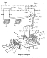
- D'autres caractéristiques et avantages de l'invention ressortiront clairement de la description qui en est faite ci-après, à titre indicatif et nullement limitatif, en référence au dessin unique annexé, qui représente de façon schématique un dispositif conforme à l'invention.
- Comme annoncé précédemment, l'invention concerne un dispositif de freinage pour un véhicule automobile équipé d'un circuit de climatisation K.
- De façon traditionnelle, un tel circuit de climatisation comprend une canalisation dans laquelle circule un fluide réfrigérant gazeux à la température et à la pression ambiantes, un compresseur K1, un détendeur K2, un système K3 de condensation et d'extraction de calories, un système K4 d'évaporation et d'extraction de frigories, un pressostat K5 et une bouteille de réserve de fluide K6.
- Dans la canalisation de ce circuit K, le fluide réfrigérant circule, suivant un sens de circulation X et suivant une évolution globalement décroissante de sa pression et de sa température, depuis une première portion KC1 du circuit de climatisation K, disposée en aval du compresseur K1 et en amont du détendeur K2, jusque dans une seconde portion KC2 du circuit de climatisation, disposée en aval du détendeur K2 et en amont du compresseur K1.
- Le dispositif de freinage inclut, de façon connue, deux sources de fluide F1 et F2 délivrant à volonté un fluide gazeux à des pressions respectivement relativement élevée et relativement basse, ainsi qu'un servomoteur pneumatique d'assistance au freinage F3.
- Le servomoteur comprend au moins une chambre de travail F30 de volume variable et un clapet de commande F31 dont le rôle est de relier la chambre de travail F30 à la source de fluide haute pression F1 ou à la source de fluide basse pression F2 en réponse respectivement à une première ou à une seconde sollicitations qu'il reçoit, par exemple sous la forme de forces antagonistes d'actionnement et de rappel agissant sur une pédale de frein F33 et / ou sous la forme de signaux électriques de commande.
- Selon un aspect essentiel de l'invention, la source de fluide haute pression F1 comprend la portion KC1 du circuit de climatisation K qui, dans le sens de circulation X du fluide réfrigérant à l'intérieur du circuit de climatisation K, est disposée en aval du compresseur K1 et en amont du détendeur K2, et qui inclut avantageusement elle-même un accumulateur haute pression KS1.
- Par ailleurs, la source de fluide basse pression F2 comprend de préférence la portion KC2 du circuit de climatisation qui, dans le sens de circulation X du fluide réfrigérant, est disposée en aval du détendeur K2 et en amont du compresseur K1, et qui inclut avantageusement elle-même un accumulateur basse pression KS2.
- En variante, on utilise un servomoteur à chambre unique fermée par une paroi mobile soumise sur l'une de ses faces à la pression atmosphérique et sur son autre face à la pression régnant dans la chambre. Le clapet relie la chambre unique à la source de fluide haute pression F1 ou à la source de fluide basse pression F2 en fonction de l'intensité souhaitée du freinage.
- Dans le cas préféré où le clapet F31 du servomoteur F3 est actif, il adopte par exemple un premier état, dans lequel il relie la chambre de travail F30 à la source haute pression F1, en réponse à la réception d'un signal d'actionnement Sact placé dans un premier état Sact1, tandis qu'il adopte un second état, dans lequel il relie la chambre de travail F30 à la source basse pression F2, en réponse à la réception du signal d'actionnement Sact placé dans un second état Sact2.
- Dans le cas le plus traditionnel, un dispositif de freinage utilisable dans le cadre de l'invention comprend deux moteurs hydrauliques de frein arrière, F4 et F5, qui sont mus par le servomoteur F3 agissant sur ces moteurs par l'intermédiaire d'un maître-cylindre hydraulique F32.
- Les moteurs de frein F4 et F5 adoptent ainsi à volonté un état actif correspondant à un verrouillage mécanique du frein de parking associé à chaque moteur, ou un état passif correspondant à un déverrouillage de frein de parking associé à chaque moteur, et incluent par exemple des capteurs respectifs propres à émettre des signaux respectifs E4 et E5, par exemple électriques, rendant compte de ces différents états.
- Dans un mode de réalisation avantageux, le dispositif de l'invention peut en outre comprendre un générateur Gcom de signal de commande et un circuit Clog de combinaison de signaux.
- Le circuit Clog comprend lui-même une porte logique ET Clogl et une porte logique NON(ET) Clog2.
- La porte logique ET Clog1 reçoit les signaux d'état E4 et E5 et produit un signal intermédiaire Slogl.
- La porte logique NON(ET) Clog2, qui reçoit le signal intermédiaire Slog1 et un signal de commande Scom émis par le générateur Gcom de signal de commande, produit, en sortie du circuit Clog et à destination du clapet F31 du servomoteur F3, le signal d'actionnement Sact dans son premier état Sact1 en réponse à la détection simultanée du signal de commande Scom et de l'état passif E4p et E5p des moteurs de frein F4 et F5.
- Le fonctionnement du dispositif tel que décrit jusqu'à présent est le suivant.
- Lorsqu'il souhaite immobiliser le véhicule en stationnement prolongé, le conducteur de ce véhicule déclenche le générateur Gcom, qui délivre aussitôt un signal de commande Scom.
- Les moteurs de frein F4 et F5 étant alors supposés au repos, les signaux d'état E4 et E5 sont à un niveau bas, de même que le signal intermédiaire Slogl.
- La porte NON(ET) Clog2, qui reçoit le signal Scom au niveau haut et le signal Slog1 au niveau bas, délivre le signal d'actionnement Sact dans son premier état Sact1.
- A réception du signal d'actionnement Sact dans son premier état Sact1, le clapet F31 relie la chambre de travail F30 à la source F1 de haute pression, ce qui provoque l'actionnement du servomoteur F3 et celui des moteurs de freins F4 et F5.
- Lorsque les moteurs de freins F4 et F5 ont atteint leur état actif, correspondant par exemple au verrouillage mécanique de frein de parking, le signal intermédiaire Slog1 passe au niveau haut. '
- Comme entre-temps le générateur Gcom a cessé de produire le signal de commande Scom, la porte NON(ET) Clog2 arrête de délivrer le signal d'actionnement Sact dans son premier état Sact1, dès que les deux moteurs de frein F4 et F5 ont effectué le verrouillage de frein de parking.
- Cependant, dès que le générateur Gcom est une nouvelle fois actionné par le conducteur, le signal Scom qu'il émet fait basculer la porte Clog2 en raison du niveau haut du signal Slog1, le signal Sact se plaçant ainsi dans son second état Sact2, établissant la communication entre la chambre de travail F30 et la source de basse pression F2, et provoquant le retour du servomoteur F3 dans sa position de repos.
Claims (5)
- Dispositif de freinage pour un véhicule automobile équipé d'un circuit de climatisation (K) renfermant un fluide réfrigérant, un compresseur (K1) et un détendeur (K2), ce dispositif incluant lui-même une première source de fluide (F1) délivrant sélectivement un fluide gazeux à pression relativement élevée, une seconde source de fluide (F2) délivrant sélectivement le fluide gazeux à pression relativement basse, et un servomoteur pneumatique d'assistance au freinage (F3) comprenant une chambre de travail (F30) de volume variable et un clapet de commande (F31) sélectivement actionné par une première ou une seconde sollicitations pour relier respectivement la chambre de travail (F30) à la première (F1) ou à la seconde (F2) source de fluide, caractérisé en ce que la première source de fluide (F1) comprend une première portion (KC1) du circuit de climatisation (K), disposée en aval du compresseur (K1) et en amont du détendeur (K2), dans un sens de circulation (X) du fluide réfrigérant dans le circuit de climatisation (K) et en ce que la seconde source de fluide (F2) comprend une seconde portion (KC2) du circuit de climatisation, disposée en aval du détendeur (K2) et en amont du compresseur (K1) dans le sens de circulation (X) du fluide réfrigérant.
- Dispositif de freinage suivant la revendication précédente, caractérisé en ce que la première portion (KC1) du circuit de climatisation comprend un accumulateur haute pression (KS1).
- Dispositif de freinage suivant l'une quelconque des revendications précédentes, caractérisé en ce que la seconde portion (KC2) du circuit de climatisation comprend un accumulateur basse pression (KS2).
- Dispositif de freinage suivant l'une quelconque des revendications précédentes, caractérisé en ce que le clapet (F31) est sensible à un signal d'actionnement (Sact) présentant sélectivement au moins un premier état (Sact1) ou un second état (Sact2), et en ce que les premier et second états (Sact1, Sact2) du signal d'actionnement (Sact) constituent respectivement les première et seconde sollicitations pour le clapet (F31).
- Dispositif de freinage suivant la revendication 4, caractérisé en ce qu'il comprend au moins deux moteurs de frein (F4, F5) mus par le servomoteur (F3) et adoptant sélectivement un état mécaniquement verrouillé du frein de parking ou un état passif sans verrouillage mécanique du frein de parking, un générateur (Gcom) de signal de commande propre à produire sélectivement un signal de commande (Scom), et un circuit (Clog) de combinaison de signaux, ce circuit de combinaison de signaux délivrant au clapet (F31) le signal d'actionnement (Sact) dans son premier état (Sact1) en réponse à la détection simultanée du signal de commande (Scom) et de l'état sans verrouillage mécanique du frein de parking des moteurs de frein (F4, F5).
Applications Claiming Priority (2)
| Application Number | Priority Date | Filing Date | Title |
|---|---|---|---|
| FR0315494A FR2864497B1 (fr) | 2003-12-24 | 2003-12-24 | Dispositif de freinage utilisant un servomoteur d'assistance au freinage alimente par un circuit de climatisation |
| PCT/FR2004/003272 WO2005070740A2 (fr) | 2003-12-24 | 2004-12-13 | Servomoteur d'assistance au freinage alimente par un circuit de climatisation |
Publications (2)
| Publication Number | Publication Date |
|---|---|
| EP1699670A2 EP1699670A2 (fr) | 2006-09-13 |
| EP1699670B1 true EP1699670B1 (fr) | 2008-08-20 |
Family
ID=34639657
Family Applications (1)
| Application Number | Title | Priority Date | Filing Date |
|---|---|---|---|
| EP04816408A Expired - Lifetime EP1699670B1 (fr) | 2003-12-24 | 2004-12-13 | Servomoteur d'assistance au freinage alimente par un circuit de climatisation |
Country Status (7)
| Country | Link |
|---|---|
| US (1) | US7959237B2 (fr) |
| EP (1) | EP1699670B1 (fr) |
| JP (1) | JP2007516900A (fr) |
| AT (1) | ATE405461T1 (fr) |
| DE (1) | DE602004016046D1 (fr) |
| FR (1) | FR2864497B1 (fr) |
| WO (1) | WO2005070740A2 (fr) |
Families Citing this family (2)
| Publication number | Priority date | Publication date | Assignee | Title |
|---|---|---|---|---|
| US10018155B2 (en) * | 2016-09-21 | 2018-07-10 | Ford Global Technologies, Llc | System and methods for extracting water from a mechanical air conditioning system for water injection |
| MA41656A1 (fr) * | 2017-12-11 | 2019-06-28 | Univ Int Rabat | Système de climatisation automobile hybride utilisant l'énergie du système de freinage |
Family Cites Families (14)
| Publication number | Priority date | Publication date | Assignee | Title |
|---|---|---|---|---|
| US2945566A (en) * | 1955-06-02 | 1960-07-19 | Roy S Sanford | Fluid pressure brake mechanism |
| US2946412A (en) * | 1956-09-17 | 1960-07-26 | Raybestos Manhattan Inc | Liquid cooled hydraulically actuated brake |
| US2942699A (en) * | 1957-09-23 | 1960-06-28 | Roy S Sanford | Fluid pressure brake mechanism |
| US3044582A (en) * | 1958-06-16 | 1962-07-17 | Wagner Electric Corp | Brake system |
| US3136392A (en) * | 1961-10-03 | 1964-06-09 | Automotive Prod Co Ltd | Control system for hydrokinetic type brake device |
| US3265162A (en) * | 1963-10-11 | 1966-08-09 | Teves Kg Alfred | Vehicle-braking system |
| US3347344A (en) * | 1965-09-29 | 1967-10-17 | Troy Leonard | Brake cooling system |
| US4667471A (en) * | 1984-08-20 | 1987-05-26 | Allied Corporation | Brake booster for vehicular hill holder system |
| US5076056A (en) * | 1990-08-01 | 1991-12-31 | Allied Signal Inc. | Enhanced pneumatic brake system |
| KR100205871B1 (ko) * | 1996-12-21 | 1999-07-01 | 정몽규 | 에어컨 고압냉매 이용의 브레이크 배력장치 |
| WO1998035849A1 (fr) * | 1997-02-18 | 1998-08-20 | Rashaid Ali Albader | Systeme de circulation de fluide pour automobiles |
| JP3477061B2 (ja) * | 1997-12-19 | 2003-12-10 | 株式会社日立製作所 | ブレーキブースタ負圧制御装置 |
| JP4465940B2 (ja) * | 2001-09-28 | 2010-05-26 | 三菱自動車エンジニアリング株式会社 | エアコン制御装置 |
| US6748934B2 (en) * | 2001-11-15 | 2004-06-15 | Ford Global Technologies, Llc | Engine charge air conditioning system with multiple intercoolers |
-
2003
- 2003-12-24 FR FR0315494A patent/FR2864497B1/fr not_active Expired - Fee Related
-
2004
- 2004-12-13 JP JP2006546231A patent/JP2007516900A/ja not_active Withdrawn
- 2004-12-13 EP EP04816408A patent/EP1699670B1/fr not_active Expired - Lifetime
- 2004-12-13 WO PCT/FR2004/003272 patent/WO2005070740A2/fr not_active Ceased
- 2004-12-13 DE DE602004016046T patent/DE602004016046D1/de not_active Expired - Lifetime
- 2004-12-13 US US10/581,836 patent/US7959237B2/en not_active Expired - Fee Related
- 2004-12-13 AT AT04816408T patent/ATE405461T1/de not_active IP Right Cessation
Also Published As
| Publication number | Publication date |
|---|---|
| US7959237B2 (en) | 2011-06-14 |
| FR2864497B1 (fr) | 2006-03-17 |
| ATE405461T1 (de) | 2008-09-15 |
| WO2005070740A2 (fr) | 2005-08-04 |
| DE602004016046D1 (de) | 2008-10-02 |
| WO2005070740A3 (fr) | 2006-10-12 |
| JP2007516900A (ja) | 2007-06-28 |
| FR2864497A1 (fr) | 2005-07-01 |
| US20070113577A1 (en) | 2007-05-24 |
| EP1699670A2 (fr) | 2006-09-13 |
Similar Documents
| Publication | Publication Date | Title |
|---|---|---|
| JP2515243B2 (ja) | 路面車両用制動圧力制御装置 | |
| US5984429A (en) | Road vehicle brake system actuating device and method for holding the vehicle stationary on sloped surfaces | |
| CA1269545A (fr) | Dispositif antivol pour vehicule automobile agissant sur le circuit hydraulique de freinage | |
| JP3144218B2 (ja) | 車両用制動装置 | |
| JPH08207748A (ja) | 電子制御ブレーキブースタおよびその電子制御ブレーキブースタを有する車両ブレーキシステムの操作方法 | |
| WO2009110148A1 (fr) | Dispositif de frein | |
| JPH11263214A (ja) | ブレーキ倍力システム | |
| JP3528419B2 (ja) | 制動力制御装置 | |
| JPH06270781A (ja) | 圧力制御アクチュエータ及びこれを用いたブレーキ制御装置 | |
| US5098170A (en) | Vacuum booster | |
| FR2864497A1 (fr) | Dispositif de freinage utilisant un servomoteur d'assistance au freinage alimente par un circuit de climatisation | |
| JP3286544B2 (ja) | 車輌用電子制御式ブレーキブースタ | |
| JP2003504263A (ja) | 自動車の片輪制動システム | |
| EP0830276B1 (fr) | Servomoteur a volume de compensation simplifie | |
| JP6256910B2 (ja) | 操作力入力装置 | |
| JPH10181576A (ja) | 車両用ブレーキ装置 | |
| JPH1120670A (ja) | ブレーキ装置 | |
| JP2000108880A (ja) | 負圧式倍力装置 | |
| JP3138793B2 (ja) | 負圧ブースタ用真空タンク | |
| KR0131256B1 (ko) | 브레이크 장치를 이용한 도난방지장치 | |
| KR20030088951A (ko) | 자동차용 브레이크 배력장치 구조 | |
| BE1007496A6 (fr) | Intercesseur de mouvements pour vehicules automobiles. | |
| JP2970355B2 (ja) | 制動エネルギ回生装置 | |
| JP2000127952A (ja) | 液圧源装置 | |
| JP2002046590A (ja) | ブレーキ制御装置 |
Legal Events
| Date | Code | Title | Description |
|---|---|---|---|
| PUAI | Public reference made under article 153(3) epc to a published international application that has entered the european phase |
Free format text: ORIGINAL CODE: 0009012 |
|
| AK | Designated contracting states |
Kind code of ref document: A2 Designated state(s): AT BE BG CH CY CZ DE DK EE ES FI FR GB GR HU IE IS IT LI LT LU MC NL PL PT RO SE SI SK TR |
|
| AX | Request for extension of the european patent |
Extension state: AL BA HR LV MK YU |
|
| PUAK | Availability of information related to the publication of the international search report |
Free format text: ORIGINAL CODE: 0009015 |
|
| DAX | Request for extension of the european patent (deleted) | ||
| 17P | Request for examination filed |
Effective date: 20070412 |
|
| RBV | Designated contracting states (corrected) |
Designated state(s): AT BE BG CH CY CZ DE DK EE ES FI FR GB GR HU IE IS IT LI LT LU MC NL PL PT RO SE SI SK TR |
|
| 17Q | First examination report despatched |
Effective date: 20070524 |
|
| GRAP | Despatch of communication of intention to grant a patent |
Free format text: ORIGINAL CODE: EPIDOSNIGR1 |
|
| GRAS | Grant fee paid |
Free format text: ORIGINAL CODE: EPIDOSNIGR3 |
|
| GRAA | (expected) grant |
Free format text: ORIGINAL CODE: 0009210 |
|
| AK | Designated contracting states |
Kind code of ref document: B1 Designated state(s): AT BE BG CH CY CZ DE DK EE ES FI FR GB GR HU IE IS IT LI LT LU MC NL PL PT RO SE SI SK TR |
|
| REG | Reference to a national code |
Ref country code: GB Ref legal event code: FG4D Free format text: NOT ENGLISH |
|
| REG | Reference to a national code |
Ref country code: CH Ref legal event code: EP |
|
| REG | Reference to a national code |
Ref country code: IE Ref legal event code: FG4D Free format text: LANGUAGE OF EP DOCUMENT: FRENCH |
|
| REF | Corresponds to: |
Ref document number: 602004016046 Country of ref document: DE Date of ref document: 20081002 Kind code of ref document: P |
|
| PG25 | Lapsed in a contracting state [announced via postgrant information from national office to epo] |
Ref country code: LT Free format text: LAPSE BECAUSE OF FAILURE TO SUBMIT A TRANSLATION OF THE DESCRIPTION OR TO PAY THE FEE WITHIN THE PRESCRIBED TIME-LIMIT Effective date: 20080820 Ref country code: NL Free format text: LAPSE BECAUSE OF FAILURE TO SUBMIT A TRANSLATION OF THE DESCRIPTION OR TO PAY THE FEE WITHIN THE PRESCRIBED TIME-LIMIT Effective date: 20080820 Ref country code: ES Free format text: LAPSE BECAUSE OF FAILURE TO SUBMIT A TRANSLATION OF THE DESCRIPTION OR TO PAY THE FEE WITHIN THE PRESCRIBED TIME-LIMIT Effective date: 20081201 Ref country code: IS Free format text: LAPSE BECAUSE OF FAILURE TO SUBMIT A TRANSLATION OF THE DESCRIPTION OR TO PAY THE FEE WITHIN THE PRESCRIBED TIME-LIMIT Effective date: 20081220 |
|
| PG25 | Lapsed in a contracting state [announced via postgrant information from national office to epo] |
Ref country code: SI Free format text: LAPSE BECAUSE OF FAILURE TO SUBMIT A TRANSLATION OF THE DESCRIPTION OR TO PAY THE FEE WITHIN THE PRESCRIBED TIME-LIMIT Effective date: 20080820 Ref country code: AT Free format text: LAPSE BECAUSE OF FAILURE TO SUBMIT A TRANSLATION OF THE DESCRIPTION OR TO PAY THE FEE WITHIN THE PRESCRIBED TIME-LIMIT Effective date: 20080820 Ref country code: FI Free format text: LAPSE BECAUSE OF FAILURE TO SUBMIT A TRANSLATION OF THE DESCRIPTION OR TO PAY THE FEE WITHIN THE PRESCRIBED TIME-LIMIT Effective date: 20080820 |
|
| REG | Reference to a national code |
Ref country code: IE Ref legal event code: FD4D |
|
| PG25 | Lapsed in a contracting state [announced via postgrant information from national office to epo] |
Ref country code: DK Free format text: LAPSE BECAUSE OF FAILURE TO SUBMIT A TRANSLATION OF THE DESCRIPTION OR TO PAY THE FEE WITHIN THE PRESCRIBED TIME-LIMIT Effective date: 20080820 Ref country code: IE Free format text: LAPSE BECAUSE OF FAILURE TO SUBMIT A TRANSLATION OF THE DESCRIPTION OR TO PAY THE FEE WITHIN THE PRESCRIBED TIME-LIMIT Effective date: 20080820 Ref country code: BG Free format text: LAPSE BECAUSE OF FAILURE TO SUBMIT A TRANSLATION OF THE DESCRIPTION OR TO PAY THE FEE WITHIN THE PRESCRIBED TIME-LIMIT Effective date: 20081120 |
|
| PG25 | Lapsed in a contracting state [announced via postgrant information from national office to epo] |
Ref country code: CZ Free format text: LAPSE BECAUSE OF FAILURE TO SUBMIT A TRANSLATION OF THE DESCRIPTION OR TO PAY THE FEE WITHIN THE PRESCRIBED TIME-LIMIT Effective date: 20080820 Ref country code: SK Free format text: LAPSE BECAUSE OF FAILURE TO SUBMIT A TRANSLATION OF THE DESCRIPTION OR TO PAY THE FEE WITHIN THE PRESCRIBED TIME-LIMIT Effective date: 20080820 Ref country code: PT Free format text: LAPSE BECAUSE OF FAILURE TO SUBMIT A TRANSLATION OF THE DESCRIPTION OR TO PAY THE FEE WITHIN THE PRESCRIBED TIME-LIMIT Effective date: 20090120 Ref country code: RO Free format text: LAPSE BECAUSE OF FAILURE TO SUBMIT A TRANSLATION OF THE DESCRIPTION OR TO PAY THE FEE WITHIN THE PRESCRIBED TIME-LIMIT Effective date: 20080820 |
|
| PLBE | No opposition filed within time limit |
Free format text: ORIGINAL CODE: 0009261 |
|
| STAA | Information on the status of an ep patent application or granted ep patent |
Free format text: STATUS: NO OPPOSITION FILED WITHIN TIME LIMIT |
|
| BERE | Be: lapsed |
Owner name: ROBERT BOSCH G.M.B.H. Effective date: 20081231 |
|
| 26N | No opposition filed |
Effective date: 20090525 |
|
| PG25 | Lapsed in a contracting state [announced via postgrant information from national office to epo] |
Ref country code: EE Free format text: LAPSE BECAUSE OF FAILURE TO SUBMIT A TRANSLATION OF THE DESCRIPTION OR TO PAY THE FEE WITHIN THE PRESCRIBED TIME-LIMIT Effective date: 20080820 Ref country code: MC Free format text: LAPSE BECAUSE OF NON-PAYMENT OF DUE FEES Effective date: 20081231 |
|
| REG | Reference to a national code |
Ref country code: CH Ref legal event code: PL |
|
| PG25 | Lapsed in a contracting state [announced via postgrant information from national office to epo] |
Ref country code: IT Free format text: LAPSE BECAUSE OF FAILURE TO SUBMIT A TRANSLATION OF THE DESCRIPTION OR TO PAY THE FEE WITHIN THE PRESCRIBED TIME-LIMIT Effective date: 20080820 |
|
| PG25 | Lapsed in a contracting state [announced via postgrant information from national office to epo] |
Ref country code: BE Free format text: LAPSE BECAUSE OF NON-PAYMENT OF DUE FEES Effective date: 20081231 |
|
| PG25 | Lapsed in a contracting state [announced via postgrant information from national office to epo] |
Ref country code: LI Free format text: LAPSE BECAUSE OF NON-PAYMENT OF DUE FEES Effective date: 20081231 Ref country code: CH Free format text: LAPSE BECAUSE OF NON-PAYMENT OF DUE FEES Effective date: 20081231 |
|
| PG25 | Lapsed in a contracting state [announced via postgrant information from national office to epo] |
Ref country code: SE Free format text: LAPSE BECAUSE OF FAILURE TO SUBMIT A TRANSLATION OF THE DESCRIPTION OR TO PAY THE FEE WITHIN THE PRESCRIBED TIME-LIMIT Effective date: 20081120 |
|
| PG25 | Lapsed in a contracting state [announced via postgrant information from national office to epo] |
Ref country code: PL Free format text: LAPSE BECAUSE OF FAILURE TO SUBMIT A TRANSLATION OF THE DESCRIPTION OR TO PAY THE FEE WITHIN THE PRESCRIBED TIME-LIMIT Effective date: 20080820 |
|
| PG25 | Lapsed in a contracting state [announced via postgrant information from national office to epo] |
Ref country code: HU Free format text: LAPSE BECAUSE OF FAILURE TO SUBMIT A TRANSLATION OF THE DESCRIPTION OR TO PAY THE FEE WITHIN THE PRESCRIBED TIME-LIMIT Effective date: 20090221 Ref country code: LU Free format text: LAPSE BECAUSE OF NON-PAYMENT OF DUE FEES Effective date: 20081213 Ref country code: CY Free format text: LAPSE BECAUSE OF FAILURE TO SUBMIT A TRANSLATION OF THE DESCRIPTION OR TO PAY THE FEE WITHIN THE PRESCRIBED TIME-LIMIT Effective date: 20080820 |
|
| PG25 | Lapsed in a contracting state [announced via postgrant information from national office to epo] |
Ref country code: TR Free format text: LAPSE BECAUSE OF FAILURE TO SUBMIT A TRANSLATION OF THE DESCRIPTION OR TO PAY THE FEE WITHIN THE PRESCRIBED TIME-LIMIT Effective date: 20080820 |
|
| PG25 | Lapsed in a contracting state [announced via postgrant information from national office to epo] |
Ref country code: GR Free format text: LAPSE BECAUSE OF FAILURE TO SUBMIT A TRANSLATION OF THE DESCRIPTION OR TO PAY THE FEE WITHIN THE PRESCRIBED TIME-LIMIT Effective date: 20081121 |
|
| PGFP | Annual fee paid to national office [announced via postgrant information from national office to epo] |
Ref country code: FR Payment date: 20131213 Year of fee payment: 10 |
|
| REG | Reference to a national code |
Ref country code: FR Ref legal event code: ST Effective date: 20150831 |
|
| PG25 | Lapsed in a contracting state [announced via postgrant information from national office to epo] |
Ref country code: FR Free format text: LAPSE BECAUSE OF NON-PAYMENT OF DUE FEES Effective date: 20141231 |
|
| PGFP | Annual fee paid to national office [announced via postgrant information from national office to epo] |
Ref country code: DE Payment date: 20160224 Year of fee payment: 12 |
|
| PGFP | Annual fee paid to national office [announced via postgrant information from national office to epo] |
Ref country code: GB Payment date: 20161222 Year of fee payment: 13 |
|
| REG | Reference to a national code |
Ref country code: DE Ref legal event code: R119 Ref document number: 602004016046 Country of ref document: DE |
|
| PG25 | Lapsed in a contracting state [announced via postgrant information from national office to epo] |
Ref country code: DE Free format text: LAPSE BECAUSE OF NON-PAYMENT OF DUE FEES Effective date: 20170701 |
|
| GBPC | Gb: european patent ceased through non-payment of renewal fee |
Effective date: 20171213 |
|
| PG25 | Lapsed in a contracting state [announced via postgrant information from national office to epo] |
Ref country code: GB Free format text: LAPSE BECAUSE OF NON-PAYMENT OF DUE FEES Effective date: 20171213 |