EP1698656B1 - Microporous membrane made from polyolefin - Google Patents
Microporous membrane made from polyolefin Download PDFInfo
- Publication number
- EP1698656B1 EP1698656B1 EP04807396.9A EP04807396A EP1698656B1 EP 1698656 B1 EP1698656 B1 EP 1698656B1 EP 04807396 A EP04807396 A EP 04807396A EP 1698656 B1 EP1698656 B1 EP 1698656B1
- Authority
- EP
- European Patent Office
- Prior art keywords
- particle size
- microporous membrane
- membrane
- pore size
- inorganic powder
- Prior art date
- Legal status (The legal status is an assumption and is not a legal conclusion. Google has not performed a legal analysis and makes no representation as to the accuracy of the status listed.)
- Active
Links
- 239000012982 microporous membrane Substances 0.000 title claims description 102
- 229920000098 polyolefin Polymers 0.000 title claims description 33
- VYPSYNLAJGMNEJ-UHFFFAOYSA-N Silicium dioxide Chemical compound O=[Si]=O VYPSYNLAJGMNEJ-UHFFFAOYSA-N 0.000 claims description 145
- 239000002245 particle Substances 0.000 claims description 90
- 239000012528 membrane Substances 0.000 claims description 85
- 239000000843 powder Substances 0.000 claims description 81
- 239000006185 dispersion Substances 0.000 claims description 80
- 239000000377 silicon dioxide Substances 0.000 claims description 68
- 239000011148 porous material Substances 0.000 claims description 65
- 230000001186 cumulative effect Effects 0.000 claims description 49
- 238000000034 method Methods 0.000 claims description 47
- 239000004014 plasticizer Substances 0.000 claims description 35
- 239000000203 mixture Substances 0.000 claims description 32
- 239000011255 nonaqueous electrolyte Substances 0.000 claims description 22
- 238000004519 manufacturing process Methods 0.000 claims description 19
- LFQSCWFLJHTTHZ-UHFFFAOYSA-N Ethanol Chemical compound CCO LFQSCWFLJHTTHZ-UHFFFAOYSA-N 0.000 claims description 15
- 239000011800 void material Substances 0.000 claims description 14
- OKKJLVBELUTLKV-UHFFFAOYSA-N Methanol Chemical compound OC OKKJLVBELUTLKV-UHFFFAOYSA-N 0.000 claims description 12
- 230000005540 biological transmission Effects 0.000 claims description 12
- 238000000465 moulding Methods 0.000 claims description 11
- 229920005672 polyolefin resin Polymers 0.000 claims description 11
- 239000002904 solvent Substances 0.000 claims description 11
- 238000001035 drying Methods 0.000 claims description 7
- 238000004898 kneading Methods 0.000 claims description 6
- XLYOFNOQVPJJNP-UHFFFAOYSA-N water Substances O XLYOFNOQVPJJNP-UHFFFAOYSA-N 0.000 claims description 5
- 238000002844 melting Methods 0.000 claims description 3
- 230000008018 melting Effects 0.000 claims description 3
- 238000003756 stirring Methods 0.000 claims description 3
- 238000010438 heat treatment Methods 0.000 description 23
- 230000035699 permeability Effects 0.000 description 22
- YMWUJEATGCHHMB-UHFFFAOYSA-N Dichloromethane Chemical compound ClCCl YMWUJEATGCHHMB-UHFFFAOYSA-N 0.000 description 21
- 238000011156 evaluation Methods 0.000 description 20
- 230000000704 physical effect Effects 0.000 description 20
- HEMHJVSKTPXQMS-UHFFFAOYSA-M Sodium hydroxide Chemical compound [OH-].[Na+] HEMHJVSKTPXQMS-UHFFFAOYSA-M 0.000 description 18
- 238000009826 distribution Methods 0.000 description 17
- -1 battery separators Substances 0.000 description 16
- MQIUGAXCHLFZKX-UHFFFAOYSA-N Di-n-octyl phthalate Natural products CCCCCCCCOC(=O)C1=CC=CC=C1C(=O)OCCCCCCCC MQIUGAXCHLFZKX-UHFFFAOYSA-N 0.000 description 14
- BJQHLKABXJIVAM-UHFFFAOYSA-N bis(2-ethylhexyl) phthalate Chemical compound CCCCC(CC)COC(=O)C1=CC=CC=C1C(=O)OCC(CC)CCCC BJQHLKABXJIVAM-UHFFFAOYSA-N 0.000 description 14
- 238000010521 absorption reaction Methods 0.000 description 13
- 239000003921 oil Substances 0.000 description 13
- 239000011164 primary particle Substances 0.000 description 13
- 229920000642 polymer Polymers 0.000 description 12
- 229920005989 resin Polymers 0.000 description 12
- 239000011347 resin Substances 0.000 description 12
- 239000000463 material Substances 0.000 description 11
- 238000005259 measurement Methods 0.000 description 10
- 230000008569 process Effects 0.000 description 10
- 239000004699 Ultra-high molecular weight polyethylene Substances 0.000 description 9
- 230000000052 comparative effect Effects 0.000 description 9
- 229920001903 high density polyethylene Polymers 0.000 description 9
- 239000004700 high-density polyethylene Substances 0.000 description 9
- 229920000573 polyethylene Polymers 0.000 description 9
- 229920000785 ultra high molecular weight polyethylene Polymers 0.000 description 9
- 239000004698 Polyethylene Substances 0.000 description 8
- 239000010419 fine particle Substances 0.000 description 8
- 239000011149 active material Substances 0.000 description 7
- ZWEHNKRNPOVVGH-UHFFFAOYSA-N 2-Butanone Chemical compound CCC(C)=O ZWEHNKRNPOVVGH-UHFFFAOYSA-N 0.000 description 6
- HBBGRARXTFLTSG-UHFFFAOYSA-N Lithium ion Chemical compound [Li+] HBBGRARXTFLTSG-UHFFFAOYSA-N 0.000 description 6
- PXHVJJICTQNCMI-UHFFFAOYSA-N Nickel Chemical compound [Ni] PXHVJJICTQNCMI-UHFFFAOYSA-N 0.000 description 6
- 229910001416 lithium ion Inorganic materials 0.000 description 6
- 239000000243 solution Substances 0.000 description 6
- CSCPPACGZOOCGX-UHFFFAOYSA-N Acetone Chemical compound CC(C)=O CSCPPACGZOOCGX-UHFFFAOYSA-N 0.000 description 5
- 239000004743 Polypropylene Substances 0.000 description 5
- XAGFODPZIPBFFR-UHFFFAOYSA-N aluminium Chemical compound [Al] XAGFODPZIPBFFR-UHFFFAOYSA-N 0.000 description 5
- 229910052782 aluminium Inorganic materials 0.000 description 5
- 238000006243 chemical reaction Methods 0.000 description 5
- 238000001816 cooling Methods 0.000 description 5
- 239000003792 electrolyte Substances 0.000 description 5
- 238000000605 extraction Methods 0.000 description 5
- 229940057995 liquid paraffin Drugs 0.000 description 5
- 238000002156 mixing Methods 0.000 description 5
- 229920001155 polypropylene Polymers 0.000 description 5
- NTHWMYGWWRZVTN-UHFFFAOYSA-N sodium silicate Chemical compound [Na+].[Na+].[O-][Si]([O-])=O NTHWMYGWWRZVTN-UHFFFAOYSA-N 0.000 description 5
- 239000004115 Sodium Silicate Substances 0.000 description 4
- 239000002253 acid Substances 0.000 description 4
- 239000011248 coating agent Substances 0.000 description 4
- 238000000576 coating method Methods 0.000 description 4
- 239000000499 gel Substances 0.000 description 4
- 229920000092 linear low density polyethylene Polymers 0.000 description 4
- 239000004707 linear low-density polyethylene Substances 0.000 description 4
- 239000011707 mineral Substances 0.000 description 4
- 238000005191 phase separation Methods 0.000 description 4
- 239000002002 slurry Substances 0.000 description 4
- 229910052911 sodium silicate Inorganic materials 0.000 description 4
- OKTJSMMVPCPJKN-UHFFFAOYSA-N Carbon Chemical compound [C] OKTJSMMVPCPJKN-UHFFFAOYSA-N 0.000 description 3
- KWYUFKZDYYNOTN-UHFFFAOYSA-M Potassium hydroxide Chemical compound [OH-].[K+] KWYUFKZDYYNOTN-UHFFFAOYSA-M 0.000 description 3
- 238000004220 aggregation Methods 0.000 description 3
- 230000002776 aggregation Effects 0.000 description 3
- 239000000919 ceramic Substances 0.000 description 3
- 238000009841 combustion method Methods 0.000 description 3
- 230000006835 compression Effects 0.000 description 3
- 238000007906 compression Methods 0.000 description 3
- 230000003247 decreasing effect Effects 0.000 description 3
- 229910052500 inorganic mineral Inorganic materials 0.000 description 3
- 150000002500 ions Chemical class 0.000 description 3
- 235000015110 jellies Nutrition 0.000 description 3
- 239000008274 jelly Substances 0.000 description 3
- 229920001684 low density polyethylene Polymers 0.000 description 3
- 239000004702 low-density polyethylene Substances 0.000 description 3
- 229920001179 medium density polyethylene Polymers 0.000 description 3
- 239000004701 medium-density polyethylene Substances 0.000 description 3
- 238000002360 preparation method Methods 0.000 description 3
- DHKHKXVYLBGOIT-UHFFFAOYSA-N 1,1-Diethoxyethane Chemical compound CCOC(C)OCC DHKHKXVYLBGOIT-UHFFFAOYSA-N 0.000 description 2
- YEVQZPWSVWZAOB-UHFFFAOYSA-N 2-(bromomethyl)-1-iodo-4-(trifluoromethyl)benzene Chemical compound FC(F)(F)C1=CC=C(I)C(CBr)=C1 YEVQZPWSVWZAOB-UHFFFAOYSA-N 0.000 description 2
- VTYYLEPIZMXCLO-UHFFFAOYSA-L Calcium carbonate Chemical compound [Ca+2].[O-]C([O-])=O VTYYLEPIZMXCLO-UHFFFAOYSA-L 0.000 description 2
- RYGMFSIKBFXOCR-UHFFFAOYSA-N Copper Chemical compound [Cu] RYGMFSIKBFXOCR-UHFFFAOYSA-N 0.000 description 2
- KMTRUDSVKNLOMY-UHFFFAOYSA-N Ethylene carbonate Chemical compound O=C1OCCO1 KMTRUDSVKNLOMY-UHFFFAOYSA-N 0.000 description 2
- 229910001290 LiPF6 Inorganic materials 0.000 description 2
- SECXISVLQFMRJM-UHFFFAOYSA-N N-Methylpyrrolidone Chemical compound CN1CCCC1=O SECXISVLQFMRJM-UHFFFAOYSA-N 0.000 description 2
- WYURNTSHIVDZCO-UHFFFAOYSA-N Tetrahydrofuran Chemical compound C1CCOC1 WYURNTSHIVDZCO-UHFFFAOYSA-N 0.000 description 2
- 239000000654 additive Substances 0.000 description 2
- 239000007864 aqueous solution Substances 0.000 description 2
- 239000011230 binding agent Substances 0.000 description 2
- 239000011889 copper foil Substances 0.000 description 2
- NNBZCPXTIHJBJL-UHFFFAOYSA-N decalin Chemical compound C1CCCC2CCCCC21 NNBZCPXTIHJBJL-UHFFFAOYSA-N 0.000 description 2
- JQCXWCOOWVGKMT-UHFFFAOYSA-N diheptyl phthalate Chemical compound CCCCCCCOC(=O)C1=CC=CC=C1C(=O)OCCCCCCC JQCXWCOOWVGKMT-UHFFFAOYSA-N 0.000 description 2
- 230000000694 effects Effects 0.000 description 2
- 239000000945 filler Substances 0.000 description 2
- 239000011888 foil Substances 0.000 description 2
- 239000010439 graphite Substances 0.000 description 2
- 229910002804 graphite Inorganic materials 0.000 description 2
- 230000002209 hydrophobic effect Effects 0.000 description 2
- 239000012535 impurity Substances 0.000 description 2
- 239000010954 inorganic particle Substances 0.000 description 2
- 230000014759 maintenance of location Effects 0.000 description 2
- 239000011159 matrix material Substances 0.000 description 2
- 239000003960 organic solvent Substances 0.000 description 2
- 239000008188 pellet Substances 0.000 description 2
- XNGIFLGASWRNHJ-UHFFFAOYSA-N phthalic acid Chemical class OC(=O)C1=CC=CC=C1C(O)=O XNGIFLGASWRNHJ-UHFFFAOYSA-N 0.000 description 2
- 239000002243 precursor Substances 0.000 description 2
- RUOJZAUFBMNUDX-UHFFFAOYSA-N propylene carbonate Chemical compound CC1COC(=O)O1 RUOJZAUFBMNUDX-UHFFFAOYSA-N 0.000 description 2
- 229920001384 propylene homopolymer Polymers 0.000 description 2
- 238000012360 testing method Methods 0.000 description 2
- UOCLXMDMGBRAIB-UHFFFAOYSA-N 1,1,1-trichloroethane Chemical compound CC(Cl)(Cl)Cl UOCLXMDMGBRAIB-UHFFFAOYSA-N 0.000 description 1
- VXEGSRKPIUDPQT-UHFFFAOYSA-N 4-[4-(4-methoxyphenyl)piperazin-1-yl]aniline Chemical compound C1=CC(OC)=CC=C1N1CCN(C=2C=CC(N)=CC=2)CC1 VXEGSRKPIUDPQT-UHFFFAOYSA-N 0.000 description 1
- WSSSPWUEQFSQQG-UHFFFAOYSA-N 4-methyl-1-pentene Chemical compound CC(C)CC=C WSSSPWUEQFSQQG-UHFFFAOYSA-N 0.000 description 1
- 239000005995 Aluminium silicate Substances 0.000 description 1
- 229920000049 Carbon (fiber) Polymers 0.000 description 1
- 229920002134 Carboxymethyl cellulose Polymers 0.000 description 1
- VGGSQFUCUMXWEO-UHFFFAOYSA-N Ethene Chemical compound C=C VGGSQFUCUMXWEO-UHFFFAOYSA-N 0.000 description 1
- 239000005977 Ethylene Substances 0.000 description 1
- 241000692870 Inachis io Species 0.000 description 1
- 239000005909 Kieselgur Substances 0.000 description 1
- 229910032387 LiCoO2 Inorganic materials 0.000 description 1
- 239000004712 Metallocene polyethylene (PE-MC) Substances 0.000 description 1
- NWBJYWHLCVSVIJ-UHFFFAOYSA-N N-benzyladenine Chemical compound N=1C=NC=2NC=NC=2C=1NCC1=CC=CC=C1 NWBJYWHLCVSVIJ-UHFFFAOYSA-N 0.000 description 1
- 239000002033 PVDF binder Substances 0.000 description 1
- 239000004809 Teflon Substances 0.000 description 1
- 229920006362 Teflon® Polymers 0.000 description 1
- GWEVSGVZZGPLCZ-UHFFFAOYSA-N Titan oxide Chemical compound O=[Ti]=O GWEVSGVZZGPLCZ-UHFFFAOYSA-N 0.000 description 1
- YKTSYUJCYHOUJP-UHFFFAOYSA-N [O--].[Al+3].[Al+3].[O-][Si]([O-])([O-])[O-] Chemical compound [O--].[Al+3].[Al+3].[O-][Si]([O-])([O-])[O-] YKTSYUJCYHOUJP-UHFFFAOYSA-N 0.000 description 1
- 239000006230 acetylene black Substances 0.000 description 1
- 239000003929 acidic solution Substances 0.000 description 1
- WNLRTRBMVRJNCN-UHFFFAOYSA-N adipic acid Chemical class OC(=O)CCCCC(O)=O WNLRTRBMVRJNCN-UHFFFAOYSA-N 0.000 description 1
- 239000004964 aerogel Substances 0.000 description 1
- 239000012670 alkaline solution Substances 0.000 description 1
- PNEYBMLMFCGWSK-UHFFFAOYSA-N aluminium oxide Inorganic materials [O-2].[O-2].[O-2].[Al+3].[Al+3] PNEYBMLMFCGWSK-UHFFFAOYSA-N 0.000 description 1
- 235000012211 aluminium silicate Nutrition 0.000 description 1
- IZJSTXINDUKPRP-UHFFFAOYSA-N aluminum lead Chemical compound [Al].[Pb] IZJSTXINDUKPRP-UHFFFAOYSA-N 0.000 description 1
- 150000003863 ammonium salts Chemical class 0.000 description 1
- 239000003963 antioxidant agent Substances 0.000 description 1
- 230000003078 antioxidant effect Effects 0.000 description 1
- 239000002216 antistatic agent Substances 0.000 description 1
- 230000008901 benefit Effects 0.000 description 1
- 230000015572 biosynthetic process Effects 0.000 description 1
- 239000002981 blocking agent Substances 0.000 description 1
- 230000000903 blocking effect Effects 0.000 description 1
- 229930188620 butyrolactone Natural products 0.000 description 1
- 229910000019 calcium carbonate Inorganic materials 0.000 description 1
- 239000000378 calcium silicate Substances 0.000 description 1
- 229910052918 calcium silicate Inorganic materials 0.000 description 1
- OYACROKNLOSFPA-UHFFFAOYSA-N calcium;dioxido(oxo)silane Chemical compound [Ca+2].[O-][Si]([O-])=O OYACROKNLOSFPA-UHFFFAOYSA-N 0.000 description 1
- 239000003990 capacitor Substances 0.000 description 1
- 239000006229 carbon black Substances 0.000 description 1
- 239000004917 carbon fiber Substances 0.000 description 1
- 239000001768 carboxy methyl cellulose Substances 0.000 description 1
- 235000010948 carboxy methyl cellulose Nutrition 0.000 description 1
- 239000008112 carboxymethyl-cellulose Substances 0.000 description 1
- 230000008859 change Effects 0.000 description 1
- 239000003795 chemical substances by application Substances 0.000 description 1
- 239000004927 clay Substances 0.000 description 1
- 229910052570 clay Inorganic materials 0.000 description 1
- CKFRRHLHAJZIIN-UHFFFAOYSA-N cobalt lithium Chemical compound [Li].[Co] CKFRRHLHAJZIIN-UHFFFAOYSA-N 0.000 description 1
- 239000000571 coke Substances 0.000 description 1
- 238000004891 communication Methods 0.000 description 1
- LIKFHECYJZWXFJ-UHFFFAOYSA-N dimethyldichlorosilane Chemical compound C[Si](C)(Cl)Cl LIKFHECYJZWXFJ-UHFFFAOYSA-N 0.000 description 1
- 238000007599 discharging Methods 0.000 description 1
- 150000002170 ethers Chemical class 0.000 description 1
- JBTWLSYIZRCDFO-UHFFFAOYSA-N ethyl methyl carbonate Chemical compound CCOC(=O)OC JBTWLSYIZRCDFO-UHFFFAOYSA-N 0.000 description 1
- 229920005676 ethylene-propylene block copolymer Polymers 0.000 description 1
- 229920005674 ethylene-propylene random copolymer Polymers 0.000 description 1
- 238000001914 filtration Methods 0.000 description 1
- 244000144992 flock Species 0.000 description 1
- YEJRWHAVMIAJKC-UHFFFAOYSA-N gamma-butyrolactone Natural products O=C1CCCO1 YEJRWHAVMIAJKC-UHFFFAOYSA-N 0.000 description 1
- 239000011521 glass Substances 0.000 description 1
- 150000002314 glycerols Chemical class 0.000 description 1
- 150000008282 halocarbons Chemical class 0.000 description 1
- 230000005661 hydrophobic surface Effects 0.000 description 1
- 230000000977 initiatory effect Effects 0.000 description 1
- 239000012212 insulator Substances 0.000 description 1
- NLYAJNPCOHFWQQ-UHFFFAOYSA-N kaolin Chemical compound O.O.O=[Al]O[Si](=O)O[Si](=O)O[Al]=O NLYAJNPCOHFWQQ-UHFFFAOYSA-N 0.000 description 1
- 150000002576 ketones Chemical class 0.000 description 1
- 239000004816 latex Substances 0.000 description 1
- 229920000126 latex Polymers 0.000 description 1
- HEPLMSKRHVKCAQ-UHFFFAOYSA-N lead nickel Chemical compound [Ni].[Pb] HEPLMSKRHVKCAQ-UHFFFAOYSA-N 0.000 description 1
- MHCFAGZWMAWTNR-UHFFFAOYSA-M lithium perchlorate Chemical compound [Li+].[O-]Cl(=O)(=O)=O MHCFAGZWMAWTNR-UHFFFAOYSA-M 0.000 description 1
- 229910001486 lithium perchlorate Inorganic materials 0.000 description 1
- 229910001496 lithium tetrafluoroborate Inorganic materials 0.000 description 1
- 239000000314 lubricant Substances 0.000 description 1
- ZLNQQNXFFQJAID-UHFFFAOYSA-L magnesium carbonate Chemical compound [Mg+2].[O-]C([O-])=O ZLNQQNXFFQJAID-UHFFFAOYSA-L 0.000 description 1
- 239000001095 magnesium carbonate Substances 0.000 description 1
- 229910000021 magnesium carbonate Inorganic materials 0.000 description 1
- 239000011302 mesophase pitch Substances 0.000 description 1
- 239000012968 metallocene catalyst Substances 0.000 description 1
- VNWKTOKETHGBQD-UHFFFAOYSA-N methane Chemical compound C VNWKTOKETHGBQD-UHFFFAOYSA-N 0.000 description 1
- 238000001471 micro-filtration Methods 0.000 description 1
- 239000012229 microporous material Substances 0.000 description 1
- 239000002480 mineral oil Substances 0.000 description 1
- 235000010446 mineral oil Nutrition 0.000 description 1
- 239000012046 mixed solvent Substances 0.000 description 1
- 239000007773 negative electrode material Substances 0.000 description 1
- 230000035515 penetration Effects 0.000 description 1
- 150000003014 phosphoric acid esters Chemical class 0.000 description 1
- XNGIFLGASWRNHJ-UHFFFAOYSA-L phthalate(2-) Chemical compound [O-]C(=O)C1=CC=CC=C1C([O-])=O XNGIFLGASWRNHJ-UHFFFAOYSA-L 0.000 description 1
- BASFCYQUMIYNBI-UHFFFAOYSA-N platinum Chemical compound [Pt] BASFCYQUMIYNBI-UHFFFAOYSA-N 0.000 description 1
- 238000006116 polymerization reaction Methods 0.000 description 1
- 229920002981 polyvinylidene fluoride Polymers 0.000 description 1
- 239000007774 positive electrode material Substances 0.000 description 1
- 239000008213 purified water Substances 0.000 description 1
- 239000002994 raw material Substances 0.000 description 1
- 238000011160 research Methods 0.000 description 1
- 238000005096 rolling process Methods 0.000 description 1
- 150000003839 salts Chemical class 0.000 description 1
- 239000004576 sand Substances 0.000 description 1
- 238000007789 sealing Methods 0.000 description 1
- 238000004062 sedimentation Methods 0.000 description 1
- 239000000741 silica gel Substances 0.000 description 1
- 229910002027 silica gel Inorganic materials 0.000 description 1
- 239000005049 silicon tetrachloride Substances 0.000 description 1
- 229920002379 silicone rubber Polymers 0.000 description 1
- 239000004945 silicone rubber Substances 0.000 description 1
- 229910001575 sodium mineral Inorganic materials 0.000 description 1
- 239000007787 solid Substances 0.000 description 1
- 229920003048 styrene butadiene rubber Polymers 0.000 description 1
- 230000001629 suppression Effects 0.000 description 1
- 238000003786 synthesis reaction Methods 0.000 description 1
- 230000002194 synthesizing effect Effects 0.000 description 1
- 239000000454 talc Substances 0.000 description 1
- 229910052623 talc Inorganic materials 0.000 description 1
- 238000010998 test method Methods 0.000 description 1
- YLQBMQCUIZJEEH-UHFFFAOYSA-N tetrahydrofuran Natural products C=1C=COC=1 YLQBMQCUIZJEEH-UHFFFAOYSA-N 0.000 description 1
- OGIDPMRJRNCKJF-UHFFFAOYSA-N titanium oxide Inorganic materials [Ti]=O OGIDPMRJRNCKJF-UHFFFAOYSA-N 0.000 description 1
- 230000007704 transition Effects 0.000 description 1
- 239000006097 ultraviolet radiation absorber Substances 0.000 description 1
- PXXNTAGJWPJAGM-UHFFFAOYSA-N vertaline Natural products C1C2C=3C=C(OC)C(OC)=CC=3OC(C=C3)=CC=C3CCC(=O)OC1CC1N2CCCC1 PXXNTAGJWPJAGM-UHFFFAOYSA-N 0.000 description 1
- 239000001993 wax Substances 0.000 description 1
- 238000004804 winding Methods 0.000 description 1
Images


Classifications
-
- C—CHEMISTRY; METALLURGY
- C08—ORGANIC MACROMOLECULAR COMPOUNDS; THEIR PREPARATION OR CHEMICAL WORKING-UP; COMPOSITIONS BASED THEREON
- C08J—WORKING-UP; GENERAL PROCESSES OF COMPOUNDING; AFTER-TREATMENT NOT COVERED BY SUBCLASSES C08B, C08C, C08F, C08G or C08H
- C08J9/00—Working-up of macromolecular substances to porous or cellular articles or materials; After-treatment thereof
-
- B—PERFORMING OPERATIONS; TRANSPORTING
- B01—PHYSICAL OR CHEMICAL PROCESSES OR APPARATUS IN GENERAL
- B01D—SEPARATION
- B01D67/00—Processes specially adapted for manufacturing semi-permeable membranes for separation processes or apparatus
- B01D67/0002—Organic membrane manufacture
- B01D67/0009—Organic membrane manufacture by phase separation, sol-gel transition, evaporation or solvent quenching
- B01D67/0011—Casting solutions therefor
-
- B—PERFORMING OPERATIONS; TRANSPORTING
- B01—PHYSICAL OR CHEMICAL PROCESSES OR APPARATUS IN GENERAL
- B01D—SEPARATION
- B01D67/00—Processes specially adapted for manufacturing semi-permeable membranes for separation processes or apparatus
- B01D67/0002—Organic membrane manufacture
- B01D67/0009—Organic membrane manufacture by phase separation, sol-gel transition, evaporation or solvent quenching
- B01D67/0018—Thermally induced processes [TIPS]
-
- B—PERFORMING OPERATIONS; TRANSPORTING
- B01—PHYSICAL OR CHEMICAL PROCESSES OR APPARATUS IN GENERAL
- B01D—SEPARATION
- B01D67/00—Processes specially adapted for manufacturing semi-permeable membranes for separation processes or apparatus
- B01D67/0002—Organic membrane manufacture
- B01D67/0023—Organic membrane manufacture by inducing porosity into non porous precursor membranes
- B01D67/0025—Organic membrane manufacture by inducing porosity into non porous precursor membranes by mechanical treatment, e.g. pore-stretching
- B01D67/0027—Organic membrane manufacture by inducing porosity into non porous precursor membranes by mechanical treatment, e.g. pore-stretching by stretching
-
- B—PERFORMING OPERATIONS; TRANSPORTING
- B01—PHYSICAL OR CHEMICAL PROCESSES OR APPARATUS IN GENERAL
- B01D—SEPARATION
- B01D67/00—Processes specially adapted for manufacturing semi-permeable membranes for separation processes or apparatus
- B01D67/0002—Organic membrane manufacture
- B01D67/0023—Organic membrane manufacture by inducing porosity into non porous precursor membranes
- B01D67/003—Organic membrane manufacture by inducing porosity into non porous precursor membranes by selective elimination of components, e.g. by leaching
-
- B—PERFORMING OPERATIONS; TRANSPORTING
- B01—PHYSICAL OR CHEMICAL PROCESSES OR APPARATUS IN GENERAL
- B01D—SEPARATION
- B01D69/00—Semi-permeable membranes for separation processes or apparatus characterised by their form, structure or properties; Manufacturing processes specially adapted therefor
- B01D69/02—Semi-permeable membranes for separation processes or apparatus characterised by their form, structure or properties; Manufacturing processes specially adapted therefor characterised by their properties
-
- B—PERFORMING OPERATIONS; TRANSPORTING
- B01—PHYSICAL OR CHEMICAL PROCESSES OR APPARATUS IN GENERAL
- B01D—SEPARATION
- B01D71/00—Semi-permeable membranes for separation processes or apparatus characterised by the material; Manufacturing processes specially adapted therefor
- B01D71/06—Organic material
- B01D71/26—Polyalkenes
- B01D71/261—Polyethylene
-
- B—PERFORMING OPERATIONS; TRANSPORTING
- B01—PHYSICAL OR CHEMICAL PROCESSES OR APPARATUS IN GENERAL
- B01D—SEPARATION
- B01D71/00—Semi-permeable membranes for separation processes or apparatus characterised by the material; Manufacturing processes specially adapted therefor
- B01D71/06—Organic material
- B01D71/26—Polyalkenes
- B01D71/262—Polypropylene
-
- C—CHEMISTRY; METALLURGY
- C08—ORGANIC MACROMOLECULAR COMPOUNDS; THEIR PREPARATION OR CHEMICAL WORKING-UP; COMPOSITIONS BASED THEREON
- C08F—MACROMOLECULAR COMPOUNDS OBTAINED BY REACTIONS ONLY INVOLVING CARBON-TO-CARBON UNSATURATED BONDS
- C08F10/00—Homopolymers and copolymers of unsaturated aliphatic hydrocarbons having only one carbon-to-carbon double bond
-
- C—CHEMISTRY; METALLURGY
- C08—ORGANIC MACROMOLECULAR COMPOUNDS; THEIR PREPARATION OR CHEMICAL WORKING-UP; COMPOSITIONS BASED THEREON
- C08J—WORKING-UP; GENERAL PROCESSES OF COMPOUNDING; AFTER-TREATMENT NOT COVERED BY SUBCLASSES C08B, C08C, C08F, C08G or C08H
- C08J5/00—Manufacture of articles or shaped materials containing macromolecular substances
- C08J5/20—Manufacture of shaped structures of ion-exchange resins
- C08J5/22—Films, membranes or diaphragms
-
- H—ELECTRICITY
- H01—ELECTRIC ELEMENTS
- H01M—PROCESSES OR MEANS, e.g. BATTERIES, FOR THE DIRECT CONVERSION OF CHEMICAL ENERGY INTO ELECTRICAL ENERGY
- H01M10/00—Secondary cells; Manufacture thereof
- H01M10/05—Accumulators with non-aqueous electrolyte
- H01M10/052—Li-accumulators
- H01M10/0525—Rocking-chair batteries, i.e. batteries with lithium insertion or intercalation in both electrodes; Lithium-ion batteries
-
- H—ELECTRICITY
- H01—ELECTRIC ELEMENTS
- H01M—PROCESSES OR MEANS, e.g. BATTERIES, FOR THE DIRECT CONVERSION OF CHEMICAL ENERGY INTO ELECTRICAL ENERGY
- H01M4/00—Electrodes
- H01M4/02—Electrodes composed of, or comprising, active material
- H01M4/13—Electrodes for accumulators with non-aqueous electrolyte, e.g. for lithium-accumulators; Processes of manufacture thereof
-
- H—ELECTRICITY
- H01—ELECTRIC ELEMENTS
- H01M—PROCESSES OR MEANS, e.g. BATTERIES, FOR THE DIRECT CONVERSION OF CHEMICAL ENERGY INTO ELECTRICAL ENERGY
- H01M50/00—Constructional details or processes of manufacture of the non-active parts of electrochemical cells other than fuel cells, e.g. hybrid cells
- H01M50/40—Separators; Membranes; Diaphragms; Spacing elements inside cells
- H01M50/409—Separators, membranes or diaphragms characterised by the material
- H01M50/411—Organic material
- H01M50/414—Synthetic resins, e.g. thermoplastics or thermosetting resins
- H01M50/417—Polyolefins
-
- H—ELECTRICITY
- H01—ELECTRIC ELEMENTS
- H01M—PROCESSES OR MEANS, e.g. BATTERIES, FOR THE DIRECT CONVERSION OF CHEMICAL ENERGY INTO ELECTRICAL ENERGY
- H01M50/00—Constructional details or processes of manufacture of the non-active parts of electrochemical cells other than fuel cells, e.g. hybrid cells
- H01M50/40—Separators; Membranes; Diaphragms; Spacing elements inside cells
- H01M50/489—Separators, membranes, diaphragms or spacing elements inside the cells, characterised by their physical properties, e.g. swelling degree, hydrophilicity or shut down properties
-
- B—PERFORMING OPERATIONS; TRANSPORTING
- B01—PHYSICAL OR CHEMICAL PROCESSES OR APPARATUS IN GENERAL
- B01D—SEPARATION
- B01D2323/00—Details relating to membrane preparation
- B01D2323/15—Use of additives
- B01D2323/20—Plasticizers
-
- B—PERFORMING OPERATIONS; TRANSPORTING
- B01—PHYSICAL OR CHEMICAL PROCESSES OR APPARATUS IN GENERAL
- B01D—SEPARATION
- B01D2325/00—Details relating to properties of membranes
- B01D2325/02—Details relating to pores or porosity of the membranes
-
- B—PERFORMING OPERATIONS; TRANSPORTING
- B01—PHYSICAL OR CHEMICAL PROCESSES OR APPARATUS IN GENERAL
- B01D—SEPARATION
- B01D2325/00—Details relating to properties of membranes
- B01D2325/02—Details relating to pores or porosity of the membranes
- B01D2325/0283—Pore size
- B01D2325/02834—Pore size more than 0.1 and up to 1 µm
-
- B—PERFORMING OPERATIONS; TRANSPORTING
- B01—PHYSICAL OR CHEMICAL PROCESSES OR APPARATUS IN GENERAL
- B01D—SEPARATION
- B01D2325/00—Details relating to properties of membranes
- B01D2325/04—Characteristic thickness
-
- B—PERFORMING OPERATIONS; TRANSPORTING
- B01—PHYSICAL OR CHEMICAL PROCESSES OR APPARATUS IN GENERAL
- B01D—SEPARATION
- B01D2325/00—Details relating to properties of membranes
- B01D2325/20—Specific permeability or cut-off range
-
- H—ELECTRICITY
- H01—ELECTRIC ELEMENTS
- H01M—PROCESSES OR MEANS, e.g. BATTERIES, FOR THE DIRECT CONVERSION OF CHEMICAL ENERGY INTO ELECTRICAL ENERGY
- H01M4/00—Electrodes
- H01M4/02—Electrodes composed of, or comprising, active material
- H01M4/13—Electrodes for accumulators with non-aqueous electrolyte, e.g. for lithium-accumulators; Processes of manufacture thereof
- H01M4/131—Electrodes based on mixed oxides or hydroxides, or on mixtures of oxides or hydroxides, e.g. LiCoOx
-
- H—ELECTRICITY
- H01—ELECTRIC ELEMENTS
- H01M—PROCESSES OR MEANS, e.g. BATTERIES, FOR THE DIRECT CONVERSION OF CHEMICAL ENERGY INTO ELECTRICAL ENERGY
- H01M4/00—Electrodes
- H01M4/02—Electrodes composed of, or comprising, active material
- H01M4/13—Electrodes for accumulators with non-aqueous electrolyte, e.g. for lithium-accumulators; Processes of manufacture thereof
- H01M4/133—Electrodes based on carbonaceous material, e.g. graphite-intercalation compounds or CFx
-
- Y—GENERAL TAGGING OF NEW TECHNOLOGICAL DEVELOPMENTS; GENERAL TAGGING OF CROSS-SECTIONAL TECHNOLOGIES SPANNING OVER SEVERAL SECTIONS OF THE IPC; TECHNICAL SUBJECTS COVERED BY FORMER USPC CROSS-REFERENCE ART COLLECTIONS [XRACs] AND DIGESTS
- Y02—TECHNOLOGIES OR APPLICATIONS FOR MITIGATION OR ADAPTATION AGAINST CLIMATE CHANGE
- Y02E—REDUCTION OF GREENHOUSE GAS [GHG] EMISSIONS, RELATED TO ENERGY GENERATION, TRANSMISSION OR DISTRIBUTION
- Y02E60/00—Enabling technologies; Technologies with a potential or indirect contribution to GHG emissions mitigation
- Y02E60/10—Energy storage using batteries
-
- Y—GENERAL TAGGING OF NEW TECHNOLOGICAL DEVELOPMENTS; GENERAL TAGGING OF CROSS-SECTIONAL TECHNOLOGIES SPANNING OVER SEVERAL SECTIONS OF THE IPC; TECHNICAL SUBJECTS COVERED BY FORMER USPC CROSS-REFERENCE ART COLLECTIONS [XRACs] AND DIGESTS
- Y10—TECHNICAL SUBJECTS COVERED BY FORMER USPC
- Y10T—TECHNICAL SUBJECTS COVERED BY FORMER US CLASSIFICATION
- Y10T428/00—Stock material or miscellaneous articles
- Y10T428/249921—Web or sheet containing structurally defined element or component
- Y10T428/249953—Composite having voids in a component [e.g., porous, cellular, etc.]
- Y10T428/249978—Voids specified as micro
Definitions
- the present invention relates to a polyolefin microporous membrane that has a good permeability and is highly strong and safe and a method for producing the membrane.
- the present invention relates to a polyolefin microporous membrane that is useful as electronic components, particularly a separator for high-capacity, long-life nonaqueous electrolyte batteries, a method for producing the membrane, and a nonaqueous electrolyte battery.
- Polyolefin microporous membranes have been used so far as microfiltration membranes, battery separators, or capacitor separators. Particularly in recent years they have been used very often as separators for lithium ion secondary batteries.
- separators for lithium ion secondary batteries.
- high-capacity, high-power and long-life lithium ion secondary batteries have been required.
- separators for lithium ion secondary batteries are required to have high permeability in addition to making the batteries thinner.
- it is effective to decrease the thickness of the battery separator while increasing the amount of active materials for positive and negative electrodes.
- cycle performance means the battery capacity retention, relative to the initial capacity, when charge-discharge operations are repeated. The higher cycle performance becomes, the longer battery life becomes.
- a microporous membrane which is thin and has a large pore size is useful as a separator of high permeability.
- safety is described from two aspects.
- One aspect of safety is the shutdown performance of separators.
- the separator's shutdown performance is such that when the inside of a battery is overheated, the separator is fused to serve as a coating to cover the battery electrodes, whereby current is cut off and the safety of the battery is ensured as long as the coating exists stably.
- One factor that contributes to the shutdown performance is pore size distribution.
- a separator having a narrow pore size distribution has excellent shutdown performance, since pore blocking occurs at a time when the temperature inside the battery reaches the melting point of the separator.
- the withstand voltage is the separator's insulating performance in terms of voltage that allows the separator to exist as an insulator between electrodes without causing short circuit between the electrodes. As the separator becomes thinner, the distance between the electrodes becomes smaller. Therefore, the separator is required to have a higher withstand voltage. It is conceivable that the pore size largely contributes to the separator's withstand voltage. The presence of extremely large pore size portion is more likely to cause a short circuit at lower voltages.
- a separator for high-capacity lithium ion secondary batteries its thickness is required to be decreased and its pore size is required to be suitably large so that a high permeability could be ensured. Further, to allow the separator to have a high withstand voltage and excellent shutdown performance, a microporous membrane having a narrow pore size distribution is needed.
- a phase separation method is well known.
- a resin and a plasticizer are blended at high temperatures to a homogeneous state, then quenched to cause phase separation between the resin phase and the plasticizer phase, and the plasticizer is extracted and removed to obtain a microporous membrane in which the portions of the plasticizer are pores in communication with each other.
- 2657430 a method for producing a microporous membrane in which a polymer and a plasticizer alone are used, but which requires a microporous membrane having a large pore size and a narrow pore size distribution.
- the average penetration diameter and the maximum pore size are such that they prevent particles from passing through, and the pore size is smaller compared with that of the present invention obtained by the bubble point method (described later in detail). Therefore, when such a microporous membrane is used as a separator for batteries, the battery output is low and the battery life is short.
- a microporous membrane having a large pore size and excellent permeability in which a microporous membrane is obtained by kneading an inorganic powder such as silica fine particle, together with a polyolefin resin and a plasticizer and molding the same into a film and then extracting the plasticizer and the inorganic powder from the film (for example, see JP-B-58-19689 , Japanese Patent No. 2835365 , JP-A-2002-88188 and Japanese Patent No. 3121047 ).
- These techniques have the advantage in that a microporous membrane having a large pore size can easily be obtained by using an inorganic powder.
- the reason that the use of an inorganic powder makes it possible to obtain a microporous membrane having a large pore size is probably as follows.
- a polymer and a plasticizer in a molten mixed material undergoes phase separation, a plasticizer phase including the inorganic powder dispersed in the molten mixed material as a nucleus is formed. Therefore, the molten mixed material with an inorganic powder allows the size of an extractable phase (i.e., a phase including plasticizer and inorganic powder) to be larger, which in turn makes it possible to produce a microporous membrane having a large pore size.
- an extractable phase i.e., a phase including plasticizer and inorganic powder
- JP-B-58-19689 discloses a microporous membrane produced using an inorganic powder.
- the inorganic powder is not extracted and stretching is not carried out, either. Therefore, the thickness of the resultant microporous membrane is always large and the piercing strength of the same is low.
- Japanese Patent No. 2835365 discloses a method for producing a microporous membrane in which a microporous membrane having a uniform pore size is produced by using hydrophobic silica whose dispersion is good.
- the technique for producing a microporous membrane disclosed in the patent document is for producing a filtration membrane. Therefore, the thickness of the microporous membrane is large and the piercing strength is low.
- the microporous membrane is different from one which the present invention aims at, that is, a microporous membrane for use in electronic components, particularly a microporous membrane useful as a separator for high-capacity nonaqueous electrolyte batteries.
- JP-A-2002-88188 discloses a microporous membrane having a large pore size and excellent permeability which is produced by carrying out stretching after the extraction of the inorganic powder.
- the technique disclosed in the patent document does not use an inorganic powder having a narrow dispersion particle size distribution.
- the microporous membrane obtained by the technique has a wide pore size distribution, the membrane has a low withstand voltage and poor piercing strength, and its safety is poor when the thickness is decreased.
- Japanese Patent No. 3121047 discloses a microporous membrane having a narrow pore size distribution.
- the technique disclosed in the patent document does not use an inorganic powder having a narrow dispersion particle size distribution, either.
- the microporous membrane obtained by the technique has a large thickness, a high void content and a low piercing strength.
- the pore size distribution of the microporous membrane disclosed in the document is not sufficiently narrow as referred to in the present invention. Therefore, the microporous membrane is different from one which the present invention aims at, that is, a microporous membrane that is useful as a separator for high-capacity nonaqueous electrolyte batteries.
- JP 63251436 discloses a process for the production of a porous sheet.
- a polyolefin resin is mixed with a filler and a plasticizer.
- the mixture is melt-molded, and the obtained sheet is stretched to produce a porous sheet.
- US 4,833,172 discloses a precursor microporous material comprising a matrix consisting essentially of linear ultrahigh molecular weight polyolefin, a large proportion of finely divided water-insoluble siliceous filler, and interconnecting pores wherein the precursor is stretched to increase the porosity and provide regions of stretch-induced molecularly oriented polymer in the matrix.
- JP 2001081221 discloses a mixture comprising a polyolefin with a viscosity average molecular weight of 150,000-1,000,000 and a plasticizer. The mixture is melted and kneaded, molded into a sheet, cooled and solidified. This sheet is inserted 10-100 mm inside from the edge into holding chucks of an extruder to hold the sheet to biaxially stretch the sheet. Subsequently, the solvent is extracted and the sheet is stretched at least in one direction.
- a microporous membrane for electronic components which is highly strong and safe and has high permeability when a separator is made thinner, a method for producing such a microporous membrane, and nonaqueous electrolyte batteries which use the separator having these characteristics, and thereby possessing high-capacity, long life and high safety have not been obtained.
- a polyolefin microporous membrane having a narrow pore size distribution, while keeping the pore size moderate, and a high piercing strength exhibits a high permeability and high safety when used as a separator.
- it is useful as electronic components, particularly a separator for high-capacity nonaqueous electrolyte batteries.
- the present inventors have also found that use of a separator having such characteristics makes it possible to obtain a high-capacity, long-life and highly safe nonaqueous electrolyte battery.
- the present inventors have also found that it is essential, in the method for producing a polyolefin microporous membrane that is highly permeable, highly strong and highly safe, to use an inorganic powder that has a narrow particle size distribution and is dispersible with its particle size kept appropriate. As a result, the present inventors have accomplished the present invention.
- the attributes of the present invention are as follows:
- a microporous membrane excellent in permeability, strength and safety can be provided.
- a microporous membrane for use in electronic components can be provided, in particular, a polyolefin separator for nonaqueous electrolyte batteries which is useful as a separator for high-capacity, long-life nonaqueous electrolyte batteries can be provided.
- the microporous membrane according to the present invention can exhibit the above described effects even when its thickness is decreased compared with the thickness of conventional microporous membranes. Use of this microporous membrane as a separator makes it possible to obtain nonaqueous electrolyte batteries that have high-capacity, long-life and high safety.
- the membrane thickness of a microporous membrane according to the present invention is 1 to 30 ⁇ m, preferably 1 to 27 ⁇ m, more preferably 1 to 25 ⁇ m, further more preferably 1 to 22 ⁇ m and most preferably 1 to 20 ⁇ m. If the membrane thickness is smaller than 1 ⁇ m, the mechanical strength and the safety at the time of shutdown are both worse, while if the membrane thickness is greater than 30 ⁇ m, the permeability is lowered, which results in an inferior separator for high-capacity batteries.
- the void content of the microporous membrane is 30 to 60% and preferably 35 to 55%. If the void content is lower than 30%, the permeability is worse, while if the void content is higher than 60%, the mechanical strength and the safety at the time of shutdown are both worse.
- the gas transmission rate of the microporous membrane is 50 to 250 sec/100 cc, preferably 50 to 200 sec/100 cc and more preferably 50 to 150 sec/100 cc. If the gas transmission rate is lower than 50 sec/100 cc, the safety at the time of shutdown is worse, while if the gas transmission rate is higher than 250 sec/100 cc, the permeability is worse.
- the piercing strength of the microporous membrane in terms of 20 ⁇ m is 3.5 to 20.0 N and preferably 4.0 to 20.0 N. If the piercing strength in terms of 20 ⁇ m is lower than 3.5 N, the membrane strength is low, the membrane is more likely to be torn, and the membrane is inferior in safety.
- the maximum pore size of the microporous membrane obtained by the bubble point method is 0.08 to 0.20 ⁇ m, preferably 0.09 to 0.20 ⁇ m, more preferably 0.10 to 0.20 ⁇ m and most preferably 0.10 to 0.15 ⁇ m. If the maximum pore size is smaller than 0.08 ⁇ m, the membrane is inferior in permeability, while if the maximum pore size is larger than 0.20 ⁇ m, the membrane is inferior in both safety at the time of shutdown and withstand voltage.
- the ratio of the average pore size to the maximum pore size is 1.00 to 1.40. If the ratio is larger than 1.40, the pore size distribution is wide, the pore size is non-uniform, and the safety at the time of shutdown and withstand voltage are inferior.
- the temperature range during shutdown of a microporous membrane according to the present invention is preferably 7°C or lower, more preferably 5°C or lower, and most preferably 4°C or lower. From the viewpoint of security at the time of shutdown, the temperature from the initiation of shutdown to the completion of current interruption is preferably 5°C or lower. Higher safety is ensured when the temperature difference between the time when the membrane starts to melt and the time when shutdown is completed is smaller and the length of time spent in the same is shorter.
- Microporous membranes in which the ratio is low have a high permeability even if they contain a large amount of polymer, and they are useful as a highly permeable and safe separator.
- the ratio of gas transmission rate to polymer content is 2.5 or lower, more preferably 2.3 or lower, and most preferably 2.0 or lower.
- the withstand voltage in terms of 20 ⁇ m is, considering the suppression of electrical short when high voltage is applied, preferably 0.8 KV or higher, more preferably 1.0 KV or higher, and most preferably 1.2 KV or higher.
- Examples of inorganic powders usable in the step (a) of the production method of the present invention include: silica, calcium silicate, aluminum silicate, alumina, calcium carbonate, magnesium carbonate, kaolin clay, talc, titanium oxide, carbon black and diatomaceous earth. Either one of them alone or several of them in the form of a mixture may be used.
- the inorganic powder preferably used in the present invention is silica, particularly preferably silica prepared by a dry process.
- the average dispersion particle size of the inorganic powder is 0.01 to 5 ⁇ m, preferably 0.05 to 3 ⁇ m, and more preferably 0.1 to 1 ⁇ m.
- Inorganic fine particles, represented by silica, have a strong aggregation force and usually form aggregates. Therefore, they are less likely to exist in the state of the primary particle (one fine particle not forming an aggregate).
- the term average of dispersion particle size referred to herein does not mean the average of primary particle size, but that of inorganic particles in the aggregated and dispersed state. The important thing in a fine particle mixture system is the state in which fine particles are dispersed.
- the average dispersion particle size is smaller than 0.01 ⁇ m, the fine particles are dispersed in too fine a state when used in the production of a microporous membrane. This results in a microporous membrane having a poor permeability.
- the average dispersion particle size is larger than 5 ⁇ m, the inorganic fine particles exist in too large a state in the membrane when used in the production of a microporous membrane. This results in a microporous membrane having a non-uniform structure and not having high strength and safety.
- the ratio of the 95 vol% cumulative dispersion particle size of the inorganic powder to the 5 vol% cumulative dispersion particle size of the inorganic powder is 1.0 to 10.0, preferably 1.0 to 7.0 and more preferably 1.0 to 5.0.
- the term "5 vol% cumulative dispersion particle size” means the particle size at which the cumulative volume fraction of particles integrated from the smaller particle size to the larger particle size reaches 5% in the entire inorganic powder used.
- the term "95 vol% cumulative dispersion particle size” means the particle size at which the cumulative volume fraction of particles integrated from the smaller particle size to the larger particle size reaches 95% in the entire inorganic powder used.
- the cumulative dispersion particle size ratio shows the dispersed state of the inorganic fine particles at the time of measuring the average dispersion particle size. If the cumulative dispersion particle size ratio of the inorganic powder is more than 10.0, the dispersion of the inorganic particles in the membrane is not uniform, whereby the membrane structure is not uniform and a highly strong and safe microporous membrane cannot be obtained.
- a method for producing a silica powder as a typical example of inorganic powder, will be described below.
- Methods for synthesizing a silica powder are generally classified into three major groups according to the characteristics: a dry method in which the synthesis is performed under high temperatures of 100°C or more; a wet method in which sodium silicate, mineral acid and salts are reacted in an aqueous solution; and an aerogel method in which sodium silicate and mineral acid are reacted to form silica gel, water in the gel is then replaced with an organic solvent, and the resultant organogel is heat treated under pressure.
- a combustion method in which gasified silicon tetrachloride is burned in the air to obtain very fine silica particles is often used.
- a heating method in which the SiO vapor obtained by heating silica sand and coke is oxidized in the air to obtain silica particles larger than those obtained by the combustion method.
- a sedimentation method in which the reaction of sodium silicate and a mineral acid is conducted while changing the pH of the reaction solution to that of alkaline solution, thereby increasing the growth rate of silica particles so that the silica particles are aggregated into a flock to be settled down
- a gel method in which the reaction of sodium silicate and a mineral acid is conducted while changing the pH of the reaction solution to that of acidic solution, thereby suppressing the growth rate of silica particles and allowing silica particles to be aggregated so that the silica is aggregated and the reaction solution is gelled.
- silica synthesized by any one of the above described methods can be used; however, considering the dispersion of the silica powder, silica synthesized by the dry method is preferably used.
- the reason is that in dry silica, the aggregation force among its particles is weak compared with wet silica, and therefore, the dry silica exhibits high dispersion properties in the mixing step (a) or in the melt-kneading step (b) using an extruder.
- silica which has a stronger aggregation force compared with dry silica, if it is ground and classified after synthesized, silica having a small average dispersion particle size and a uniform particle size can be obtained. In wet silica, it is also preferred that such ground and classified silica is used.
- Silica with hydrophobic surface is also known which is obtained by subjecting the surface of synthesized silica to hydrophobic treatment.
- hydrophilic silica is preferable.
- the oil absorption of a silica powder is preferably 100 to 400 ml/100 g and more preferably 150 to 300 ml/100 g, considering the dispersion properties of the polyolefin resin and plasticizer used.
- the polyolefin resin used in the present invention may be composed of a single polyolefin or may be a polyolefin composition that includes several kinds of polyolefins.
- polyolefin usable in the present invention include: polyethylene, polypropylene and poly-4-methyl-1-pentene. Two or more kinds of these polyolefins may be used in the form of a blend. To realize a highly permeable microporous membrane, it is preferable to use polyethylene alone.
- kinds of polyethylene usable in the present invention include: for example, high-density polyethylene with a density higher than 0.94 g/cm 3 ; medium-density polyethylene with a density in the range of 0.93 to 0.94 g/cm 3 ; and low-density polyethylene with a density lower than 0.93 g/cm 3 ; and linear low-density polyethylene.
- high-density polyethylene and medium-density polyethylene Either high-density polyethylene or medium-density polyethylene alone or a mixture thereof may be used.
- microporous membrane preferably 5 to 90% by weight, and considering the moldability, more preferably 10 to 80% by weight of ultra-high-molecular-weight polyethylene with an intrinsic viscosity [ ⁇ ] of about 5 to 20 dl/g is added.
- ultra-high-molecular-weight polyethylene with an intrinsic viscosity [ ⁇ ] of about 5 to 20 dl/g is added.
- high permeability of the microporous membrane preferably 10 to 95% by weight of high-density polyethylene is added.
- polyethylene having a narrow molecular weight distribution prepared using a metallocene catalyst or polyethylene having a wide molecular weight distribution prepared by two-step polymerization can also be used.
- kinds of polypropylene usable in the present invention include: for example, propylene homopolymer, ethylene-propylene random copolymer, and ethylene-propylene block copolymer.
- the content of ethylene in the total amount of polypropylene used is preferably 0 to 3 mol%, and the polypropylene used is preferably composed of propylene homopolymer alone.
- the [ ⁇ ] of the polypropylene used is preferably 1 to 25 dl/g and more preferably 2 to 7 dl/g.
- plasticizer usable in the present invention examples include: organic acid esters such as phthalate esters such as dioctyl phthalate, diheptyl phthalate and diburyl phthalate, adipate esters and glycerin esters; phosphate esters such as trioctyl phosphate; liquid paraffin; solid wax; and mineral oil. Taking into consideration the compatibility with polyethylene, phthalate esters are preferable. Either one of these plasticizers alone or a mixture thereof may be used.
- the content of polyolefin resin in the total amount of these three components is preferably 10 to 50% by weight and more preferably 20 to 40% by weight.
- the content of plasticizer is preferably 30 to 70% by weight and more preferably 40 to 60% by weight.
- the content of inorganic powder is preferably 5 to 40% by weight and more preferably 10 to 30% by weight.
- additives such as antioxidant, antistatic agent, ultraviolet absorber, lubricant or anti-blocking agent can also be added, if necessary, so long as the addition does not impair the effects of the present invention.
- a conventional mixing method with a blender such as Henschel mixer, V-blender, Proshear mixer or a ribbon blender can be sufficiently used for mixing the three components, polyolefin, inorganic powder and plasticizer.
- the mixture is kneaded with a melt-kneading equipment such as extruder or kneader.
- a melt-kneading equipment such as extruder or kneader.
- the resultant kneaded material is molded into a sheet by melt-molding using a T die.
- the step (c) may be conducted by: a cooling method by air; a cooling method in which the resin is brought into contact with the roll whose temperature is adjusted to 20 to 120°C lower than the resin temperature extruded from the T die; or a cooling method in which the resin is cooled while subjecting the resin to calendering-molding into a sheet with calender rolls whose temperature is adjusted to 20 to 120°C lower than the resin temperature extruded from the T die.
- the cooling process in which the resin is cooled while subjecting the resin to calendering-molding into a sheet with calender rolls whose temperature is adjusted to 20 to 120°C lower than the resin temperature extruded from the T die.
- the molding is carried out while keeping the distance between the T die and the point at which the rolls come into contact with the sheet within the range of 5 to 500 mm.
- the temperature of the resin extruded from the T die can be measured with a normal thermocouple thermometer by bringing the terminal of the thermocouple thermometer into contact with the extruded resin while avoiding the contact of the terminal with the die.
- the plasticizer and the inorganic powder in the membrane are extracted with a solvent.
- solvent usable for extraction of plasticizers include: for example, organic solvents such as methanol, ethanol, methyl ethyl ketone and acetone; ketones such as acetone and methyl ethyl ketone; ethers such as tetrahydrofuran; and halogenated hydrocarbons such as methylene chloride and 1,1,1-trichloroethane. Either any one of these solvents alone or a mixture thereof may be used.
- solvent usable for extraction of inorganic powder include alkaline aqueous solutions such as sodium hydroxide and potassium hydroxide.
- the aforementioned membrane from which the plasticizer and the inorganic powder have been extracted is stretched at least uniaxially.
- stretching is performed uniaxially, either roll stretching or stretching using tenter may be used.
- biaxial stretching is preferable.
- the stretching rate of the membrane is preferably 6 times or greater in terms of area stretching rate and more preferably 8 times or greater.
- sequential biaxial stretching is preferably used to obtain a microporous membrane having a large pore size and high permeability.
- a single membrane or a plurality of superposed membranes can be stretched. From the viewpoint of obtaining a membrane having high strength, it is preferable to stretch a plurality of superposed membranes. Following the stretching or with an interval after the completion of the stretching, heat treatment such as heat set or thermal relaxation may be carried out.
- Measurement was made under the following conditions using a laser diffraction particle size analyzer manufactured by Shimadzu Corporation.
- the median diameter obtained by the measurement was defined as the average dispersion particle size of the inorganic powder.
- the ratio was calculated from the following equation using the values measured on the analyzer described in (1).
- the ratio of cumulative dispersion particle size 95 vol% cumulative dispersion particle size/5 vol% cumulative dispersion particle size
- Measurement was made using a dial gauge (PEACOCK No. 25 manufactured by OZAKI MFG. CO., LTD.). Measurement was made at a plurality of points per sample and the average value of the measurements was used as the membrane thickness.
- Void content % volume cm 3 - mass g / density of polyethylene g / cm 3 / volume cm 3 ⁇ 100 %
- the maximum piercing load (N) was measured by conducting piercing test using a handy compression testing machine, KES-G5, manufactured by KATO TECH CO., LTD. under the conditions: the radius of curvature of needle tip was 0.5 mm and the piercing speed was 2 mm/sec.
- the piercing strength in terms of 20 ⁇ m was obtained by multiplying the measured value by 20 ( ⁇ m)/membrane thickness ( ⁇ m).
- the maximum pore size was calculated in accordance with ASTM E-128-61 using the value of the bubble point in ethanol.
- the average pore size was calculated in accordance with ASTM F-316-86 using ethanol.
- Pore size ratio maximum pore size ⁇ m / average pore size ⁇ m
- Electrolyte a solution of 1 mol/liter lithium perchlorate in the mixture of propylene carbonate and diethoxyethane (50/50 vol%)
- Electrode platinum black
- Area of electrode plate 0.785 cm 2
- Interelectrode distance 3 mm
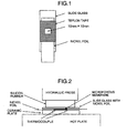
- FIG. 2 As shown in Fig. 2 , another nickel foil sheet B was placed on a ceramic plate to which a thermocouple was connected. On the ceramic plate with the nickel foil sheet B stuck thereon, a microporous membrane as a sample to be measured, which was immersed in a specified electrolyte for 3 hours in advance, was placed. Then, the slide with a nickel foil sheet stuck thereon and silicone rubber were placed in this order.
- the above ceramic plate was then set on a hot plate and heated up at a rate of 15°C/min under a pressure of 1.5 MPa by a hydraulic press.
- the change in impedance during the heat-up was measured while applying an alternating current 1V of 1 kHz.
- the shutdown speed was obtained as follows using the above measurements.
- a graph was prepared by plotting temperature in the horizontal axis and Log (Impedance) in the longitudinal axis, a tangent was drawn to the curve at a point where the impedance was 100 ⁇ , and the temperature during shutdown was determined using the points where the tangent intersects 1 ⁇ and 1000 ⁇ .
- Temperature during shutdown °C temperature at which the tangent intersects 1000 ⁇ °C - temperature at which the tangent intersects 1 ⁇ °C
- composition of the specified electrolyte was as follows.
- composition of electrolyte LiBF 4 was dissolved in the above solvent so that the concentration was 1 mol/liter and then trioctyl phosphate was added so that the concentration was 0.5% by weight.
- the intrinsic viscosity [ ⁇ ] of polyolefin as a raw material and that of the membrane were determined by measuring the intrinsic viscosities [ ⁇ ] in decalin solvent at 135°C in accordance with ASTM D4020.
- a microporous membrane was put between aluminum electrodes 4 cm in diameter and a load of 15 g was applied to them.
- the microporous membrane together with the aluminum electrodes were connected to a withstand voltage tester (TOS9201) manufactured by KIKUSUI ELCTRONICS CORP. to measure the withstand voltage.
- TOS9201 manufactured by KIKUSUI ELCTRONICS CORP.
- the measurement was conducted while applying an alternating voltage (60 Hz) at a rate of 1.0 KV/sec, and the voltage at which short-circuit occurred was defined as the measured value of the withstand voltage of the microporous membrane.
- the withstand voltage in terms of 20 ⁇ m was determined by multiplying the measured value by 20 ( ⁇ m)/membrane thickness ( ⁇ m).
- electrodes and an electrolyte were prepared as follows.
- the coating was conducted so that the amount of the active material for the negative electrode was 106 g/m 2 and the bulk density of the active material was 1.35 g/cm 3 .
- the copper foil having been coated with the active materials were cut to the battery width into a strip.
- Microporous membrane separators, a strip positive electrode and a strip negative electrode to be evaluated were prepared, and a layered structure of electrode plates was prepared by superposing the strip negative electrode, one of the separators, the strip positive electrode and the other separator in this order and spirally winding the superimposed material several times.
- the electrode-plate layered structure was pressed to be flat and contained in an aluminum container, and an aluminum lead was led out from the anode current collector and welded to the cap of the battery, while a nickel lead was led out from the cathode current collector and welded to the bottom of the container to produce a jelly roll.
- the withstand voltage of the jelly roll was measured under the same conditions as in (14) and was defined as the battery withstand voltage.
- a lithium ion battery was prepared by injecting the above described nonaqueous electrolyte into the jelly roll prepared in (15) and sealing the opening.
- the battery was charged up to 4.2 V by applying a charge current of 1A and discharged to 3 V by applying a charge current of 1A under the temperature of 25°C. This charge-discharge operation was taken as a cycle and the cycle was repeated. The proportion of the battery capacity after 500 times of the cycle to the initial capacity (capacity retention) was defined as cycle performance.
- silica powder A which was prepared by a dry process and had an average dispersion particle size of 0.25 ⁇ m, a 95 vol% cumulative dispersion particle size of 0.45 ⁇ m, a 5 vol% cumulative dispersion particle size of 0.15 ⁇ m, a ratio of cumulative dispersion particle size of 3.0, an oil absorption of 240 ml/100 g and a primary particle size of 12 nm (see Table 1), 19.2% by weight of an ultra-high-molecular-weight polyethylene with [ ⁇ ] of 7.0 dl/g, 12.8% by weight of a high-density polyethylene with [ ⁇ ] of 2.8 dl/g and 48% by weight of dioctyl phthalate (DOP) were mixed and granulated.
- DOP dioctyl phthalate
- the granulated mixture was then kneaded and extruded with a twin-screw extruder equipped with a T die into a sheet 90 ⁇ m thick. From this molded sheet, DOP was extracted and removed with methylene chloride and the silica powder was also extracted and removed with sodium hydroxide to produce a microporous membrane. Two sheets of the microporous membranes were superposed, stretched lengthwise to 4.5 times while heating at 110°C, and stretched widthwise to 2.0 times while heating at 130°C. The physical properties of the resultant membrane are shown in Table 2. The chart of the temperature measured during shut down of the membrane is shown in Figs. 3 , 4 . The battery evaluation was also conducted using this membrane. The results of the battery evaluation are also shown in Table 2.
- silica powder A 20.6% by weight of silica powder A, which was the same as that used in Example 1, 10.2% by weight of an ultra-high-molecular-weight polyethylene with [ ⁇ ] of 11.5 dl/g, 10.2% by weight of a high-density polyethylene with [ ⁇ ] of 1.8 dl/g, 13.6% by weight of a linear low-density polyethylene with [ ⁇ ] of 1.8 dl/g, and 45.4% by weight of DOP were mixed and granulated. The granulated mixture was then kneaded and extruded with a twin-screw extruder equipped with a T die into a sheet 90 ⁇ m thick.
- silica powder A which was the same as that used in Example 1, 3.4% by weight of an ultra-high-molecular-weight polyethylene with [ ⁇ ] of 11.5 dl/g, 6.8% by weight of an ultra-high-molecular-weight polyethylene with [ ⁇ ] of 7.0 dl/g, 10.2% by weight of a low-density polyethylene with [ ⁇ ] of 3.8 dl/g, 13.6% by weight of a linear low-density polyethylene with [ ⁇ ] of 1.8 dl/g, and 45.4% by weight of DOP were mixed and granulated.
- the granulated mixture was then kneaded and extruded with a twin-screw extruder equipped with a T die into a sheet 90 ⁇ m thick. From this molded sheet, DOP was extracted and removed with methylene chloride and the silica powder was also extracted and removed with sodium hydroxide to produce a microporous membrane. Two sheets of the microporous membranes were superposed, stretched lengthwise to 5.0 times while heating at 115°C, and stretched widthwise to 2.0 times while heating at 120°C. The physical properties of the resultant membrane are shown in Table 2. The battery evaluation was also conducted using this membrane. The results of the battery evaluation are also shown in Table 2.
- silica powder A 20.6% by weight of silica powder A, which was the same as that used in Example 1, 10.2% by weight of an ultra-high-molecular-weight polyethylene with [ ⁇ ] of 5.5 dl/g, 10.2% by weight of a low-density polyethylene with [ ⁇ ] of 3.8 dl/g, 13.6% by weight of a linear low-density polyethylene with [ ⁇ ] of 1.8 dl/g, and 45.4% by weight of DOP were mixed and granulated. The granulated mixture was then kneaded and extruded with a twin-screw extruder equipped with a T die into a sheet 90 ⁇ m thick.
- a microporous membrane was produced in the same manner as in Example 5, except that silica powder B was used, which was prepared by a dry process and had an average dispersion particle size of 0.30 ⁇ m, a 95 vol% cumulative dispersion particle size of 0.50 ⁇ m, a 5 vol% cumulative dispersion particle size of 0.13 ⁇ m, a ratio of cumulative dispersion particle size of 3.8, oil absorption of 220 ml/100 g and a primary particle size of 20 nm (see Table 1).
- the physical properties of the resultant membrane are shown in Table 2.
- the battery evaluation was also conducted using this membrane. The results of the battery evaluation are also shown in Table 2.
- silica powder C which was prepared by a dry process and made hydrophobidized with dimethyldichlorosilane, having an average dispersion particle size of 0.27 ⁇ m, a 95 vol% cumulative dispersion particle size of 0.55 ⁇ m, a 5 vol% cumulative dispersion particle size of 0.16 ⁇ m, a ratio of cumulative dispersion particle size of 3.4, oil absorption of 280 ml/100 g and a primary particle size of 12 nm (see Table 1), 19.2% by weight of an ultra-high-molecular-weight polyethylene with [ ⁇ ] of 7.0 dl/g, 12.8% by weight of a high-density polyethylene with [ ⁇ ] of 2.8 dl/g and 48% by weight of dioctyl phthalate (DOP) were mixed using Henschel mixer. The mixture was then kneaded and extruded with a twin-screw extruder, cooled, and palletized with pelletizer into a pellet material.
- DOP di
- This pellet material was kneaded and extruded with a twin-screw extruder equipped with a T die into a sheet 90 ⁇ m thick in the same manner as in Example 1. From this molded sheet, DOP was extracted and removed with methylene chloride and the silica powder was also extracted and removed with sodium hydroxide to produce a microporous membrane. Two sheets of the microporous membranes were superposed, stretched lengthwise to 4.5 times while heating at 110°C, and stretched widthwise to 2.0 times while heating at 130°C. The physical properties of the resultant membrane are shown in Table 2.
- a microporous membrane was produced in the same manner as in Example 1, except that silica powder D was used, which was prepared by a wet process, ground and classified, and had an average dispersion particle size of 0.60 ⁇ m, a 95 vol% cumulative dispersion particle size of 0.85 ⁇ m, a 5 vol% cumulative dispersion particle size of 0.42 ⁇ m, a ratio of cumulative dispersion particle size of 2.0, oil absorption of 200 ml/100 g and a primary particle size of 15 nm (see Table 1).
- the physical properties of the resultant membrane are shown in Table 2.
- the battery evaluation was also performed using this membrane. The results of the battery evaluation are also shown in Table 2.
- a microporous membrane was produced in the same manner as in Example 5, except that silica powder E was used, which was prepared by a wet process, ground and classified, and had an average dispersion particle size of 0.80 ⁇ m, a 95 vol% cumulative dispersion particle size of 2.38 ⁇ m, a 5 vol% cumulative dispersion particle size of 0.49 ⁇ m, a ratio of cumulative dispersion particle size of 4.9, oil absorption of 200 ml/100 g and a primary particle size of 15 nm (see Table 1).
- the physical properties of the resultant membrane are shown in Table 2.
- the battery evaluation was also conducted using this membrane. The results of the battery evaluation are also shown in Table 2.
- a microporous membrane was produced in the same manner as in Example 7 using the same silica powder E as used in Example 11.
- the physical properties of the resultant membrane are shown in Table 2.
- a microporous membrane was produced in the same manner as in Example 5, except that silica powder F was used, which was prepared by a wet process, ground and classified, and had an average dispersion particle size of 1.70 ⁇ m, a 95 vol% cumulative dispersion particle size of 4.32 ⁇ m, a 5 vol% cumulative dispersion particle size of 0.64 ⁇ m, a ratio of cumulative dispersion particle size of 6.8, oil absorption of 200 ml/100 g and a primary particle size of 15 nm (see Table 1).
- the physical properties of the resultant membrane are shown in Table 2.
- a microporous membrane was produced in the same manner as in Example 1, except that silica powder G was used, which was prepared by a wet process and had an average dispersion particle size of 7.10 ⁇ m, a 95 vol% cumulative dispersion particle size of 10.10 ⁇ m, a 5 vol% cumulative dispersion particle size of 2.5 ⁇ m, a ratio of cumulative dispersion particle size of 4.0, oil absorption of 190 ml/100 g and a primary particle size of 20 nm (see Table 1).
- the physical properties of the resultant membrane are shown in Table 2.
- the chart of the temperature measured during shut down of the membrane is shown in Figs. 3 , 5 .
- the battery evaluation was also conducted using this membrane. The results of the battery evaluation are also shown in Table 2.
- a microporous membrane was produced in the same manner as in Example 1, except that silica powder H was used, which was prepared by a wet process and had an average dispersion particle size of 2.08 ⁇ m, a 95 vol% cumulative dispersion particle size of 6.40 ⁇ m, a 5 vol% cumulative dispersion particle size of 0.48 ⁇ m, a ratio of cumulative dispersion particle size of 13.3, oil absorption of 220 ml/100 g and a primary particle size of 15 nm (Nipsil N-41 manufactured by TOSOH SILICA CORPORATION) (see Table 1). The physical properties of the resultant membrane are shown in Table 2.
- a microporous membrane was produced in the same manner as in Example 5, except that silica powder I was used, which was prepared by a wet process and had an average dispersion particle size of 0.71 ⁇ m, a 95 vol% cumulative dispersion particle size of 14.14 ⁇ m, a 5 vol% cumulative dispersion particle size of 0.49 ⁇ m, a ratio of cumulative dispersion particle size of 28.9, oil absorption of 240 ml/100 g and a primary particle size of 20 nm (Nipsil LP manufactured by TOSOH SILICA CORPORATION) (see Table 1).
- the physical properties of the resultant membrane are shown in Table 2.
- the battery evaluation was also conducted using this membrane. The results of the battery evaluation are also shown in Table 2.
- a microporous membrane was produced in the same manner as in Example 5, except that silica powder J was used, which was prepared by a wet process and had an average dispersion particle size of 5.32 ⁇ m, a 95 vol% cumulative dispersion particle size of 16.26 ⁇ m, a 5 vol% cumulative dispersion particle size of 0.49 ⁇ m, a ratio of cumulative dispersion particle size of 33.2, oil absorption of 240 ml/100 g and a primary particle size of 16 nm (Nipsil VN manufactured by TOSOH SILICA CORPORATION) (see Table 1). The physical properties of the resultant membrane are shown in Table 2.
- the gel sheet was then introduced into a simultaneous biaxial tenter stretching machine and subjected to biaxial stretching at a stretching ratio of 7 ⁇ 7 while heating at 115°C. Subsequently, the stretched sheet was sufficiently immersed in methylene chloride to extract and remove liquid paraffin, thereby producing a microporous membrane.
- the physical properties of the resultant membrane are shown in Table 2.
- the battery evaluation was also conducted using this membrane. The results of the battery evaluation are also shown in Table 2.
- the thin polyolefin microporous membrane excellent in permeability, high strength and safety according to the present invention is preferably used for electronic components, particularly as a separator for nonaqueous electrolyte batteries.
- the microporous membrane is particularly suitably used as a separator for high-capacity nonaqueous electrolyte batteries that is required to be thin. Using this microporous membrane as a separator makes it possible to obtain non-aqueous electrolyte batteries having high capacity, long life and high safety.
Description
- The present invention relates to a polyolefin microporous membrane that has a good permeability and is highly strong and safe and a method for producing the membrane. In particular, the present invention relates to a polyolefin microporous membrane that is useful as electronic components, particularly a separator for high-capacity, long-life nonaqueous electrolyte batteries, a method for producing the membrane, and a nonaqueous electrolyte battery.
- Polyolefin microporous membranes have been used so far as microfiltration membranes, battery separators, or capacitor separators. Particularly in recent years they have been used very often as separators for lithium ion secondary batteries. Currently, with the increase in power consumption, high-capacity, high-power and long-life lithium ion secondary batteries have been required.
- In the circumstances, separators for lithium ion secondary batteries are required to have high permeability in addition to making the batteries thinner. To obtain a high-capacity battery, it is effective to decrease the thickness of the battery separator while increasing the amount of active materials for positive and negative electrodes. To obtain a high-power battery, it is necessary to allow ions to pass through the battery separator all at once. To allow a large amount of ions to pass through the battery separator at a time, it is effective to increase the size of pores which ions pass through.
- To obtain a long-life battery, it is required to make the pores of the battery separator less likely to be clogged with impurities resulting from repeating operations of charging and discharging. In the separator having a large pore size, clogging with impurities is less likely to occur in the pores, and the battery capacity is less likely to be lowered. One index of battery life is, for example, cycle performance. The term "cycle performance" herein used means the battery capacity retention, relative to the initial capacity, when charge-discharge operations are repeated. The higher cycle performance becomes, the longer battery life becomes.
- When the above described things are taken into consideration, a microporous membrane which is thin and has a large pore size is useful as a separator of high permeability.
- Not only improving battery performance but also high strength and high safety of batteries have been required for suppressing the decrease in safety caused by making the batteries thinner. The term "safety" herein used is described from two aspects. One aspect of safety is the shutdown performance of separators. The separator's shutdown performance is such that when the inside of a battery is overheated, the separator is fused to serve as a coating to cover the battery electrodes, whereby current is cut off and the safety of the battery is ensured as long as the coating exists stably. One factor that contributes to the shutdown performance is pore size distribution. A separator having a narrow pore size distribution has excellent shutdown performance, since pore blocking occurs at a time when the temperature inside the battery reaches the melting point of the separator.
- Another aspect of safety is the withstand voltage of separators. The withstand voltage is the separator's insulating performance in terms of voltage that allows the separator to exist as an insulator between electrodes without causing short circuit between the electrodes. As the separator becomes thinner, the distance between the electrodes becomes smaller. Therefore, the separator is required to have a higher withstand voltage. It is conceivable that the pore size largely contributes to the separator's withstand voltage. The presence of extremely large pore size portion is more likely to cause a short circuit at lower voltages.
- Specifically, in a separator for high-capacity lithium ion secondary batteries, its thickness is required to be decreased and its pore size is required to be suitably large so that a high permeability could be ensured. Further, to allow the separator to have a high withstand voltage and excellent shutdown performance, a microporous membrane having a narrow pore size distribution is needed.
- As one of methods for producing a microporous membrane, a phase separation method is well known. In this production method, a resin and a plasticizer are blended at high temperatures to a homogeneous state, then quenched to cause phase separation between the resin phase and the plasticizer phase, and the plasticizer is extracted and removed to obtain a microporous membrane in which the portions of the plasticizer are pores in communication with each other.
- There have been disclosed techniques for producing a microporous membrane by a phase separation method, as represented by Japanese Patent No.
3347835 2657430 - On the other hand, there have been disclosed techniques for obtaining a microporous membrane having a large pore size and excellent permeability, in which a microporous membrane is obtained by kneading an inorganic powder such as silica fine particle, together with a polyolefin resin and a plasticizer and molding the same into a film and then extracting the plasticizer and the inorganic powder from the film (for example, see
JP-B-58-19689 2835365 JP-A-2002-88188 3121047 - In the light of the above-mentioned issues, in order to obtain a microporous membrane which has a moderately large pore size and a narrow pore size distribution, and thereby being useful as a separator for high-capacity lithium ion secondary batteries, it is effective to use an inorganic powder which is dispersed in a molten mixed material with its particle size kept moderate and has a narrow particle size distribution.
-
JP-B-58-19689 2835365 -
JP-A-2002-88188 - Japanese Patent No.
3121047 -
JP 63251436 -
US 4,833,172 discloses a precursor microporous material comprising a matrix consisting essentially of linear ultrahigh molecular weight polyolefin, a large proportion of finely divided water-insoluble siliceous filler, and interconnecting pores wherein the precursor is stretched to increase the porosity and provide regions of stretch-induced molecularly oriented polymer in the matrix. -
JP 2001081221 - As described so far, a microporous membrane for electronic components which is highly strong and safe and has high permeability when a separator is made thinner, a method for producing such a microporous membrane, and nonaqueous electrolyte batteries which use the separator having these characteristics, and thereby possessing high-capacity, long life and high safety have not been obtained.
- Accordingly, an object of the present invention is to provide a polyolefin microporous membrane that has a good permeability and is highly strong and safe. Another object of the present invention is to provide a polyolefin microporous membrane that is useful as electronic components, particularly a separator for high-capacity, long-life nonaqueous electrolyte batteries and a method for producing the same. Still another object of the present invention is to provide a nonaqueous electrolyte battery.
- After directing tremendous research efforts towards accomplishing the above described objects, the present inventors have found that a polyolefin microporous membrane having a narrow pore size distribution, while keeping the pore size moderate, and a high piercing strength exhibits a high permeability and high safety when used as a separator. In particular, it is useful as electronic components, particularly a separator for high-capacity nonaqueous electrolyte batteries. The present inventors have also found that use of a separator having such characteristics makes it possible to obtain a high-capacity, long-life and highly safe nonaqueous electrolyte battery.
- The present inventors have also found that it is essential, in the method for producing a polyolefin microporous membrane that is highly permeable, highly strong and highly safe, to use an inorganic powder that has a narrow particle size distribution and is dispersible with its particle size kept appropriate.
As a result, the present inventors have accomplished the present invention. - Specifically, the attributes of the present invention are as follows:
- 1. A polyolefin microporous membrane having a membrane thickness of 1 to 30 µm, a void content of 30 to 60%, a gas transmission rate of 5000 to 25000 sec/m3 (50 to 250 sec/100 cc), a piercing strength of 3.5 to 20.0 N/20 µm, a maximum pore size determined by the bubble point method of 0.08 to 0.20m, and a ratio of the maximum pore size to the average pore size (the maximum pore size/the average pore size) of 1.00 to 1.40 wherein the void content is calculated from the following equation: void content (%) = [{volume (cm3) - (mass (g)/density of polyethylene (g/cm3))}/volume (cm3)] x 100; the gas transmission rate is measured in accordance with JIS p-8117; the piercing strength is measured under the conditions where the radius of curvature of the needle is 0.5 mm and the piercing speed is 2 mm/sec; and the average pore size is measured by the half-dry method.
- 2. Use of the polyolefin microporous membrane as defined above, in electronic components.
- 3. Use of the polyolefin microporous membrane as defined above as a polyolefin separator for nonaqueous electrolyte batteries.
- 4. A nonaqueous electrolyte battery comprising a separator, characterized in that the polyolefin microporous membrane as defined above is used as the separator.
- 5. A method for producing a polyolefin microporous membrane as defined above comprising: providing a mixture of polyolefin resin, a plasticizer and an inorganic powder wherein in the total amount of these three components, the content of the polyolefin resin is 10 to 50 % by weight, the content of the plasticizer is 30 to 70 % by weight and the content of the inorganic powder is 5 to 40 % by weight; molding said mixture into a sheet while kneading and heat melting the mixture; extracting and removing the plasticizer and the inorganic powder from the sheet, respectively; and stretching the sheet at least uniaxially, wherein the inorganic powder has an average dispersion particle size of 0.01 to 5 µm and the ratio of the 95 vol% cumulative dispersion particle size and the 5 vol% cumulative dispersion particle size is 1.0 to 10.0, wherein the average dispersion particle size of the inorganic powder is measured using a laser diffraction particle size analyser under the following conditions: solvent of 86.4% ethanol, 7.3% methanol, water 6.3%; dispersion conditions of 40 VV ultrasonics for 10 minutes while stirring at 200 rpm; set value of refractive index of silica: real part 1.40, imaginary part 0; measuring temperature of 25°C.
- 6. The method as defined above, wherein the inorganic powder is silica powder.
- 7. The method as defined above, wherein the inorganic powder is silica powder prepared by a dry process.
- According to the present invention, a microporous membrane excellent in permeability, strength and safety can be provided. Further, a microporous membrane for use in electronic components can be provided, in particular, a polyolefin separator for nonaqueous electrolyte batteries which is useful as a separator for high-capacity, long-life nonaqueous electrolyte batteries can be provided. The microporous membrane according to the present invention can exhibit the above described effects even when its thickness is decreased compared with the thickness of conventional microporous membranes. Use of this microporous membrane as a separator makes it possible to obtain nonaqueous electrolyte batteries that have high-capacity, long-life and high safety.
-
-
Fig. 1 is a plan view showing a slide glass with a nickel foil which is used when measuring fuse temperatures and short temperatures; -
Fig. 2 is a schematic drawing of an apparatus for measuring fuse temperatures and short temperatures; -
Fig. 3 is a graph showing the transition in impedance of Example 1 and that of Comparative Example 1; -
Fig. 4 is an enlarged view of the impedance of Example 1; and -
Fig. 5 is an enlarged view of the impedance of Comparative Example 1. - The present invention will be described below in detail with respect to its preferred embodiments.
- The membrane thickness of a microporous membrane according to the present invention is 1 to 30 µm, preferably 1 to 27 µm, more preferably 1 to 25 µm, further more preferably 1 to 22 µm and most preferably 1 to 20 µm. If the membrane thickness is smaller than 1 µm, the mechanical strength and the safety at the time of shutdown are both worse, while if the membrane thickness is greater than 30 µm, the permeability is lowered, which results in an inferior separator for high-capacity batteries.
- The void content of the microporous membrane is 30 to 60% and preferably 35 to 55%. If the void content is lower than 30%, the permeability is worse, while if the void content is higher than 60%, the mechanical strength and the safety at the time of shutdown are both worse.
- The gas transmission rate of the microporous membrane is 50 to 250 sec/100 cc, preferably 50 to 200 sec/100 cc and more preferably 50 to 150 sec/100 cc. If the gas transmission rate is lower than 50 sec/100 cc, the safety at the time of shutdown is worse, while if the gas transmission rate is higher than 250 sec/100 cc, the permeability is worse.
- The piercing strength of the microporous membrane in terms of 20 µm is 3.5 to 20.0 N and preferably 4.0 to 20.0 N. If the piercing strength in terms of 20 µm is lower than 3.5 N, the membrane strength is low, the membrane is more likely to be torn, and the membrane is inferior in safety.
- The maximum pore size of the microporous membrane obtained by the bubble point method is 0.08 to 0.20 µm, preferably 0.09 to 0.20 µm, more preferably 0.10 to 0.20 µm and most preferably 0.10 to 0.15 µm. If the maximum pore size is smaller than 0.08 µm, the membrane is inferior in permeability, while if the maximum pore size is larger than 0.20 µm, the membrane is inferior in both safety at the time of shutdown and withstand voltage.
- The ratio of the average pore size to the maximum pore size is 1.00 to 1.40. If the ratio is larger than 1.40, the pore size distribution is wide, the pore size is non-uniform, and the safety at the time of shutdown and withstand voltage are inferior.
- Further, the temperature range during shutdown of a microporous membrane according to the present invention is preferably 7°C or lower, more preferably 5°C or lower, and most preferably 4°C or lower. From the viewpoint of security at the time of shutdown, the temperature from the initiation of shutdown to the completion of current interruption is preferably 5°C or lower. Higher safety is ensured when the temperature difference between the time when the membrane starts to melt and the time when shutdown is completed is smaller and the length of time spent in the same is shorter.
- As an index of permeability, the ratio of gas transmission rate to polymer content (= 100 - void content) (that is, gas transmission rate/polymer content) can be used. Microporous membranes in which the ratio is low have a high permeability even if they contain a large amount of polymer, and they are useful as a highly permeable and safe separator.
- From the viewpoint of permeability and safety, preferably the ratio of gas transmission rate to polymer content is 2.5 or lower, more preferably 2.3 or lower, and most preferably 2.0 or lower.
- The withstand voltage in terms of 20 µm is, considering the suppression of electrical short when high voltage is applied, preferably 0.8 KV or higher, more preferably 1.0 KV or higher, and most preferably 1.2 KV or higher.
- One example of the methods for producing a microporous membrane according to the present invention is shown by the following steps (a) to (e):
- (a) a step of mixing a polyolefin resin, a plasticizer, an inorganic powder and additives and granulating the mixture in a Henschel mixer or the like;
- (b) a step of melt-kneading the mixture prepared in the step (a) on an extruder with a T die mounted on its leading edge;
- (c) a step of molding the kneaded material obtained in the step (b) into a sheet by extruding the kneaded material from the T die, rolling the extruded material from both sides with a heat roll, followed by cooling;
- (d) a step of extracting and removing the plasticizer and inorganic powder from the molded product in the form of a sheet, followed by drying; and
- (e) a step of stretching the molded product in the form of a sheet at least axially and heat treating the same.
- Examples of inorganic powders usable in the step (a) of the production method of the present invention include: silica, calcium silicate, aluminum silicate, alumina, calcium carbonate, magnesium carbonate, kaolin clay, talc, titanium oxide, carbon black and diatomaceous earth. Either one of them alone or several of them in the form of a mixture may be used. The inorganic powder preferably used in the present invention is silica, particularly preferably silica prepared by a dry process.
- The average dispersion particle size of the inorganic powder is 0.01 to 5 µm, preferably 0.05 to 3 µm, and more preferably 0.1 to 1 µm. Inorganic fine particles, represented by silica, have a strong aggregation force and usually form aggregates. Therefore, they are less likely to exist in the state of the primary particle (one fine particle not forming an aggregate). The term average of dispersion particle size referred to herein does not mean the average of primary particle size, but that of inorganic particles in the aggregated and dispersed state. The important thing in a fine particle mixture system is the state in which fine particles are dispersed. If the average dispersion particle size is smaller than 0.01 µm, the fine particles are dispersed in too fine a state when used in the production of a microporous membrane. This results in a microporous membrane having a poor permeability. On the other hand, if the average dispersion particle size is larger than 5 µm, the inorganic fine particles exist in too large a state in the membrane when used in the production of a microporous membrane. This results in a microporous membrane having a non-uniform structure and not having high strength and safety.
- The ratio of the 95 vol% cumulative dispersion particle size of the inorganic powder to the 5 vol% cumulative dispersion particle size of the inorganic powder (that is, the former value/the latter value) is 1.0 to 10.0, preferably 1.0 to 7.0 and more preferably 1.0 to 5.0. The term "5 vol% cumulative dispersion particle size" means the particle size at which the cumulative volume fraction of particles integrated from the smaller particle size to the larger particle size reaches 5% in the entire inorganic powder used. Likewise, the term "95 vol% cumulative dispersion particle size" means the particle size at which the cumulative volume fraction of particles integrated from the smaller particle size to the larger particle size reaches 95% in the entire inorganic powder used. The cumulative dispersion particle size ratio shows the dispersed state of the inorganic fine particles at the time of measuring the average dispersion particle size. If the cumulative dispersion particle size ratio of the inorganic powder is more than 10.0, the dispersion of the inorganic particles in the membrane is not uniform, whereby the membrane structure is not uniform and a highly strong and safe microporous membrane cannot be obtained.
- A method for producing a silica powder, as a typical example of inorganic powder, will be described below. Methods for synthesizing a silica powder are generally classified into three major groups according to the characteristics: a dry method in which the synthesis is performed under high temperatures of 100°C or more; a wet method in which sodium silicate, mineral acid and salts are reacted in an aqueous solution; and an aerogel method in which sodium silicate and mineral acid are reacted to form silica gel, water in the gel is then replaced with an organic solvent, and the resultant organogel is heat treated under pressure.
- As the dry method, a combustion method in which gasified silicon tetrachloride is burned in the air to obtain very fine silica particles is often used. Besides this combustion method, there is a heating method in which the SiO vapor obtained by heating silica sand and coke is oxidized in the air to obtain silica particles larger than those obtained by the combustion method.
- As the wet method, there are: a sedimentation method in which the reaction of sodium silicate and a mineral acid is conducted while changing the pH of the reaction solution to that of alkaline solution, thereby increasing the growth rate of silica particles so that the silica particles are aggregated into a flock to be settled down; and a gel method in which the reaction of sodium silicate and a mineral acid is conducted while changing the pH of the reaction solution to that of acidic solution, thereby suppressing the growth rate of silica particles and allowing silica particles to be aggregated so that the silica is aggregated and the reaction solution is gelled.
- In the present invention, silica synthesized by any one of the above described methods can be used; however, considering the dispersion of the silica powder, silica synthesized by the dry method is preferably used. The reason is that in dry silica, the aggregation force among its particles is weak compared with wet silica, and therefore, the dry silica exhibits high dispersion properties in the mixing step (a) or in the melt-kneading step (b) using an extruder.
- Even in wet silica which has a stronger aggregation force compared with dry silica, if it is ground and classified after synthesized, silica having a small average dispersion particle size and a uniform particle size can be obtained. In wet silica, it is also preferred that such ground and classified silica is used.
- Silica with hydrophobic surface is also known which is obtained by subjecting the surface of synthesized silica to hydrophobic treatment. However, considering dispersion properties in a membrane, handling during production of membrane and cost, hydrophilic silica is preferable. The oil absorption of a silica powder is preferably 100 to 400 ml/100 g and more preferably 150 to 300 ml/100 g, considering the dispersion properties of the polyolefin resin and plasticizer used.
- The polyolefin resin used in the present invention may be composed of a single polyolefin or may be a polyolefin composition that includes several kinds of polyolefins. Examples of polyolefin usable in the present invention include: polyethylene, polypropylene and poly-4-methyl-1-pentene. Two or more kinds of these polyolefins may be used in the form of a blend. To realize a highly permeable microporous membrane, it is preferable to use polyethylene alone.
- Kinds of polyethylene usable in the present invention include: for example, high-density polyethylene with a density higher than 0.94 g/cm3; medium-density polyethylene with a density in the range of 0.93 to 0.94 g/cm3; and low-density polyethylene with a density lower than 0.93 g/cm3; and linear low-density polyethylene. To increase the membrane strength, it is preferable to use high-density polyethylene and medium-density polyethylene. Either high-density polyethylene or medium-density polyethylene alone or a mixture thereof may be used.
- To realize high strength of the microporous membrane, preferably 5 to 90% by weight, and considering the moldability, more preferably 10 to 80% by weight of ultra-high-molecular-weight polyethylene with an intrinsic viscosity [η] of about 5 to 20 dl/g is added. To obtain high permeability of the microporous membrane, preferably 10 to 95% by weight of high-density polyethylene is added.
- In terms of molecular weight distribution, polyethylene having a narrow molecular weight distribution prepared using a metallocene catalyst or polyethylene having a wide molecular weight distribution prepared by two-step polymerization can also be used.
- Kinds of polypropylene usable in the present invention include: for example, propylene homopolymer, ethylene-propylene random copolymer, and ethylene-propylene block copolymer. The content of ethylene in the total amount of polypropylene used is preferably 0 to 3 mol%, and the polypropylene used is preferably composed of propylene homopolymer alone. The [η] of the polypropylene used is preferably 1 to 25 dl/g and more preferably 2 to 7 dl/g.
- Examples of plasticizer usable in the present invention include: organic acid esters such as phthalate esters such as dioctyl phthalate, diheptyl phthalate and diburyl phthalate, adipate esters and glycerin esters; phosphate esters such as trioctyl phosphate; liquid paraffin; solid wax; and mineral oil. Taking into consideration the compatibility with polyethylene, phthalate esters are preferable. Either one of these plasticizers alone or a mixture thereof may be used.
- Regarding mixing ratio of the polyolefin resin, a plasticizer and an inorganic powder in the production method of the present invention, to increase the strength of the microporous membrane, the content of polyolefin resin in the total amount of these three components is preferably 10 to 50% by weight and more preferably 20 to 40% by weight. To obtain better moldability and suitable pore size of the microporous membrane, the content of plasticizer is preferably 30 to 70% by weight and more preferably 40 to 60% by weight. To obtain suitable pore size of the microporous membrane and increase the strength of the microporous membrane, the content of inorganic powder is preferably 5 to 40% by weight and more preferably 10 to 30% by weight.
- In addition to polyolefin, inorganic powder and plasticizer, various additives such as antioxidant, antistatic agent, ultraviolet absorber, lubricant or anti-blocking agent can also be added, if necessary, so long as the addition does not impair the effects of the present invention.
- A conventional mixing method with a blender such as Henschel mixer, V-blender, Proshear mixer or a ribbon blender can be sufficiently used for mixing the three components, polyolefin, inorganic powder and plasticizer.
- In the step (b), the mixture is kneaded with a melt-kneading equipment such as extruder or kneader. The resultant kneaded material is molded into a sheet by melt-molding using a T die. In this molding operation, it is preferable from the view point of dimensional stability to carry out molding via a gear pump and it is particularly preferable from the view point of dimensional stability to carry out molding while keeping the pressure before the gear pump constant.
- The step (c) may be conducted by: a cooling method by air; a cooling method in which the resin is brought into contact with the roll whose temperature is adjusted to 20 to 120°C lower than the resin temperature extruded from the T die; or a cooling method in which the resin is cooled while subjecting the resin to calendering-molding into a sheet with calender rolls whose temperature is adjusted to 20 to 120°C lower than the resin temperature extruded from the T die. It is preferable from the viewpoint of obtaining a membrane of a uniform thickness to adopt the cooling process in which the resin is cooled while subjecting the resin to calendering-molding into a sheet with calender rolls whose temperature is adjusted to 20 to 120°C lower than the resin temperature extruded from the T die. In this case, when the roll is used, it is preferred that the molding is carried out while keeping the distance between the T die and the point at which the rolls come into contact with the sheet within the range of 5 to 500 mm. The temperature of the resin extruded from the T die can be measured with a normal thermocouple thermometer by bringing the terminal of the thermocouple thermometer into contact with the extruded resin while avoiding the contact of the terminal with the die.
- In the step (d), the plasticizer and the inorganic powder in the membrane are extracted with a solvent. Examples of solvent usable for extraction of plasticizers include: for example, organic solvents such as methanol, ethanol, methyl ethyl ketone and acetone; ketones such as acetone and methyl ethyl ketone; ethers such as tetrahydrofuran; and halogenated hydrocarbons such as methylene chloride and 1,1,1-trichloroethane. Either any one of these solvents alone or a mixture thereof may be used. After extraction of the plasticizer, extraction of the inorganic powder is carried out. Examples of solvent usable for extraction of inorganic powder include alkaline aqueous solutions such as sodium hydroxide and potassium hydroxide.
- In the step (e), the aforementioned membrane from which the plasticizer and the inorganic powder have been extracted is stretched at least uniaxially. When stretching is performed uniaxially, either roll stretching or stretching using tenter may be used. In view of the increase in strength and the decrease in thickness of the microporous membrane, biaxial stretching is preferable. Further in view of the increase in strength and the decrease in thickness of the microporous membrane, the stretching rate of the membrane is preferably 6 times or greater in terms of area stretching rate and more preferably 8 times or greater. When biaxial stretching is carried out, either sequential biaxial stretching or simultaneous biaxial stretching may be used. Sequential biaxial stretching is preferably used to obtain a microporous membrane having a large pore size and high permeability. In this case, a single membrane or a plurality of superposed membranes can be stretched. From the viewpoint of obtaining a membrane having high strength, it is preferable to stretch a plurality of superposed membranes. Following the stretching or with an interval after the completion of the stretching, heat treatment such as heat set or thermal relaxation may be carried out.
- The present invention will be described below in further detail by Examples.
- Test methods used in Examples are as follows.
- Measurement was made under the following conditions using a laser diffraction particle size analyzer manufactured by Shimadzu Corporation. The median diameter obtained by the measurement was defined as the average dispersion particle size of the inorganic powder.
- Solvent: industrial alcohol, EKINEN F-8, manufactured by Japan Alcohol Trading
- Composition ... ethanol 86.4%, methanol 7.3%, water 6.3%
- Dispersing conditions: Exposed to 40 W ultrasonics for 10 minutes while stirring at 200 rpm and then measured.
- Set value of refractive index of silica: real part ... 1.40; imaginary part ... 0
- Measuring temperature: 25°C
- The ratio was calculated from the following equation using the values measured on the analyzer described in (1).
- The ratio of cumulative dispersion particle size = 95 vol% cumulative dispersion particle size/5 vol% cumulative dispersion particle size
- Measurement was made in accordance with JIS K5101-1991 using DOP.
- Measurement was made using a dial gauge (PEACOCK No. 25 manufactured by OZAKI MFG. CO., LTD.). Measurement was made at a plurality of points per sample and the average value of the measurements was used as the membrane thickness.
- A sample by 20 cm square was taken, and the void content was calculated from the following equation using the volume and mass of the sample.

- Measurement was made using a Gurley type gas transmission rate tester in accordance with JIS p-8117.
- The maximum piercing load (N) was measured by conducting piercing test using a handy compression testing machine, KES-G5, manufactured by KATO TECH CO., LTD. under the conditions: the radius of curvature of needle tip was 0.5 mm and the piercing speed was 2 mm/sec. The piercing strength in terms of 20 µm was obtained by multiplying the measured value by 20 (µm)/membrane thickness (µm).
- The maximum pore size was calculated in accordance with ASTM E-128-61 using the value of the bubble point in ethanol.
- The average pore size was calculated in accordance with ASTM F-316-86 using ethanol.
- The pore size ratio was determined from the following equation using the maximum pore size and the average pore size determined in (8) and (9).

- Measurement was made of resistance using an LCR meter AG-43 manufactured by Ando Electric Co., Ltd. and a cell shown in
Fig. 1 by applying an alternating current of 1 kHz and the electric resistance was calculated from the following equation.
- The measuring conditions were as follows. Electrolyte: a solution of 1 mol/liter lithium perchlorate in the mixture of propylene carbonate and diethoxyethane (50/50 vol%), Electrode: platinum black, Area of electrode plate: 0.785 cm2, Interelectrode distance: 3 mm
- As shown in
Fig. 1, 2 sheets of nickel foil 10 µm thick (A, B) were prepared, and one of the nickel foil sheets A was fixed on a slide and masked with a Teflon tape with its 10 mm by 10 mm square portion left unmasked - As shown in
Fig. 2 , another nickel foil sheet B was placed on a ceramic plate to which a thermocouple was connected. On the ceramic plate with the nickel foil sheet B stuck thereon, a microporous membrane as a sample to be measured, which was immersed in a specified electrolyte for 3 hours in advance, was placed. Then, the slide with a nickel foil sheet stuck thereon and silicone rubber were placed in this order. - The above ceramic plate was then set on a hot plate and heated up at a rate of 15°C/min under a pressure of 1.5 MPa by a hydraulic press. The change in impedance during the heat-up was measured while applying an alternating current 1V of 1 kHz.
- The shutdown speed was obtained as follows using the above measurements. A graph was prepared by plotting temperature in the horizontal axis and Log (Impedance) in the longitudinal axis, a tangent was drawn to the curve at a point where the impedance was 100 Ω, and the temperature during shutdown was determined using the points where the tangent intersects 1 Ω and 1000 Ω.

- The composition of the specified electrolyte was as follows.
- Composition of solvent (volume ratio): propylene carbonate/ethylene carbonate/δ - butyrolactone = 1/1/2
- Composition of electrolyte: LiBF4 was dissolved in the above solvent so that the concentration was 1 mol/liter and then trioctyl phosphate was added so that the concentration was 0.5% by weight.
- The intrinsic viscosity [η] of polyolefin as a raw material and that of the membrane were determined by measuring the intrinsic viscosities [η] in decalin solvent at 135°C in accordance with ASTM D4020.
- A microporous membrane was put between aluminum electrodes 4 cm in diameter and a load of 15 g was applied to them. The microporous membrane together with the aluminum electrodes were connected to a withstand voltage tester (TOS9201) manufactured by KIKUSUI ELCTRONICS CORP. to measure the withstand voltage. The measurement was conducted while applying an alternating voltage (60 Hz) at a rate of 1.0 KV/sec, and the voltage at which short-circuit occurred was defined as the measured value of the withstand voltage of the microporous membrane. The withstand voltage in terms of 20 µm was determined by multiplying the measured value by 20 (µm)/membrane thickness (µm).
- To carry out evaluations of battery, electrodes and an electrolyte were prepared as follows.
- 100 parts by weight of lithium cobalt hybrid oxide LiCoO2 as a positive active material, 2.5 parts by weight of flake graphite and 2.5 parts by weight of acetylene black as conducting agents, and 3.5 parts by weight of polyvinylidene fluoride as a binder, were dispersed in N-methylpyrrolidone (NMP) to prepare a slurry. The slurry was coated on both sides of an aluminum foil 20 µm thick, which is to be an anode current collector, with a die coater, dried at 130°C for 3 minutes, and compression molded with a roll press equipment. The coating was conducted so that the amount of the active material for the positive electrode was 250 g/m2 and the bulk density of the active material was 3.00 g/cm3. The aluminum foil having been coated with the active materials were cut to the battery width into a strip.
- 90 parts by weight of graphitized mesophase-pitch-based carbon fiber (MCF) and 10 parts by weight of flake graphite, as negative active materials, 1.4 parts by weight of ammonium salt of carboxymethylcellulose and 1.8 parts by weight of styrene-butadiene copolymer latex, as binders, were dispersed in purified water to prepare a slurry. The slurry was coated on both sides of copper foil 12 µm thick, which is to be a cathode current collector, with a die coater, dried at 120°C for 3 minutes, and compression molded with a roll press equipment. The coating was conducted so that the amount of the active material for the negative electrode was 106 g/m2 and the bulk density of the active material was 1.35 g/cm3. The copper foil having been coated with the active materials were cut to the battery width into a strip.
- A nonaqueous electrolyte was prepared by dissolving LiPF6 as a solute in a mixed solvent of ethylene carbonate : ethyl methyl carbonate = 1 : 2 (volume ratio) so that the concentration of LiPF6 was 1.0 mol/liter.
- Microporous membrane separators, a strip positive electrode and a strip negative electrode to be evaluated were prepared, and a layered structure of electrode plates was prepared by superposing the strip negative electrode, one of the separators, the strip positive electrode and the other separator in this order and spirally winding the superimposed material several times. The electrode-plate layered structure was pressed to be flat and contained in an aluminum container, and an aluminum lead was led out from the anode current collector and welded to the cap of the battery, while a nickel lead was led out from the cathode current collector and welded to the bottom of the container to produce a jelly roll.
- The withstand voltage of the jelly roll was measured under the same conditions as in (14) and was defined as the battery withstand voltage.
- A lithium ion battery was prepared by injecting the above described nonaqueous electrolyte into the jelly roll prepared in (15) and sealing the opening.
- The battery was charged up to 4.2 V by applying a charge current of 1A and discharged to 3 V by applying a charge current of 1A under the temperature of 25°C. This charge-discharge operation was taken as a cycle and the cycle was repeated. The proportion of the battery capacity after 500 times of the cycle to the initial capacity (capacity retention) was defined as cycle performance.
- 20% by weight of silica powder A, which was prepared by a dry process and had an average dispersion particle size of 0.25 µm, a 95 vol% cumulative dispersion particle size of 0.45 µm, a 5 vol% cumulative dispersion particle size of 0.15 µm, a ratio of cumulative dispersion particle size of 3.0, an oil absorption of 240 ml/100 g and a primary particle size of 12 nm (see Table 1), 19.2% by weight of an ultra-high-molecular-weight polyethylene with [η] of 7.0 dl/g, 12.8% by weight of a high-density polyethylene with [η] of 2.8 dl/g and 48% by weight of dioctyl phthalate (DOP) were mixed and granulated. The granulated mixture was then kneaded and extruded with a twin-screw extruder equipped with a T die into a sheet 90 µm thick. From this molded sheet, DOP was extracted and removed with methylene chloride and the silica powder was also extracted and removed with sodium hydroxide to produce a microporous membrane. Two sheets of the microporous membranes were superposed, stretched lengthwise to 4.5 times while heating at 110°C, and stretched widthwise to 2.0 times while heating at 130°C. The physical properties of the resultant membrane are shown in Table 2. The chart of the temperature measured during shut down of the membrane is shown in
Figs. 3 ,4 . The battery evaluation was also conducted using this membrane. The results of the battery evaluation are also shown in Table 2. - Two sheets of the membranes, where the silica powder had been extracted, produced in the same manner as in Example 1 were superposed, stretched lengthwise to 5.0 times while heating at 115°C, and stretched widthwise to 2.2 times while heating at 133°C. The physical properties of the resultant membrane are shown in Table 2.
- Two sheets of the membranes, where the silica powder had been extracted, produced in the same manner as in Example 1 were superposed, stretched lengthwise to 6.0 times while heating at 117°C, and stretched widthwise to 2.5 times while heating at 135°C. The physical properties of the resultant membrane are shown in Table 2.
- 20.6% by weight of silica powder A, which was the same as that used in Example 1, 10.2% by weight of an ultra-high-molecular-weight polyethylene with [η] of 11.5 dl/g, 10.2% by weight of a high-density polyethylene with [η] of 1.8 dl/g, 13.6% by weight of a linear low-density polyethylene with [η] of 1.8 dl/g, and 45.4% by weight of DOP were mixed and granulated. The granulated mixture was then kneaded and extruded with a twin-screw extruder equipped with a T die into a sheet 90 µm thick. From this molded sheet, DOP was extracted and removed with methylene chloride and the silica powder was also extracted and removed with sodium hydroxide to produce a microporous membrane. Two sheets of the microporous membranes were superposed, stretched lengthwise to 4.5 times while heating at 115°C, and stretched widthwise to 2.0 times while heating at 120°C. The physical properties of the resultant membrane are shown in Table 2.
- 20.6% by weight of silica powder A, which was the same as that used in Example 1, 3.4% by weight of an ultra-high-molecular-weight polyethylene with [η] of 11.5 dl/g, 6.8% by weight of an ultra-high-molecular-weight polyethylene with [η] of 7.0 dl/g, 10.2% by weight of a low-density polyethylene with [η] of 3.8 dl/g, 13.6% by weight of a linear low-density polyethylene with [η] of 1.8 dl/g, and 45.4% by weight of DOP were mixed and granulated. The granulated mixture was then kneaded and extruded with a twin-screw extruder equipped with a T die into a sheet 90 µm thick. From this molded sheet, DOP was extracted and removed with methylene chloride and the silica powder was also extracted and removed with sodium hydroxide to produce a microporous membrane. Two sheets of the microporous membranes were superposed, stretched lengthwise to 5.0 times while heating at 115°C, and stretched widthwise to 2.0 times while heating at 120°C. The physical properties of the resultant membrane are shown in Table 2. The battery evaluation was also conducted using this membrane. The results of the battery evaluation are also shown in Table 2.
- Two sheets of the membranes, where the silica powder had been extracted, produced in the same manner as in Example 5 were superposed, stretched lengthwise to 5.5 times while heating at 115°C, and stretched widthwise to 2.0 times while heating at 122°C. The physical properties of the resultant membrane are shown in Table 2.
- 20.6% by weight of silica powder A, which was the same as that used in Example 1, 10.2% by weight of an ultra-high-molecular-weight polyethylene with [η] of 5.5 dl/g, 10.2% by weight of a low-density polyethylene with [η] of 3.8 dl/g, 13.6% by weight of a linear low-density polyethylene with [η] of 1.8 dl/g, and 45.4% by weight of DOP were mixed and granulated. The granulated mixture was then kneaded and extruded with a twin-screw extruder equipped with a T die into a sheet 90 µm thick. From this molded sheet, DOP was extracted and removed with methylene chloride and the silica powder was also extracted and removed with sodium hydroxide to produce a microporous membrane. Two sheets of the microporous membranes were superposed, stretched lengthwise to 5.0 times while heating at 115°C, and stretched widthwise to 2.0 times while heating at 120°C. The physical properties of the resultant membrane are shown in Table 2.
- A microporous membrane was produced in the same manner as in Example 5, except that silica powder B was used, which was prepared by a dry process and had an average dispersion particle size of 0.30 µm, a 95 vol% cumulative dispersion particle size of 0.50 µm, a 5 vol% cumulative dispersion particle size of 0.13 µm, a ratio of cumulative dispersion particle size of 3.8, oil absorption of 220 ml/100 g and a primary particle size of 20 nm (see Table 1). The physical properties of the resultant membrane are shown in Table 2. The battery evaluation was also conducted using this membrane. The results of the battery evaluation are also shown in Table 2.
- 20% by weight of silica powder C, which was prepared by a dry process and made hydrophobidized with dimethyldichlorosilane, having an average dispersion particle size of 0.27 µm, a 95 vol% cumulative dispersion particle size of 0.55 µm, a 5 vol% cumulative dispersion particle size of 0.16 µm, a ratio of cumulative dispersion particle size of 3.4, oil absorption of 280 ml/100 g and a primary particle size of 12 nm (see Table 1), 19.2% by weight of an ultra-high-molecular-weight polyethylene with [η] of 7.0 dl/g, 12.8% by weight of a high-density polyethylene with [η] of 2.8 dl/g and 48% by weight of dioctyl phthalate (DOP) were mixed using Henschel mixer. The mixture was then kneaded and extruded with a twin-screw extruder, cooled, and palletized with pelletizer into a pellet material.
- This pellet material was kneaded and extruded with a twin-screw extruder equipped with a T die into a sheet 90 µm thick in the same manner as in Example 1. From this molded sheet, DOP was extracted and removed with methylene chloride and the silica powder was also extracted and removed with sodium hydroxide to produce a microporous membrane. Two sheets of the microporous membranes were superposed, stretched lengthwise to 4.5 times while heating at 110°C, and stretched widthwise to 2.0 times while heating at 130°C. The physical properties of the resultant membrane are shown in Table 2.
- A microporous membrane was produced in the same manner as in Example 1, except that silica powder D was used, which was prepared by a wet process, ground and classified, and had an average dispersion particle size of 0.60 µm, a 95 vol% cumulative dispersion particle size of 0.85 µm, a 5 vol% cumulative dispersion particle size of 0.42 µm, a ratio of cumulative dispersion particle size of 2.0, oil absorption of 200 ml/100 g and a primary particle size of 15 nm (see Table 1). The physical properties of the resultant membrane are shown in Table 2. The battery evaluation was also performed using this membrane. The results of the battery evaluation are also shown in Table 2.
- A microporous membrane was produced in the same manner as in Example 5, except that silica powder E was used, which was prepared by a wet process, ground and classified, and had an average dispersion particle size of 0.80 µm, a 95 vol% cumulative dispersion particle size of 2.38 µm, a 5 vol% cumulative dispersion particle size of 0.49 µm, a ratio of cumulative dispersion particle size of 4.9, oil absorption of 200 ml/100 g and a primary particle size of 15 nm (see Table 1). The physical properties of the resultant membrane are shown in Table 2. The battery evaluation was also conducted using this membrane. The results of the battery evaluation are also shown in Table 2.
- Two sheets of the membranes, where the silica powder had been extracted, produced in the same manner as in Example 11 were superposed, stretched lengthwise to 5.5 times while heating at 115°C, and stretched widthwise to 2.0 times while heating at 122°C. The physical properties of the resultant membrane are shown in Table 2.
- A microporous membrane was produced in the same manner as in Example 7 using the same silica powder E as used in Example 11. The physical properties of the resultant membrane are shown in Table 2.
- A microporous membrane was produced in the same manner as in Example 5, except that silica powder F was used, which was prepared by a wet process, ground and classified, and had an average dispersion particle size of 1.70 µm, a 95 vol% cumulative dispersion particle size of 4.32 µm, a 5 vol% cumulative dispersion particle size of 0.64 µm, a ratio of cumulative dispersion particle size of 6.8, oil absorption of 200 ml/100 g and a primary particle size of 15 nm (see Table 1). The physical properties of the resultant membrane are shown in Table 2.
- A microporous membrane was produced in the same manner as in Example 1, except that silica powder G was used, which was prepared by a wet process and had an average dispersion particle size of 7.10 µm, a 95 vol% cumulative dispersion particle size of 10.10 µm, a 5 vol% cumulative dispersion particle size of 2.5 µm, a ratio of cumulative dispersion particle size of 4.0, oil absorption of 190 ml/100 g and a primary particle size of 20 nm (see Table 1). The physical properties of the resultant membrane are shown in Table 2. The chart of the temperature measured during shut down of the membrane is shown in
Figs. 3 ,5 . The battery evaluation was also conducted using this membrane. The results of the battery evaluation are also shown in Table 2. - A microporous membrane was produced in the same manner as in Example 1, except that silica powder H was used, which was prepared by a wet process and had an average dispersion particle size of 2.08 µm, a 95 vol% cumulative dispersion particle size of 6.40 µm, a 5 vol% cumulative dispersion particle size of 0.48 µm, a ratio of cumulative dispersion particle size of 13.3, oil absorption of 220 ml/100 g and a primary particle size of 15 nm (Nipsil N-41 manufactured by TOSOH SILICA CORPORATION) (see Table 1). The physical properties of the resultant membrane are shown in Table 2.
- A microporous membrane was produced in the same manner as in Example 5, except that silica powder I was used, which was prepared by a wet process and had an average dispersion particle size of 0.71 µm, a 95 vol% cumulative dispersion particle size of 14.14 µm, a 5 vol% cumulative dispersion particle size of 0.49 µm, a ratio of cumulative dispersion particle size of 28.9, oil absorption of 240 ml/100 g and a primary particle size of 20 nm (Nipsil LP manufactured by TOSOH SILICA CORPORATION) (see Table 1). The physical properties of the resultant membrane are shown in Table 2. The battery evaluation was also conducted using this membrane. The results of the battery evaluation are also shown in Table 2.
- A microporous membrane was produced in the same manner as in Example 5, except that silica powder J was used, which was prepared by a wet process and had an average dispersion particle size of 5.32 µm, a 95 vol% cumulative dispersion particle size of 16.26 µm, a 5 vol% cumulative dispersion particle size of 0.49 µm, a ratio of cumulative dispersion particle size of 33.2, oil absorption of 240 ml/100 g and a primary particle size of 16 nm (Nipsil VN manufactured by TOSOH SILICA CORPORATION) (see Table 1). The physical properties of the resultant membrane are shown in Table 2.
- 60% by weight of an ultra-high-molecular-weight polyethylene with [η] of 13.1 dl/g and 40% by weight of a high-density polyethylene with [η] of 2.8 dl/g were dry blended with a tumble blender. 45% by weight of the resultant polyethylene mixture and 55% by weight of liquid paraffin were kneaded and extruded with a twin-screw extruder equipped with a T die into a gel sheet 1850 µm thick.
- The gel sheet was then introduced into a simultaneous biaxial tenter stretching machine and subjected to biaxial stretching at a stretching ratio of 7 × 7 while heating at 115°C. Subsequently, the stretched sheet was sufficiently immersed in methylene chloride to extract and remove liquid paraffin, thereby producing a microporous membrane. The physical properties of the resultant membrane are shown in Table 2. The battery evaluation was also conducted using this membrane. The results of the battery evaluation are also shown in Table 2.
- 2% by weight of an ultra-high-molecular-weight polyethylene with [η] of 7.0 dl/g, 13% by weight of a high-density polyethylene with [η] of 3.6 dl/g and 85% by weight of liquid paraffin were mixed, and the mixture was filled into an autoclave and stirred at 200°C for 90 minutes to obtain a polymer solution. The polymer solution was subjected to biaxial stretching at a stretching ratio of 5 × 5 in the same manner as in Comparative Example 3 to obtain a membrane from which liquid paraffin had been extracted. This membrane was then stretched widthwise to 1.5 time while heating at 95°C. The physical properties of the resultant membrane are shown in Table 2. The battery evaluation was also conducted using this membrane. The results of the battery evaluation are also shown in Table 2.
[Table 1] Characteristics of silica powder Average dispersion particle size (µm) 95 vol% cumulative dispersion particle size (µm) 5 vol% cumulative dispersion particle size (µm) Ratio of cumulative dispersion particle size (-) Oil absorption (ml/100g) Primary particle size (nm) Silica A 0.25 0.45 0.15 3.0 240 12 Silica B 0.30 0.50 0.13 3.8 220 20 Silica C 0.27 0.55 0.16 3.4 280 12 Silica D 0.60 0.85 0.42 2.0 200 15 Silica E 0.80 2.38 0.49 4.9 200 15 Silica F 1.70 4.32 0.64 6.8 200 15 Silica G 7.10 10.10 2.50 4.0 190 20 Silica H 2.08 6.40 0.48 13.3 220 15 Silica I 0.71 14.14 0.49 28.9 240 20 Silica J 5.32 16.26 0.49 33.2 240 16 

- The thin polyolefin microporous membrane excellent in permeability, high strength and safety according to the present invention is preferably used for electronic components, particularly as a separator for nonaqueous electrolyte batteries. The microporous membrane is particularly suitably used as a separator for high-capacity nonaqueous electrolyte batteries that is required to be thin. Using this microporous membrane as a separator makes it possible to obtain non-aqueous electrolyte batteries having high capacity, long life and high safety.
Claims (7)
- A polyolefin microporous membrane having a membrane thickness of 1 to 30 µm, a void content of 30 to 60% a piercing strength of 3.5 to 20.0 N/(20µm), a maximum pore size determined by the bubble point method of 0.08 to 0.20 µm, characterized in that the membrane has a gas transmission rate of 5000 to 25000 sec/m3 (50 to 250 sec/100 cc), and a ratio of the maximum pore size to the average pore size (the maximum pore size/the average pore size) of 1.00 to 1.40 wherein the void content is calculated from the following equation: void content (%) = [{volume (cm3) - (mass (g)/density of said polyolefin (g/cm3))}/volume (cm3)] x 100; the gas transmission rate is measured in accordance with JIS p-8117; the piercing strength is measured under the conditions where the radius of curvature of the needle is 0.5 mm and the piercing speed is 2 mm/sec; and the average pore size is measured by the half-dry method.
- Use of the polyolefin microporous membrane according to claim 1, in electronic components.
- Use of the polyolefin microporous membrane according to claim 1 as a polyolefin separator for nonaqueous electrolyte batteries.
- A nonaqueous electrolyte battery comprising a separator, characterized in that the polyolefin microporous membrane according to claim 1 is used as the separator.
- A method for producing a polyolefin microporous membrane as defined in claim 1 comprising: providing a mixture of polyolefin resin, a plasticizer and an inorganic powder wherein in the total amount of these three components, the content of the polyolefin resin is 10 to 50 % by weight, the content of the plasticizer is 30 to 70 % by weight and the content of the inorganic powder is 5 to 40 % by weight; molding said mixture into a sheet while kneading and heat melting the mixture; extracting and removing the plasticizer and the inorganic powder from the sheet, respectively; and stretching the sheet at least uniaxially, wherein the inorganic powder has an average dispersion particle size of 0.01 to 5 µm and the ratio of the 95 vol% cumulative dispersion particle size and the 5 vol% cumulative dispersion particle size is 1.0 to 10.0, wherein the average dispersion particle size of the inorganic powder is measured using a laser diffraction particle size analyser under the following conditions: solvent of 86.4% ethanol, 7.3% methanol, water 6.3%; dispersion conditions of 40 VV ultrasonics for 10 minutes while stirring at 200 rpm; set value of refractive index of silica: real part 1.40, imaginary part 0; measuring temperature of 25°C.
- The method according to claim 5, wherein the inorganic powder is silica powder.
- The method according to claim 5, wherein the inorganic powder is silica powder prepared by a dry process.
Applications Claiming Priority (2)
| Application Number | Priority Date | Filing Date | Title |
|---|---|---|---|
| JP2003426930 | 2003-12-24 | ||
| PCT/JP2004/019039 WO2005061599A1 (en) | 2003-12-24 | 2004-12-20 | Microporous membrane made from polyolefin |
Publications (4)
| Publication Number | Publication Date |
|---|---|
| EP1698656A1 EP1698656A1 (en) | 2006-09-06 |
| EP1698656A4 EP1698656A4 (en) | 2007-10-17 |
| EP1698656B1 true EP1698656B1 (en) | 2013-08-14 |
| EP1698656B2 EP1698656B2 (en) | 2017-04-26 |
Family
ID=34708879
Family Applications (1)
| Application Number | Title | Priority Date | Filing Date |
|---|---|---|---|
| EP04807396.9A Active EP1698656B2 (en) | 2003-12-24 | 2004-12-20 | Microporous membrane made from polyolefin |
Country Status (7)
| Country | Link |
|---|---|
| US (1) | US20070148552A1 (en) |
| EP (1) | EP1698656B2 (en) |
| JP (1) | JP4614887B2 (en) |
| KR (1) | KR100750009B1 (en) |
| CN (1) | CN100448922C (en) |
| TW (1) | TWI297707B (en) |
| WO (1) | WO2005061599A1 (en) |
Families Citing this family (48)
| Publication number | Priority date | Publication date | Assignee | Title |
|---|---|---|---|---|
| JP5417686B2 (en) * | 2006-01-24 | 2014-02-19 | ソニー株式会社 | Separator and battery |
| US8795565B2 (en) * | 2006-02-21 | 2014-08-05 | Celgard Llc | Biaxially oriented microporous membrane |
| US10615388B2 (en) * | 2006-03-22 | 2020-04-07 | Celgard, Llc | Membrane made of a blend of UHMW polyolefins |
| WO2008035674A1 (en) * | 2006-09-20 | 2008-03-27 | Asahi Kasei Chemicals Corporation | Polyolefin microporous membrane and separator for nonaqueous electrolyte battery |
| JPWO2008059806A1 (en) | 2006-11-14 | 2010-03-04 | 旭化成イーマテリアルズ株式会社 | Separator for lithium ion secondary battery and method for producing the same |
| WO2008093572A1 (en) * | 2007-01-30 | 2008-08-07 | Asahi Kasei E-Materials Corporation | Polyolefin microporous membrane |
| KR101103125B1 (en) * | 2007-01-30 | 2012-01-04 | 아사히 가세이 이-매터리얼즈 가부시키가이샤 | Polyolefin microporous membrane |
| CN101652410A (en) * | 2007-03-12 | 2010-02-17 | 得克萨斯州大学系统董事会 | High selectivity polymer-nano-porous particle membrane structures |
| RU2470701C2 (en) * | 2007-08-24 | 2012-12-27 | Вламсе Инстеллинг Вор Технологис Ондерзук (Вито) | Polymer membranes with filler, application and method of production |
| KR101432146B1 (en) | 2007-11-28 | 2014-08-28 | 에스케이이노베이션 주식회사 | Microporous polyethylene film possessing good mechanical properties and thermal stability |
| JP5572334B2 (en) * | 2008-05-30 | 2014-08-13 | 旭化成イーマテリアルズ株式会社 | Polyolefin microporous membrane |
| EP2306552B1 (en) * | 2008-07-16 | 2014-11-26 | Toray Industries, Inc. | Separator for electricity storage device |
| JP2010056076A (en) * | 2008-08-01 | 2010-03-11 | Sanyo Electric Co Ltd | Nonaqueous electrolyte secondary battery |
| CN102171856B (en) | 2008-09-03 | 2016-01-27 | 株式会社Lg化学 | There is the barrier film of porous coating and the electrochemical appliance containing this barrier film |
| CN102150298B (en) * | 2008-09-12 | 2014-10-29 | 日本韦琳株式会社 | Separator for lithium ion secondary battery, method for manufacture thereof, and lithium ion secondary battery |
| JP5062783B2 (en) | 2008-12-26 | 2012-10-31 | 旭化成イーマテリアルズ株式会社 | Polyolefin microporous membrane |
| CN105150655B (en) | 2009-03-09 | 2018-09-14 | 旭化成株式会社 | Separator and its manufacturing method is laminated |
| JP5295834B2 (en) * | 2009-03-26 | 2013-09-18 | 旭化成イーマテリアルズ株式会社 | Alloy-based negative electrode separator for lithium-ion secondary battery |
| WO2011063132A1 (en) * | 2009-11-18 | 2011-05-26 | A123 Systems, Inc. | Composite separator for electrochemical cell and method for its manufacture |
| JP5219099B2 (en) * | 2010-06-14 | 2013-06-26 | 平松産業株式会社 | Battery separator material, battery separator manufacturing method, battery separator, and secondary battery |
| JP5560119B2 (en) * | 2010-07-05 | 2014-07-23 | 旭化成イーマテリアルズ株式会社 | Laminated porous film and method for producing the same |
| JP5605566B2 (en) * | 2010-11-18 | 2014-10-15 | 公立大学法人首都大学東京 | Method for producing porous polyimide membrane |
| US9941498B2 (en) * | 2010-12-28 | 2018-04-10 | Asahi Kasei E-Materials Corporation | Polyolefin-based porous film and method for producing the same |
| KR101883512B1 (en) | 2011-01-20 | 2018-07-30 | 도레이 카부시키가이샤 | Porous laminate film, separator for electricity storage device, and electricity storage device |
| JP5809870B2 (en) * | 2011-06-22 | 2015-11-11 | 富士フイルム株式会社 | Photoelectric conversion element, photoelectrochemical cell, and dye used in them |
| EP2768068A4 (en) * | 2011-10-14 | 2015-11-11 | Gs Yuasa Int Ltd | Valve-regulated lead-acid battery |
| US20130228519A1 (en) * | 2011-11-04 | 2013-09-05 | Ppg Industries Ohio, Inc. | Microporous material having filtration and adsorption properties and their use in fluid purification processes |
| KR101886681B1 (en) | 2012-01-06 | 2018-08-08 | 에스케이이노베이션 주식회사 | Microporous polyolefin film and preparing method thereof |
| WO2013128676A1 (en) * | 2012-02-29 | 2013-09-06 | 新神戸電機株式会社 | Lithium-ion battery |
| WO2013128677A1 (en) * | 2012-02-29 | 2013-09-06 | 新神戸電機株式会社 | Lithium-ion battery |
| JP6233301B2 (en) | 2012-03-27 | 2017-11-22 | 東レ株式会社 | Laminated porous film, separator for electricity storage device, and method for producing laminated porous film |
| KR101433233B1 (en) | 2012-11-28 | 2014-08-22 | 롯데케미칼 주식회사 | Resin composition for preparing of porous membrane of zinc-bromine redox flow battery and preparation method for porous membrane of redox flow battery |
| WO2014175307A1 (en) * | 2013-04-26 | 2014-10-30 | 住友電気工業株式会社 | Method for analysis for organic substance contained in solution to be examined |
| WO2014181762A1 (en) * | 2013-05-07 | 2014-11-13 | 帝人株式会社 | Base for liquid filters |
| TWI619543B (en) * | 2013-05-07 | 2018-04-01 | Teijin Ltd | Substrate for liquid filter |
| JP5984307B2 (en) * | 2013-06-04 | 2016-09-06 | 株式会社日本製鋼所 | Method for producing polyolefin microporous stretched film with cellulose nanofibers |
| CN104415672A (en) * | 2013-08-21 | 2015-03-18 | 黄天宇 | High-filtering-precision polytetrafluoroethylene microporous membrane preparing method |
| CA2940958C (en) * | 2014-02-28 | 2021-09-14 | Ppg Industries Ohio, Inc. | Fluid emulsion purification processes using microporous membranes having filtration and adsorption properties |
| CN106103561B (en) * | 2014-03-24 | 2020-04-14 | 东丽株式会社 | Polyolefin microporous membrane and substrate for coating using the same |
| KR101629944B1 (en) * | 2014-11-27 | 2016-06-13 | 롯데케미칼 주식회사 | Resin composition for preparing of porous membrane of zinc-bromine redox flow battery, preparation method for porous membrane of redox flow battery, and porous membrane of zinc-bromine redox flow battery |
| CN105131327B (en) * | 2015-09-07 | 2019-07-02 | 广东工业大学 | A kind of manufacturing method of the porous membrane of controllable bore diameter |
| WO2018187255A1 (en) * | 2017-04-06 | 2018-10-11 | Asahi Kasei Kabushiki Kaisha | Separator for lithium-ion secondary battery |
| DE102018122210B4 (en) * | 2018-09-12 | 2023-06-29 | Rittec Umwelttechnik Gmbh | Process and use of a device for recycling waste containing polyalkylene terephthalate |
| CN109659470A (en) * | 2018-11-30 | 2019-04-19 | 欣旺达电子股份有限公司 | A kind of preparation method of ceramic diaphragm, ceramic diaphragm and dynamic lithium battery |
| CN111697189B (en) * | 2020-06-28 | 2022-06-28 | 佛山市金辉高科光电材料股份有限公司 | Polyolefin microporous base membrane and preparation method thereof, diaphragm and battery |
| CN112063006B (en) * | 2020-09-09 | 2021-04-09 | 上海恩捷新材料科技有限公司 | Polyolefin microporous membrane and preparation method thereof |
| CN113013552B (en) * | 2021-03-18 | 2022-09-30 | 中国科学技术大学 | Battery diaphragm and preparation method thereof |
| CN113328202B (en) * | 2021-05-31 | 2022-06-17 | 江苏厚生新能源科技有限公司 | Honeycomb high-porosity and large-aperture lithium battery diaphragm and preparation method thereof |
Citations (2)
| Publication number | Priority date | Publication date | Assignee | Title |
|---|---|---|---|---|
| US3903234A (en) * | 1973-02-01 | 1975-09-02 | Du Pont | Process for preparing filled, biaxially oriented, polymeric film |
| US4335193A (en) * | 1975-06-18 | 1982-06-15 | Asahi Kasei Kogyo Kabushiki Kaisha | Microporous film, particularly battery separator, and method of making |
Family Cites Families (23)
| Publication number | Priority date | Publication date | Assignee | Title |
|---|---|---|---|---|
| JPH0764942B2 (en) * | 1987-04-07 | 1995-07-12 | 三菱化学株式会社 | Method for producing porous sheet |
| US4833172A (en) * | 1987-04-24 | 1989-05-23 | Ppg Industries, Inc. | Stretched microporous material |
| JP2638111B2 (en) * | 1988-08-29 | 1997-08-06 | 東レ株式会社 | Oil immersion insulating material |
| JP2961387B2 (en) * | 1990-02-21 | 1999-10-12 | 旭化成工業株式会社 | Microporous polyethylene membrane for battery separator |
| JP3021142B2 (en) * | 1990-11-28 | 2000-03-15 | キヤノン株式会社 | Optical element, image stabilizing device, and optical device |
| DE69211510T2 (en) * | 1991-07-05 | 1996-10-10 | Asahi Chemical Ind | Separator of a battery in which an organic electrolyte is used and its production |
| JP3121047B2 (en) * | 1991-07-08 | 2000-12-25 | 旭化成工業株式会社 | Homogeneous polyethylene microporous membrane and method for producing the same |
| JP3236359B2 (en) * | 1992-09-11 | 2001-12-10 | 旭化成株式会社 | Polyolefin microporous membrane |
| JP3281086B2 (en) * | 1992-11-19 | 2002-05-13 | 旭化成株式会社 | Polyolefin microporous porous membrane for separator |
| EP0603500B1 (en) * | 1992-12-21 | 1998-09-09 | Mitsubishi Chemical Corporation | Porous film or sheet, battery separator and lithium battery |
| US5830603A (en) * | 1993-09-03 | 1998-11-03 | Sumitomo Electric Industries, Ltd. | Separator film for a storage battery |
| JPH0820660A (en) * | 1994-07-08 | 1996-01-23 | Daicel Chem Ind Ltd | Microporous membrane, its production and separator for nonaqueous electrolyte solution cell |
| JP3497569B2 (en) * | 1994-08-17 | 2004-02-16 | 旭化成ケミカルズ株式会社 | Polyethylene microporous membrane for non-aqueous battery separator |
| EP0747886A3 (en) * | 1995-06-05 | 1997-02-26 | Quantum Peripherals Colorado | Soft adjacent layer biased magnetoresistive device incorporating a natural flux closure design utilizing coplanar permanent magnet thin film stabilization, and process for manufacturing same |
| JP4136008B2 (en) * | 1995-12-22 | 2008-08-20 | 旭化成ケミカルズ株式会社 | Microporous membrane for non-aqueous solvent battery separator |
| EP1052712B1 (en) * | 1998-12-02 | 2010-02-24 | Panasonic Corporation | Non-aqueous electrolyte secondary cell |
| JP4606532B2 (en) * | 1999-09-17 | 2011-01-05 | 旭化成イーマテリアルズ株式会社 | Polyolefin microporous membrane |
| KR200181221Y1 (en) * | 1999-11-01 | 2000-05-15 | 오동규 | a pillow of health |
| JP3589125B2 (en) * | 1999-11-19 | 2004-11-17 | 宇部興産株式会社 | Porous membrane manufacturing method and porous membrane |
| JP2004504716A (en) * | 2000-07-13 | 2004-02-12 | ザ リージェンツ オブ ザ ユニバーシティ オブ カリフォルニア | Silica zeolite low dielectric constant thin film |
| JP4573284B2 (en) * | 2000-09-18 | 2010-11-04 | 旭化成イーマテリアルズ株式会社 | Polyethylene microporous membrane |
| JP2002257857A (en) * | 2001-02-28 | 2002-09-11 | Ibiden Co Ltd | Probe card |
| US20050031943A1 (en) * | 2003-08-07 | 2005-02-10 | Call Ronald W. | Battery separator and method of making same |
-
2004
- 2004-12-20 EP EP04807396.9A patent/EP1698656B2/en active Active
- 2004-12-20 WO PCT/JP2004/019039 patent/WO2005061599A1/en not_active Application Discontinuation
- 2004-12-20 CN CNB2004800388914A patent/CN100448922C/en active Active
- 2004-12-20 JP JP2005516487A patent/JP4614887B2/en active Active
- 2004-12-20 US US10/584,306 patent/US20070148552A1/en not_active Abandoned
- 2004-12-20 KR KR1020067012583A patent/KR100750009B1/en active IP Right Grant
- 2004-12-23 TW TW93140314A patent/TWI297707B/en active
Patent Citations (2)
| Publication number | Priority date | Publication date | Assignee | Title |
|---|---|---|---|---|
| US3903234A (en) * | 1973-02-01 | 1975-09-02 | Du Pont | Process for preparing filled, biaxially oriented, polymeric film |
| US4335193A (en) * | 1975-06-18 | 1982-06-15 | Asahi Kasei Kogyo Kabushiki Kaisha | Microporous film, particularly battery separator, and method of making |
Also Published As
| Publication number | Publication date |
|---|---|
| US20070148552A1 (en) | 2007-06-28 |
| CN1898310A (en) | 2007-01-17 |
| WO2005061599A1 (en) | 2005-07-07 |
| TWI297707B (en) | 2008-06-11 |
| JPWO2005061599A1 (en) | 2007-07-12 |
| EP1698656A4 (en) | 2007-10-17 |
| KR20060103932A (en) | 2006-10-04 |
| KR100750009B1 (en) | 2007-08-16 |
| EP1698656A1 (en) | 2006-09-06 |
| JP4614887B2 (en) | 2011-01-19 |
| EP1698656B2 (en) | 2017-04-26 |
| CN100448922C (en) | 2009-01-07 |
| TW200530308A (en) | 2005-09-16 |
Similar Documents
| Publication | Publication Date | Title |
|---|---|---|
| EP1698656B1 (en) | Microporous membrane made from polyolefin | |
| JP5052135B2 (en) | Polyolefin microporous membrane and battery separator | |
| EP2108675B1 (en) | Microporous polyolefin membrane | |
| EP2153990B1 (en) | Multilayer porous film | |
| EP2433795A1 (en) | Multi-layered porous film | |
| JP5196969B2 (en) | Multilayer porous membrane | |
| US20220123432A1 (en) | Separator for Electricity Storage Devices, and Electricity Storage Device | |
| JP4964565B2 (en) | Polyethylene microporous membrane | |
| JPWO2018216819A1 (en) | Polyolefin microporous membrane, power storage device separator, and power storage device | |
| JP5295857B2 (en) | Nonaqueous electrolyte battery separator and nonaqueous electrolyte battery | |
| JP7235486B2 (en) | Polyolefin microporous membrane | |
| JP5491137B2 (en) | Polyolefin microporous membrane, separator for electricity storage device, and electricity storage device |
Legal Events
| Date | Code | Title | Description |
|---|---|---|---|
| PUAI | Public reference made under article 153(3) epc to a published international application that has entered the european phase |
Free format text: ORIGINAL CODE: 0009012 |
|
| 17P | Request for examination filed |
Effective date: 20060622 |
|
| AK | Designated contracting states |
Kind code of ref document: A1 Designated state(s): DE FR GB HU IT |
|
| DAX | Request for extension of the european patent (deleted) | ||
| RBV | Designated contracting states (corrected) |
Designated state(s): DE FR GB HU IT |
|
| A4 | Supplementary search report drawn up and despatched |
Effective date: 20070914 |
|
| 17Q | First examination report despatched |
Effective date: 20090714 |
|
| REG | Reference to a national code |
Ref country code: DE Ref legal event code: R079 Ref document number: 602004043057 Country of ref document: DE Free format text: PREVIOUS MAIN CLASS: C08J0009000000 Ipc: H01M0002160000 |
|
| RIC1 | Information provided on ipc code assigned before grant |
Ipc: B01D 67/00 20060101ALI20130104BHEP Ipc: H01M 10/0525 20100101ALI20130104BHEP Ipc: H01M 2/16 20060101AFI20130104BHEP |
|
| GRAP | Despatch of communication of intention to grant a patent |
Free format text: ORIGINAL CODE: EPIDOSNIGR1 |
|
| RAP1 | Party data changed (applicant data changed or rights of an application transferred) |
Owner name: ASAHI KASEI CHEMICALS CORPORATION |
|
| GRAS | Grant fee paid |
Free format text: ORIGINAL CODE: EPIDOSNIGR3 |
|
| GRAA | (expected) grant |
Free format text: ORIGINAL CODE: 0009210 |
|
| AK | Designated contracting states |
Kind code of ref document: B1 Designated state(s): DE FR GB HU IT |
|
| REG | Reference to a national code |
Ref country code: GB Ref legal event code: FG4D |
|
| REG | Reference to a national code |
Ref country code: DE Ref legal event code: R081 Ref document number: 602004043057 Country of ref document: DE Owner name: ASAHI KASEI KABUSHIKI KAISHA, JP Free format text: FORMER OWNER: ASAHI KASEI CHEMICALS, INC., TOKIO/TOKYO, JP |
|
| REG | Reference to a national code |
Ref country code: DE Ref legal event code: R096 Ref document number: 602004043057 Country of ref document: DE Effective date: 20131010 |
|
| PLBI | Opposition filed |
Free format text: ORIGINAL CODE: 0009260 |
|
| PG25 | Lapsed in a contracting state [announced via postgrant information from national office to epo] |
Ref country code: IT Free format text: LAPSE BECAUSE OF FAILURE TO SUBMIT A TRANSLATION OF THE DESCRIPTION OR TO PAY THE FEE WITHIN THE PRESCRIBED TIME-LIMIT Effective date: 20130814 |
|
| 26 | Opposition filed |
Opponent name: TREOFAN GERMANY GMBH & CO. KG Effective date: 20140514 |
|
| PLAX | Notice of opposition and request to file observation + time limit sent |
Free format text: ORIGINAL CODE: EPIDOSNOBS2 |
|
| REG | Reference to a national code |
Ref country code: DE Ref legal event code: R026 Ref document number: 602004043057 Country of ref document: DE Effective date: 20140514 |
|
| GBPC | Gb: european patent ceased through non-payment of renewal fee |
Effective date: 20131220 |
|
| PLAF | Information modified related to communication of a notice of opposition and request to file observations + time limit |
Free format text: ORIGINAL CODE: EPIDOSCOBS2 |
|
| PG25 | Lapsed in a contracting state [announced via postgrant information from national office to epo] |
Ref country code: GB Free format text: LAPSE BECAUSE OF NON-PAYMENT OF DUE FEES Effective date: 20131220 |
|
| PLBB | Reply of patent proprietor to notice(s) of opposition received |
Free format text: ORIGINAL CODE: EPIDOSNOBS3 |
|
| PG25 | Lapsed in a contracting state [announced via postgrant information from national office to epo] |
Ref country code: HU Free format text: LAPSE BECAUSE OF FAILURE TO SUBMIT A TRANSLATION OF THE DESCRIPTION OR TO PAY THE FEE WITHIN THE PRESCRIBED TIME-LIMIT; INVALID AB INITIO Effective date: 20041220 |
|
| REG | Reference to a national code |
Ref country code: FR Ref legal event code: PLFP Year of fee payment: 12 |
|
| REG | Reference to a national code |
Ref country code: DE Ref legal event code: R082 Ref document number: 602004043057 Country of ref document: DE Representative=s name: DOMPATENT VON KREISLER SELTING WERNER - PARTNE, DE Ref country code: DE Ref legal event code: R081 Ref document number: 602004043057 Country of ref document: DE Owner name: ASAHI KASEI KABUSHIKI KAISHA, JP Free format text: FORMER OWNER: ASAHI KASEI CHEMICALS CORPORATION, TOKIO/TOKYO, JP |
|
| RAP2 | Party data changed (patent owner data changed or rights of a patent transferred) |
Owner name: ASAHI KASEI KABUSHIKI KAISHA |
|
| REG | Reference to a national code |
Ref country code: FR Ref legal event code: TP Owner name: ASAHI KASEI KABUSHIKI KAISHA, JP Effective date: 20160801 |
|
| APBM | Appeal reference recorded |
Free format text: ORIGINAL CODE: EPIDOSNREFNO |
|
| APBP | Date of receipt of notice of appeal recorded |
Free format text: ORIGINAL CODE: EPIDOSNNOA2O |
|
| APAH | Appeal reference modified |
Free format text: ORIGINAL CODE: EPIDOSCREFNO |
|
| REG | Reference to a national code |
Ref country code: FR Ref legal event code: PLFP Year of fee payment: 13 |
|
| APBU | Appeal procedure closed |
Free format text: ORIGINAL CODE: EPIDOSNNOA9O |
|
| PUAH | Patent maintained in amended form |
Free format text: ORIGINAL CODE: 0009272 |
|
| STAA | Information on the status of an ep patent application or granted ep patent |
Free format text: STATUS: PATENT MAINTAINED AS AMENDED |
|
| 27A | Patent maintained in amended form |
Effective date: 20170426 |
|
| AK | Designated contracting states |
Kind code of ref document: B2 Designated state(s): DE FR GB HU IT |
|
| REG | Reference to a national code |
Ref country code: DE Ref legal event code: R102 Ref document number: 602004043057 Country of ref document: DE |
|
| REG | Reference to a national code |
Ref country code: FR Ref legal event code: PLFP Year of fee payment: 14 |
|
| REG | Reference to a national code |
Ref country code: DE Ref legal event code: R079 Ref document number: 602004043057 Country of ref document: DE Free format text: PREVIOUS MAIN CLASS: H01M0002160000 Ipc: H01M0050409000 |
|
| P01 | Opt-out of the competence of the unified patent court (upc) registered |
Effective date: 20230515 |
|
| PGFP | Annual fee paid to national office [announced via postgrant information from national office to epo] |
Ref country code: FR Payment date: 20231108 Year of fee payment: 20 Ref country code: DE Payment date: 20231031 Year of fee payment: 20 |