EP1698535A2 - Device for a trailer comprising a brake control system and a further control system therefor - Google Patents
Device for a trailer comprising a brake control system and a further control system therefor Download PDFInfo
- Publication number
- EP1698535A2 EP1698535A2 EP06009489A EP06009489A EP1698535A2 EP 1698535 A2 EP1698535 A2 EP 1698535A2 EP 06009489 A EP06009489 A EP 06009489A EP 06009489 A EP06009489 A EP 06009489A EP 1698535 A2 EP1698535 A2 EP 1698535A2
- Authority
- EP
- European Patent Office
- Prior art keywords
- control device
- signal
- brake
- brake control
- arrangement according
- Prior art date
- Legal status (The legal status is an assumption and is not a legal conclusion. Google has not performed a legal analysis and makes no representation as to the accuracy of the status listed.)
- Granted
Links
Images


Classifications
-
- B—PERFORMING OPERATIONS; TRANSPORTING
- B60—VEHICLES IN GENERAL
- B60T—VEHICLE BRAKE CONTROL SYSTEMS OR PARTS THEREOF; BRAKE CONTROL SYSTEMS OR PARTS THEREOF, IN GENERAL; ARRANGEMENT OF BRAKING ELEMENTS ON VEHICLES IN GENERAL; PORTABLE DEVICES FOR PREVENTING UNWANTED MOVEMENT OF VEHICLES; VEHICLE MODIFICATIONS TO FACILITATE COOLING OF BRAKES
- B60T13/00—Transmitting braking action from initiating means to ultimate brake actuator with power assistance or drive; Brake systems incorporating such transmitting means, e.g. air-pressure brake systems
- B60T13/10—Transmitting braking action from initiating means to ultimate brake actuator with power assistance or drive; Brake systems incorporating such transmitting means, e.g. air-pressure brake systems with fluid assistance, drive, or release
- B60T13/66—Electrical control in fluid-pressure brake systems
- B60T13/665—Electrical control in fluid-pressure brake systems the systems being specially adapted for transferring two or more command signals, e.g. railway systems
-
- B—PERFORMING OPERATIONS; TRANSPORTING
- B60—VEHICLES IN GENERAL
- B60T—VEHICLE BRAKE CONTROL SYSTEMS OR PARTS THEREOF; BRAKE CONTROL SYSTEMS OR PARTS THEREOF, IN GENERAL; ARRANGEMENT OF BRAKING ELEMENTS ON VEHICLES IN GENERAL; PORTABLE DEVICES FOR PREVENTING UNWANTED MOVEMENT OF VEHICLES; VEHICLE MODIFICATIONS TO FACILITATE COOLING OF BRAKES
- B60T17/00—Component parts, details, or accessories of power brake systems not covered by groups B60T8/00, B60T13/00 or B60T15/00, or presenting other characteristic features
- B60T17/18—Safety devices; Monitoring
- B60T17/22—Devices for monitoring or checking brake systems; Signal devices
-
- B—PERFORMING OPERATIONS; TRANSPORTING
- B60—VEHICLES IN GENERAL
- B60T—VEHICLE BRAKE CONTROL SYSTEMS OR PARTS THEREOF; BRAKE CONTROL SYSTEMS OR PARTS THEREOF, IN GENERAL; ARRANGEMENT OF BRAKING ELEMENTS ON VEHICLES IN GENERAL; PORTABLE DEVICES FOR PREVENTING UNWANTED MOVEMENT OF VEHICLES; VEHICLE MODIFICATIONS TO FACILITATE COOLING OF BRAKES
- B60T8/00—Arrangements for adjusting wheel-braking force to meet varying vehicular or ground-surface conditions, e.g. limiting or varying distribution of braking force
- B60T8/17—Using electrical or electronic regulation means to control braking
- B60T8/1701—Braking or traction control means specially adapted for particular types of vehicles
- B60T8/1708—Braking or traction control means specially adapted for particular types of vehicles for lorries or tractor-trailer combinations
Definitions
- the invention relates to a vehicle trailer assembly with a brake control device and a further control device for such a vehicle trailer assembly.
- Vehicle trailers for larger loads such as semi-trailers have their own, from the towing vehicle operable braking system.
- a pneumatic actuation of the brakes for which the compressed air is typically generated in the towing vehicle and fed via compressed air couplings in a compressed air system of the trailer is in common use.
- Modern brake systems in such vehicle trailer assemblies include a trailer-side brake control device, for example a brake controller manufactured under the name Trailer EBS by the companies Knorr brake Haldex or Wabco, which is connected to a trailer-side sensor assembly and receives from this sensor signals concerning, for example, the current rotational speed of individual wheels and control signals for the brake system, especially in critical driving situations derived.
- the sensor assembly may further include, for example, sensors for detecting the inclination of the vehicle or the loading condition.
- additional functions such as a load-dependent and / or speed-dependent control of an axle lift device can be integrated in a multi-axle semitrailer.
- the brake control device includes an electronic unit which may be programmable to provide electrical signals at multiple outputs and controllable via electrical inputs, thereby allowing limited adaptation of functions to specific user requirements. It is not possible to change the preset safety-relevant brake control functions via the electrical inputs or the programming.
- the brake control device is connected to the towing vehicle via a separate electrical supply line and a data bus line.
- the brake control device is supplied via a trailer-side reservoir from the towing vehicle with compressed air and controls the trailer brakes via compressed air outputs.
- the Wabco company also offers Trailer Control Electronic as a supplementary device.
- the invention has for its object to further improve the use of a vehicle trailer assembly with a brake control device for the user and to provide an advantageous further control device therefor.
- connection of the further control device via at least one signal path with the brake control device advantageously enables the combination of an instruction that can be input via the input devices of the further control device with information present in the brake control device for the brake control, for example information derived from the sensor signals of the sensor device or information about pneumatic brake output ports of the brake control device ,
- user-controllable actions of the trailer can be automatically linked to predefinable security criteria, whereby such Actions are safer and easier for the user to handle.
- Such user-controllable actions can be, for example, in a tipper trailer inserting a so-called paver brake lowering the chassis.
- At least one actuator device which can not be actuated in isolation via the brake control device, can advantageously be actuated via the further control device.
- the further control device can also take over control functions from the brake control device, for example the control of the axle lift device.
- interventions in a user-configurable part of the brake control device can be kept low.
- the brake control devices thereby advantageously also inexpensive simply constructed brake control devices and / or brake control devices from different manufacturers can be used.
- the further control device with operable by the user from the towing vehicle input devices in conjunction with a controllable by the further control device actuator, which is not actuated by the brake control device, allows advantageously and easily an extension of the controllability of trailer functions from the towing vehicle, without in the to intervene because of the control of the trailer braking system particularly safety-related brake control device.
- an instruction signal for driving at least one actuator of the actuator device can be input via the input device, preferably keys, switches, fields of a screen display and the like.
- an actuator of the actuator device can be effected in a first, preferably advantageous embodiment by direct wiring between the further control device and the actuator, for example an electrically switchable fluid valve, a motor, a relay, etc.
- a plurality of actuators with the further control device connecting bus line can be provided for signal transmission, for which the individual actuators are then equipped with address and data decoders and individually addressed with control signals.
- an optionally existing data bus system can also be used in the trailer or between towing vehicle and trailer.
- an instruction signal in accordance with the input of a user via the signal path to the brake control device are passed, which in turn, optionally after a predetermined linkage with an operating condition signal, actuates an actuator.
- a feedback on the actuation of an actuator from the brake control device to the further control device is provided.
- the further control device is advantageously electronically programmable, so that for various vehicle trailer arrangements, for different tractor-trailer combinations or for different purposes, possibilities and limitations of the input or control of the actuator to the respective individual case can be particularly well adjusted.
- the further control device may include a trailer-side arranged control module and a control module that can be arranged on the towing vehicle side.
- Control module are set up for signal transmission at least from the operating module to the control module, preferably also in the opposite direction.
- the signal transmission can take place in a manner known per se, in particular via a multi-wire direct control line, via a bus system to which other subscribers, in particular also the electronic brake control device, can be connected.
- a bus system in particular, a bus system existing between towing vehicle and trailer can also be utilized for the signal transmission.
- a wireless connection preferably a radio link, is provided for signal transmission between the operating module and the control module.
- Wired signal transmission between the control module and the control module and wireless signal transmission can also be implemented together, both types of transmission can include the same signals.
- control module and the control module can be individually assigned to one another in pairs, so that exactly one specific control module is assigned to each control module or to the trailer connected to it, and third-party control actions, e.g. B. can be excluded in radio communications.
- third-party control actions e.g. B. can be excluded in radio communications.
- the operating modules can be adapted to trailer types without individual assignment or can be set up to be used in a different way for several trailer types. Uniform operating modules can be set up by exchanging specific individual identifiers with the control module of a trailer for the signal state with this control module. Types of transmission and optionally protocols for wireline or wireless signal transmission are known to those skilled in the art.
- the control device When the control device is divided into an operating module which can be arranged on the towing vehicle side and a control module arranged on the trailer, the operating module and / or preferably the control module can be electronically programmable.
- the trailer-side control module preferably draws its operating voltage from the brake control device, in particular via one of the programmable electrical outputs of the brake control device.
- the user may enter an instruction into the further control device to forcibly lift the brake control device against the automatic adjustment in accordance with the speed and / or the load state, e.g. B. to improve the traction of the towing vehicle, or forcibly lower.
- the brake control device receives via the signal path a corresponding control signal from the further control device and acts on the Achsliftvor substances, but in the brake control device safety criteria are given, which are prior to the control signal from the other control device and can prevent or limit the execution of the instruction, for example, for a short period of time and / or for a speed range above or below a speed threshold.
- the further control device a speed information received by the brake control device and take over the control of the Achsliftvortechnisch and / or the decision on the permissibility of an increase itself.
- a braking function with moderate braking force can be activated by the user via the further control device, which z. B. as a so-called paver brake during unloading a dumper on a paver is advantageous.
- the tipper trailer is possibly pushed together with towing vehicle by the paver in the production direction, while gradually covering material from the tipper is supplied to the paver.
- a defined brake pressure can be set via the control instruction of the paver brake function a defined brake pressure, so that a sliding of the trailer together with towing vehicle by the paver is possible, the tractor-trailer combination but does not roll away from the paver.
- the execution of this paver brake instruction may be limited to a speed range typical of the advancement of pavers. Advantageous embodiments of such a paver brake function are described in detail.
- the brake control device which is connected to the sensor assembly and receives from this sensor signals, at least one operating state signal representing a current operating state of the vehicle trailer assembly parameter to transmit .
- the current operating state can be characterized by a plurality of parameters but not all of which must be significant and provided for transmission to the further controller.
- Such a parameter may be the current speed of the trailer, which is derivable from the typically several wheel sensors.
- a respective current digitized speed value can be transmitted to the further control device or even in a simplified form only a bivalent signal which indicates the exceeding or falling below a certain speed threshold value as a threshold signal. In the latter case separate signals can be provided for different threshold values.
- Another parameter may be the inclination of the vehicle, which may be essential on the one hand in the brake control device for an anti-lock brake system and an electronic stability program, which on the other hand may be of importance for a tipper trailer for raising the dump body via the further control device, in particular as Threshold signal for the vehicle inclination as to whether a tipping process may be initiated, or as a time course of a slope value, whether the vehicle inclination changes when initiating a tipping operation in safety-relevant measure and the dump body may need to be lowered again against the user input.
- An operating state signal can in particular also be an actuation signal for an activatable by the brake control device actuator.
- the drive signal can be tapped off and supplied in parallel to an input of the further control device.
- the transmission of an operating state signal from the brake control device to the further control device on the one hand enables the display of relevant operating states for the user and on the other hand, the linking of the operating state signals with user inputs zw.
- the signal path between the brake control device and further control device in one or both signal directions may include direct connections between appropriately configured signal inputs and signal outputs of the brake control device and the further control devices, wherein the signal inputs and signal outputs preferably by programming the respective devices the signal types and functions are assigned.
- the signal path may include a common data line for different signals between the brake control device and another control device.
- the signal path can also include a data bus line, to which both the brake control device and the further control device as well as other subscribers are connected. Such a data bus line can in particular also serve for signal transmission between a towing vehicle-side operating module and a trailer-side control module.
- a data bus line between the brake control device and the further control device is advantageously separate from the data bus line present for transmitting brake signals between towing vehicle and brake control device.
- the further control device can, however, also be connected to such a data bus line as a pure data receiver without a transmission stage and receive operating state signals from the brake control device in this way.
- the actuator assembly may include at least one actuator controllable by the further control device, which actuator can not be controlled by the brake control device.
- the scope of the controllable actuators can be extended in an advantageous manner, with the acquisition of signals, in particular operating state signals from the brake control device in the further control device via the at least one signal path in a simple manner in the further control device criteria, eg. B. safety criteria, can be specified and monitored.
- a wireless radio signal transmission between the control module and the operating module is advantageously carried out in private frequency bands free.
- the radio signal transmission for the control of several different trailer functions via a multi-channel radio connection.
- Transmit and receive modules are available inexpensively for such types of transmission with radio approval.
- the adjustment module contains in an advantageous embodiment at least one input element for controlling at least one actuator of the trailer-side actuator assembly via the control module and possibly the brake control device and at least one output element for outputting a status signal to an actuator.
- the input element is advantageously a monostable pushbutton, which automatically returns to a rest position after actuation, preferably a mechanical on-button with spring return. For a corresponding operation and electronic touch switches or membrane switches are known. In principle, a voice input is applicable.
- the output element may advantageously comprise a visual display and / or an acoustic display. Components and peripheral circuits for such input elements and output elements are known and widely available.
- the status signal indicates the current status of an actuator with user-changeable status, for example lifted or lowered lift axle.
- Different output information may be visually displayed by different colors, different shapes or symbols, and / or different display positions and / or flashing.
- Optical display elements are in a preferred embodiment LEDs.
- An acoustic output of different information may, for. B. by different pitches and / or different tone sequences.
- further information signals can also be output, for example actuation signals for executed instructions, rejection signals for impermissible instructions, etc.
- the further control device contains as an input element for actuating an operable between two permanently switchable actuator, for.
- an Achsliftvorraum only a button, via which an instruction signal for changing the actuator state is entered.
- a control for switching the actuator state takes place only after two actuation of the button, wherein after a first operation, for. B. for lowering the lift axle, the user of the current state of the actuator is output, and the user within a time-limited interval by pressing the button again can confirm the switching, or if the current state already corresponds to the desired state, by omitting a second button operation within the time-limited interval, the action stops.
- the interval may be 3 to 10 seconds.
- a special signal, z. B. a flashing of an optical display or a defined, possibly interrupted beep is issued.
- different actuations of input elements for. B. actuating a double button in one of two opposite directions for raising or lowering a lift axle, or depending on a separate input element for each different instruction, so z. B. a first button for lifting and a second button for lowering.
- an electronic brake control device is schematically outlined in a vehicle trailer assembly with some peripheral elements, wherein the schematic diagram substantially to that for the other embodiments required or appropriate elements is limited.
- the real electronic brake control devices such as a trailer EBS of the companies Knorr, Haldex or Wabco, on the other hand, are relatively complex.
- the brake control device contains an electronic control unit ES, which is preprogrammed in the essential safety-relevant parts by the manufacturer and can not be changed by the user.
- the control unit ES may be programmable in non-safety-critical aspects, which is exploited in a preferred embodiment of the present invention.
- the brake control device EBS is diagrammatically subdivided into a part ESF which can not be influenced by the user and is defined by the manufacturer side of the brake control device EBS and a variable part ESV which is limited by the user.
- the brake control device ESB is supplied via a power supply line W independently of the other electrical consumers of the trailer from the towing vehicle, typically with a voltage of 24 volts.
- the supply of the brake control device EBS with compressed air via a supply line DV and a trailer-side reservoir VB, from which via a compressed air line DL compressed air is fed to a supply input of the brake control device.
- the brake control device EBS has compressed air outputs to the brake system BA of the vehicle, in which typically a service brake system and a parking brake system can be distinguished.
- the brake pressure, which is applied to the service brake system is variable and can be specified by the driver depending on the pressure on the brake pedal.
- a CAN data bus CB can be provided which, for example, connects a towing vehicle-side EBS to the trailer-side EBS in the trailer EBS of Knorr and via which a variable brake request signal can likewise be transmitted. For safety reasons, this CAN data bus CB is not intended for the connection of further bus subscribers.
- the brake control device EBS is also connected to an external sensor arrangement SA, which is shown only schematically in FIG. 1 and which contains a plurality of individual sensors.
- Sensors of the sensor arrangement SA are, for example, wheel rotation sensors, acceleration sensors and / or inclination sensors, pressure sensors, position sensors, etc., which are important for controlling the brake system, in particular the service brake system for driving stabilization.
- the driving stabilization may in particular include the known functions of an anti-lock braking system (ABS), an electronic stabilization program (ESP) or a roll stabilization program (RSP).
- the brake control device EBS further includes a plurality of internal sensors, in particular pressure sensors for detecting pneumatic pressures, which are applied to individual components of the brake system.
- the brake control device EBS contains in the variable and tunable to individual user needs variable part ESV one or more electrical inputs EB and one or more electrical outputs AB.
- the outputs are typically binary switchable between operating voltage of the brake control device (eg 24 volts) and ground potential (0 Volt).
- the electrical inputs EB of the brake control device are queried in binary fashion in such a way as to determine whether an input signal voltage is above or below a threshold value or threshold value range.
- the electronic control device makes it possible, from input data of the electrical connections EB and data present in the unchangeable part ESF z.
- the external sensor array or the internal sensors according to programmable rules individual outputs of the block of electrical outputs AB individually and, as far as the input variables are variable, to switch changeable.
- the brake control device can perform a fully automatic control of an axle lift device and / or a speed-dependent return of the air suspension in the case of a possibly lowered chassis in a known manner from the load state detected via pressure sensors.
- a speed-dependent signal can be output, which indicates whether the current speed is above or below a predefinable speed threshold.
- a path signal can be derived and given as a clock signal to an external odometer.
- a further data bus z. B. is guided to the brake control device to which other participants are connected.
- FIG. 2 shows a preferred embodiment of a connection possibility of a further control device to a brake control device EBS, which is shown only in partial detail here.
- the further control device WSE preferably contains a control module SM permanently installed on the trailer side as well as a portable operating module BM which can be arranged in the driver's cab of the towing vehicle and preferably can be removed from there and can be used mobile.
- Operating module BM and control module SM of the further control device WSE are advantageously via a communication link, preferably a wireless radio link in signal-transmitting connection.
- the further control device WSE advantageously contains at least one programmable electronic unit, for example a programmable microcontroller PR, which is preferably arranged in the control module SM.
- the operating module BM may also contain such a programmable electronic unit.
- Control module and control module each contain transmit-receive modules SEB and SEM, which may be divided into transmit modules and receive modules or may preferably form combined transceiver modules.
- the structure of the control module SM is sketched in Fig. 2 only schematically by showing the transceiver module SEM, a microcontroller PR and a terminal block KB without further peripheral circuit.
- Plotted are connection blocks for signal outputs AP and signal inputs EP of the controller, for signal inputs EM and signal outputs AM of the control module SM and for signal inputs EB and signal outputs of the brake control device EBS.
- the signal inputs and signal outputs are each numbered from 1 to 3 or 1 to 4 or 1 to 5 respectively.
- Individual connections or signals at individual connections are also mentioned below a terminal block, z. B. AP, and a number, for. B. 2, within this block by a combined name, eg. B. AP2, individually designated.
- input elements X1, X2, X3 of an input device to three different functions, which can be commanded by the user, of an actuator device AE in the vehicle trailer are provided in the operating module BM.
- By actuating the input elements X1, X2, X3 instruction signals can be transmitted to the control module SM via the wireless signal connection FV, which are detected in the control module SM and converted into output signals AP1, AP2 and AP3 at the output AP of the controller PR.
- the output signals of the controller are bivalent in a preferred simple embodiment and can be switched between two signal levels, in particular 0 volts and approximately supply voltage VW of the control module.
- the outputs AP1 to AP3 of the controller are advantageously connected via a multi-core cable to the input terminals EB of the brake control device, it being assumed that an output signal AP1 of the controller forms an input signal EB1 of the brake control device and given corresponding unique assignments for AP2-EB2 and AP3-EB3 are.
- the number of connections between outputs AP of the controller and inputs EB of the brake control devices is typically limited by limiting the number of inputs EB on the side of the brake control device.
- Signals transmitted by the controller via the outputs AP and the inputs EB to the brake control device EBS are fed to the programmable electronic unit ES of the brake control device and can there communicate with one another according to programmable assignment instructions and / or in particular with further information present in the brake control device.
- sensor signals to output signals of the electronic unit ES are linked.
- the output signals of the programmable electronic unit ES are supplied to the individual output terminals AB of the brake control device. These outputs AB are connected to inputs EM of the control module.
- the electrical supply power of the control module can be removed from the brake control device EBS by one of the outputs AB, set in the example shown, the output AB5, by appropriate programming of the electronic unit ES permanently and independently of input signals or sensor signals of the brake control device to a signal level is, which supplies the control module SM with electric power.
- a signal level VW is substantially equal to the supply voltage VV, with which also the brake control device EBS is supplied from the towing vehicle with electrical power.
- the electrical power supply of the control module SM from the electrical power supply of the brake control device EBS is particularly advantageous, as over the usual connectors between towing vehicle and trailer to supply various power consumers, in particular lighting devices of the trailer, no reliable permanent power supply of the control module SM is available with a suitable voltage level.
- the brake control device is supplied with electrical power via a separate line from the towing vehicle.
- the transmission of electrical supply power from the brake control device to the control module SM via one of the switchable signal outputs AB of the brake control device is particularly advantageous since these outputs are provided for user-configurable connection of consumers and the use of such an output terminal requires no further intervention in the brake control device EBS, in particular their connection to the towing vehicle in the safety-relevant section ESF.
- the output connections AB of the brake control device EBS are typically provided for switchable activation of actuators of the vehicle trailer assembly, the programmability of the electronic unit ES makes it possible to use such an output connection of the brake control device in the described particularly advantageous embodiment for the electrical power supply of the trailer-side control module.
- a connector connection can be prepared in the brake control device EBS.
- the output terminals AB1, AB2 and AB3 of the brake control device EBS are provided in the present case as signal lines for controlling several actuators of an actuator AE in the vehicle trailer with functions corresponding to the input elements X1, X2, X3 in the operating module.
- the individual output connections AB1, AB2 and AB3 of the brake control device can in principle be connected via individual lines directly to individual actuators of the actuator device AE for controlling the actuators.
- Particularly advantageous is a sketched in Fig. 2 embodiment, in which connecting lines from the outputs AB of the brake control device first the control module SM are supplied and there in a terminal block KB, which is representative of the branching of signal lines and not necessarily understood as a plurality of mechanical contact terminals must be, but also z.
- signals generated via the connecting lines between the outputs AB of the brake control device EBS and the inputs EM of the control module in the programmable unit ES of the brake control device which do not serve as drive signals for actuators, but only one or more signal inputs of the controller PR are supplied and serve in this for generating or modifying the signals at the outputs AP and / or for signals to the operating module via the radio link FV.
- the output terminal AB4 of the brake control device is used for this, via which z. B. a speed threshold signal is routed via the input terminal EM4 only to the input EP4 of the controller.
- the controller can also control an actuator via an output AM4 of the control module SM directly without detour via the brake control device.
- the multicore cable connections between outputs AP of the control module and inputs EB of the brake control device or between outputs AB of the brake control device and inputs EM of the control module can be carried out over multi-core cable with connector terminals, in particular on the side of the terminals EB and AB of the brake control device.
- the input terminals EM1, EM2 and EM3 of the control module SM are permanently assigned to the outputs AM1, AM2 and AM3 of the control module via the terminal block KB or a corresponding line branch. Such an assignment can also be made variable via the programmable controller, in which the terminal block KB contains wholly or partly electronically controllable switches.
- a first trailer function may be, for example, a lift axle function abbreviated to LA in FIG. 2, which controls the lifting or lowering of a lift axle of a multi-axle trailer.
- the brake control device can be prepared in a manner known per se for a load-dependent automatic control of an axle lift device by lifting the lift axle below a predefinable loading threshold and lowering the lift axle above the load threshold.
- the brake control device EBS independently controls a lift axle valve independently of the instruction signal via the signal output AB1 of the brake control device and the line guide through the control module.
- control signal from the output AB1 is also present as an input signal at the input EP1 of the controller PR, the current state of the axle lift device, ie lifted lift axle or lowered lift axle, as an input signal in the control module SM of the other control device WSE present and can there, especially in the control module BM will be displayed, which is considered permanent Display or only on request by the user can be done.
- an instruction signal by the user in the operating module BM also automatically set by the brake control device state of the Achsliftvor substances be changed by a corresponding signal in accordance with user input via the input element X1 to the control module in particular via the radio signal connection FV transmitted and is transmitted from the controller in a control signal at the output AP1 to the brake control device.
- an instruction signal of the user is advantageously linked with information available from sensor signals according to predeterminable assignment rules, for example also prescribed by legal provisions. For example, there are provisions that even with a fully loaded trailer lifting the lift axle for a limited period of 90 seconds or within a speed range up to 30 km / h is allowed.
- the link with the speed is in a simple manner possible in the programmable unit ES of the brake control device, since the speed information is constantly available there via wheel sensors.
- An instruction signal received from the control module SM to lift the lift axle lowered due to the automatic control can therefore be detected by the brake control device, e.g. B. accepted at low speed and implemented in a modified drive signal at the output AB1 for the axle lift.
- the brake control device e.g. B. accepted at low speed and implemented in a modified drive signal at the output AB1 for the axle lift.
- the request to raise the lift axle in such a case in the brake control device EBS or its programmable unit ES is ignored and the drive signal at the output AB1 remains in the lowered lift axle corresponding signal state.
- the signal input EP1 of the controller PR in the control module it is detected whether the given instruction to raise the lift axle, was accepted or ignored in the brake control device.
- a corresponding signal can be transmitted from the control module to the operating module and displayed there to the user.
- the time limit in the brake control device EBS can be monitored or such monitoring can take place in the control module SM by means of a time measuring device realized there.
- a lift axle automatically raised at low load on the trailer by the brake control means may be forcibly lowered by the user, but there are typically no restrictive provisions, but such limitations may be user-programmed in the control module SM or in the brake control means.
- Another exemplary trailer function is given by a pneumatically lowered to a driving position chassis, especially for a tipper trailer, in which a lowered chassis means a higher stability during tipping.
- a lowering of the chassis by venting the pneumatic bellows pneumatic suspension of the trailer is commanded by the user by means of the input element X2 in the control module, which via the radio signal connection FV and the control module, the delivery of a corresponding instruction signal via the output AP2 to the input EB2 of the brake control device leads.
- such an instruction signal can be linked with information about one or more operating state variables according to a prescribable rule; for example, it may be specified that a lowering of the chassis should only be permissible if the vehicle is traveling at a speed below a predetermined speed threshold moves and / or if the lateral inclination or the longitudinal inclination of the vehicle is smaller than predetermined angle threshold values relative to the horizontal.
- These parameters may also be associated with other operating state variables, such as the load, for. B. in such a way that at higher load the threshold values for the inclination angle are different than at lower load.
- the brake control device detects the presence of a request signal for lowering the chassis in its programmable unit ES and if the preprogrammed admissibility conditions are fulfilled at the same time, then the programmable unit ES changes the signal state at the output AB2 from the driving position of the chassis to the driving state corresponding to the lowered chassis, which acts as a drive signal z.
- the programmable unit ES changes the signal state at the output AB2 from the driving position of the chassis to the driving state corresponding to the lowered chassis, which acts as a drive signal z.
- B. pneumatic valves in the actuator device AE for the pneumatic vehicle suspension via the input EM2 and the output AM2 of the control module is passed.
- control signal output at the output AB2 for the associated actuator in the actuator device AE serves at the same time as the state of the chassis lowering signal indicating input signal at the input EP2 of the programmable controller PR in the control module and can be signaled to the user.
- the user may be commanded via the control module to extend and retract underrun protection at the rear of the trailer, to open and close a sliding roof over the trailer, to release or engage a latch of an extendible chassis, and similar functions.
- FIG. 2 shows a further special function which can be commanded via the input element X3 of the operating module, which relates to a so-called paver brake.
- the function of the paver brake is important during operation a tilting vehicle in conjunction with a paver, wherein the vehicle for continuously feeding the paver with covering material from the dump body of the vehicle bears against the paver and is pushed by the latter at its feed speed.
- the service brake system of the dump truck is subjected to a defined brake pressure.
- the user is given a corresponding instruction signal via the input element X3 of the operating module BM, which is transmitted by the control module via the output port AP3 to the input EB3 of the brake control device and its programmable unit ES.
- the request signal for applying the paver brake in turn to be subject to special conditions, for example, the condition that the paver brake is only allowed at a standstill or only at very low speeds of the dump truck.
- the speed information is constantly present in the brake control device, so that an admissibility check in the programmable unit ES of the brake control device is readily possible and when the admissibility conditions are fulfilled, a valid request signal for applying the paver brake is already present in the brake control device.
- a brake request signal for the service brake system is accepted by the brake control device EBS only via the brake pressure line BD or the data bus CB from the towing vehicle.
- Such an actuator may in particular be an electrically controllable pressure relief valve DV, which is fed from the compressed air reservoir of the trailer and at its output on a pneumatic line FD a to a preset value corresponding to the intended brake pressure for the paver brake releases a pneumatic signal which via a line branch is combined with the brake pressure line BD at the pneumatic control input of the brake control device EBS.
- This pneumatic brake request signal is accepted by the brake control device, such as a brake request signal triggered by pedal pressure of the driver, and converted into an application of the service brake system with the brake pressure intended for the paver brake. Since the paver brake is applied only during vehicle standstill or at very low speeds, such an intervention in the brake system is not critical.
- the permissibility of the application of the paver brake can be checked in the brake control device EBS or the further control device based on a link with a current speed signal and a signal at the output AB3 or AP3 can be suppressed if an admissibility criterion is not met.
- a brake control device EBS is set up such that a brake request signal is also possible via one of the inputs EB, the pressure limiting valve and the output AB3 of the brake control device assigned to it can be omitted, but the latter may also be retained as a confirmation signal to the further control device.
- the application of paver brake is then in the brake control device alone from the Request signal from the output AP3 of the control module of the further control device to the input EB3 of the brake control device causes, which may be predefined in the brake control device, the associated brake pressure for this braking request, so that the signal at the output AP3 can be designed only divalent.
- the brake pressure can also be coded in the brake request signal.
- an admissibility link for. B. be programmed with a speed signal, so that the paver brake can be applied only under certain conditions.
- a combination of instruction signals of the user with further conditions, in particular including operating state variables of the vehicle can alternatively or additionally be carried out in the further control device WSE itself in the brake control device EBS.
- Such operating state variables can be provided to the further control device WSE by the brake control device, for example speed threshold signals, as mentioned as an example to the output port AB4, or speed signals resolved in stages themselves.
- Such information signals can be requested by the brake control device EBS at regular intervals or on specific information request from the further control device to be transmitted to this.
- instruction signals are output by the control module via the signal connections AP-EB only as a switching signal and not as permanent signals, several output input connections can be coded as a digital word.
- a data bus is advantageously set up for a more extensive data transmission between brake control device and further control device, which is advantageously separated from it because of the safety regulations for using the data bus CB.
- Such a data bus may advantageously be of the type of CAN data buses frequently used in vehicles.
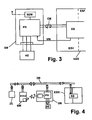
- FIG. 4 an embodiment is sketched in which such a data bus CM is set up between the programmable controller PR of the control module SM and the programmable unit ES of the brake control device EBS.
- operating state signals for example sensor signals of the sensor arrangement SA connected to the brake control device or signals derived therefrom, can be transmitted from the brake control device to the control module via the data bus CM.
- a check of, for example, admissibility criteria for specific instruction signals of the user can be carried out in the programmable unit ES of the brake control device similar to that described with reference to FIG.
- Fig. 3 is again schematically indicated the electrical power supply of the control module from the brake control unit with a supply voltage level VW.
- a data bus CM and a signal connection via discrete individual signal lines, as in FIG. 2, can be implemented in combination.
- the actuation of actuators of the actuator unit AE is only via the control module SM directly provided.
- actuators it is also possible for actuators to be connected to the brake control device in a controllable manner.
- a data bus connection CM is provided between the brake control device EBS and the control module SM of the further control device
- a data bus DB is provided, to which besides the brake control device EBS and the control module SM also devices ZE in the towing vehicle and The operating module BM can also be connected via an interface located there.
- a communication between the operating module BM and the control module SM can take place both via the data bus DB and via the radio signal connection FV, wherein a distinction according to the type of signals to be exchanged can be made, for example by signals from the control module SM to trigger displays in the operating module BM unrestricted data bus DB and / or radio signal connection FV are transferable, whereas instruction signals for triggering actuator functions in the trailer are partially possible only via the data bus DB, so that such instructions can be given only during the presence of the driver in the towing vehicle, not inadvertently when the operating module BM is taken outside the vehicle.
- a preferred embodiment of an operating module BM is sketched by its simplicity.
- This contains a plurality of input elements X1, X2, X3 as in the example of FIG. 2.
- These input elements are designed as pushbutton switching elements, in particular as mechanical pushbuttons, but also as touch input fields or membrane pushbuttons.
- a signal transmission takes place between the operating module and control module via the radio link FV advantageously via a multi-channel radio link, each channel one of the command elements X1, X2 and X3 commandable trailer functions assigned.
- the execution of the input elements as a pure probe is particularly simple and inexpensive and especially for the detached from the vehicle storage of the operating module in clothing bags or the like of particular advantage.
- switchable functions such as the described functions of forcibly lifting or lowering a lift axle, lowering and raising a chassis, applying or releasing a paver brake
- only one probe element is provided for each function, and the effect triggered by actuation of the probe element to a function can be determined via the programming of the further control device.
- the operating module also contains for each commandable function display elements, which are preferably designed as light-emitting diodes.
- each commandable function display elements which are preferably designed as light-emitting diodes.
- two display elements are provided for each function, which are made distinguishable for example by different shape, color or arrangement for the user. Particularly advantageous is the combination of several such differentiation criteria.
- the display elements for the various functions are spatially assigned to the respective input elements.
- three input elements X1, X2, X3 are arranged in a row and associated display elements are arranged in pairs transverse to the row direction of the input elements in direct proximity thereto.
- the input element X1 is assigned two display elements AZ11, AZ12 and arranged directly above the display element X1.
- display elements AZ21, AZ22 are to the input element X2 and display elements AZ31, AZ32 provided to the display element X3 and arranged.
- the display elements AZ12, AZ22 and AZ32 are formed as triangle symbols with the tip pointing downward, the display symbols AZ11, AZ21 and AZ31 as triangular symbols with the tip pointing upwards.
- the display elements AZ11, AZ21 and AZ31 on a mutually identical, different from the display elements AZ12, AZ22 and AZ32 luminescent color.
- the operating module may include a programmable controller module PRB, which on the one hand recognizes the input signals via the input elements X1, X2, X3 and on the other controls the display element and handles the communication with the control module in the trailer via the radio link FV or optionally a data bus connection.
- PRB programmable controller module
- the associated display elements AZ11, AZ12 indicate the current operating state of the lift axle, for example, at currently raised lift axle, the upper display element AZ11, at lowered lift axle, the lower display element AZ12 lights up.
- the current status of the respective function is advantageously only at the first actuation of the input element via the radio link FV from the control module SM, in which the current state of the signal at the input EP1 of FIG. 3 can be removed, is queried.
- a time-limited repeat interval of, for example, a duration between 3 and 10 seconds following the first actuation of the input element X1 or the presence of the current state signal to the function
- the user can change the displayed status of the assigned function by re-actuating the input element X1 instruct or, if the displayed status of the function of its intended Setting to maintain this by omitting a re-actuation of the input element.
- the display elements can also continuously display the current status of the respective trailer function or of the associated actuator.
- the actuation interval can then be advantageously highlighted by an additional signal, for example flashing display or an accompanying acoustic signal.
- the described preferred embodiment of an operating module is characterized by a particularly simple and inexpensive construction, which is also favorable in terms of consequential costs by replacing lost or damaged control modules.
- operating module and associated trailer-side control module in a conventional manner can be individually matched and the communication between paired control module and control module be coded individually.
- a vote of a control module to a specific control module for example, by exchanging individual data on a special connection on the trailer side.
Landscapes
- Engineering & Computer Science (AREA)
- Transportation (AREA)
- Mechanical Engineering (AREA)
- Regulating Braking Force (AREA)
- Braking Systems And Boosters (AREA)
Abstract
Description
Die Erfindung betrifft eine Fahrzeuganhängeranordnung mit einer Bremssteuereinrichtung sowie eine weitere Steuereinrichtung für eine solche Fahrzeuganhängeranordnung.The invention relates to a vehicle trailer assembly with a brake control device and a further control device for such a vehicle trailer assembly.
Fahrzeuganhänger für größere Lasten wie beispielsweise Sattelauflieger weisen ein eigenes, vom Zugfahrzeug aus betätigbares Bremssystem aus. Gebräuchlich ist insbesondere eine pneumatische Betätigung der Bremsen, wofür die Druckluft typischerweise im Zugfahrzeug erzeugt und über Druckluftkupplungen in ein Druckluftsystem des Anhängers eingespeist wird.Vehicle trailers for larger loads such as semi-trailers have their own, from the towing vehicle operable braking system. In particular, a pneumatic actuation of the brakes, for which the compressed air is typically generated in the towing vehicle and fed via compressed air couplings in a compressed air system of the trailer is in common use.
Moderne Bremssysteme in solchen Fahrzeuganhängeranordnungen enthalten eine anhängerseitige Bremssteuereinrichtung, beispielsweise eine unter der Bezeichnung Trailer EBS von den Firmen Knorr Bremse Haldex oder Wabco hergestellte Bremssteuereinrichtung, welche mit einer anhängerseitigen Sensoranordnung verbunden ist und von dieser Sensorsignale betreffend beispielsweise die aktuelle Drehgeschwindigkeit einzelner Räder aufnimmt und daraus Steuersignale für das Bremssystem, insbesondere in kritischen Fahrsituationen ableitet. Die Sensoranordnung kann ferner beispielsweise Sensoren zur Erfassung der Neigung des Fahrzeugs oder des Beladungszustands enthalten. In die Bremssteuereinrichtung können Zusatzfunktionen, wie beispielsweise eine beladungsabhängige und/oder geschwindigkeitsabhängige Steuerung einer Achsliftvorrichtung bei einem mehrachsigem Sattelauflieger integriert sein. Über Eingabeeinrichtungen können von der automatischen Achsliftsteuerung abweichende Kommandos an die Bremssteuereinrichtung gegeben werden, wobei ein Anheben der Liftachse nur unter eingeschränkten Bedingungen von Beladung und Geschwindigkeit möglich ist. Die Bremssteuereinrichtung enthält eine elektronische Einheit, welche zur Abgabe von elektrischen Signalen an mehreren Ausgängen programmierbar und über elektrische Eingänge ansteuerbar sein kann, wodurch in begrenztem Umfang eine Anpassung von Funktionen an spezifische Benutzeranforderungen möglich ist. Eine Veränderung der voreingestellten sicherheitsrelevanten Bremssteuerfunktionen ist über die elektrischen Eingänge oder die Programmierung nicht möglich. Die Bremssteuereinrichtung ist über eine eigenständige elektrische Versorgungsleitung und eine Datenbusleitung mit dem Zugfahrzeug verbunden. Die Bremssteuereinrichtung ist über einen anhängerseitigen Vorratsbehälter vom Zugfahrzeug mit Druckluft versorgt und steuert über Druckluftausgänge die Anhängerbremsen. Die Firma Wabco bietet zusätzlich eine Trailer-Control-Electronic als Ergänzungsgerät an.Modern brake systems in such vehicle trailer assemblies include a trailer-side brake control device, for example a brake controller manufactured under the name Trailer EBS by the companies Knorr brake Haldex or Wabco, which is connected to a trailer-side sensor assembly and receives from this sensor signals concerning, for example, the current rotational speed of individual wheels and control signals for the brake system, especially in critical driving situations derived. The sensor assembly may further include, for example, sensors for detecting the inclination of the vehicle or the loading condition. In the brake control device additional functions, such as a load-dependent and / or speed-dependent control of an axle lift device can be integrated in a multi-axle semitrailer. About input devices can be given by the automatic Achsliftsteuerung deviating commands to the brake control device, with lifting of the lift axle is possible only under limited conditions of loading and speed. The brake control device includes an electronic unit which may be programmable to provide electrical signals at multiple outputs and controllable via electrical inputs, thereby allowing limited adaptation of functions to specific user requirements. It is not possible to change the preset safety-relevant brake control functions via the electrical inputs or the programming. The brake control device is connected to the towing vehicle via a separate electrical supply line and a data bus line. The brake control device is supplied via a trailer-side reservoir from the towing vehicle with compressed air and controls the trailer brakes via compressed air outputs. The Wabco company also offers Trailer Control Electronic as a supplementary device.
Der Erfindung liegt die Aufgabe zugrunde, den Gebrauch einer Fahrzeuganhängeranordnung mit einer Bremssteuereinrichtung für den Benutzer weiter zu verbessern und eine vorteilhafte weitere Steuereinrichtung hierfür anzugeben.The invention has for its object to further improve the use of a vehicle trailer assembly with a brake control device for the user and to provide an advantageous further control device therefor.
Die Erfindung ist im Patentanspruch 1 beschrieben. Die abhängigen Ansprüche enthalten vorteilhafte Ausgestaltungen und Weiterbildungen der Erfindung.The invention is described in
Die Verbindung der weiteren Steuereinrichtung über wenigstens einen Signalpfad mit der Bremssteuereinrichtung ermöglicht vorteilhafterweise die Verknüpfung einer über die Eingabeeinrichtungen der weiteren Steuereinrichtung eingebbaren Anweisung mit in der Bremssteuereinrichtung für die Bremssteuerung vorhandenen Informationen, beispielsweise aus den Sensorsignalen der Sensoranordnung abgeleiteten Informationen oder Informationen über pneumatischer Bremsausgangsanschlüsse der Bremssteuereinrichtung. Hierdurch können insbesondere vom Benutzer steuerbare Aktionen des Anhängers automatisch mit vorgebbaren Sicherheitskriterien verknüpft werden, wodurch solche Aktionen zum einen sicherer und zum anderen für den Benutzer in der Handhabung einfacher werden. Solche vom Benutzer steuerbare Aktionen können beispielsweise bei einem Kipper-Anhänger das Einlegen einer sogenannten Fertigerbremse das Absenken des Chassis sein.The connection of the further control device via at least one signal path with the brake control device advantageously enables the combination of an instruction that can be input via the input devices of the further control device with information present in the brake control device for the brake control, for example information derived from the sensor signals of the sensor device or information about pneumatic brake output ports of the brake control device , As a result, in particular, user-controllable actions of the trailer can be automatically linked to predefinable security criteria, whereby such Actions are safer and easier for the user to handle. Such user-controllable actions can be, for example, in a tipper trailer inserting a so-called paver brake lowering the chassis.
Insbesondere kann über die weitere Steuereinrichtung vorteilhafterweise wenigstens eine über die Bremssteuereinrichtung in Alleinstellung nicht betätigbare Aktuatoreinrichtung ansteuerbar sein. Die weitere Steuereinrichtung kann auch Steuerungsfunktionen von der Bremssteuereinrichtung übernehmen, beispielsweise die Ansteuerung der Achsliftvorrichtung. Hierdurch können Eingriffe auch in einen benutzerkonfigurierbaren Teil der Bremssteuereinrichtung gering gehalten werden. Für die Bremssteuereinrichtungen können dadurch vorteilhafterweise auch kostengünstige einfach aufgebaute Bremssteuereinrichtungen und/oder Bremssteuereinrichtungen unterschiedlicher Hersteller eingesetzt werden.In particular, at least one actuator device, which can not be actuated in isolation via the brake control device, can advantageously be actuated via the further control device. The further control device can also take over control functions from the brake control device, for example the control of the axle lift device. As a result, interventions in a user-configurable part of the brake control device can be kept low. For the brake control devices thereby advantageously also inexpensive simply constructed brake control devices and / or brake control devices from different manufacturers can be used.
Die weitere Steuereinrichtung mit durch den Benutzer vom Zugfahrzeug aus bedienbaren Eingabeeinrichtungen in Verbindung mit einer durch die weitere Steuereinrichtung ansteuerbaren Aktuatoreinrichtung, welche von der Bremssteuereinrichtung nicht betätigbar ist, ermöglicht auf vorteilhafte und einfache Weise eine Erweiterung der Steuerbarkeit von Anhängerfunktionen vom Zugfahrzeug aus, ohne in die wegen der Steuerung des Anhänger-Bremssystems besonders sicherheitsrelevante Bremssteuereinrichtung einzugreifen. Insbesondere kann über die Eingabeeinrichtung, vorzugsweise Tasten, Schalter, Felder einer Bildschirmdarstellung und dergleichen, ein Anweisungssignal zur Ansteuerung wenigstens eines Aktuators der Aktuatoreinrichtung eingegeben werden.The further control device with operable by the user from the towing vehicle input devices in conjunction with a controllable by the further control device actuator, which is not actuated by the brake control device, allows advantageously and easily an extension of the controllability of trailer functions from the towing vehicle, without in the to intervene because of the control of the trailer braking system particularly safety-related brake control device. In particular, an instruction signal for driving at least one actuator of the actuator device can be input via the input device, preferably keys, switches, fields of a screen display and the like.
Die Ansteuerung eines Aktuators der Aktuatoreinrichtung kann in einer ersten vorzugsweise vorteilhaften Ausführung durch direkte Verdrahtung zwischen der weiteren Steuereinrichtung und dem Aktuator, beispielsweise einem elektrisch schaltbaren Fluidventil, einem Motor, einem Relais usw. erfolgen. In anderer Ausführung kann eine mehrere Aktuatoren mit der weiteren Steuereinrichtung verbindende Busleitung zur Signalübertragung vorgesehen sein, wofür die einzelnen Aktuatoren dann mit Adress- und Datendekodierern ausgestattet und individuell mit Steuersignalen adressierbar sind. Für eine solche Verbindung über eine Busleitung kann auch ein gegebenenfalls bereits vorhandenes Datenbussystem im Anhänger bzw. zwischen Zugfahrzeug und Anhänger mit benutzt sein. eine Verknüpfung eines Anweisungssignals nach Maßgabe einer Eingabe eines Benutzers mit einem Betriebszustandssignal erfolgt dabei vorteilhafterweise in der weiteren Steuereinrichtung.The activation of an actuator of the actuator device can be effected in a first, preferably advantageous embodiment by direct wiring between the further control device and the actuator, for example an electrically switchable fluid valve, a motor, a relay, etc. In another embodiment, a plurality of actuators with the further control device connecting bus line can be provided for signal transmission, for which the individual actuators are then equipped with address and data decoders and individually addressed with control signals. For such a connection via a bus line, an optionally existing data bus system can also be used in the trailer or between towing vehicle and trailer. a linkage of an instruction signal in accordance with an input of a user with an operating state signal is advantageously carried out in the further control device.
In anderer vorteilhafter Ausführung kann ein Anweisungssignal nach Maßgabe der Eingabe eines Benutzers über den Signalpfad an die Bremssteuereinrichtung geleitet werden, welche ihrerseits, gegebenenfalls nach einer vorgebbaren Verknüpfung mit einem Betriebszustandssignal, einen Aktuator betätigt. Vorteilhafterweise erfolgt eine Rückmeldung über die Betätigung eines Aktuators von der Bremssteuereinrichtung an die weitere Steuereinrichtung.In another advantageous embodiment, an instruction signal in accordance with the input of a user via the signal path to the brake control device are passed, which in turn, optionally after a predetermined linkage with an operating condition signal, actuates an actuator. Advantageously, a feedback on the actuation of an actuator from the brake control device to the further control device.
Die weitere Steuereinrichtung ist vorteilhafterweise elektronisch programmierbar, so dass für verschiedene Fahrzeuganhängeranordnungen, für verschiedene Zugfahrzeug-Anhänger-Kombinationen oder für unterschiedliche Einsatzzwecke Möglichkeiten und Beschränkungen der Eingabe bzw. Ansteuerung der Aktuatoreinrichtung an den jeweiligen Einzelfall besonders gut angepasst werden kann.The further control device is advantageously electronically programmable, so that for various vehicle trailer arrangements, for different tractor-trailer combinations or for different purposes, possibilities and limitations of the input or control of the actuator to the respective individual case can be particularly well adjusted.
Die weitere Steuereinrichtung kann in bevorzugter Ausführung ein anhängerseitiges angeordnetes Steuermodul und ein zugfahrzeugseitig anordenbares Bedienmodul enthalten. Bedienmodul sind zur Signalübertragung zumindest von dem Bedienmodul zu dem Steuermodul, vorzugsweise auch in Gegenrichtung eingerichtet. Die Signalübertragung kann auf an sich bekannte Weise erfolgen, insbesondere über eine mehradrige direkte Steuerleitung, über ein Bussystem, an welches auch andere Teilnehmer, insbesondere auch die elektronische Bremssteuereinrichtung angeschlossen sein können. Als ein solches Bussystem kann insbesondere auch ein zwischen Zugfahrzeug und Anhänger bestehendes Bussystem für die Signalübertragung mit ausgenutzt werden. In bevorzugter Ausführung ist zur Signalübertragung zwischen Bedienmodul und Steuermodul eine drahtlose Verbindung, vorzugsweise eine Funkverbindung vorgesehen. Letztere ermöglicht vorteilhafterweise die Handhabung des Bedienmoduls auch außerhalb des Zugfahrzeugs, beispielsweise während Belade- oder Entlade-Vorgängen. Leitungsgebundene Signalübertragung zwischen dem Bedienmodul und dem Steuermodul und drahtlose Signalübertragung können auch gemeinsam realisiert sein, wobei beide Übertragungsarten dieselben Signale umfassen können. In anderer vorteilhafter Ausführung kann vorgesehen sein, dass eine Übertragungsart für bestimmte Signale gesperrt ist, so dass z. B. über eine Funkverbindung keine Signale übertragbar sind, welche Anweisungen entsprechen, welche die Anwesenheit des Benutzers in der Fahrerposition erfordern, beispielsweise das Lösen einer angelegten Fertigerbremse.In a preferred embodiment, the further control device may include a trailer-side arranged control module and a control module that can be arranged on the towing vehicle side. Control module are set up for signal transmission at least from the operating module to the control module, preferably also in the opposite direction. The signal transmission can take place in a manner known per se, in particular via a multi-wire direct control line, via a bus system to which other subscribers, in particular also the electronic brake control device, can be connected. As such a bus system, in particular, a bus system existing between towing vehicle and trailer can also be utilized for the signal transmission. In a preferred embodiment, a wireless connection, preferably a radio link, is provided for signal transmission between the operating module and the control module. The latter advantageously makes it possible to handle the operating module outside the towing vehicle, for example during loading or unloading operations. Wired signal transmission between the control module and the control module and wireless signal transmission can also be implemented together, both types of transmission can include the same signals. In another advantageous embodiment, it may be provided that a transmission for certain signals is disabled, so that z. B. via a radio link signals are not transferable, which correspond to instructions that require the presence of the user in the driver's position, such as the release of an applied paver brake.
Bedienmodul und Steuermodul können paarweise individuell einander zugeordnet sein, so dass jedem Steuermodul bzw. dem mit diesem verbundenen Anhänger genau ein bestimmtes Bedienmodul zugeordnet ist und Fremd-Steuereinwirkungen, z. B. bei Funkverbindungen ausgeschlossen werden können. In anderer Ausführung, insbesondere für leitungsgebende Signalübertragung können die Bedienmodule ohne individuelle Zuordnung auf Anhängertypen abgestimmt oder in wieder anderer Ausführung für mehrere Anhängertypen übergreifend verwendbar eingerichtet sein. Einheitlich ausgeführte Bedienmodule können durch Austausch spezifischer individueller Kennungen mit dem Steuermodul eines Anhängers auf den Signalzustand mit diesem Steuermodul eingerichtet werden. Übertragungsarten und gegebenenfalls Protokolle für die leitungsgebundene oder drahtlose Signalübertragung sind dem Fachmann bekannt.The control module and the control module can be individually assigned to one another in pairs, so that exactly one specific control module is assigned to each control module or to the trailer connected to it, and third-party control actions, e.g. B. can be excluded in radio communications. In another embodiment, in particular for conductive signal transmission If necessary, the operating modules can be adapted to trailer types without individual assignment or can be set up to be used in a different way for several trailer types. Uniform operating modules can be set up by exchanging specific individual identifiers with the control module of a trailer for the signal state with this control module. Types of transmission and optionally protocols for wireline or wireless signal transmission are known to those skilled in the art.
Bei einer Aufteilung der Steuereinrichtung in ein zugfahrzeugseitig anordenbares Bedienmodul und ein am Anhänger angeordnetes Steuermodul kann das Bedienmodul und/oder vorzugsweise das Steuermodul elektronisch programmierbar sein. Das anhängerseitige Steuermodul bezieht seine Betriebsspannung vorzugsweise von der Bremssteuereinrichtung, insbesondere über einen der programmierbaren elektrischen Ausgänge der Bremssteuereinrichtung.When the control device is divided into an operating module which can be arranged on the towing vehicle side and a control module arranged on the trailer, the operating module and / or preferably the control module can be electronically programmable. The trailer-side control module preferably draws its operating voltage from the brake control device, in particular via one of the programmable electrical outputs of the brake control device.
Beispielsweise kann vom Benutzer eine Anweisung in die weitere Steuereinrichtung eingegeben werden, die von der Bremssteuereinrichtung nach Maßgabe der Geschwindigkeit und/oder des Beladungszustands entgegen der automatischen Einstellung zwangsweise anzuheben, z. B. zur Traktionsverbesserung des Zugfahrzeugs, oder zwangsweise abzusenken. Die Bremssteuereinrichtung nimmt über den Signalpfad ein entsprechendes Steuersignal von der weiteren Steuereinrichtung auf und wirkt auf die Achsliftvorrichtung ein, wobei aber in der Bremssteuereinrichtung Sicherheitskriterien vorgegeben sind, welche gegenüber dem Steuersignal von der weiteren Steuereinrichtung vorrangig sind und die Ausführung der Anweisung unterbinden oder begrenzen können, beispielsweise auf eine kurze Zeitdauer und/oder auf einen Geschwindigkeitsbereich oberhalb oder unterhalb einer Geschwindigkeitsschwelle. In anderer Ausführung kann die weitere Steuereinrichtung eine Geschwindigkeitsinformation von der Bremssteuereinrichtung empfangen und die Ansteuerung der Achsliftvorrichtung und/oder die Entscheidung über die Zulässigkeit einer Anhebung selbst übernehmen.For example, the user may enter an instruction into the further control device to forcibly lift the brake control device against the automatic adjustment in accordance with the speed and / or the load state, e.g. B. to improve the traction of the towing vehicle, or forcibly lower. The brake control device receives via the signal path a corresponding control signal from the further control device and acts on the Achsliftvorrichtung, but in the brake control device safety criteria are given, which are prior to the control signal from the other control device and can prevent or limit the execution of the instruction, for example, for a short period of time and / or for a speed range above or below a speed threshold. In another embodiment, the further control device, a speed information received by the brake control device and take over the control of the Achsliftvorrichtung and / or the decision on the permissibility of an increase itself.
In anderem Anwendungsbeispiel kann vom Benutzer über die weitere Steuereinrichtung eine Bremsfunktion mit mäßiger Bremskraft aktiviert werden, welche z. B. als sogenannte Fertigerbremse beim Entladebetrieb eines Kippers an einem Straßenfertiger vorteilhaft ist. Dabei wird der Kipper-Anhänger gegebenenfalls samt Zugfahrzeug von dem Straßenfertiger in dessen Fertigungsrichtung geschoben, während nach und nach Belagmaterial aus dem Kipper dem Straßenfertiger zugeführt wird. Um auch bei leicht abschüssiger Fahrbahn zu vermeiden, dass sich Kipper und Zugfahrzeug vom Straßenfertiger entfernen, kann über die Steueranweisung der Fertigerbremsfunktion ein definierter Bremsdruck eingestellt werden, so dass ein Schieben des Anhängers samt Zugfahrzeug durch den Straßenfertiger möglich ist, die Zugfahrzeug-Anhänger-Kombination aber nicht vom Fertiger wegrollt. Durch Verknüpfen mit einer Geschwindigkeitsinformation der Bremseinrichtung kann die Ausführung dieser Fertigerbremsanweisung auf einen für den Vorschub von Straßenfertigern typischen Geschwindigkeitsbereich beschränkt werden. Vorteilhafte Ausführungen zu einer solchen Fertigerbremsfunktion sind noch im Detail beschrieben.In another application example, a braking function with moderate braking force can be activated by the user via the further control device, which z. B. as a so-called paver brake during unloading a dumper on a paver is advantageous. In this case, the tipper trailer is possibly pushed together with towing vehicle by the paver in the production direction, while gradually covering material from the tipper is supplied to the paver. In order to avoid even on slightly sloping road that tipper and towing vehicle from the paver, can be set via the control instruction of the paver brake function a defined brake pressure, so that a sliding of the trailer together with towing vehicle by the paver is possible, the tractor-trailer combination but does not roll away from the paver. By associating with speed information of the braking device, the execution of this paver brake instruction may be limited to a speed range typical of the advancement of pavers. Advantageous embodiments of such a paver brake function are described in detail.
In vorteilhafter Ausführung kann für die Übermittlung von Signalen zwischen Bremssteuereinrichtungen und weiterer Steuereinrichtungen vorgesehen sein, von der Bremssteuereinrichtung, welche mit der Sensoranordnung verbunden ist und von dieser Sensorsignale aufnimmt, wenigstens ein Betriebszustandssignal, welches einen den aktuellen Betriebszustand der Fahrzeuganhängeranordnung beschreibenden Parameter repräsentiert, zu übertragen. Der aktuelle Betriebszustand kann durch eine Mehrzahl von Parametern charakterisiert sein, von welchem aber nicht alle zur Übermittlung an die weitere Steuereinrichtung bedeutsam und vorgesehen sein müssen.In an advantageous embodiment may be provided for the transmission of signals between brake control devices and other control devices, from the brake control device, which is connected to the sensor assembly and receives from this sensor signals, at least one operating state signal representing a current operating state of the vehicle trailer assembly parameter to transmit , The current operating state can be characterized by a plurality of parameters but not all of which must be significant and provided for transmission to the further controller.
Ein solcher Parameter kann die aktuelle Geschwindigkeit des Anhängers sein, welche aus dem typischerweise mehreren Radsensoren ableitbar ist. Als Betriebszustandssignal kann ein jeweils aktueller digitalisierter Geschwindigkeitswert an die weitere Steuereinrichtung übertragen werden oder auch in vereinfachter Form nur ein zweiwertiges Signal, welches als Schwellwertsignal die Überschreitung oder Unterschreitung eines bestimmten Geschwindigkeitsschwellwerts angibt. Im letztgenannten Fall können für verschiedene Schwellwerte getrennte Signale vorgesehen sein.Such a parameter may be the current speed of the trailer, which is derivable from the typically several wheel sensors. As an operating state signal, a respective current digitized speed value can be transmitted to the further control device or even in a simplified form only a bivalent signal which indicates the exceeding or falling below a certain speed threshold value as a threshold signal. In the latter case separate signals can be provided for different threshold values.
Ein anderer Parameter kann die Neigung des Fahrzeugs sein, welche einerseits in der Bremssteuereinrichtung für ein Antiblockiersystem und ein elektronisches Stabilitätsprogramm wesentlich sein können, welche andererseits bei einem Kipper-Anhänger für die über die weitere Steuereinrichtung auslösbare Anhebung der Kippmulde von Bedeutung sein kann, insbesondere als Schwellwertsignal für die Fahrzeugneigung dahingehend, ob ein Kippvorgang eingeleitet werden darf, oder als Zeitverlauf eines Neigungswerts, ob sich die Fahrzeugneigung beim Einleiten eines Kippvorgangs in sicherheitsrelevantem Maß verändert und die Kippmulde eventuell entgegen der Benutzereingabe wieder abgesenkt werden muss.Another parameter may be the inclination of the vehicle, which may be essential on the one hand in the brake control device for an anti-lock brake system and an electronic stability program, which on the other hand may be of importance for a tipper trailer for raising the dump body via the further control device, in particular as Threshold signal for the vehicle inclination as to whether a tipping process may be initiated, or as a time course of a slope value, whether the vehicle inclination changes when initiating a tipping operation in safety-relevant measure and the dump body may need to be lowered again against the user input.
Ein Betriebszustandssignal kann insbesondere auch ein Betätigungssignal für einen von der Bremssteuereinrichtung ansteuerbaren Aktuator sein. Beispielsweise kann bei einem durch die Bremssteuereinrichtung elektrisch ansteuerbaren Aktuator das Ansteuersignal abgegriffen und einem Eingang der weiteren Steuereinrichtung parallel zugeführt sein.An operating state signal can in particular also be an actuation signal for an activatable by the brake control device actuator. For example, in the case of an actuator which can be controlled electrically by the brake control device, the drive signal can be tapped off and supplied in parallel to an input of the further control device.
Die Übertragung eines Betriebszustandssignals von der Bremssteuereinrichtung an die weitere Steuereinrichtung ermöglicht zum einen die Anzeige relevanter Betriebszustände für den Benutzer und zum anderen die Verknüpfung der Betriebszustandssignale mit Benutzereingaben zw. die Sperrung oder Freigabe von Benutzereingaben nach Maßgabe der Betriebszustandssignale.The transmission of an operating state signal from the brake control device to the further control device on the one hand enables the display of relevant operating states for the user and on the other hand, the linking of the operating state signals with user inputs zw. The blocking or release of user input in accordance with the operating state signals.
Der Signalpfad zwischen Bremssteuereinrichtung und weiterer Steuereinrichtung in eine oder beide Signalrichtungen kann direkte Verbindungen zwischen entsprechend eingerichteten Signal-Eingängen und Signal-Ausgängen der Bremssteuereinrichtung und der weiteren Steuereinrichtungen umfassen, wobei die Signal-Eingänge und Signal-Ausgänge vorzugsweise durch Programmierung der jeweiligen Einrichtungen den Signalarten und Funktionen zugewiesen sind. Der Signalpfad kann eine für verschiedene Signale gemeinsame Datenleitung zwischen Bremssteuereinrichtung und weiterer Steuereinrichtung umfassen. Der Signalpfad kann schließlich auch eine Datenbusleitung umfassen, an welche sowohl die Bremssteuereinrichtung als auch die weitere Steuereinrichtung sowie weitere Teilnehmer angeschlossen sind. Eine solche Datenbusleitung kann insbesondere auch zur Signalübertragung zwischen einem zugfahrzeugseitigen Bedienmodul und einem anhängerseitigen Steuermodul dienen. Eine Datenbusleitung zwischen der Bremssteuereinrichtung und der weiteren Steuereinrichtung ist vorteilhafterweise getrennt von der zur Übertragung von Bremssignalen zwischen Zugfahrzeug und Bremssteuereinrichtung vorhandenen Datenbusleitung. Die weitere Steuereinrichtung kann aber als reiner Datenempfänger ohne Sendestufe auch an einer solchen Datenbusleitung angeschlossen sein und auf diesem Weg Betriebszustandssignale von der Bremssteuereinrichtung empfangen.The signal path between the brake control device and further control device in one or both signal directions may include direct connections between appropriately configured signal inputs and signal outputs of the brake control device and the further control devices, wherein the signal inputs and signal outputs preferably by programming the respective devices the signal types and functions are assigned. The signal path may include a common data line for different signals between the brake control device and another control device. Finally, the signal path can also include a data bus line, to which both the brake control device and the further control device as well as other subscribers are connected. Such a data bus line can in particular also serve for signal transmission between a towing vehicle-side operating module and a trailer-side control module. A data bus line between the brake control device and the further control device is advantageously separate from the data bus line present for transmitting brake signals between towing vehicle and brake control device. The further control device can, however, also be connected to such a data bus line as a pure data receiver without a transmission stage and receive operating state signals from the brake control device in this way.
Vorteilhafterweise kann die Aktuatoranordnung wenigstens einen von der weiteren Steuereinrichtung elektrisch ansteuerbaren Aktuator enthalten, welcher von der Bremssteuereinrichtung nicht ansteuerbar ist. Der Umfang der ansteuerbaren Aktuatoren ist dadurch auf vorteilhafter Weise erweiterbar, wobei durch die Übernahme von Signalen, insbesondere Betriebszustandssignalen von der Bremssteuereinrichtung in die weitere Steuereinrichtung über den wenigstens einen Signalpfad auf einfache Weise in der weiteren Steuereinrichtung Kriterien, z. B. Sicherheitskriterien, vorgegeben und überwacht werden können.Advantageously, the actuator assembly may include at least one actuator controllable by the further control device, which actuator can not be controlled by the brake control device. The scope of the controllable actuators can be extended in an advantageous manner, with the acquisition of signals, in particular operating state signals from the brake control device in the further control device via the at least one signal path in a simple manner in the further control device criteria, eg. B. safety criteria, can be specified and monitored.
Eine drahtlose Funk-Signalübertragung zwischen Steuermodul und Bedienmodul erfolgt vorteilhafterweise in zur privaten Nutzung freien Frequenzbändern. Vorzugsweise erfolgt die Funk-Signalübertragung für die Steuerung mehrerer verschiedener Anhängerfunktionen über eine mehrkanalige Funkverbindung. Sende- und Empfangsmodule sind für solche Übertragungsarten mit funktechnischer Zulassung kostengünstig verfügbar.A wireless radio signal transmission between the control module and the operating module is advantageously carried out in private frequency bands free. Preferably, the radio signal transmission for the control of several different trailer functions via a multi-channel radio connection. Transmit and receive modules are available inexpensively for such types of transmission with radio approval.
Das Bedienmodul enthält in vorteilhafter Ausführung wenigstens ein Eingabeelement zur Ansteuerung wenigstens eines Aktuators der anhängerseitigen Aktuatoranordnung über das Steuermodul und eventuell die Bremssteuereinrichtung sowie wenigstens ein Ausgabeelement zur Ausgabe eines Statussignals zu einem Aktuator. Das Eingabeelement ist vorteilhafterweise ein monostabiler Tastschalter, welcher nach Betätigung selbsttätig in eine Ruhestellung zurückkehrt, vorzugsweise ein mechanischer Ein-Taster mit Federrückstellung. Für eine entsprechende Funktionsweise sind auch elektronische Berührungsschalter oder Folienschalter bekannt. Prinzipiell ist auch eine Spracheingabe anwendbar. Das Ausgabeelement kann vorteilhafterweise eine optische Anzeige und/oder eine akustische Anzeige umfassen. Bauelemente und Peripherieschaltungen für derartige Eingabeelemente und Ausgabeelemente sind bekannt und vielfältig verfügbar. Das Statussignal gibt dem aktuellen Status eines Aktuators mit durch dem Benutzer veränderbaren Status an, beispielsweise Liftachse angehoben oder abgesenkt.The adjustment module contains in an advantageous embodiment at least one input element for controlling at least one actuator of the trailer-side actuator assembly via the control module and possibly the brake control device and at least one output element for outputting a status signal to an actuator. The input element is advantageously a monostable pushbutton, which automatically returns to a rest position after actuation, preferably a mechanical on-button with spring return. For a corresponding operation and electronic touch switches or membrane switches are known. In principle, a voice input is applicable. The output element may advantageously comprise a visual display and / or an acoustic display. Components and peripheral circuits for such input elements and output elements are known and widely available. The status signal indicates the current status of an actuator with user-changeable status, for example lifted or lowered lift axle.
Unterschiedliche Ausgabe-Informationen können optisch durch unterschiedliche Farben, unterschiedliche Formen oder Symbole und/oder unterschiedliche Anzeigepositionen und/oder Blinken angezeigt werden. Optische Anzeigeelemente sind in bevorzugter Ausführungsform Leuchtdioden.Different output information may be visually displayed by different colors, different shapes or symbols, and / or different display positions and / or flashing. Optical display elements are in a preferred embodiment LEDs.
Eine akustische Ausgabe unterschiedlicher Informationen kann z. B. durch unterschiedliche Tonhöhen und/oder unterschiedliche Tonfolgen erfolgen.An acoustic output of different information may, for. B. by different pitches and / or different tone sequences.
Neben Statussignalen können auch weitere Informationssignale ausgebbar sein, beispielsweise Betätigungssignale für ausgeführte Anweisungen, Ablehnungssignale für unzulässige Anweisungen usw.In addition to status signals, further information signals can also be output, for example actuation signals for executed instructions, rejection signals for impermissible instructions, etc.
In vorteilhafter Ausführung enthält die weitere Steuereinrichtung als Eingabeelement zur Betätigung eines zwischen zwei inständigen umschaltbar betätigbaren Aktuators, z. B. einer Achsliftvorrichtung lediglich einen Taster, über welchen ein Anweisungssignal zum Wechsel des Aktuatorzustands eingebbar ist. Vorteilhafterweise erfolgt eine Ansteuerung zur Umschaltung des Aktuatorzustands erst nach zweifacher Betätigung des Tasters, wobei nach einer ersten Betätigung, z. B. zur Absenkung der Liftachse, dem Benutzer der aktuelle Zustand des Aktuators ausgegeben wird, und der Benutzer innerhalb eines zeitlich begrenzten Intervalls durch erneutes Betätigen des Tasters die Umschaltung bestätigen kann, oder, wenn der aktuelle Zustand bereits dem angestrebten Zustand entspricht, durch Unterlassen einer zweiten Tasterbetätigung innerhalb des zeitbegrenzten Intervalls die Aktion abbricht. Das Intervall kann beispielsweise 3 bis 10 Sekunden umfassen. Während des Intervalls wird vorteilhafterweise ein besonderes Signal, z. B. ein Blinken einer optischen Anzeige oder ein definierter, gegebenenfalls unterbrochener Signalton ausgegeben.In an advantageous embodiment, the further control device contains as an input element for actuating an operable between two permanently switchable actuator, for. As an Achsliftvorrichtung only a button, via which an instruction signal for changing the actuator state is entered. Advantageously, a control for switching the actuator state takes place only after two actuation of the button, wherein after a first operation, for. B. for lowering the lift axle, the user of the current state of the actuator is output, and the user within a time-limited interval by pressing the button again can confirm the switching, or if the current state already corresponds to the desired state, by omitting a second button operation within the time-limited interval, the action stops. For example, the interval may be 3 to 10 seconds. During the interval advantageously a special signal, z. B. a flashing of an optical display or a defined, possibly interrupted beep is issued.
In anderer vorteilhafter Ausführung können für unterschiedliche Anweisungen unterschiedliche Betätigungen von Eingabeelementen, z. B. Betätigen eines Doppeltasters in eine von zwei entgegen gesetzten Richtungen für Anheben oder Absenken einer Liftachse, oder je ein separates Eingabeelement für jede verschiedene Anweisung, also z. B. ein erster Taster zum Anheben und ein zweiter Taster zum Absenken.In another advantageous embodiment, different actuations of input elements, for. B. actuating a double button in one of two opposite directions for raising or lowering a lift axle, or depending on a separate input element for each different instruction, so z. B. a first button for lifting and a second button for lowering.
Die Erfindung ist nachfolgend anhand bevorzugter Ausführungsbeispiele unter Bezugnahme auf die Abbildungen noch eingehend veranschaulicht. Dabei zeigt:
- Fig. 1
- einen prinzipiellen Aufbau einer Bremssteuereinrichtung,
- Fig. 2
- eine erste bevorzugte Ausführung einer Signalverbindung zwischen Bremssteuereinrichtung und weiterer Steuereinrichtung,
- Fig. 3
- eine alternative Ausführung einer Signalverbindung zwischen Bremssteuereinrichtung und weiterer Steuereinrichtung,
- Fig. 4
- eine Ausführungsform mit einem Datenbus als Signalverbindung,
- Fig. 5
- eine vorteilhafte Ausführung eines Bedienmoduls einer weiteren Steuereinrichtung.
- Fig. 1
- a basic structure of a brake control device,
- Fig. 2
- a first preferred embodiment of a signal connection between brake control device and further control device,
- Fig. 3
- an alternative embodiment of a signal connection between the brake control device and another control device,
- Fig. 4
- an embodiment with a data bus as a signal connection,
- Fig. 5
- an advantageous embodiment of an operating module of another control device.
In Fig. 1 ist schematisch eine elektronische Bremssteuereinrichtung in einer Fahrzeuganhängeranordnung mit einigen Peripherieelementen skizziert, wobei die schematische Skizze im wesentlichen auf die für die weiteren Ausführungen benötigten bzw. zweckmäßigen Elemente beschränkt ist. Die realen elektronischen Bremssteuereinrichtungen, wie beispielsweise ein Trailer-EBS der Firmen Knorr, Haldex oder Wabco, sind demgegenüber relativ komplex aufgebaut.In Fig. 1, an electronic brake control device is schematically outlined in a vehicle trailer assembly with some peripheral elements, wherein the schematic diagram substantially to that for the other embodiments required or appropriate elements is limited. The real electronic brake control devices, such as a trailer EBS of the companies Knorr, Haldex or Wabco, on the other hand, are relatively complex.
Die Bremssteuereinrichtung enthält eine elektronische Steuereinheit ES, welche in den wesentlichen sicherheitsrelevanten Teilen vom Hersteller vorprogrammiert und vom Benutzer nicht veränderbar ist. Zusätzlich kann die Steuereinheit ES in nicht sicherheitskritischen Aspekten programmierbar sein, was in einer bevorzugten Ausführungsform der vorliegenden Erfindung ausgenutzt wird.The brake control device contains an electronic control unit ES, which is preprogrammed in the essential safety-relevant parts by the manufacturer and can not be changed by the user. In addition, the control unit ES may be programmable in non-safety-critical aspects, which is exploited in a preferred embodiment of the present invention.
Die Bremssteuereinrichtung EBS ist in der Skizze in einen vom Benutzer nicht beeinflussbaren, von Herstellerseite der Bremssteuereinrichtung EBS festgelegten Teil ESF und einen begrenzt Veränderungen durch den Benutzer zulassenden variablen Teil ESV schematisch unterteilt.The brake control device EBS is diagrammatically subdivided into a part ESF which can not be influenced by the user and is defined by the manufacturer side of the brake control device EBS and a variable part ESV which is limited by the user.
Die Bremssteuereinrichtung ESB ist über eine Stromversorgungsleitung W unabhängig von den übrigen elektrischen Verbrauchern des Anhängers vom Zugfahrzeug aus versorgt, typischerweise mit einer Spannung von 24 Volt. Gleichfalls vom Zugfahrzeug aus erfolgt die Versorgung der Bremssteuereinrichtung EBS mit Druckluft über eine Versorgungsleitung DV und einen anhängerseitigen Vorratsbehälter VB, aus welchem über eine Druckluftleitung DL Druckluft auf einen Versorgungseingang der Bremssteuereinrichtung geführt ist. Die Bremssteuereinrichtung EBS hat Druckluftausgänge zur Bremsanlage BA des Fahrzeugs, in welcher typischerweise eine Betriebsbremsanlage und eine Feststellbremsanlage unterschieden werden. Der Bremsdruck, mit welcher die Betriebsbremsanlage beaufschlagt wird, ist variabel und durch den Fahrer abhängig vom Druck auf das Bremspedal vorgebbar. Hierfür ist eine pneumatische Bremsdruckleitung BD auf einen pneumatischen Eingangsanschluss der Bremssteuereinrichtung EBS geführt, wo ein Drucksensor den Druck einer Bremsanforderung über die Bremsdruckleitung BD erfasst und die Betriebsbremsanlage mit einem entsprechenden Druck beaufschlagt. Zusätzlich kann ein CAN-Datenbus CB vorgesehen sein, welcher beispielsweise bei dem Trailer EBS von Knorr ein zugfahrzeugseitiges EBS mit dem anhängerseitigen EBS verbindet und über welchen gleichfalls ein variables Bremsanforderungssignal übertragbar ist. Dieser CAN-Datenbus CB ist aus Sicherheitsgründen nicht zum Anschluss weiterer Busteilnehmer vorgesehen.The brake control device ESB is supplied via a power supply line W independently of the other electrical consumers of the trailer from the towing vehicle, typically with a voltage of 24 volts. Likewise from the towing vehicle, the supply of the brake control device EBS with compressed air via a supply line DV and a trailer-side reservoir VB, from which via a compressed air line DL compressed air is fed to a supply input of the brake control device. The brake control device EBS has compressed air outputs to the brake system BA of the vehicle, in which typically a service brake system and a parking brake system can be distinguished. The brake pressure, which is applied to the service brake system, is variable and can be specified by the driver depending on the pressure on the brake pedal. This is a pneumatic Brake pressure line BD guided to a pneumatic input port of the brake control device EBS, where a pressure sensor detects the pressure of a brake request via the brake pressure line BD and applied to the service brake system with a corresponding pressure. In addition, a CAN data bus CB can be provided which, for example, connects a towing vehicle-side EBS to the trailer-side EBS in the trailer EBS of Knorr and via which a variable brake request signal can likewise be transmitted. For safety reasons, this CAN data bus CB is not intended for the connection of further bus subscribers.
Die Bremssteuereinrichtung EBS ist darüber hinaus mit einer externen Sensoranordnung SA, welche in Fig. 1 lediglich schematisch dargestellt ist und welche eine Mehrzahl einzelner Sensoren enthält, verbunden. Sensoren der Sensoranordnung SA sind beispielsweise Radumdrehungssensoren, Beschleunigungssensoren und/oder Neigungssensoren, Drucksensoren, Positionssensoren usw., welche für die Steuerung der Bremsanlage, insbesondere der Betriebsbremsanlage zur Fahrstabilisierung von Bedeutung sind. Die Fahrstabilisierung kann insbesondere die an sich bekannten Funktionen eines Antiblockiersystems (ABS), eines elektronischen Stabilisierungsprogramms (ESP) oder eines Rollstabilisierungsprogramms (RSP) umfassen. Die Bremssteuereinrichtung EBS enthält ferner mehrere interne Sensoren, insbesondere Drucksensoren zur Erfassung von pneumatischen Drücken, mit welchen einzelne Komponenten der Bremsanlage beaufschlagt sind.The brake control device EBS is also connected to an external sensor arrangement SA, which is shown only schematically in FIG. 1 and which contains a plurality of individual sensors. Sensors of the sensor arrangement SA are, for example, wheel rotation sensors, acceleration sensors and / or inclination sensors, pressure sensors, position sensors, etc., which are important for controlling the brake system, in particular the service brake system for driving stabilization. The driving stabilization may in particular include the known functions of an anti-lock braking system (ABS), an electronic stabilization program (ESP) or a roll stabilization program (RSP). The brake control device EBS further includes a plurality of internal sensors, in particular pressure sensors for detecting pneumatic pressures, which are applied to individual components of the brake system.
Die Bremssteuereinrichtung EBS enthält in dem veränderbaren und auf individuelle Benutzerbedürfnisse abstimmbaren variablen Teil ESV einen oder mehrere elektrische Eingänge EB sowie einen oder mehrere elektrische Ausgänge AB. Die Ausgänge sind typischerweise binär umschaltbar zwischen Betriebsspannung der Bremssteuereinrichtung (z. B. 24 Volt) und Massepotential (0 Volt). In entsprechender Weise werden im Regelfall die elektrischen Eingänge EB der Bremssteuereinrichtung binär abgefragt in der Weise, ob eine Eingangssignalspannung über oder unter einem Schwellwert oder Schwellwertbereich liegt.The brake control device EBS contains in the variable and tunable to individual user needs variable part ESV one or more electrical inputs EB and one or more electrical outputs AB. The outputs are typically binary switchable between operating voltage of the brake control device (eg 24 volts) and ground potential (0 Volt). In a corresponding manner, as a rule, the electrical inputs EB of the brake control device are queried in binary fashion in such a way as to determine whether an input signal voltage is above or below a threshold value or threshold value range.
Von Bedeutung ist, dass die elektronische Steuereinrichtung es ermöglicht, aus Eingangsdaten der elektrischen Anschlüsse EB und aus im nicht veränderbaren Teil ESF vorliegenden Daten z. B. der externen Sensoranordnung oder der internen Sensoren nach programmierbaren Vorschriften einzelne Ausgänge des Blocks elektrischer Ausgänge AB individuell und, soweit die Eingangsgrößen veränderlich sind, veränderlich zu schalten. Beispielsweise kann die Bremssteuereinrichtung in bekannter Weise aus dem über Drucksensoren erkannten Beladungszustand eine vollautomatische Steuerung einer Achsliftvorrichtung und/oder eine geschwindigkeitsabhängige Rückstellung der Luftfederung bei eventuell im Stand abgesenktem Chassis vornehmen. An einem Ausgang kann ein geschwindigkeitsabhängiges Signal abgegeben werden, welches anzeigt, ob die aktuelle Geschwindigkeit über oder unter einer vorgebbaren Geschwindigkeitsschwelle liegt. Aus den Radumdrehungssensoren kann ferner ein Wegsignal abgeleitet und als Taktsignal an einen externen Kilometerzähler gegeben werden.It is important that the electronic control device makes it possible, from input data of the electrical connections EB and data present in the unchangeable part ESF z. B. the external sensor array or the internal sensors according to programmable rules individual outputs of the block of electrical outputs AB individually and, as far as the input variables are variable, to switch changeable. For example, the brake control device can perform a fully automatic control of an axle lift device and / or a speed-dependent return of the air suspension in the case of a possibly lowered chassis in a known manner from the load state detected via pressure sensors. At an output, a speed-dependent signal can be output, which indicates whether the current speed is above or below a predefinable speed threshold. From the Radumdrehungssensoren also a path signal can be derived and given as a clock signal to an external odometer.
Zusätzlich kann vorgesehen sein, dass ein weiterer Datenbus z. B. zu der Bremssteuereinrichtung geführt wird, an welchen auch weitere Teilnehmer anschließbar sind.In addition, it can be provided that a further data bus z. B. is guided to the brake control device to which other participants are connected.
Fig. 2 zeigt eine bevorzugte Ausführung einer Anschlussmöglichkeit einer weiteren Steuereinrichtung an eine hier nur noch ausschnittsweise dargestellte Bremssteuereinrichtung EBS.FIG. 2 shows a preferred embodiment of a connection possibility of a further control device to a brake control device EBS, which is shown only in partial detail here.
Die weitere Steuereinrichtung WSE enthalte in bevorzugter Weise ein anhängerseitig fest installiertes Steuermodul SM sowie ein von diesem getrenntes, im Führerhaus des Zugfahrzeugs anordenbares und vorzugsweise von dort entnehmbares und mobil benutzbares, tragbares Bedienmodul BM. Bedienmodul BM und Steuermodul SM der weiteren Steuereinrichtung WSE stehen vorteilhafterweise über eine Kommunikationsverbindung, vorzugsweise eine drahtlose Funkverbindung in signalübertragender Verbindung. Eine vorteilhafte Ausführung des Bedienmoduls und der Signalübertragung zwischen Bedienmodul und Steuermodul ist anhand von Fig. 5 noch eingehend veranschaulicht.The further control device WSE preferably contains a control module SM permanently installed on the trailer side as well as a portable operating module BM which can be arranged in the driver's cab of the towing vehicle and preferably can be removed from there and can be used mobile. Operating module BM and control module SM of the further control device WSE are advantageously via a communication link, preferably a wireless radio link in signal-transmitting connection. An advantageous embodiment of the operating module and the signal transmission between the operating module and the control module is illustrated in detail with reference to FIG.
Die weitere Steuereinrichtung WSE enthält vorteilhafterweise wenigstens eine programmierbare elektronische Einheit, beispielsweise einen programmierbaren Mikrocontroller PR, welcher vorzugsweise in dem Steuermodul SM angeordnet ist. Auch das Bedienmodul BM kann eine derartige programmierbare elektronische Einheit enthalten.The further control device WSE advantageously contains at least one programmable electronic unit, for example a programmable microcontroller PR, which is preferably arranged in the control module SM. The operating module BM may also contain such a programmable electronic unit.
Bedienmodul und Steuermodul enthalten jeweils Sende-Empfangsmodule SEB bzw. SEM, welche in Sendemodule und Empfangsmodule unterteilt sein oder vorzugsweise kombinierte Sende-Empfangsmodule bilden können.Control module and control module each contain transmit-receive modules SEB and SEM, which may be divided into transmit modules and receive modules or may preferably form combined transceiver modules.
Der Aufbau des Steuermoduls SM ist in Fig. 2 lediglich schematisch durch Darstellung des Sendeempfangsmoduls SEM, eines Mikrocontrollers PR und eines Klemmenblocks KB ohne weitere Peripheriebeschaltung skizziert. Eingezeichnet sind Anschlussblöcke für Signalausgänge AP und Signaleingänge EP des Controllers, für Signaleingänge EM und Signalausgänge AM des Steuermoduls SM sowie für Signaleingänge EB und Signalausgänge der Bremssteuereinrichtung EBS. Die Signaleingänge und Signalausgänge sind jeweils mit Ziffern von 1 bis 3 bzw. 1 bis 4 bzw. 1 bis 5 durchnumeriert. Einzelne Anschlüsse oder Signale an einzelnen Anschlüssen sind nachfolgend auch aus der Benennung eines Anschlussblocks, z. B. AP, und einer Nummer, z. B. 2, innerhalb dieses Blocks durch eine kombinierte Bezeichnung, z. B. AP2, individuell bezeichnet. In der in Fig. 2 skizzierten bevorzugten Ausführungsform sind im Bedienmodul BM Eingabeelemente X1, X2, X3 einer Eingabeeinrichtung zu drei unterschiedlichen, vom Benutzer kommandierbaren Funktionen einer Aktuatoreinrichtung AE im Fahrzeuganhänger vorgesehen. Durch Betätigung der Eingabeelemente X1, X2, X3 können Anweisungssignale an das Steuermodul SM über die drahtlose Signalverbindung FV übertragen werden, welche im Steuermodul SM erkannt und in Ausgangssignale AP1, AP2 bzw. AP3 am Ausgang AP des Controllers PR umgesetzt werden. Die Ausgangssignale des Controllers sind in bevorzugter einfacher Ausführung zweiwertig und können zwischen zwei Signalpegeln insbesondere 0 Volt und annähernd Versorgungsspannung VW des Steuermoduls umgeschaltet werden.The structure of the control module SM is sketched in Fig. 2 only schematically by showing the transceiver module SEM, a microcontroller PR and a terminal block KB without further peripheral circuit. Plotted are connection blocks for signal outputs AP and signal inputs EP of the controller, for signal inputs EM and signal outputs AM of the control module SM and for signal inputs EB and signal outputs of the brake control device EBS. The signal inputs and signal outputs are each numbered from 1 to 3 or 1 to 4 or 1 to 5 respectively. Individual connections or signals at individual connections are also mentioned below a terminal block, z. B. AP, and a number, for. B. 2, within this block by a combined name, eg. B. AP2, individually designated. In the preferred embodiment outlined in FIG. 2, input elements X1, X2, X3 of an input device to three different functions, which can be commanded by the user, of an actuator device AE in the vehicle trailer are provided in the operating module BM. By actuating the input elements X1, X2, X3 instruction signals can be transmitted to the control module SM via the wireless signal connection FV, which are detected in the control module SM and converted into output signals AP1, AP2 and AP3 at the output AP of the controller PR. The output signals of the controller are bivalent in a preferred simple embodiment and can be switched between two signal levels, in particular 0 volts and approximately supply voltage VW of the control module.
Die Ausgänge AP1 bis AP3 des Controllers sind vorteilhafterweise über ein mehradriges Kabel mit den Eingangsanschlüssen EB der Bremssteuereinrichtung verbunden, wobei angenommen sei, dass ein Ausgangssignal AP1 des Controllers ein Eingangssignal EB1 der Bremssteuereinrichtung bilde und entsprechende eindeutige Zuordnungen für AP2-EB2 und AP3-EB3 gegeben sind. Die Zahl der Verbindungen zwischen Ausgängen AP des Controllers und Eingängen EB der Bremssteuereinrichtungen ist typischerweise beschränkt durch Begrenzung der Anzahl der Eingänge EB auf Seiten der Bremssteuereinrichtung.The outputs AP1 to AP3 of the controller are advantageously connected via a multi-core cable to the input terminals EB of the brake control device, it being assumed that an output signal AP1 of the controller forms an input signal EB1 of the brake control device and given corresponding unique assignments for AP2-EB2 and AP3-EB3 are. The number of connections between outputs AP of the controller and inputs EB of the brake control devices is typically limited by limiting the number of inputs EB on the side of the brake control device.
Vom Controller über die Ausgänge AP und die Eingänge EB an die Bremssteuereinrichtung EBS übermittelte Signale sind der programmierbaren elektronischen Einheit ES der Bremssteuereinrichtung zugeführt und können dort nach programmierbaren Zuordnungsvorschriften untereinander und/oder insbesondere mit weiteren in der Bremssteuereinrichtung vorliegenden Informationen, insbesondere Sensorsignalen zu Ausgangssignalen der elektronischen Einheit ES verknüpft werden. Die Ausgangssignale der programmierbaren elektronischen Einheit ES sind den einzelnen Ausgangsanschlüssen AB der Bremssteuereinrichtung zugeführt. Diese Ausgänge AB sind mit Eingängen EM des Steuermoduls verbunden.Signals transmitted by the controller via the outputs AP and the inputs EB to the brake control device EBS are fed to the programmable electronic unit ES of the brake control device and can there communicate with one another according to programmable assignment instructions and / or in particular with further information present in the brake control device. In particular, sensor signals to output signals of the electronic unit ES are linked. The output signals of the programmable electronic unit ES are supplied to the individual output terminals AB of the brake control device. These outputs AB are connected to inputs EM of the control module.
In besonders vorteilhafter Ausführungsform kann die elektrische Versorgungsleistung des Steuermoduls aus der Bremssteuereinrichtung EBS entnommen werden, indem einer der Ausgänge AB, im skizzierten Beispiel der Ausgang AB5, durch entsprechende Programmierung der elektronischen Einheit ES dauerhaft und unabhängig von Eingangssignalen oder Sensorsignalen der Bremssteuereinrichtung auf einen Signalpegel gesetzt ist, welcher das Steuermodul SM mit elektrischer Leistung versorgt. Vorzugsweise ist ein solcher Signalpegel VW im wesentlichen gleich der Versorgungsspannung VV, mit welcher auch die Bremssteuereinrichtung EBS aus dem Zugfahrzeug mit elektrischer Leistung versorgt ist. Die elektrische Leistungsversorgung des Steuermoduls SM aus der elektrischen Leistungsversorgung der Bremssteuereinrichtung EBS ist besonders vorteilhaft, da über die üblichen Steckverbindungen zwischen Zugfahrzeug und Anhänger zur Versorgung verschiedener Leistungsverbraucher, insbesondere Beleuchtungseinrichtungen des Anhängers, keine zuverlässig dauerhafte Spannungsversorgung des Steuermoduls SM mit geeignetem Spannungspegel verfügbar ist. Die Bremssteuereinrichtung ist aus Sicherheitsgründen über eine separate Leitung aus dem Zugfahrzeug mit elektrischer Leistung versorgt.In a particularly advantageous embodiment, the electrical supply power of the control module can be removed from the brake control device EBS by one of the outputs AB, set in the example shown, the output AB5, by appropriate programming of the electronic unit ES permanently and independently of input signals or sensor signals of the brake control device to a signal level is, which supplies the control module SM with electric power. Preferably, such a signal level VW is substantially equal to the supply voltage VV, with which also the brake control device EBS is supplied from the towing vehicle with electrical power. The electrical power supply of the control module SM from the electrical power supply of the brake control device EBS is particularly advantageous, as over the usual connectors between towing vehicle and trailer to supply various power consumers, in particular lighting devices of the trailer, no reliable permanent power supply of the control module SM is available with a suitable voltage level. For safety reasons, the brake control device is supplied with electrical power via a separate line from the towing vehicle.
Die Übertragung elektrischer Versorgungsleistung von der Bremssteuereinrichtung an das Steuermodul SM über einen der schaltbaren Signalausgänge AB der Bremssteuereinrichtung ist besonders vorteilhaft, da diese Ausgänge zum benutzerkonfigurierbaren Anschluss von Verbrauchern vorgesehen sind und die Verwendung eines solchen Ausgangsanschlusses kein weitergehender Eingriff in die Bremssteuereinrichtung EBS, insbesondere deren Anschluss an das Zugfahrzeug im sicherheitsrelevanten Abschnitt ESF erfordert. Die Ausgangsanschlüsse AB der Bremssteuereinrichtung EBS sind zwar typischerweise zur umschaltbaren Ansteuerung von Aktuatoren der Fahrzeuganhängeranordnung vorgesehen, durch die Programmierbarkeit der elektronischen Einheit ES kann aber ein solcher Ausgangsanschluss der Bremssteuereinrichtung in der beschriebenen besonders vorteilhaften Ausführung zur elektrischen Leistungsversorgung des anhängerseitigen Steuermoduls eingesetzt werden.The transmission of electrical supply power from the brake control device to the control module SM via one of the switchable signal outputs AB of the brake control device is particularly advantageous since these outputs are provided for user-configurable connection of consumers and the use of such an output terminal requires no further intervention in the brake control device EBS, in particular their connection to the towing vehicle in the safety-relevant section ESF. Although the output connections AB of the brake control device EBS are typically provided for switchable activation of actuators of the vehicle trailer assembly, the programmability of the electronic unit ES makes it possible to use such an output connection of the brake control device in the described particularly advantageous embodiment for the electrical power supply of the trailer-side control module.
Für die mehreren Ausgangsanschlüsse AB kann in der Bremssteuereinrichtung EBS ein Steckverbinderanschluss vorbereitet vorliegen.For the several output connections AB, a connector connection can be prepared in the brake control device EBS.
Die Ausgangsanschlüsse AB1, AB2 und AB3 der Bremssteuereinrichtung EBS seien im vorliegenden Fall als Signalleitungen zur Ansteuerung von mehreren Aktuatoren einer Aktuatoreinrichtung AE im Fahrzeuganhänger mit Funktionen entsprechend den Eingabeelementen X1, X2, X3 im Bedienmodul vorgesehen. Die einzelnen Ausgangsanschlüsse AB1, AB2 und AB3 der Bremssteuereinrichtung können prinzipiell über einzelne Leitungen direkt mit einzelnen Aktuatoren der Aktuatoreinrichtung AE zur Ansteuerung der Aktuatoren verbunden sein. Besonders vorteilhaft ist eine in Fig. 2 skizzierte Ausführung, bei welcher Verbindungsleitungen von den Ausgängen AB der Bremssteuereinrichtung zunächst dem Steuermodul SM zugeführt sind und dort in einem Klemmenblock KB, welcher stellvertretend für die Verzweigung von Signalleitungen steht und nicht zwingend als eine Mehrzahl mechanischer Kontaktklemmen verstanden werden muss, sondern auch z. B. Lötverbindungen als Varianten elektrischer Kontaktierung umfassen soll, verzweigt sind, wobei die von der Bremssteuereinrichtung EBS abgegebenen Ausgangssignale an den Anschlüssen AB1, AB2 und AB3 aus den Leitungsblöcken zum einen zur Erfüllung der Ansteuerfunktion für die Aktuatoren über Ausgangsanschlüsse AM des Steuermoduls SM auf die einzelnen Aktuatoren der Aktuatoreinrichtung Al geführt sind. Zugleich sind die Ausgangssignale von den Ausgängen AB1, AB2 und AB3 auf Signaleingänge EP des Controllers PR geführt. Hierdurch ist auf besonders vorteilhafte Weise eine Signalrückmeldung an den Controller zu dessen über die Ausgänge AP an die Bremssteuereinrichtung abgegebenen Signalen erreichbar. Die Verarbeitung solcher Rückmeldungssignale in dem Steuermodul SM bzw. dem programmierbaren Controller PR kann auf weitgehend in das Belieben des Benutzers gestellte Weise und insbesondere unabhängig von der Bremssteuereinrichtung EBS erfolgen.The output terminals AB1, AB2 and AB3 of the brake control device EBS are provided in the present case as signal lines for controlling several actuators of an actuator AE in the vehicle trailer with functions corresponding to the input elements X1, X2, X3 in the operating module. The individual output connections AB1, AB2 and AB3 of the brake control device can in principle be connected via individual lines directly to individual actuators of the actuator device AE for controlling the actuators. Particularly advantageous is a sketched in Fig. 2 embodiment, in which connecting lines from the outputs AB of the brake control device first the control module SM are supplied and there in a terminal block KB, which is representative of the branching of signal lines and not necessarily understood as a plurality of mechanical contact terminals must be, but also z. B. soldered as variants of electrical contact, are branched, wherein the output from the brake control device EBS output signals at the terminals AB1, AB2 and AB3 from the line blocks on the one hand to fulfill the control function for the actuators via output terminals AM of the control module SM are guided to the individual actuators of the actuator device Al. At the same time, the output signals from the outputs AB1, AB2 and AB3 are routed to signal inputs EP of the controller PR. As a result, a signal feedback to the controller can be achieved in a particularly advantageous manner to its output via the outputs AP to the brake control device signals. The processing of such feedback signals in the control module SM or the programmable controller PR can be done largely in the user's discretion and in particular independently of the brake control device EBS.
In anderer Ausführung können über die Verbindungsleitungen zwischen den Ausgängen AB der Bremssteuereinrichtung EBS und den Eingängen EM des Steuermoduls auch in der programmierbaren Einheit ES der Bremssteuereinrichtung generierte Signale übertragen werden, welche nicht als Ansteuersignale für Aktuatoren dienen, sondern nur einem oder mehreren Signaleingängen des Controllers PR zugeführt sind und in diesem zur Erzeugung oder Modifizierung der Signale an den Ausgängen AP und/oder für Signale an das Bedienmodul über die Funkverbindung FV dienen. In Fig. 2 ist hierfür der Ausgangsanschluss AB4 der Bremssteuereinrichtung eingesetzt, über welchen z. B. ein Geschwindigkeitsschwellsignal über den Eingangsanschluss EM4 nur auf den Eingang EP4 des Controllers geleitet ist.In another embodiment, signals generated via the connecting lines between the outputs AB of the brake control device EBS and the inputs EM of the control module in the programmable unit ES of the brake control device, which do not serve as drive signals for actuators, but only one or more signal inputs of the controller PR are supplied and serve in this for generating or modifying the signals at the outputs AP and / or for signals to the operating module via the radio link FV. In Fig. 2, the output terminal AB4 of the brake control device is used for this, via which z. B. a speed threshold signal is routed via the input terminal EM4 only to the input EP4 of the controller.
In wieder anderer Ausführungsform kann auch der Controller über einen Ausgang AM4 des Steuermoduls SM einen Aktuator direkt ohne Umweg über die Bremssteuereinrichtung ansteuern.In yet another embodiment, the controller can also control an actuator via an output AM4 of the control module SM directly without detour via the brake control device.
Die mehradrigen Leitungsverbindungen zwischen Ausgängen AP des Steuermoduls und Eingängen EB der Bremssteuereinrichtung bzw. zwischen Ausgängen AB der Bremssteuereinrichtung und Eingängen EM des Steuermoduls können über mehradrige Kabel mit Steckverbinderanschlüssen, insbesondere auf Seiten der Anschlüsse EB und AB der Bremssteuereinrichtung ausgeführt sein. Im skizzierten Beispiel sind die Eingangsanschlüsse EM1, EM2 und EM3 des Steuermoduls SM über den Klemmenblock KB oder eine entsprechende Leitungsverzweigung fest den Ausgängen AM1, AM2 und AM3 des Steuermoduls zugeordnet. Eine solche Zuordnung kann auch über den programmierbaren Controller variabel gestaltet sein, in dem der Klemmenblock KB ganz oder teilweise elektronisch steuerbare Schalter enthält.The multicore cable connections between outputs AP of the control module and inputs EB of the brake control device or between outputs AB of the brake control device and inputs EM of the control module can be carried out over multi-core cable with connector terminals, in particular on the side of the terminals EB and AB of the brake control device. In the example outlined, the input terminals EM1, EM2 and EM3 of the control module SM are permanently assigned to the outputs AM1, AM2 and AM3 of the control module via the terminal block KB or a corresponding line branch. Such an assignment can also be made variable via the programmable controller, in which the terminal block KB contains wholly or partly electronically controllable switches.
Für die Art der steuerbaren Anhängerfunktionen sind nachfolgend noch einige besonders vorteilhafte Beispiele angegeben, welche durch Abkürzung der Funktionen auch in Fig. 2 eingetragen sind.For the type of controllable trailer functions some particularly advantageous examples are given below, which are entered by abbreviation of the functions in Fig. 2.
Eine erste Anhängerfunktion kann beispielsweise eine in Fig. 2 mit LA abgekürzte Liftachsenfunktion sein, welche das Anheben oder Absenken einer Liftachse eines mehrachsigen Anhängers steuert. Die Bremssteuereinrichtung kann hierfür in an sich bekannter Weise für eine vom Beladungszustand abhängige automatische Steuerung einer Achsliftvorrichtung vorbereitet sein, indem unterhalb einer vorgebbaren Beladungsschwelle die Liftachse angehoben und oberhalb der Beladungsschwelle die Liftachse abgesenkt wird. Die Bremssteuereinrichtung EBS steuert hierfür ohne Anweisungssignal über den Signalausgang AB1 der Bremssteuereinrichtung und Leitungsführung durch das Steuermodul hindurch ein Liftachsventil eigenständig an. Da das Ansteuersignal vom Ausgang AB1 zugleich als Eingangssignal am Eingang EP1 des Controllers PR anliegt, ist der aktuelle Zustand der Achsliftvorrichtung, d. h. Liftachse angehoben oder Liftachse abgesenkt, als Eingangssignal in dem Steuermodul SM der weiteren Steuereinrichtung WSE vorliegend und kann dort, insbesondere in dem Bedienmodul BM angezeigt werden, was als dauerhafte Anzeige oder lediglich auf Anforderung durch den Benutzer erfolgen kann.A first trailer function may be, for example, a lift axle function abbreviated to LA in FIG. 2, which controls the lifting or lowering of a lift axle of a multi-axle trailer. For this purpose, the brake control device can be prepared in a manner known per se for a load-dependent automatic control of an axle lift device by lifting the lift axle below a predefinable loading threshold and lowering the lift axle above the load threshold. For this purpose, the brake control device EBS independently controls a lift axle valve independently of the instruction signal via the signal output AB1 of the brake control device and the line guide through the control module. Since the control signal from the output AB1 is also present as an input signal at the input EP1 of the controller PR, the current state of the axle lift device, ie lifted lift axle or lowered lift axle, as an input signal in the control module SM of the other control device WSE present and can there, especially in the control module BM will be displayed, which is considered permanent Display or only on request by the user can be done.
Durch Eingabe eines Anweisungssignals durch den Benutzer in das Bedienmodul BM kann zudem der von der Bremssteuereinrichtung automatisch eingestellte Zustand der Achsliftvorrichtung zwangsweise geändert werden, indem ein entsprechendes Signal nach Maßgabe einer Benutzereingabe über das Eingabeelement X1 an das Steuermodul insbesondere über die Funk-Signalverbindung FV übermittelt und vom Controller in ein Steuersignal am Ausgang AP1 an die Bremssteuereinrichtung übermittelt wird. In der Bremssteuereinrichtung wird vorteilhafterweise ein solches Anweisungssignal des Benutzers mit aus Sensorsignalen vorliegenden Informationen nach vorgebbaren, beispielsweise auch durch gesetzliche Bestimmungen vorgegebenen Zuordnungsvorschriften verknüpft. Beispielsweise gibt es Bestimmungen, dass auch bei voll beladenem Anhänger ein Anheben der Liftachse für einen begrenzten Zeitraum von 90 Sekunden oder innerhalb eines Geschwindigkeitsbereichs bis maximal 30 km/h zulässig ist. Die Verknüpfung mit der Geschwindigkeit ist in der programmierbaren Einheit ES der Bremssteuereinrichtung auf einfache Weise möglich, da dort über Radsensoren die Geschwindigkeitsinformation ständig verfügbar vorliegt. Ein von dem Steuermodul SM empfangenes Anweisungssignal, die aufgrund der automatischen Steuerung abgesenkte Liftachse anzuheben, kann daher von der Bremssteuereinrichtung z. B. bei geringer Geschwindigkeit akzeptiert und in ein verändertes Ansteuersignal am Ausgang AB1 für die Achsliftvorrichtung umgesetzt werden. Bei höherer Geschwindigkeit wird die Anforderung zur Anhebung der Liftachse in einem solchen Fall in der Bremssteuereinrichtung EBS bzw. deren programmierbarer Einheit ES ignoriert und das Ansteuersignal am Ausgang AB1 bleibt in der abgesenkten Liftachse entsprechenden Signalzustand. Am Signaleingang EP1 des Controllers PR im Steuermodul wird erkannt, ob die gegebene Anweisung, die Liftachse anzuheben, in der Bremssteuereinrichtung akzeptiert oder ignoriert wurde. Ein entsprechendes Signal kann von dem Steuermodul an das Bedienmodul übermittelt und dort dem Benutzer angezeigt werden.By entering an instruction signal by the user in the operating module BM also automatically set by the brake control device state of the Achsliftvorrichtung be changed by a corresponding signal in accordance with user input via the input element X1 to the control module in particular via the radio signal connection FV transmitted and is transmitted from the controller in a control signal at the output AP1 to the brake control device. In the brake control device, such an instruction signal of the user is advantageously linked with information available from sensor signals according to predeterminable assignment rules, for example also prescribed by legal provisions. For example, there are provisions that even with a fully loaded trailer lifting the lift axle for a limited period of 90 seconds or within a speed range up to 30 km / h is allowed. The link with the speed is in a simple manner possible in the programmable unit ES of the brake control device, since the speed information is constantly available there via wheel sensors. An instruction signal received from the control module SM to lift the lift axle lowered due to the automatic control can therefore be detected by the brake control device, e.g. B. accepted at low speed and implemented in a modified drive signal at the output AB1 for the axle lift. At higher speed, the request to raise the lift axle in such a case in the brake control device EBS or its programmable unit ES is ignored and the drive signal at the output AB1 remains in the lowered lift axle corresponding signal state. At the signal input EP1 of the controller PR in the control module it is detected whether the given instruction to raise the lift axle, was accepted or ignored in the brake control device. A corresponding signal can be transmitted from the control module to the operating module and displayed there to the user.
Zur Berücksichtigung der erwähnten zeitlichen Begrenzung der zwangsweisen Anhebung der Liftachse kann je nach Ausstattung der programmierbaren Einheit ES mit einer Zeitmesseinrichtung die Zeitbegrenzung in der Bremssteuereinrichtung EBS überwacht werden oder eine solche Überwachung in dem Steuermodul SM mittels einer dort realisierten Zeitmesseinrichtung erfolgen.To take account of the above-mentioned time limit for the forced lifting of the lift axle, depending on the equipment of the programmable unit ES with a time measuring device, the time limit in the brake control device EBS can be monitored or such monitoring can take place in the control module SM by means of a time measuring device realized there.
Eine bei geringer Beladung des Anhängers durch die Bremssteuereinrichtung automatisch angehobene Liftachse kann vom Benutzer zwangsweise abgesenkt werden, wobei hierfür typischerweise keine beschränkenden Vorschriften vorliegen, solche Beschränkungen aber benutzerdefiniert in dem Steuermodul SM oder in der Bremssteuereinrichtung programmiert werden können.A lift axle automatically raised at low load on the trailer by the brake control means may be forcibly lowered by the user, but there are typically no restrictive provisions, but such limitations may be user-programmed in the control module SM or in the brake control means.
Eine weitere beispielhafte Anhängerfunktion sei durch ein pneumatisch gegenüber einer Fahrstellung absenkbares Chassis gegeben, insbesondere für einen Kipperanhänger, bei welchem ein abgesenktes Chassis beim Kippvorgang eine höhere Standfestigkeit bedeutet. Eine Absenkung des Chassis durch Entlüften der pneumatischen Federbälge einer pneumatischen Federung des Anhängers sei durch den Benutzer mittels des Eingabeelements X2 im Bedienmodul kommandierbar, was über die Funk-Signalverbindung FV und das Steuermodul die Abgabe eines entsprechenden Anweisungssignals über den Ausgang AP2 zum Eingang EB2 der Bremssteuereinrichtung führt. Dort kann wiederum ein solches Anweisungssignal mit einer Information über eine oder mehrere Betriebszustandsgrößen nach einer vorgebbaren Vorschrift verknüpft werden, beispielsweise kann vorgegeben sein, dass eine Absenkung des Chassis nur zulässig sein soll, wenn sich das Fahrzeug mit einer Geschwindigkeit unterhalb einer vorgegebenen Geschwindigkeitsschwelle bewegt und/oder wenn die Seitenneigung oder die Längsneigung des Fahrzeugs kleiner ist als vorgegebene Winkelschwellwerte gegenüber der Horizontalen. Diese Parameter können auch zusätzlich noch mit weiteren Betriebszustandsgrößen, wie beispielsweise der Beladung verknüpft sein, z. B. in der Weise dass bei stärkerer Beladung die Schwellwerte für die Neigungswinkel anders liegen als bei geringerer Beladung.Another exemplary trailer function is given by a pneumatically lowered to a driving position chassis, especially for a tipper trailer, in which a lowered chassis means a higher stability during tipping. A lowering of the chassis by venting the pneumatic bellows pneumatic suspension of the trailer is commanded by the user by means of the input element X2 in the control module, which via the radio signal connection FV and the control module, the delivery of a corresponding instruction signal via the output AP2 to the input EB2 of the brake control device leads. There, in turn, such an instruction signal can be linked with information about one or more operating state variables according to a prescribable rule; for example, it may be specified that a lowering of the chassis should only be permissible if the vehicle is traveling at a speed below a predetermined speed threshold moves and / or if the lateral inclination or the longitudinal inclination of the vehicle is smaller than predetermined angle threshold values relative to the horizontal. These parameters may also be associated with other operating state variables, such as the load, for. B. in such a way that at higher load the threshold values for the inclination angle are different than at lower load.
Erkennt die Bremssteuereinrichtung in ihrer programmierbaren Einheit ES das Vorliegen eines Anforderungssignals zum Absenken des Chassis und sind zugleich die vorprogrammierten Zulässigkeitsbedingungen erfüllt, so ändert die programmierbare Einheit ES den Signalzustand am Ausgang AB2 von Fahrstellung des Chassis in den Fahrzustand entsprechend abgesenktem Chassis, was als Ansteuersignal auf z. B. pneumatische Ventile in der Aktuatoreinrichtung AE für die pneumatische Fahrzeugfederung über den Eingang EM2 und den Ausgang AM2 des Steuermoduls geleitet wird. Auch hier dient wieder das am Ausgang AB2 abgegebene Ansteuersignal für den zugeordneten Aktuator in der Aktuatoreinrichtung AE zugleich als den Zustand der Chassisabsenkung signalisierendes Eingangssignal am Eingang EP2 des programmierbaren Controllers PR im Steuermodul und kann dem Benutzer signalisiert werden.If the brake control device detects the presence of a request signal for lowering the chassis in its programmable unit ES and if the preprogrammed admissibility conditions are fulfilled at the same time, then the programmable unit ES changes the signal state at the output AB2 from the driving position of the chassis to the driving state corresponding to the lowered chassis, which acts as a drive signal z. B. pneumatic valves in the actuator device AE for the pneumatic vehicle suspension via the input EM2 and the output AM2 of the control module is passed. Here again, the control signal output at the output AB2 for the associated actuator in the actuator device AE serves at the same time as the state of the chassis lowering signal indicating input signal at the input EP2 of the programmable controller PR in the control module and can be signaled to the user.
In entsprechender Weise kann vom Benutzer über das Bedienmodul das Einund Ausfahren eines Unterfahrschutzes am Heck des Anhängers, ein Öffnen und Schließen eines Schiebeverdeckes über dem Anhänger, ein Lösen oder Einrasten einer Verriegelung eines ausziehbaren Chassis und ähnliche Funktionen kommandiert werden.Similarly, the user may be commanded via the control module to extend and retract underrun protection at the rear of the trailer, to open and close a sliding roof over the trailer, to release or engage a latch of an extendible chassis, and similar functions.
In Fig. 2 ist eine über das Eingabeelement X3 des Bedienmoduls kommandierbare weitere besondere Funktion dargestellt, welche eine sogenannte Fertigerbremse betrifft. Die Funktion der Fertigerbremse ist von Bedeutung beim Betrieb eines Kippfahrzeugs in Verbindung mit einem Straßenfertiger, wobei das Fahrzeug zum fortlaufenden Beschicken des Fertigers mit Belagmaterial aus der Kippmulde des Fahrzeugs an dem Fertiger anliegt und von diesem mit dessen Vorschubgeschwindigkeit geschoben wird. Um ein Entfernen des Kipperfahrzeugs vom Fertiger bei abschüssiger Fahrbahn zu verhindern, gleichzeitig aber ein Schieben des Kipperfahrzeugs durch den Fertiger zu ermöglichen, ist die Betriebsbremsanlage des Kipperfahrzeugs mit einem definierten Bremsdruck beaufschlagt. Zum Anlegen einer solchen Fertigerbremse in der Betriebsbremsanlage des Fahrzeugs wird vom Benutzer über das Eingabeelement X3 des Bedienmoduls BM ein entsprechendes Anweisungssignal gegeben, welches von dem Steuermodul über den Ausgangsanschluss AP3 an den Eingang EB3 der Bremssteuereinrichtung und deren programmierbare Einheit ES übermittelt wird. Das Anforderungssignal zum Anlegen der Fertigerbremse an wiederum an besondere Bedingungen geknüpft sein, beispielsweise an die Bedingung, dass die Fertigerbremse nur im Stillstand oder nur bei sehr geringen Geschwindigkeiten des Kipperfahrzeugs zulässig ist. Die Geschwindigkeitsinformation liegt in der Bremssteuereinrichtung ständig vor, so dass eine Zulässigkeitsprüfung in der programmierbaren Einheit ES der Bremssteuereinrichtung ohne weiteres möglich ist und bei Erfüllung der Zulässigkeitsbedingungen an sich bereits in der Bremssteuereinrichtung ein gültiges Anforderungssignal zum Anlegen der Fertigerbremse vorläge.FIG. 2 shows a further special function which can be commanded via the input element X3 of the operating module, which relates to a so-called paver brake. The function of the paver brake is important during operation a tilting vehicle in conjunction with a paver, wherein the vehicle for continuously feeding the paver with covering material from the dump body of the vehicle bears against the paver and is pushed by the latter at its feed speed. In order to prevent removal of the dump truck from the paver on a sloping roadway, but at the same time to allow a slide of the dump truck by the paver, the service brake system of the dump truck is subjected to a defined brake pressure. To apply such a paver brake in the service brake system of the vehicle, the user is given a corresponding instruction signal via the input element X3 of the operating module BM, which is transmitted by the control module via the output port AP3 to the input EB3 of the brake control device and its programmable unit ES. The request signal for applying the paver brake in turn to be subject to special conditions, for example, the condition that the paver brake is only allowed at a standstill or only at very low speeds of the dump truck. The speed information is constantly present in the brake control device, so that an admissibility check in the programmable unit ES of the brake control device is readily possible and when the admissibility conditions are fulfilled, a valid request signal for applying the paver brake is already present in the brake control device.
Typischerweise ist aus Sicherheitsgründen ist ein solcher Signalweg einer Bremsanforderung nicht zulässig. Ein Bremsanforderungssignal für die Betriebsbremsanlage wird von der Bremssteuereinrichtung EBS nur über die Bremsdruckleitung BD oder den Datenbus CB vom Zugfahrzeug aus akzeptiert.Typically, for safety reasons, such a signal path of a brake request is not permissible. A brake request signal for the service brake system is accepted by the brake control device EBS only via the brake pressure line BD or the data bus CB from the towing vehicle.
Für das Anlegen einer Fertigerbremse in der Betriebsbremsanlage des Anhängers wird dann bei einer erfindungsgemäßen Anordnung von der Bremssteuereinrichtung bzw. deren programmierbarer Einheit ES nach Vorliegen eines Anforderungssignals von der weiteren Steuereinrichtung WSE über den Ausgang AP3 des Steuermoduls und den Eingang EB3 der Bremssteuereinrichtung ein Ausgangssignal am Ausgang AB3 der Bremssteuereinrichtung ausgegeben, welches einem Aktuator der Aktuatoreinrichtung AE zugeführt ist. Ein solcher Aktuator kann insbesondere ein elektrisch steuerbares Druckbegrenzerventil DV sein, welches aus dem Druckluft-Vorratsbehälter des Anhängers gespeist ist und an seinem Ausgang auf einer pneumatischen Leitung FD einen auf einen voreingestellten Wert entsprechend dem vorgesehenen Bremsdruck für die Fertigerbremse ein pneumatisches Signal abgibt, welches über eine Leitungsverzweigung mit der Bremsdruckleitung BD am pneumatischen Steuereingang der Bremssteuereinrichtung EBS vereint wird. Dieses pneumatische Bremsanforderungssignal wird von der Bremssteuereinrichtung, wie ein durch Pedaldruck des Fahrers ausgelöstes Bremsanforderungssignal akzeptiert und in eine Beaufschlagung der Betriebsbremsanlage mit dem für die Fertigerbremse vorgesehenen Bremsdruck umgesetzt. Da die Fertigerbremse nur im Fahrzeugstillstand oder bei sehr niedrigen Geschwindigkeiten angelegt wird, ist ein solcher Eingriff in das Bremssystem unkritisch. Vorteilhafterweise kann in der Bremssteuereinrichtung EBS oder der weiteren Steuereinrichtung anhand einer Verknüpfung mit einem aktuellen Geschwindigkeitssignal die Zulässigkeit des Anlegens der Fertigerbremse überprüft und bei Nichterfüllen eines Zulässigkeitskriteriums ein Signal am Ausgang AB3 bzw. AP3 unterbunden werden.For applying a paver brake in the service brake system of the trailer is then in an inventive arrangement of the brake control device or whose programmable unit ES, after the presence of a request signal from the further control device WSE, outputs via the output AP3 of the control module and the input EB3 of the brake control device an output signal at the output AB3 of the brake control device which is fed to an actuator of the actuator device AE. Such an actuator may in particular be an electrically controllable pressure relief valve DV, which is fed from the compressed air reservoir of the trailer and at its output on a pneumatic line FD a to a preset value corresponding to the intended brake pressure for the paver brake releases a pneumatic signal which via a line branch is combined with the brake pressure line BD at the pneumatic control input of the brake control device EBS. This pneumatic brake request signal is accepted by the brake control device, such as a brake request signal triggered by pedal pressure of the driver, and converted into an application of the service brake system with the brake pressure intended for the paver brake. Since the paver brake is applied only during vehicle standstill or at very low speeds, such an intervention in the brake system is not critical. Advantageously, the permissibility of the application of the paver brake can be checked in the brake control device EBS or the further control device based on a link with a current speed signal and a signal at the output AB3 or AP3 can be suppressed if an admissibility criterion is not met.
Soweit eine Bremssteuereinrichtung EBS dahingehend eingerichtet ist, dass ein Bremsanforderungssignal auch über einen der Eingänge EB möglich ist, kann das Druckbegrenzerventil und der diesem zugeordnete Ausgang AB3 der Bremssteuereinrichtung entfallen, letzterer aber eventuell auch noch als Bestätigungssignal an die weitere Steuereinrichtung erhalten bleiben. Das Anlegen der Fertigerbremse wird dann in der Bremssteuereinrichtung allein aus dem Anforderungssignal vom Ausgang AP3 des Steuermoduls der weiteren Steuereinrichtung an den Eingang EB3 der Bremssteuereinrichtung veranlasst, wobei in der Bremssteuereinrichtung der zugeordnete Bremsdruck für diese Bremsanforderung vordefiniert sein kann, so dass das Signal am Ausgang AP3 nur zweiwertig ausgelegt sein kann. Bei feiner gestuftem Bremsanforderungssignal vom Steuermodul an die Bremssteuereinrichtung kann der Bremsdruck auch in dem Bremsanforderungssignal kodiert sein. Vorteilhafterweise kann in der Bremssteuereinrichtung eine Zulässigkeitsverknüpfung, z. B. mit einem Geschwindigkeitssignal, programmiert sein, so dass die Fertigerbremse nur unter bestimmten Randbedingungen anlegbar ist.If a brake control device EBS is set up such that a brake request signal is also possible via one of the inputs EB, the pressure limiting valve and the output AB3 of the brake control device assigned to it can be omitted, but the latter may also be retained as a confirmation signal to the further control device. The application of paver brake is then in the brake control device alone from the Request signal from the output AP3 of the control module of the further control device to the input EB3 of the brake control device causes, which may be predefined in the brake control device, the associated brake pressure for this braking request, so that the signal at the output AP3 can be designed only divalent. In the case of a finer-stepped brake request signal from the control module to the brake control device, the brake pressure can also be coded in the brake request signal. Advantageously, in the brake control device, an admissibility link, for. B. be programmed with a speed signal, so that the paver brake can be applied only under certain conditions.
Eine Verknüpfung von Anweisungssignalen des Benutzers mit weiteren Bedingungen, insbesondere unter Einschluss von Betriebszustandsgrößen des Fahrzeugs kann alternativ oder zusätzlich zur Verknüpfung in der Bremssteuereinrichtung EBS auch in der weiteren Steuereinrichtung WSE selbst erfolgen. Solche Betriebszustandsgrößen können der weiteren Steuereinrichtung WSE von der Bremssteuereinrichtung bereit gestellt werden, beispielsweise Geschwindigkeits-Schwellwertsignale, wie als Beispiel zum Ausgangsanschluss AB4 erwähnt, oder in Stufen aufgelöste Geschwindigkeitssignale selbst. Solche Informationssignale können von der Bremssteuereinrichtung EBS unaufgefordert in regelmäßigen Abständen oder auf konkrete Informationsanforderung von der weiteren Steuereinrichtung an diese übertragen werden.A combination of instruction signals of the user with further conditions, in particular including operating state variables of the vehicle can alternatively or additionally be carried out in the further control device WSE itself in the brake control device EBS. Such operating state variables can be provided to the further control device WSE by the brake control device, for example speed threshold signals, as mentioned as an example to the output port AB4, or speed signals resolved in stages themselves. Such information signals can be requested by the brake control device EBS at regular intervals or on specific information request from the further control device to be transmitted to this.
Sofern Anweisungssignale von dem Steuermodul über die Signalverbindungen AP-EB nur als Schaltsignal und nicht als dauerhafte Signale abgegeben werden, können auch mehrere Ausgangs-Eingangsverbindungen als digitales Wort kodiert werden.If instruction signals are output by the control module via the signal connections AP-EB only as a switching signal and not as permanent signals, several output input connections can be coded as a digital word.
Aufgrund der typischerweise auf eine geringe Anzahl von Eingängen und Ausgängen beschränkten Bremssteuereinrichtung EBS ist für eine umfangreichere Datenübertragung zwischen Bremssteuereinrichtung und weiterer Steuereinrichtung vorteilhafterweise ein Datenbus eingerichtet, welcher wegen der Sicherheitsvorschriften für die Benutzung des Datenbusses CB vorteilhafterweise von diesem getrennt ist. Ein solcher Datenbus kann vorteilhafterweise vom Typ der in Fahrzeugen häufig eingesetzten CAN-Datenbusse sein.Because of the brake control device EBS, which is typically limited to a small number of inputs and outputs, a data bus is advantageously set up for a more extensive data transmission between brake control device and further control device, which is advantageously separated from it because of the safety regulations for using the data bus CB. Such a data bus may advantageously be of the type of CAN data buses frequently used in vehicles.
In Fig. 4 ist eine Ausführungsform skizziert, bei welcher ein solcher Datenbus CM zwischen dem programmierbaren Controller PR des Steuermoduls SM und der programmierbaren Einheit ES der Bremssteuereinrichtung EBS eingerichtet ist. Über den Datenbus CM können insbesondere Betriebszustandssignale, wie beispielsweise Sensorsignale der mit der Bremssteuereinrichtung verbundenen Sensoranordnung SA oder daraus abgeleitete Signale von der Bremssteuereinrichtung zum Steuermodul übertragen werden. Eine Überprüfung von beispielsweise Zulässigkeitskriterien zu bestimmten Anweisungssignalen des Benutzers kann in der programmierbaren Einheit ES der Bremssteuereinrichtung ähnlich der zu Fig. 2 beschriebenen Weise vorgenommen werden, wird aber bei Vorliegen eines Datenbusses CM vorzugsweise in der weiteren Steuereinrichtung WSE, insbesondere in dem programmierbaren Controller PR des Steuermoduls SM vorgenommen und in Ansteuersignale für Aktuatoren der Aktuatoreinrichtung AE umgesetzt werden. In Fig. 3 ist schematisch wieder die elektrische Leistungsversorgung des Steuermoduls aus der Bremssteuereinheit mit einem Versorgungsspannungspegel VW angedeutet.4, an embodiment is sketched in which such a data bus CM is set up between the programmable controller PR of the control module SM and the programmable unit ES of the brake control device EBS. In particular, operating state signals, for example sensor signals of the sensor arrangement SA connected to the brake control device or signals derived therefrom, can be transmitted from the brake control device to the control module via the data bus CM. A check of, for example, admissibility criteria for specific instruction signals of the user can be carried out in the programmable unit ES of the brake control device similar to that described with reference to FIG. 2, but is preferably in the presence of a data bus CM in the further control device WSE, in particular in the programmable controller PR of FIG Control module SM made and implemented in control signals for actuators of the actuator AE. In Fig. 3 is again schematically indicated the electrical power supply of the control module from the brake control unit with a supply voltage level VW.
Ein Datenbus CM und eine Signalverbindung über diskrete Einzel-Signalleitungen, wie in Fig. 2, kann kombiniert realisiert sein. In Fig. 3 ist die Ansteuerung von Aktuatoren der Aktuatoreinheit AE nur über das Steuermodul SM direkt vorgesehen. Es können selbstverständlich auch Aktuatoren von der Bremssteuereinrichtung ansteuerbar mit dieser verbunden sein.A data bus CM and a signal connection via discrete individual signal lines, as in FIG. 2, can be implemented in combination. In FIG. 3, the actuation of actuators of the actuator unit AE is only via the control module SM directly provided. Of course, it is also possible for actuators to be connected to the brake control device in a controllable manner.
Während in Fig. 3 eine Datenbusverbindung CM zwischen Bremssteuereinrichtung EBS und Steuermodul SM der weiteren Steuereinrichtung vorgesehen ist, ist in einer Ausführungsform nach Fig. 4 ein Datenbus DB vorgesehen, an welchen neben der Bremssteuereinrichtung EBS und dem Steuermodul SM auch noch Einrichtungen ZE im Zugfahrzeug und über eine dort befindliche Schnittstelle auch das Bedienmodul BM angeschlossen sein können. Eine Kommunikation zwischen dem Bedienmodul BM und dem Steuermodul SM kann sowohl über den Datenbus DB als auch über die Funk-Signalverbindung FV erfolgen, wobei auch eine Unterscheidung nach Art der auszutauschenden Signale getroffen werden kann, beispielsweise indem Signale von dem Steuermodul SM zur Auslösung von Anzeigen im Bedienmodul BM uneingeschränkt über Datenbus DB und/oder Funk-Signalverbindung FV übertragbar sind, hingegen Anweisungssignale zur Auslösung von Aktuatorfunktionen im Anhänger teilweise nur über den Datenbus DB möglich sind, so dass solche Anweisungen nur während der Anwesenheit des Fahrers im Zugfahrzeug gegeben werden können, nicht hingegen versehentlich bei außerhalb des Fahrzeuges mitgenommenem Bedienmodul BM.While in FIG. 3 a data bus connection CM is provided between the brake control device EBS and the control module SM of the further control device, in one embodiment according to FIG. 4 a data bus DB is provided, to which besides the brake control device EBS and the control module SM also devices ZE in the towing vehicle and The operating module BM can also be connected via an interface located there. A communication between the operating module BM and the control module SM can take place both via the data bus DB and via the radio signal connection FV, wherein a distinction according to the type of signals to be exchanged can be made, for example by signals from the control module SM to trigger displays in the operating module BM unrestricted data bus DB and / or radio signal connection FV are transferable, whereas instruction signals for triggering actuator functions in the trailer are partially possible only via the data bus DB, so that such instructions can be given only during the presence of the driver in the towing vehicle, not inadvertently when the operating module BM is taken outside the vehicle.
In Fig. 5 ist eine durch ihre Einfachheit bevorzugte Ausführung eines Bedienmoduls BM skizziert. Dieses enthält mehrere Eingabeelemente X1, X2, X3 wie in dem Beispiel zu Fig. 2. Diese Eingabeelemente sind als Taster-Schaltelemente, insbesondere als mechanische Taster, aber auch als Berührungseingabefelder oder Folientaster, ausgeführt. Eine Signalübertragung erfolgt zwischen Bedienmodul und Steuermodul über die Funkverbindung FV vorteilhafterweise über eine mehrkanalige Funkverbindung, wobei jeder Kanal einer der durch die Eingabeelemente X1, X2 und X3 kommandierbaren Anhängerfunktionen zugeordnet ist. Die Ausführung der Eingabeelemente als reine Taster ist besonders einfach und kostengünstig und insbesondere für die vom Fahrzeug losgelöste Aufbewahrung des Bedienmoduls in Bekleidungstaschen oder dergleichen von besonderem Vorteil. Für umschaltbare Funktionen, wie beispielsweise die beschriebenen Funktionen des zwangsweisen Anhebens oder Absenkens einer Liftachse, des Absenkens und Anhebens eines Chassis, des Anlegens oder Lösens einer Fertigerbremse können zu jeder Funktion und jeder Anweisung getrennte Tastfelder vorliegen, also insbesondere wenigstens zwei Tasten je Funktion. In besonders vorteilhafter Weise ist lediglich ein Tastelement zu jeder Funktion vorgesehen, und die durch Betätigen des Tastelements zu einer Funktion ausgelöste Wirkung kann über die Programmierung der weiteren Steuereinrichtung bestimmt werden.In Fig. 5 a preferred embodiment of an operating module BM is sketched by its simplicity. This contains a plurality of input elements X1, X2, X3 as in the example of FIG. 2. These input elements are designed as pushbutton switching elements, in particular as mechanical pushbuttons, but also as touch input fields or membrane pushbuttons. A signal transmission takes place between the operating module and control module via the radio link FV advantageously via a multi-channel radio link, each channel one of the command elements X1, X2 and X3 commandable trailer functions assigned. The execution of the input elements as a pure probe is particularly simple and inexpensive and especially for the detached from the vehicle storage of the operating module in clothing bags or the like of particular advantage. For switchable functions, such as the described functions of forcibly lifting or lowering a lift axle, lowering and raising a chassis, applying or releasing a paver brake, there may be separate touch fields for each function and each instruction, ie in particular at least two keys per function. In a particularly advantageous manner, only one probe element is provided for each function, and the effect triggered by actuation of the probe element to a function can be determined via the programming of the further control device.
Das Bedienmodul enthält ferner zu jeder kommandierbaren Funktion Anzeigeelemente, welche vorzugsweise als Leuchtdioden ausgeführt sind. Vorteilhafterweise sind zu jeder Funktion zwei Anzeigeelemente vorgesehen, welche beispielsweise durch unterschiedliche Form, Farbe oder Anordnung für den Benutzer unterscheidbar gemacht sind. Insbesondere vorteilhaft ist die Kombination mehrerer solcher Unterscheidungskriterien. Die Anzeigeelemente zu den verschiedenen Funktionen sind jeweils den zugehörigen Eingabeelementen räumlich zugeordnet.The operating module also contains for each commandable function display elements, which are preferably designed as light-emitting diodes. Advantageously, two display elements are provided for each function, which are made distinguishable for example by different shape, color or arrangement for the user. Particularly advantageous is the combination of several such differentiation criteria. The display elements for the various functions are spatially assigned to the respective input elements.
Im skizzierten bevorzugten Beispiel sind drei Eingabeelement X1, X2, X3 in einer Reihe angeordnet und zugeordnete Anzeigeelemente sind paarweise quer zur Reihenrichtung der Eingabeelemente in direkter Nachbarschaft zu diesen angeordnet. Bei horizontaler Reihenanordnung der Eingabeelemente sind beispielsweise dem Eingabeelement X1 zwei Anzeigeelemente AZ11, AZ12 zugeordnet und unmittelbar oberhalb des Anzeigeelements X1 angeordnet. In entsprechender Weise sind Anzeigeelement AZ21, AZ22 zu dem Eingabeelement X2 und Anzeigeelemente AZ31, AZ32 zu dem Anzeigeelement X3 vorgesehen und angeordnet. Die Anzeigeelemente AZ12, AZ22 und AZ32 sind als Dreiecksymbole mit nach unten weisender Spitze, die Anzeigesymbole AZ11, AZ21 und AZ31 als Dreiecksymbole mit nach oben weisender Spitze ausgebildet. Vorteilhafterweise weisen die Anzeigeelemente AZ11, AZ21 und AZ31 eine untereinander gleiche, von den Anzeigeelemente AZ12, AZ22 und AZ32 verschiedene Leuchtfarbe auf.In the preferred example outlined, three input elements X1, X2, X3 are arranged in a row and associated display elements are arranged in pairs transverse to the row direction of the input elements in direct proximity thereto. In the case of horizontal row arrangement of the input elements, for example, the input element X1 is assigned two display elements AZ11, AZ12 and arranged directly above the display element X1. Similarly, display elements AZ21, AZ22 are to the input element X2 and display elements AZ31, AZ32 provided to the display element X3 and arranged. The display elements AZ12, AZ22 and AZ32 are formed as triangle symbols with the tip pointing downward, the display symbols AZ11, AZ21 and AZ31 as triangular symbols with the tip pointing upwards. Advantageously, the display elements AZ11, AZ21 and AZ31 on a mutually identical, different from the display elements AZ12, AZ22 and AZ32 luminescent color.
Das Bedienmodul kann ein programmierbares Controllermodul PRB enthalten, welches zum einen die Eingabesignale über die Eingabeelemente X1, X2, X3 erkennt und zum anderen die Anzeigeelement steuert sowie die Kommunikation mit dem Steuermodul im Anhänger über die Funkverbindung FV oder gegebenenfalls eine Datenbusverbindung abwickelt. In vorteilhafter Ausführung kann vorgesehen sein, dass bei einer ersten Betätigung eines Eingabeelements, beispielsweise des Eingabeelements X1 für die Funktion der Liftachse, die zugeordneten Anzeigeelemente AZ11, AZ12 den aktuellen Betriebszustand der Liftachse anzeigen, indem beispielsweise bei aktuell angehobener Liftachse das obere Anzeigeelement AZ11, bei abgesenkter Liftachse das untere Anzeigeelement AZ12 leuchtet. Der aktuelle Status der jeweiligen Funktion wird vorteilhafterweise erst bei erster Betätigung des Eingabeelements über die Funkverbindung FV vom Steuermodul SM, in welchem der aktuelle Zustand aus dem Signal am Eingang EP1 nach Fig. 3 entnehmbar ist, abgefragt wird. Während eines auf die erste Betätigung des Eingabeelements X1 bzw. das Vorliegen des aktuellen Zustandssignals zu der Funktion folgenden, zeitlich begrenzten Wiederholungsintervalls von beispielsweise einer Dauer zwischen 3 und 10 Sekunden kann der Benutzer durch erneute Betätigung des Eingabeelements X1 eine Änderung des angezeigten Status der zugeordneten Funktion anweisen oder, wenn der angezeigte Status der Funktion der von ihm angestrebten Einstellung entspricht, diese durch Unterlassen einer erneuten Betätigung des Eingabeelements beibehalten.The operating module may include a programmable controller module PRB, which on the one hand recognizes the input signals via the input elements X1, X2, X3 and on the other controls the display element and handles the communication with the control module in the trailer via the radio link FV or optionally a data bus connection. In an advantageous embodiment it can be provided that for a first actuation of an input element, for example, the input element X1 for the function of the lift axle, the associated display elements AZ11, AZ12 indicate the current operating state of the lift axle, for example, at currently raised lift axle, the upper display element AZ11, at lowered lift axle, the lower display element AZ12 lights up. The current status of the respective function is advantageously only at the first actuation of the input element via the radio link FV from the control module SM, in which the current state of the signal at the input EP1 of FIG. 3 can be removed, is queried. During a time-limited repeat interval of, for example, a duration between 3 and 10 seconds following the first actuation of the input element X1 or the presence of the current state signal to the function, the user can change the displayed status of the assigned function by re-actuating the input element X1 instruct or, if the displayed status of the function of its intended Setting to maintain this by omitting a re-actuation of the input element.
Die Anzeigeelemente können auch fortwährend den aktuellen Status der jeweiligen Anhängerfunktion bzw. des zugehörigen Aktuators anzeigen. Das Betätigungsintervall kann dann vorteilhafterweise durch ein Zusatzsignal, beispielsweise blinkende Anzeige oder ein begleitendes akustisches Signal hervorgehoben werden. Nach Ablauf des Betätigungsintervalls fällt die Steuerung der Eingabeelemente und der Anzeigeelemente wieder in den Ausgangszustand zurück und eine erneute Betätigung des Eingabeelements X1 gilt wieder als erste Betätigung in dem vorgenannten Sinne.The display elements can also continuously display the current status of the respective trailer function or of the associated actuator. The actuation interval can then be advantageously highlighted by an additional signal, for example flashing display or an accompanying acoustic signal. After the expiry of the actuation interval, the control of the input elements and the display elements falls back into the initial state and a renewed actuation of the input element X1 again applies as the first actuation in the aforementioned sense.
Die beschriebene bevorzugte Ausführungsform eines Bedienmoduls zeichnet sich durch einen besonders einfachen und kostengünstigen Aufbau aus, was auch hinsichtlich von Folgekosten durch Ersetzen von verloren gehenden oder beschädigten Bedienmodulen günstig ist.The described preferred embodiment of an operating module is characterized by a particularly simple and inexpensive construction, which is also favorable in terms of consequential costs by replacing lost or damaged control modules.
Um zu vermeiden, dass ein Bedienmodul bei einem nicht zugehörigen Anhänger eine Funktion auslöst, können Bedienmodul und zugehöriges anhängerseitiges Steuermodul in an sich bekannter Weise individuell aufeinander abgestimmt sein und die Kommunikation zwischen paarweise zugeordnetem Bedienmodul und Steuermodul individuell codiert sein. Eine Abstimmung eines Bedienmoduls auf ein bestimmtes Steuermodul kann beispielsweise durch Austausch individueller Daten an einem besonderen Anschluss auf Anhängerseite erfolgen.In order to avoid that an operating module triggers a function in an unrelated trailer, operating module and associated trailer-side control module in a conventional manner can be individually matched and the communication between paired control module and control module be coded individually. A vote of a control module to a specific control module, for example, by exchanging individual data on a special connection on the trailer side.
Die vorstehend und die in den Ansprüchen angegebenen sowie die den Abbildungen entnehmbaren Merkmale sind sowohl einzeln als auch in verschiedener Kombination vorteilhaft realisierbar. Die Erfindung ist nicht auf die beschriebenen Ausführungsbeispiele beschränkt, sondern im Rahmen fachmännischen Könnens in mancherlei Weise abwandelbar.The features indicated above and in the claims, as well as the features which can be seen in the figures, can be implemented advantageously both individually and in various combinations. The invention is not limited to those described Embodiments limited, but within the skill of the art in many ways changeable.
Claims (25)
Priority Applications (2)
| Application Number | Priority Date | Filing Date | Title |
|---|---|---|---|
| SI200632050A SI1698535T1 (en) | 2005-06-03 | 2006-05-09 | Device for a trailer comprising a brake control system and a further control system therefor |
| PL06009489T PL1698535T3 (en) | 2005-06-03 | 2006-05-09 | Device for a trailer comprising a brake control system and a further control system therefor |
Applications Claiming Priority (1)
| Application Number | Priority Date | Filing Date | Title |
|---|---|---|---|
| DE102005025622A DE102005025622A1 (en) | 2005-06-03 | 2005-06-03 | Vehicle trailer assembly with a brake control device and further control device for such a vehicle trailer assembly |
Publications (3)
| Publication Number | Publication Date |
|---|---|
| EP1698535A2 true EP1698535A2 (en) | 2006-09-06 |
| EP1698535A3 EP1698535A3 (en) | 2006-12-06 |
| EP1698535B1 EP1698535B1 (en) | 2016-02-24 |
Family
ID=36672812
Family Applications (1)
| Application Number | Title | Priority Date | Filing Date |
|---|---|---|---|
| EP06009489.3A Active EP1698535B1 (en) | 2005-06-03 | 2006-05-09 | Device for a trailer comprising a brake control system and a further control system therefor |
Country Status (6)
| Country | Link |
|---|---|
| EP (1) | EP1698535B1 (en) |
| DE (1) | DE102005025622A1 (en) |
| ES (1) | ES2570996T3 (en) |
| HU (1) | HUE027774T2 (en) |
| PL (1) | PL1698535T3 (en) |
| SI (1) | SI1698535T1 (en) |
Cited By (8)
| Publication number | Priority date | Publication date | Assignee | Title |
|---|---|---|---|---|
| EP2307247A2 (en) | 2008-07-01 | 2011-04-13 | WABCO GmbH | Finisher brake |
| WO2011054424A1 (en) | 2009-10-27 | 2011-05-12 | Robert Bosch Gmbh | Adaptive brake system for load trailers |
| WO2013124730A1 (en) * | 2012-02-20 | 2013-08-29 | Knorr-Bremse Systeme Fur Nutzfahrzeuge Gmbh | Trailer access point pairing |
| EP2717240A3 (en) * | 2012-09-17 | 2014-08-13 | Knorr-Bremse Systems for Commercial Vehicles Limited | Trailer access point pairing |
| WO2016058679A1 (en) * | 2014-10-14 | 2016-04-21 | Wabco Gmbh | Electronic brake system for a vehicle |
| EP2313297B2 (en) † | 2008-08-23 | 2017-03-15 | Haldex Brake Products Limited | Vehicle for laying road surfacing material |
| WO2018041328A1 (en) * | 2016-08-29 | 2018-03-08 | Volvo Truck Corporation | Air suspension evacuation for improved braking performance |
| US20210237574A1 (en) * | 2020-02-05 | 2021-08-05 | Paccar Inc | Dynamic chassis and tire status indications |
Families Citing this family (8)
| Publication number | Priority date | Publication date | Assignee | Title |
|---|---|---|---|---|
| DE102008028913B4 (en) * | 2008-06-18 | 2017-02-09 | Knorr-Bremse Systeme für Nutzfahrzeuge GmbH | Monitoring device of a tractor-trailer combination |
| DE102013014672A1 (en) | 2013-09-04 | 2015-03-05 | Wabco Gmbh | Method for controlling an electronic brake system |
| DE102013015159A1 (en) * | 2013-09-11 | 2015-03-12 | Wabco Gmbh | Method for determining the mileage of an axle |
| DE202015104525U1 (en) | 2015-08-26 | 2016-12-01 | Alois Kober Gmbh | Yaw brake device |
| DE102016210244A1 (en) * | 2016-06-09 | 2017-12-14 | Continental Teves Ag & Co. Ohg | Brake system with a brake intervention restrictor for comfort and safety functions in a vehicle |
| DE102017000547A1 (en) | 2017-01-21 | 2018-07-26 | Wabco Gmbh | Method for decelerating a trailer, wheel module for carrying out the method and vehicle combination with such a wheel module |
| EP3392084B1 (en) | 2017-04-20 | 2021-01-20 | Schmitz Cargobull AG | Commercial vehicle trailer |
| PL3392085T3 (en) | 2017-04-20 | 2022-07-11 | Schmitz Cargobull Ag | Commercial vehicle trailer |
Citations (11)
| Publication number | Priority date | Publication date | Assignee | Title |
|---|---|---|---|---|
| EP0467112A2 (en) * | 1990-07-17 | 1992-01-22 | WABCO GmbH | Electronic brake system for road vehicles |
| DE4227083A1 (en) * | 1992-08-17 | 1994-02-24 | Bosch Gmbh Robert | Electronic braking system, in particular for road vehicles |
| US5690347A (en) * | 1996-04-15 | 1997-11-25 | Tractor Trailer Safety Systems, Inc. | Tractor trailer integrated jackknife control device |
| GB2363435A (en) * | 2000-06-17 | 2001-12-19 | Knorr Bremse Systeme | Transfering vehicle parameters for electronic brake control |
| US6411206B1 (en) * | 1996-10-11 | 2002-06-25 | Indian Head Industries, Inc. | Brake monitoring system |
| DE10137148A1 (en) * | 2001-07-30 | 2003-02-13 | Knorr Bremse Systeme | Braking circuit for commercial vehicle trailer with steered front axle has anti-blocking braking valve for rear braking cylinders controlled in dependence on differential slip |
| US20030168908A1 (en) * | 1999-04-14 | 2003-09-11 | United States Gear Corporation | Towed vehicle brake controller |
| DE10216564A1 (en) * | 2002-04-15 | 2003-10-23 | Wabco Gmbh & Co Ohg | Method for data exchange in a vehicle, in which the individual vehicle parts are connected to one another via a PLC data bus |
| US20030222774A1 (en) * | 2002-06-04 | 2003-12-04 | Hi-Tech Transport Electronics, Inc. | Vehicle brake monitoring system |
| DE10310235A1 (en) * | 2003-03-08 | 2004-09-16 | Wabco Gmbh & Co. Ohg | Control circuit for commercial vehicle trailer brakes has control valve connected to pump with distributor valve and pneumatic connection |
| EP1504975A1 (en) * | 2003-08-08 | 2005-02-09 | WABCO GmbH & CO. OHG | Brake system for a vehicle using a pressure medium |
-
2005
- 2005-06-03 DE DE102005025622A patent/DE102005025622A1/en active Pending
-
2006
- 2006-05-09 SI SI200632050A patent/SI1698535T1/en unknown
- 2006-05-09 HU HUE06009489A patent/HUE027774T2/en unknown
- 2006-05-09 PL PL06009489T patent/PL1698535T3/en unknown
- 2006-05-09 EP EP06009489.3A patent/EP1698535B1/en active Active
- 2006-05-09 ES ES06009489T patent/ES2570996T3/en active Active
Patent Citations (11)
| Publication number | Priority date | Publication date | Assignee | Title |
|---|---|---|---|---|
| EP0467112A2 (en) * | 1990-07-17 | 1992-01-22 | WABCO GmbH | Electronic brake system for road vehicles |
| DE4227083A1 (en) * | 1992-08-17 | 1994-02-24 | Bosch Gmbh Robert | Electronic braking system, in particular for road vehicles |
| US5690347A (en) * | 1996-04-15 | 1997-11-25 | Tractor Trailer Safety Systems, Inc. | Tractor trailer integrated jackknife control device |
| US6411206B1 (en) * | 1996-10-11 | 2002-06-25 | Indian Head Industries, Inc. | Brake monitoring system |
| US20030168908A1 (en) * | 1999-04-14 | 2003-09-11 | United States Gear Corporation | Towed vehicle brake controller |
| GB2363435A (en) * | 2000-06-17 | 2001-12-19 | Knorr Bremse Systeme | Transfering vehicle parameters for electronic brake control |
| DE10137148A1 (en) * | 2001-07-30 | 2003-02-13 | Knorr Bremse Systeme | Braking circuit for commercial vehicle trailer with steered front axle has anti-blocking braking valve for rear braking cylinders controlled in dependence on differential slip |
| DE10216564A1 (en) * | 2002-04-15 | 2003-10-23 | Wabco Gmbh & Co Ohg | Method for data exchange in a vehicle, in which the individual vehicle parts are connected to one another via a PLC data bus |
| US20030222774A1 (en) * | 2002-06-04 | 2003-12-04 | Hi-Tech Transport Electronics, Inc. | Vehicle brake monitoring system |
| DE10310235A1 (en) * | 2003-03-08 | 2004-09-16 | Wabco Gmbh & Co. Ohg | Control circuit for commercial vehicle trailer brakes has control valve connected to pump with distributor valve and pneumatic connection |
| EP1504975A1 (en) * | 2003-08-08 | 2005-02-09 | WABCO GmbH & CO. OHG | Brake system for a vehicle using a pressure medium |
Cited By (14)
| Publication number | Priority date | Publication date | Assignee | Title |
|---|---|---|---|---|
| EP2307247A2 (en) | 2008-07-01 | 2011-04-13 | WABCO GmbH | Finisher brake |
| EP2307247B1 (en) * | 2008-07-01 | 2017-10-18 | WABCO GmbH | Finisher brake |
| EP2313297B2 (en) † | 2008-08-23 | 2017-03-15 | Haldex Brake Products Limited | Vehicle for laying road surfacing material |
| WO2011054424A1 (en) | 2009-10-27 | 2011-05-12 | Robert Bosch Gmbh | Adaptive brake system for load trailers |
| WO2013124730A1 (en) * | 2012-02-20 | 2013-08-29 | Knorr-Bremse Systeme Fur Nutzfahrzeuge Gmbh | Trailer access point pairing |
| US9260078B2 (en) | 2012-02-20 | 2016-02-16 | Knorr-Bremse System Fur Nutzfahrzeuge Gmbh | Trailer access point pairing |
| EP2717240A3 (en) * | 2012-09-17 | 2014-08-13 | Knorr-Bremse Systems for Commercial Vehicles Limited | Trailer access point pairing |
| WO2016058679A1 (en) * | 2014-10-14 | 2016-04-21 | Wabco Gmbh | Electronic brake system for a vehicle |
| WO2018041328A1 (en) * | 2016-08-29 | 2018-03-08 | Volvo Truck Corporation | Air suspension evacuation for improved braking performance |
| CN109923014A (en) * | 2016-08-29 | 2019-06-21 | 沃尔沃卡车集团 | Air suspension for improving braking ability empties |
| US10940733B2 (en) | 2016-08-29 | 2021-03-09 | Volvo Truck Corporation | Air suspension evacuation for improved braking performance |
| CN109923014B (en) * | 2016-08-29 | 2021-07-13 | 沃尔沃卡车集团 | Load transmission device for vehicle, load transmission method, and vehicle |
| US20210237574A1 (en) * | 2020-02-05 | 2021-08-05 | Paccar Inc | Dynamic chassis and tire status indications |
| US11623519B2 (en) * | 2020-02-05 | 2023-04-11 | Paccar Inc. | Dynamic chassis and tire status indications |
Also Published As
| Publication number | Publication date |
|---|---|
| HUE027774T2 (en) | 2016-10-28 |
| EP1698535B1 (en) | 2016-02-24 |
| EP1698535A3 (en) | 2006-12-06 |
| DE102005025622A1 (en) | 2006-10-19 |
| ES2570996T3 (en) | 2016-05-23 |
| SI1698535T1 (en) | 2016-06-30 |
| PL1698535T3 (en) | 2016-07-29 |
Similar Documents
| Publication | Publication Date | Title |
|---|---|---|
| EP1698535B1 (en) | Device for a trailer comprising a brake control system and a further control system therefor | |
| DE10216564B4 (en) | Method for data exchange in a vehicle, in which the individual vehicle parts are interconnected via a PLC data bus | |
| EP3600991B1 (en) | Electro pneumatic hand brake with integrated tcv (scandinavian activation) | |
| DE4202729C2 (en) | Control system for arbitrarily lifting and lowering the vehicle body of air-sprung vehicles | |
| EP2055542B1 (en) | Braking device for a traction vehicle activated by compressing a medium with a handbrake that produces opposing pressures for trailer brakes | |
| EP3123697B1 (en) | Method for establishing a wireless connection | |
| EP1923284B1 (en) | Anti-jack-knife brake device for motor vehicles | |
| DE102008060912B4 (en) | Pneumatic brake system with a parking valve | |
| WO2018172268A1 (en) | Electronically controllable brake system and method for controlling said electronically controllable brake system | |
| DE102007038472B4 (en) | Valve arrangement for controlling a brake system of a trailer vehicle | |
| DE4022671A1 (en) | ELECTRONIC BRAKE SYSTEM FOR ROAD VEHICLES | |
| EP1926645A1 (en) | Method for controlling a pneumatic braking system | |
| DE102013107503A1 (en) | Parking brake device for a towing vehicle of a tractor-trailer combination with retrofittable extension brake valve device | |
| EP3072716A1 (en) | Pneumatic spring unit | |
| EP0278228B1 (en) | Electro-pneumatic brake arrangement for trucks | |
| DE102017002391A1 (en) | Electronic brake system for a trailer | |
| EP1886848B1 (en) | Electric trailer connection device | |
| WO2011161156A1 (en) | Industrial truck comprising a work luminaire and method for activating and deactivating | |
| EP1647425A2 (en) | Control device for a pneumatic suspension system for a vehicle | |
| EP2617615B1 (en) | Pneumatic trailer braking assembly | |
| DE102004056123A1 (en) | commercial vehicle | |
| EP2468594B1 (en) | Parking brake valve and a parking brake system with the same as well as vehicle and method for controlling a parking brake system | |
| EP3582981B1 (en) | Coupling control module for a trailer coupling | |
| DE102019117650A1 (en) | Electropneumatic handbrake system for commercial vehicles with spring-loaded parking brakes | |
| DE102005032056A1 (en) | Vehicle guidance system with central control unit for all vehicle control functions |
Legal Events
| Date | Code | Title | Description |
|---|---|---|---|
| PUAI | Public reference made under article 153(3) epc to a published international application that has entered the european phase |
Free format text: ORIGINAL CODE: 0009012 |
|
| AK | Designated contracting states |
Kind code of ref document: A2 Designated state(s): AT BE BG CH CY CZ DE DK EE ES FI FR GB GR HU IE IS IT LI LT LU LV MC NL PL PT RO SE SI SK TR |
|
| AX | Request for extension of the european patent |
Extension state: AL BA HR MK YU |
|
| RAP1 | Party data changed (applicant data changed or rights of an application transferred) |
Owner name: KOMPLED GMBH & CO. KG |
|
| PUAL | Search report despatched |
Free format text: ORIGINAL CODE: 0009013 |
|
| AK | Designated contracting states |
Kind code of ref document: A3 Designated state(s): AT BE BG CH CY CZ DE DK EE ES FI FR GB GR HU IE IS IT LI LT LU LV MC NL PL PT RO SE SI SK TR |
|
| AX | Request for extension of the european patent |
Extension state: AL BA HR MK YU |
|
| RIC1 | Information provided on ipc code assigned before grant |
Ipc: B60T 17/22 20060101ALI20061102BHEP Ipc: B60T 8/32 20060101ALI20061102BHEP Ipc: B60T 13/66 20060101AFI20060728BHEP |
|
| RAP1 | Party data changed (applicant data changed or rights of an application transferred) |
Owner name: SCHMITZ GOTHA FAHRZEUGWERKE GMBH |
|
| 17P | Request for examination filed |
Effective date: 20070118 |
|
| 17Q | First examination report despatched |
Effective date: 20070222 |
|
| AKX | Designation fees paid |
Designated state(s): AT BE BG CH CY CZ DE DK EE ES FI FR GB GR HU IE IS IT LI LT LU LV MC NL PL PT RO SE SI SK TR |
|
| RAP1 | Party data changed (applicant data changed or rights of an application transferred) |
Owner name: SCHMITZ CARGOBULL GOTHA GMBH |
|
| APAI | Date of receipt of notice of appeal modified |
Free format text: ORIGINAL CODE: EPIDOSCNOA2E |
|
| APBK | Appeal reference recorded |
Free format text: ORIGINAL CODE: EPIDOSNREFNE |
|
| APBN | Date of receipt of notice of appeal recorded |
Free format text: ORIGINAL CODE: EPIDOSNNOA2E |
|
| APBR | Date of receipt of statement of grounds of appeal recorded |
Free format text: ORIGINAL CODE: EPIDOSNNOA3E |
|
| APAF | Appeal reference modified |
Free format text: ORIGINAL CODE: EPIDOSCREFNE |
|
| APBT | Appeal procedure closed |
Free format text: ORIGINAL CODE: EPIDOSNNOA9E |
|
| RIC1 | Information provided on ipc code assigned before grant |
Ipc: B60T 13/66 20060101AFI20150819BHEP Ipc: B60T 17/22 20060101ALI20150819BHEP Ipc: B60T 8/32 20060101ALI20150819BHEP Ipc: B60T 8/17 20060101ALI20150819BHEP |
|
| GRAP | Despatch of communication of intention to grant a patent |
Free format text: ORIGINAL CODE: EPIDOSNIGR1 |
|
| INTG | Intention to grant announced |
Effective date: 20151023 |
|
| GRAS | Grant fee paid |
Free format text: ORIGINAL CODE: EPIDOSNIGR3 |
|
| GRAA | (expected) grant |
Free format text: ORIGINAL CODE: 0009210 |
|
| AK | Designated contracting states |
Kind code of ref document: B1 Designated state(s): AT BE BG CH CY CZ DE DK EE ES FI FR GB GR HU IE IS IT LI LT LU LV MC NL PL PT RO SE SI SK TR |
|
| REG | Reference to a national code |
Ref country code: GB Ref legal event code: FG4D Free format text: NOT ENGLISH |
|
| REG | Reference to a national code |
Ref country code: CH Ref legal event code: EP |
|
| REG | Reference to a national code |
Ref country code: AT Ref legal event code: REF Ref document number: 776519 Country of ref document: AT Kind code of ref document: T Effective date: 20160315 |
|
| REG | Reference to a national code |
Ref country code: IE Ref legal event code: FG4D Free format text: LANGUAGE OF EP DOCUMENT: GERMAN |
|
| REG | Reference to a national code |
Ref country code: DE Ref legal event code: R096 Ref document number: 502006014760 Country of ref document: DE |
|
| REG | Reference to a national code |
Ref country code: PT Ref legal event code: SC4A Free format text: AVAILABILITY OF NATIONAL TRANSLATION Effective date: 20160505 |
|
| REG | Reference to a national code |
Ref country code: RO Ref legal event code: EPE |
|
| REG | Reference to a national code |
Ref country code: ES Ref legal event code: FG2A Ref document number: 2570996 Country of ref document: ES Kind code of ref document: T3 Effective date: 20160523 |
|
| REG | Reference to a national code |
Ref country code: NL Ref legal event code: FP |
|
| REG | Reference to a national code |
Ref country code: LT Ref legal event code: MG4D |
|
| PGFP | Annual fee paid to national office [announced via postgrant information from national office to epo] |
Ref country code: NL Payment date: 20160523 Year of fee payment: 11 |
|
| PG25 | Lapsed in a contracting state [announced via postgrant information from national office to epo] |
Ref country code: FI Free format text: LAPSE BECAUSE OF FAILURE TO SUBMIT A TRANSLATION OF THE DESCRIPTION OR TO PAY THE FEE WITHIN THE PRESCRIBED TIME-LIMIT Effective date: 20160224 Ref country code: GR Free format text: LAPSE BECAUSE OF FAILURE TO SUBMIT A TRANSLATION OF THE DESCRIPTION OR TO PAY THE FEE WITHIN THE PRESCRIBED TIME-LIMIT Effective date: 20160525 |
|
| PGFP | Annual fee paid to national office [announced via postgrant information from national office to epo] |
Ref country code: BG Payment date: 20160520 Year of fee payment: 11 |
|
| PG25 | Lapsed in a contracting state [announced via postgrant information from national office to epo] |
Ref country code: LT Free format text: LAPSE BECAUSE OF FAILURE TO SUBMIT A TRANSLATION OF THE DESCRIPTION OR TO PAY THE FEE WITHIN THE PRESCRIBED TIME-LIMIT Effective date: 20160224 Ref country code: SE Free format text: LAPSE BECAUSE OF FAILURE TO SUBMIT A TRANSLATION OF THE DESCRIPTION OR TO PAY THE FEE WITHIN THE PRESCRIBED TIME-LIMIT Effective date: 20160224 |
|
| PGFP | Annual fee paid to national office [announced via postgrant information from national office to epo] |
Ref country code: SI Payment date: 20160429 Year of fee payment: 11 Ref country code: PT Payment date: 20160511 Year of fee payment: 11 |
|
| REG | Reference to a national code |
Ref country code: SK Ref legal event code: T3 Ref document number: E 20838 Country of ref document: SK |
|
| REG | Reference to a national code |
Ref country code: HU Ref legal event code: AG4A Ref document number: E027774 Country of ref document: HU |
|
| PG25 | Lapsed in a contracting state [announced via postgrant information from national office to epo] |
Ref country code: EE Free format text: LAPSE BECAUSE OF FAILURE TO SUBMIT A TRANSLATION OF THE DESCRIPTION OR TO PAY THE FEE WITHIN THE PRESCRIBED TIME-LIMIT Effective date: 20160224 Ref country code: DK Free format text: LAPSE BECAUSE OF FAILURE TO SUBMIT A TRANSLATION OF THE DESCRIPTION OR TO PAY THE FEE WITHIN THE PRESCRIBED TIME-LIMIT Effective date: 20160224 |
|
| REG | Reference to a national code |
Ref country code: DE Ref legal event code: R097 Ref document number: 502006014760 Country of ref document: DE |
|
| PGFP | Annual fee paid to national office [announced via postgrant information from national office to epo] |
Ref country code: SK Payment date: 20160429 Year of fee payment: 11 |
|
| PG25 | Lapsed in a contracting state [announced via postgrant information from national office to epo] |
Ref country code: LU Free format text: LAPSE BECAUSE OF FAILURE TO SUBMIT A TRANSLATION OF THE DESCRIPTION OR TO PAY THE FEE WITHIN THE PRESCRIBED TIME-LIMIT Effective date: 20160509 |
|
| PLBE | No opposition filed within time limit |
Free format text: ORIGINAL CODE: 0009261 |
|
| REG | Reference to a national code |
Ref country code: CH Ref legal event code: PL |
|
| STAA | Information on the status of an ep patent application or granted ep patent |
Free format text: STATUS: NO OPPOSITION FILED WITHIN TIME LIMIT |
|
| GBPC | Gb: european patent ceased through non-payment of renewal fee |
Effective date: 20160524 |
|
| PG25 | Lapsed in a contracting state [announced via postgrant information from national office to epo] |
Ref country code: LI Free format text: LAPSE BECAUSE OF NON-PAYMENT OF DUE FEES Effective date: 20160531 Ref country code: CH Free format text: LAPSE BECAUSE OF NON-PAYMENT OF DUE FEES Effective date: 20160531 |
|
| 26N | No opposition filed |
Effective date: 20161125 |
|
| REG | Reference to a national code |
Ref country code: IE Ref legal event code: MM4A |
|
| REG | Reference to a national code |
Ref country code: FR Ref legal event code: ST Effective date: 20170131 |
|
| PG25 | Lapsed in a contracting state [announced via postgrant information from national office to epo] |
Ref country code: FR Free format text: LAPSE BECAUSE OF NON-PAYMENT OF DUE FEES Effective date: 20160531 |
|
| PG25 | Lapsed in a contracting state [announced via postgrant information from national office to epo] |
Ref country code: GB Free format text: LAPSE BECAUSE OF NON-PAYMENT OF DUE FEES Effective date: 20160524 Ref country code: IE Free format text: LAPSE BECAUSE OF NON-PAYMENT OF DUE FEES Effective date: 20160509 |
|
| PGFP | Annual fee paid to national office [announced via postgrant information from national office to epo] |
Ref country code: CZ Payment date: 20170502 Year of fee payment: 12 Ref country code: RO Payment date: 20170502 Year of fee payment: 12 |
|
| PGFP | Annual fee paid to national office [announced via postgrant information from national office to epo] |
Ref country code: LV Payment date: 20170524 Year of fee payment: 12 |
|
| PGFP | Annual fee paid to national office [announced via postgrant information from national office to epo] |
Ref country code: HU Payment date: 20170428 Year of fee payment: 12 |
|
| REG | Reference to a national code |
Ref country code: NL Ref legal event code: MM Effective date: 20170601 |
|
| PG25 | Lapsed in a contracting state [announced via postgrant information from national office to epo] |
Ref country code: SK Free format text: LAPSE BECAUSE OF NON-PAYMENT OF DUE FEES Effective date: 20170509 |
|
| REG | Reference to a national code |
Ref country code: SK Ref legal event code: MM4A Ref document number: E 20838 Country of ref document: SK Effective date: 20170509 |
|
| PG25 | Lapsed in a contracting state [announced via postgrant information from national office to epo] |
Ref country code: PT Free format text: LAPSE BECAUSE OF NON-PAYMENT OF DUE FEES Effective date: 20171109 Ref country code: SI Free format text: LAPSE BECAUSE OF NON-PAYMENT OF DUE FEES Effective date: 20170510 |
|
| REG | Reference to a national code |
Ref country code: SI Ref legal event code: KO00 Effective date: 20180111 |
|
| PG25 | Lapsed in a contracting state [announced via postgrant information from national office to epo] |
Ref country code: NL Free format text: LAPSE BECAUSE OF NON-PAYMENT OF DUE FEES Effective date: 20170601 |
|
| PG25 | Lapsed in a contracting state [announced via postgrant information from national office to epo] |
Ref country code: CY Free format text: LAPSE BECAUSE OF FAILURE TO SUBMIT A TRANSLATION OF THE DESCRIPTION OR TO PAY THE FEE WITHIN THE PRESCRIBED TIME-LIMIT Effective date: 20160224 |
|
| PG25 | Lapsed in a contracting state [announced via postgrant information from national office to epo] |
Ref country code: MC Free format text: LAPSE BECAUSE OF FAILURE TO SUBMIT A TRANSLATION OF THE DESCRIPTION OR TO PAY THE FEE WITHIN THE PRESCRIBED TIME-LIMIT Effective date: 20160224 Ref country code: TR Free format text: LAPSE BECAUSE OF FAILURE TO SUBMIT A TRANSLATION OF THE DESCRIPTION OR TO PAY THE FEE WITHIN THE PRESCRIBED TIME-LIMIT Effective date: 20160224 Ref country code: IS Free format text: LAPSE BECAUSE OF FAILURE TO SUBMIT A TRANSLATION OF THE DESCRIPTION OR TO PAY THE FEE WITHIN THE PRESCRIBED TIME-LIMIT Effective date: 20160224 |
|
| PG25 | Lapsed in a contracting state [announced via postgrant information from national office to epo] |
Ref country code: RO Free format text: LAPSE BECAUSE OF NON-PAYMENT OF DUE FEES Effective date: 20180509 Ref country code: CZ Free format text: LAPSE BECAUSE OF NON-PAYMENT OF DUE FEES Effective date: 20180509 Ref country code: HU Free format text: LAPSE BECAUSE OF NON-PAYMENT OF DUE FEES Effective date: 20180510 Ref country code: BG Free format text: LAPSE BECAUSE OF NON-PAYMENT OF DUE FEES Effective date: 20171206 |
|
| PG25 | Lapsed in a contracting state [announced via postgrant information from national office to epo] |
Ref country code: LV Free format text: LAPSE BECAUSE OF NON-PAYMENT OF DUE FEES Effective date: 20180509 |
|
| PGFP | Annual fee paid to national office [announced via postgrant information from national office to epo] |
Ref country code: IT Payment date: 20210531 Year of fee payment: 16 |
|
| PGFP | Annual fee paid to national office [announced via postgrant information from national office to epo] |
Ref country code: BE Payment date: 20210519 Year of fee payment: 16 Ref country code: AT Payment date: 20210518 Year of fee payment: 16 Ref country code: ES Payment date: 20210618 Year of fee payment: 16 |
|
| REG | Reference to a national code |
Ref country code: AT Ref legal event code: MM01 Ref document number: 776519 Country of ref document: AT Kind code of ref document: T Effective date: 20220509 |
|
| REG | Reference to a national code |
Ref country code: BE Ref legal event code: MM Effective date: 20220531 |
|
| PG25 | Lapsed in a contracting state [announced via postgrant information from national office to epo] |
Ref country code: AT Free format text: LAPSE BECAUSE OF NON-PAYMENT OF DUE FEES Effective date: 20220509 |
|
| PG25 | Lapsed in a contracting state [announced via postgrant information from national office to epo] |
Ref country code: BE Free format text: LAPSE BECAUSE OF NON-PAYMENT OF DUE FEES Effective date: 20220531 |
|
| REG | Reference to a national code |
Ref country code: ES Ref legal event code: FD2A Effective date: 20230626 |
|
| PG25 | Lapsed in a contracting state [announced via postgrant information from national office to epo] |
Ref country code: IT Free format text: LAPSE BECAUSE OF NON-PAYMENT OF DUE FEES Effective date: 20220509 Ref country code: ES Free format text: LAPSE BECAUSE OF NON-PAYMENT OF DUE FEES Effective date: 20220510 |
|
| PGFP | Annual fee paid to national office [announced via postgrant information from national office to epo] |
Ref country code: DE Payment date: 20230531 Year of fee payment: 18 |
|
| PGFP | Annual fee paid to national office [announced via postgrant information from national office to epo] |
Ref country code: PL Payment date: 20230502 Year of fee payment: 18 |