EP1698535A2 - Dispositif pour remorque comprennant un système de réglage de freinage avec en outre un autre système de réglage - Google Patents
Dispositif pour remorque comprennant un système de réglage de freinage avec en outre un autre système de réglage Download PDFInfo
- Publication number
- EP1698535A2 EP1698535A2 EP06009489A EP06009489A EP1698535A2 EP 1698535 A2 EP1698535 A2 EP 1698535A2 EP 06009489 A EP06009489 A EP 06009489A EP 06009489 A EP06009489 A EP 06009489A EP 1698535 A2 EP1698535 A2 EP 1698535A2
- Authority
- EP
- European Patent Office
- Prior art keywords
- control device
- signal
- brake
- brake control
- arrangement according
- Prior art date
- Legal status (The legal status is an assumption and is not a legal conclusion. Google has not performed a legal analysis and makes no representation as to the accuracy of the status listed.)
- Granted
Links
Images


Classifications
-
- B—PERFORMING OPERATIONS; TRANSPORTING
- B60—VEHICLES IN GENERAL
- B60T—VEHICLE BRAKE CONTROL SYSTEMS OR PARTS THEREOF; BRAKE CONTROL SYSTEMS OR PARTS THEREOF, IN GENERAL; ARRANGEMENT OF BRAKING ELEMENTS ON VEHICLES IN GENERAL; PORTABLE DEVICES FOR PREVENTING UNWANTED MOVEMENT OF VEHICLES; VEHICLE MODIFICATIONS TO FACILITATE COOLING OF BRAKES
- B60T13/00—Transmitting braking action from initiating means to ultimate brake actuator with power assistance or drive; Brake systems incorporating such transmitting means, e.g. air-pressure brake systems
- B60T13/10—Transmitting braking action from initiating means to ultimate brake actuator with power assistance or drive; Brake systems incorporating such transmitting means, e.g. air-pressure brake systems with fluid assistance, drive, or release
- B60T13/66—Electrical control in fluid-pressure brake systems
- B60T13/665—Electrical control in fluid-pressure brake systems the systems being specially adapted for transferring two or more command signals, e.g. railway systems
-
- B—PERFORMING OPERATIONS; TRANSPORTING
- B60—VEHICLES IN GENERAL
- B60T—VEHICLE BRAKE CONTROL SYSTEMS OR PARTS THEREOF; BRAKE CONTROL SYSTEMS OR PARTS THEREOF, IN GENERAL; ARRANGEMENT OF BRAKING ELEMENTS ON VEHICLES IN GENERAL; PORTABLE DEVICES FOR PREVENTING UNWANTED MOVEMENT OF VEHICLES; VEHICLE MODIFICATIONS TO FACILITATE COOLING OF BRAKES
- B60T17/00—Component parts, details, or accessories of power brake systems not covered by groups B60T8/00, B60T13/00 or B60T15/00, or presenting other characteristic features
- B60T17/18—Safety devices; Monitoring
- B60T17/22—Devices for monitoring or checking brake systems; Signal devices
-
- B—PERFORMING OPERATIONS; TRANSPORTING
- B60—VEHICLES IN GENERAL
- B60T—VEHICLE BRAKE CONTROL SYSTEMS OR PARTS THEREOF; BRAKE CONTROL SYSTEMS OR PARTS THEREOF, IN GENERAL; ARRANGEMENT OF BRAKING ELEMENTS ON VEHICLES IN GENERAL; PORTABLE DEVICES FOR PREVENTING UNWANTED MOVEMENT OF VEHICLES; VEHICLE MODIFICATIONS TO FACILITATE COOLING OF BRAKES
- B60T8/00—Arrangements for adjusting wheel-braking force to meet varying vehicular or ground-surface conditions, e.g. limiting or varying distribution of braking force
- B60T8/17—Using electrical or electronic regulation means to control braking
- B60T8/1701—Braking or traction control means specially adapted for particular types of vehicles
- B60T8/1708—Braking or traction control means specially adapted for particular types of vehicles for lorries or tractor-trailer combinations
Definitions
- the invention relates to a vehicle trailer assembly with a brake control device and a further control device for such a vehicle trailer assembly.
- Vehicle trailers for larger loads such as semi-trailers have their own, from the towing vehicle operable braking system.
- a pneumatic actuation of the brakes for which the compressed air is typically generated in the towing vehicle and fed via compressed air couplings in a compressed air system of the trailer is in common use.
- Modern brake systems in such vehicle trailer assemblies include a trailer-side brake control device, for example a brake controller manufactured under the name Trailer EBS by the companies Knorr brake Haldex or Wabco, which is connected to a trailer-side sensor assembly and receives from this sensor signals concerning, for example, the current rotational speed of individual wheels and control signals for the brake system, especially in critical driving situations derived.
- the sensor assembly may further include, for example, sensors for detecting the inclination of the vehicle or the loading condition.
- additional functions such as a load-dependent and / or speed-dependent control of an axle lift device can be integrated in a multi-axle semitrailer.
- the brake control device includes an electronic unit which may be programmable to provide electrical signals at multiple outputs and controllable via electrical inputs, thereby allowing limited adaptation of functions to specific user requirements. It is not possible to change the preset safety-relevant brake control functions via the electrical inputs or the programming.
- the brake control device is connected to the towing vehicle via a separate electrical supply line and a data bus line.
- the brake control device is supplied via a trailer-side reservoir from the towing vehicle with compressed air and controls the trailer brakes via compressed air outputs.
- the Wabco company also offers Trailer Control Electronic as a supplementary device.
- the invention has for its object to further improve the use of a vehicle trailer assembly with a brake control device for the user and to provide an advantageous further control device therefor.
- connection of the further control device via at least one signal path with the brake control device advantageously enables the combination of an instruction that can be input via the input devices of the further control device with information present in the brake control device for the brake control, for example information derived from the sensor signals of the sensor device or information about pneumatic brake output ports of the brake control device ,
- user-controllable actions of the trailer can be automatically linked to predefinable security criteria, whereby such Actions are safer and easier for the user to handle.
- Such user-controllable actions can be, for example, in a tipper trailer inserting a so-called paver brake lowering the chassis.
- At least one actuator device which can not be actuated in isolation via the brake control device, can advantageously be actuated via the further control device.
- the further control device can also take over control functions from the brake control device, for example the control of the axle lift device.
- interventions in a user-configurable part of the brake control device can be kept low.
- the brake control devices thereby advantageously also inexpensive simply constructed brake control devices and / or brake control devices from different manufacturers can be used.
- the further control device with operable by the user from the towing vehicle input devices in conjunction with a controllable by the further control device actuator, which is not actuated by the brake control device, allows advantageously and easily an extension of the controllability of trailer functions from the towing vehicle, without in the to intervene because of the control of the trailer braking system particularly safety-related brake control device.
- an instruction signal for driving at least one actuator of the actuator device can be input via the input device, preferably keys, switches, fields of a screen display and the like.
- an actuator of the actuator device can be effected in a first, preferably advantageous embodiment by direct wiring between the further control device and the actuator, for example an electrically switchable fluid valve, a motor, a relay, etc.
- a plurality of actuators with the further control device connecting bus line can be provided for signal transmission, for which the individual actuators are then equipped with address and data decoders and individually addressed with control signals.
- an optionally existing data bus system can also be used in the trailer or between towing vehicle and trailer.
- an instruction signal in accordance with the input of a user via the signal path to the brake control device are passed, which in turn, optionally after a predetermined linkage with an operating condition signal, actuates an actuator.
- a feedback on the actuation of an actuator from the brake control device to the further control device is provided.
- the further control device is advantageously electronically programmable, so that for various vehicle trailer arrangements, for different tractor-trailer combinations or for different purposes, possibilities and limitations of the input or control of the actuator to the respective individual case can be particularly well adjusted.
- the further control device may include a trailer-side arranged control module and a control module that can be arranged on the towing vehicle side.
- Control module are set up for signal transmission at least from the operating module to the control module, preferably also in the opposite direction.
- the signal transmission can take place in a manner known per se, in particular via a multi-wire direct control line, via a bus system to which other subscribers, in particular also the electronic brake control device, can be connected.
- a bus system in particular, a bus system existing between towing vehicle and trailer can also be utilized for the signal transmission.
- a wireless connection preferably a radio link, is provided for signal transmission between the operating module and the control module.
- Wired signal transmission between the control module and the control module and wireless signal transmission can also be implemented together, both types of transmission can include the same signals.
- control module and the control module can be individually assigned to one another in pairs, so that exactly one specific control module is assigned to each control module or to the trailer connected to it, and third-party control actions, e.g. B. can be excluded in radio communications.
- third-party control actions e.g. B. can be excluded in radio communications.
- the operating modules can be adapted to trailer types without individual assignment or can be set up to be used in a different way for several trailer types. Uniform operating modules can be set up by exchanging specific individual identifiers with the control module of a trailer for the signal state with this control module. Types of transmission and optionally protocols for wireline or wireless signal transmission are known to those skilled in the art.
- the control device When the control device is divided into an operating module which can be arranged on the towing vehicle side and a control module arranged on the trailer, the operating module and / or preferably the control module can be electronically programmable.
- the trailer-side control module preferably draws its operating voltage from the brake control device, in particular via one of the programmable electrical outputs of the brake control device.
- the user may enter an instruction into the further control device to forcibly lift the brake control device against the automatic adjustment in accordance with the speed and / or the load state, e.g. B. to improve the traction of the towing vehicle, or forcibly lower.
- the brake control device receives via the signal path a corresponding control signal from the further control device and acts on the Achsliftvor substances, but in the brake control device safety criteria are given, which are prior to the control signal from the other control device and can prevent or limit the execution of the instruction, for example, for a short period of time and / or for a speed range above or below a speed threshold.
- the further control device a speed information received by the brake control device and take over the control of the Achsliftvortechnisch and / or the decision on the permissibility of an increase itself.
- a braking function with moderate braking force can be activated by the user via the further control device, which z. B. as a so-called paver brake during unloading a dumper on a paver is advantageous.
- the tipper trailer is possibly pushed together with towing vehicle by the paver in the production direction, while gradually covering material from the tipper is supplied to the paver.
- a defined brake pressure can be set via the control instruction of the paver brake function a defined brake pressure, so that a sliding of the trailer together with towing vehicle by the paver is possible, the tractor-trailer combination but does not roll away from the paver.
- the execution of this paver brake instruction may be limited to a speed range typical of the advancement of pavers. Advantageous embodiments of such a paver brake function are described in detail.
- the brake control device which is connected to the sensor assembly and receives from this sensor signals, at least one operating state signal representing a current operating state of the vehicle trailer assembly parameter to transmit .
- the current operating state can be characterized by a plurality of parameters but not all of which must be significant and provided for transmission to the further controller.
- Such a parameter may be the current speed of the trailer, which is derivable from the typically several wheel sensors.
- a respective current digitized speed value can be transmitted to the further control device or even in a simplified form only a bivalent signal which indicates the exceeding or falling below a certain speed threshold value as a threshold signal. In the latter case separate signals can be provided for different threshold values.
- Another parameter may be the inclination of the vehicle, which may be essential on the one hand in the brake control device for an anti-lock brake system and an electronic stability program, which on the other hand may be of importance for a tipper trailer for raising the dump body via the further control device, in particular as Threshold signal for the vehicle inclination as to whether a tipping process may be initiated, or as a time course of a slope value, whether the vehicle inclination changes when initiating a tipping operation in safety-relevant measure and the dump body may need to be lowered again against the user input.
- An operating state signal can in particular also be an actuation signal for an activatable by the brake control device actuator.
- the drive signal can be tapped off and supplied in parallel to an input of the further control device.
- the transmission of an operating state signal from the brake control device to the further control device on the one hand enables the display of relevant operating states for the user and on the other hand, the linking of the operating state signals with user inputs zw.
- the signal path between the brake control device and further control device in one or both signal directions may include direct connections between appropriately configured signal inputs and signal outputs of the brake control device and the further control devices, wherein the signal inputs and signal outputs preferably by programming the respective devices the signal types and functions are assigned.
- the signal path may include a common data line for different signals between the brake control device and another control device.
- the signal path can also include a data bus line, to which both the brake control device and the further control device as well as other subscribers are connected. Such a data bus line can in particular also serve for signal transmission between a towing vehicle-side operating module and a trailer-side control module.
- a data bus line between the brake control device and the further control device is advantageously separate from the data bus line present for transmitting brake signals between towing vehicle and brake control device.
- the further control device can, however, also be connected to such a data bus line as a pure data receiver without a transmission stage and receive operating state signals from the brake control device in this way.
- the actuator assembly may include at least one actuator controllable by the further control device, which actuator can not be controlled by the brake control device.
- the scope of the controllable actuators can be extended in an advantageous manner, with the acquisition of signals, in particular operating state signals from the brake control device in the further control device via the at least one signal path in a simple manner in the further control device criteria, eg. B. safety criteria, can be specified and monitored.
- a wireless radio signal transmission between the control module and the operating module is advantageously carried out in private frequency bands free.
- the radio signal transmission for the control of several different trailer functions via a multi-channel radio connection.
- Transmit and receive modules are available inexpensively for such types of transmission with radio approval.
- the adjustment module contains in an advantageous embodiment at least one input element for controlling at least one actuator of the trailer-side actuator assembly via the control module and possibly the brake control device and at least one output element for outputting a status signal to an actuator.
- the input element is advantageously a monostable pushbutton, which automatically returns to a rest position after actuation, preferably a mechanical on-button with spring return. For a corresponding operation and electronic touch switches or membrane switches are known. In principle, a voice input is applicable.
- the output element may advantageously comprise a visual display and / or an acoustic display. Components and peripheral circuits for such input elements and output elements are known and widely available.
- the status signal indicates the current status of an actuator with user-changeable status, for example lifted or lowered lift axle.
- Different output information may be visually displayed by different colors, different shapes or symbols, and / or different display positions and / or flashing.
- Optical display elements are in a preferred embodiment LEDs.
- An acoustic output of different information may, for. B. by different pitches and / or different tone sequences.
- further information signals can also be output, for example actuation signals for executed instructions, rejection signals for impermissible instructions, etc.
- the further control device contains as an input element for actuating an operable between two permanently switchable actuator, for.
- an Achsliftvorraum only a button, via which an instruction signal for changing the actuator state is entered.
- a control for switching the actuator state takes place only after two actuation of the button, wherein after a first operation, for. B. for lowering the lift axle, the user of the current state of the actuator is output, and the user within a time-limited interval by pressing the button again can confirm the switching, or if the current state already corresponds to the desired state, by omitting a second button operation within the time-limited interval, the action stops.
- the interval may be 3 to 10 seconds.
- a special signal, z. B. a flashing of an optical display or a defined, possibly interrupted beep is issued.
- different actuations of input elements for. B. actuating a double button in one of two opposite directions for raising or lowering a lift axle, or depending on a separate input element for each different instruction, so z. B. a first button for lifting and a second button for lowering.
- an electronic brake control device is schematically outlined in a vehicle trailer assembly with some peripheral elements, wherein the schematic diagram substantially to that for the other embodiments required or appropriate elements is limited.
- the real electronic brake control devices such as a trailer EBS of the companies Knorr, Haldex or Wabco, on the other hand, are relatively complex.
- the brake control device contains an electronic control unit ES, which is preprogrammed in the essential safety-relevant parts by the manufacturer and can not be changed by the user.
- the control unit ES may be programmable in non-safety-critical aspects, which is exploited in a preferred embodiment of the present invention.
- the brake control device EBS is diagrammatically subdivided into a part ESF which can not be influenced by the user and is defined by the manufacturer side of the brake control device EBS and a variable part ESV which is limited by the user.
- the brake control device ESB is supplied via a power supply line W independently of the other electrical consumers of the trailer from the towing vehicle, typically with a voltage of 24 volts.
- the supply of the brake control device EBS with compressed air via a supply line DV and a trailer-side reservoir VB, from which via a compressed air line DL compressed air is fed to a supply input of the brake control device.
- the brake control device EBS has compressed air outputs to the brake system BA of the vehicle, in which typically a service brake system and a parking brake system can be distinguished.
- the brake pressure, which is applied to the service brake system is variable and can be specified by the driver depending on the pressure on the brake pedal.
- a CAN data bus CB can be provided which, for example, connects a towing vehicle-side EBS to the trailer-side EBS in the trailer EBS of Knorr and via which a variable brake request signal can likewise be transmitted. For safety reasons, this CAN data bus CB is not intended for the connection of further bus subscribers.
- the brake control device EBS is also connected to an external sensor arrangement SA, which is shown only schematically in FIG. 1 and which contains a plurality of individual sensors.
- Sensors of the sensor arrangement SA are, for example, wheel rotation sensors, acceleration sensors and / or inclination sensors, pressure sensors, position sensors, etc., which are important for controlling the brake system, in particular the service brake system for driving stabilization.
- the driving stabilization may in particular include the known functions of an anti-lock braking system (ABS), an electronic stabilization program (ESP) or a roll stabilization program (RSP).
- the brake control device EBS further includes a plurality of internal sensors, in particular pressure sensors for detecting pneumatic pressures, which are applied to individual components of the brake system.
- the brake control device EBS contains in the variable and tunable to individual user needs variable part ESV one or more electrical inputs EB and one or more electrical outputs AB.
- the outputs are typically binary switchable between operating voltage of the brake control device (eg 24 volts) and ground potential (0 Volt).
- the electrical inputs EB of the brake control device are queried in binary fashion in such a way as to determine whether an input signal voltage is above or below a threshold value or threshold value range.
- the electronic control device makes it possible, from input data of the electrical connections EB and data present in the unchangeable part ESF z.
- the external sensor array or the internal sensors according to programmable rules individual outputs of the block of electrical outputs AB individually and, as far as the input variables are variable, to switch changeable.
- the brake control device can perform a fully automatic control of an axle lift device and / or a speed-dependent return of the air suspension in the case of a possibly lowered chassis in a known manner from the load state detected via pressure sensors.
- a speed-dependent signal can be output, which indicates whether the current speed is above or below a predefinable speed threshold.
- a path signal can be derived and given as a clock signal to an external odometer.
- a further data bus z. B. is guided to the brake control device to which other participants are connected.
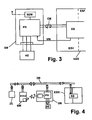
- FIG. 2 shows a preferred embodiment of a connection possibility of a further control device to a brake control device EBS, which is shown only in partial detail here.
- the further control device WSE preferably contains a control module SM permanently installed on the trailer side as well as a portable operating module BM which can be arranged in the driver's cab of the towing vehicle and preferably can be removed from there and can be used mobile.
- Operating module BM and control module SM of the further control device WSE are advantageously via a communication link, preferably a wireless radio link in signal-transmitting connection.
- the further control device WSE advantageously contains at least one programmable electronic unit, for example a programmable microcontroller PR, which is preferably arranged in the control module SM.
- the operating module BM may also contain such a programmable electronic unit.
- Control module and control module each contain transmit-receive modules SEB and SEM, which may be divided into transmit modules and receive modules or may preferably form combined transceiver modules.
- the structure of the control module SM is sketched in Fig. 2 only schematically by showing the transceiver module SEM, a microcontroller PR and a terminal block KB without further peripheral circuit.
- Plotted are connection blocks for signal outputs AP and signal inputs EP of the controller, for signal inputs EM and signal outputs AM of the control module SM and for signal inputs EB and signal outputs of the brake control device EBS.
- the signal inputs and signal outputs are each numbered from 1 to 3 or 1 to 4 or 1 to 5 respectively.
- Individual connections or signals at individual connections are also mentioned below a terminal block, z. B. AP, and a number, for. B. 2, within this block by a combined name, eg. B. AP2, individually designated.
- input elements X1, X2, X3 of an input device to three different functions, which can be commanded by the user, of an actuator device AE in the vehicle trailer are provided in the operating module BM.
- By actuating the input elements X1, X2, X3 instruction signals can be transmitted to the control module SM via the wireless signal connection FV, which are detected in the control module SM and converted into output signals AP1, AP2 and AP3 at the output AP of the controller PR.
- the output signals of the controller are bivalent in a preferred simple embodiment and can be switched between two signal levels, in particular 0 volts and approximately supply voltage VW of the control module.
- the outputs AP1 to AP3 of the controller are advantageously connected via a multi-core cable to the input terminals EB of the brake control device, it being assumed that an output signal AP1 of the controller forms an input signal EB1 of the brake control device and given corresponding unique assignments for AP2-EB2 and AP3-EB3 are.
- the number of connections between outputs AP of the controller and inputs EB of the brake control devices is typically limited by limiting the number of inputs EB on the side of the brake control device.
- Signals transmitted by the controller via the outputs AP and the inputs EB to the brake control device EBS are fed to the programmable electronic unit ES of the brake control device and can there communicate with one another according to programmable assignment instructions and / or in particular with further information present in the brake control device.
- sensor signals to output signals of the electronic unit ES are linked.
- the output signals of the programmable electronic unit ES are supplied to the individual output terminals AB of the brake control device. These outputs AB are connected to inputs EM of the control module.
- the electrical supply power of the control module can be removed from the brake control device EBS by one of the outputs AB, set in the example shown, the output AB5, by appropriate programming of the electronic unit ES permanently and independently of input signals or sensor signals of the brake control device to a signal level is, which supplies the control module SM with electric power.
- a signal level VW is substantially equal to the supply voltage VV, with which also the brake control device EBS is supplied from the towing vehicle with electrical power.
- the electrical power supply of the control module SM from the electrical power supply of the brake control device EBS is particularly advantageous, as over the usual connectors between towing vehicle and trailer to supply various power consumers, in particular lighting devices of the trailer, no reliable permanent power supply of the control module SM is available with a suitable voltage level.
- the brake control device is supplied with electrical power via a separate line from the towing vehicle.
- the transmission of electrical supply power from the brake control device to the control module SM via one of the switchable signal outputs AB of the brake control device is particularly advantageous since these outputs are provided for user-configurable connection of consumers and the use of such an output terminal requires no further intervention in the brake control device EBS, in particular their connection to the towing vehicle in the safety-relevant section ESF.
- the output connections AB of the brake control device EBS are typically provided for switchable activation of actuators of the vehicle trailer assembly, the programmability of the electronic unit ES makes it possible to use such an output connection of the brake control device in the described particularly advantageous embodiment for the electrical power supply of the trailer-side control module.
- a connector connection can be prepared in the brake control device EBS.
- the output terminals AB1, AB2 and AB3 of the brake control device EBS are provided in the present case as signal lines for controlling several actuators of an actuator AE in the vehicle trailer with functions corresponding to the input elements X1, X2, X3 in the operating module.
- the individual output connections AB1, AB2 and AB3 of the brake control device can in principle be connected via individual lines directly to individual actuators of the actuator device AE for controlling the actuators.
- Particularly advantageous is a sketched in Fig. 2 embodiment, in which connecting lines from the outputs AB of the brake control device first the control module SM are supplied and there in a terminal block KB, which is representative of the branching of signal lines and not necessarily understood as a plurality of mechanical contact terminals must be, but also z.
- signals generated via the connecting lines between the outputs AB of the brake control device EBS and the inputs EM of the control module in the programmable unit ES of the brake control device which do not serve as drive signals for actuators, but only one or more signal inputs of the controller PR are supplied and serve in this for generating or modifying the signals at the outputs AP and / or for signals to the operating module via the radio link FV.
- the output terminal AB4 of the brake control device is used for this, via which z. B. a speed threshold signal is routed via the input terminal EM4 only to the input EP4 of the controller.
- the controller can also control an actuator via an output AM4 of the control module SM directly without detour via the brake control device.
- the multicore cable connections between outputs AP of the control module and inputs EB of the brake control device or between outputs AB of the brake control device and inputs EM of the control module can be carried out over multi-core cable with connector terminals, in particular on the side of the terminals EB and AB of the brake control device.
- the input terminals EM1, EM2 and EM3 of the control module SM are permanently assigned to the outputs AM1, AM2 and AM3 of the control module via the terminal block KB or a corresponding line branch. Such an assignment can also be made variable via the programmable controller, in which the terminal block KB contains wholly or partly electronically controllable switches.
- a first trailer function may be, for example, a lift axle function abbreviated to LA in FIG. 2, which controls the lifting or lowering of a lift axle of a multi-axle trailer.
- the brake control device can be prepared in a manner known per se for a load-dependent automatic control of an axle lift device by lifting the lift axle below a predefinable loading threshold and lowering the lift axle above the load threshold.
- the brake control device EBS independently controls a lift axle valve independently of the instruction signal via the signal output AB1 of the brake control device and the line guide through the control module.
- control signal from the output AB1 is also present as an input signal at the input EP1 of the controller PR, the current state of the axle lift device, ie lifted lift axle or lowered lift axle, as an input signal in the control module SM of the other control device WSE present and can there, especially in the control module BM will be displayed, which is considered permanent Display or only on request by the user can be done.
- an instruction signal by the user in the operating module BM also automatically set by the brake control device state of the Achsliftvor substances be changed by a corresponding signal in accordance with user input via the input element X1 to the control module in particular via the radio signal connection FV transmitted and is transmitted from the controller in a control signal at the output AP1 to the brake control device.
- an instruction signal of the user is advantageously linked with information available from sensor signals according to predeterminable assignment rules, for example also prescribed by legal provisions. For example, there are provisions that even with a fully loaded trailer lifting the lift axle for a limited period of 90 seconds or within a speed range up to 30 km / h is allowed.
- the link with the speed is in a simple manner possible in the programmable unit ES of the brake control device, since the speed information is constantly available there via wheel sensors.
- An instruction signal received from the control module SM to lift the lift axle lowered due to the automatic control can therefore be detected by the brake control device, e.g. B. accepted at low speed and implemented in a modified drive signal at the output AB1 for the axle lift.
- the brake control device e.g. B. accepted at low speed and implemented in a modified drive signal at the output AB1 for the axle lift.
- the request to raise the lift axle in such a case in the brake control device EBS or its programmable unit ES is ignored and the drive signal at the output AB1 remains in the lowered lift axle corresponding signal state.
- the signal input EP1 of the controller PR in the control module it is detected whether the given instruction to raise the lift axle, was accepted or ignored in the brake control device.
- a corresponding signal can be transmitted from the control module to the operating module and displayed there to the user.
- the time limit in the brake control device EBS can be monitored or such monitoring can take place in the control module SM by means of a time measuring device realized there.
- a lift axle automatically raised at low load on the trailer by the brake control means may be forcibly lowered by the user, but there are typically no restrictive provisions, but such limitations may be user-programmed in the control module SM or in the brake control means.
- Another exemplary trailer function is given by a pneumatically lowered to a driving position chassis, especially for a tipper trailer, in which a lowered chassis means a higher stability during tipping.
- a lowering of the chassis by venting the pneumatic bellows pneumatic suspension of the trailer is commanded by the user by means of the input element X2 in the control module, which via the radio signal connection FV and the control module, the delivery of a corresponding instruction signal via the output AP2 to the input EB2 of the brake control device leads.
- such an instruction signal can be linked with information about one or more operating state variables according to a prescribable rule; for example, it may be specified that a lowering of the chassis should only be permissible if the vehicle is traveling at a speed below a predetermined speed threshold moves and / or if the lateral inclination or the longitudinal inclination of the vehicle is smaller than predetermined angle threshold values relative to the horizontal.
- These parameters may also be associated with other operating state variables, such as the load, for. B. in such a way that at higher load the threshold values for the inclination angle are different than at lower load.
- the brake control device detects the presence of a request signal for lowering the chassis in its programmable unit ES and if the preprogrammed admissibility conditions are fulfilled at the same time, then the programmable unit ES changes the signal state at the output AB2 from the driving position of the chassis to the driving state corresponding to the lowered chassis, which acts as a drive signal z.
- the programmable unit ES changes the signal state at the output AB2 from the driving position of the chassis to the driving state corresponding to the lowered chassis, which acts as a drive signal z.
- B. pneumatic valves in the actuator device AE for the pneumatic vehicle suspension via the input EM2 and the output AM2 of the control module is passed.
- control signal output at the output AB2 for the associated actuator in the actuator device AE serves at the same time as the state of the chassis lowering signal indicating input signal at the input EP2 of the programmable controller PR in the control module and can be signaled to the user.
- the user may be commanded via the control module to extend and retract underrun protection at the rear of the trailer, to open and close a sliding roof over the trailer, to release or engage a latch of an extendible chassis, and similar functions.
- FIG. 2 shows a further special function which can be commanded via the input element X3 of the operating module, which relates to a so-called paver brake.
- the function of the paver brake is important during operation a tilting vehicle in conjunction with a paver, wherein the vehicle for continuously feeding the paver with covering material from the dump body of the vehicle bears against the paver and is pushed by the latter at its feed speed.
- the service brake system of the dump truck is subjected to a defined brake pressure.
- the user is given a corresponding instruction signal via the input element X3 of the operating module BM, which is transmitted by the control module via the output port AP3 to the input EB3 of the brake control device and its programmable unit ES.
- the request signal for applying the paver brake in turn to be subject to special conditions, for example, the condition that the paver brake is only allowed at a standstill or only at very low speeds of the dump truck.
- the speed information is constantly present in the brake control device, so that an admissibility check in the programmable unit ES of the brake control device is readily possible and when the admissibility conditions are fulfilled, a valid request signal for applying the paver brake is already present in the brake control device.
- a brake request signal for the service brake system is accepted by the brake control device EBS only via the brake pressure line BD or the data bus CB from the towing vehicle.
- Such an actuator may in particular be an electrically controllable pressure relief valve DV, which is fed from the compressed air reservoir of the trailer and at its output on a pneumatic line FD a to a preset value corresponding to the intended brake pressure for the paver brake releases a pneumatic signal which via a line branch is combined with the brake pressure line BD at the pneumatic control input of the brake control device EBS.
- This pneumatic brake request signal is accepted by the brake control device, such as a brake request signal triggered by pedal pressure of the driver, and converted into an application of the service brake system with the brake pressure intended for the paver brake. Since the paver brake is applied only during vehicle standstill or at very low speeds, such an intervention in the brake system is not critical.
- the permissibility of the application of the paver brake can be checked in the brake control device EBS or the further control device based on a link with a current speed signal and a signal at the output AB3 or AP3 can be suppressed if an admissibility criterion is not met.
- a brake control device EBS is set up such that a brake request signal is also possible via one of the inputs EB, the pressure limiting valve and the output AB3 of the brake control device assigned to it can be omitted, but the latter may also be retained as a confirmation signal to the further control device.
- the application of paver brake is then in the brake control device alone from the Request signal from the output AP3 of the control module of the further control device to the input EB3 of the brake control device causes, which may be predefined in the brake control device, the associated brake pressure for this braking request, so that the signal at the output AP3 can be designed only divalent.
- the brake pressure can also be coded in the brake request signal.
- an admissibility link for. B. be programmed with a speed signal, so that the paver brake can be applied only under certain conditions.
- a combination of instruction signals of the user with further conditions, in particular including operating state variables of the vehicle can alternatively or additionally be carried out in the further control device WSE itself in the brake control device EBS.
- Such operating state variables can be provided to the further control device WSE by the brake control device, for example speed threshold signals, as mentioned as an example to the output port AB4, or speed signals resolved in stages themselves.
- Such information signals can be requested by the brake control device EBS at regular intervals or on specific information request from the further control device to be transmitted to this.
- instruction signals are output by the control module via the signal connections AP-EB only as a switching signal and not as permanent signals, several output input connections can be coded as a digital word.
- a data bus is advantageously set up for a more extensive data transmission between brake control device and further control device, which is advantageously separated from it because of the safety regulations for using the data bus CB.
- Such a data bus may advantageously be of the type of CAN data buses frequently used in vehicles.
- FIG. 4 an embodiment is sketched in which such a data bus CM is set up between the programmable controller PR of the control module SM and the programmable unit ES of the brake control device EBS.
- operating state signals for example sensor signals of the sensor arrangement SA connected to the brake control device or signals derived therefrom, can be transmitted from the brake control device to the control module via the data bus CM.
- a check of, for example, admissibility criteria for specific instruction signals of the user can be carried out in the programmable unit ES of the brake control device similar to that described with reference to FIG.
- Fig. 3 is again schematically indicated the electrical power supply of the control module from the brake control unit with a supply voltage level VW.
- a data bus CM and a signal connection via discrete individual signal lines, as in FIG. 2, can be implemented in combination.
- the actuation of actuators of the actuator unit AE is only via the control module SM directly provided.
- actuators it is also possible for actuators to be connected to the brake control device in a controllable manner.
- a data bus connection CM is provided between the brake control device EBS and the control module SM of the further control device
- a data bus DB is provided, to which besides the brake control device EBS and the control module SM also devices ZE in the towing vehicle and The operating module BM can also be connected via an interface located there.
- a communication between the operating module BM and the control module SM can take place both via the data bus DB and via the radio signal connection FV, wherein a distinction according to the type of signals to be exchanged can be made, for example by signals from the control module SM to trigger displays in the operating module BM unrestricted data bus DB and / or radio signal connection FV are transferable, whereas instruction signals for triggering actuator functions in the trailer are partially possible only via the data bus DB, so that such instructions can be given only during the presence of the driver in the towing vehicle, not inadvertently when the operating module BM is taken outside the vehicle.
- a preferred embodiment of an operating module BM is sketched by its simplicity.
- This contains a plurality of input elements X1, X2, X3 as in the example of FIG. 2.
- These input elements are designed as pushbutton switching elements, in particular as mechanical pushbuttons, but also as touch input fields or membrane pushbuttons.
- a signal transmission takes place between the operating module and control module via the radio link FV advantageously via a multi-channel radio link, each channel one of the command elements X1, X2 and X3 commandable trailer functions assigned.
- the execution of the input elements as a pure probe is particularly simple and inexpensive and especially for the detached from the vehicle storage of the operating module in clothing bags or the like of particular advantage.
- switchable functions such as the described functions of forcibly lifting or lowering a lift axle, lowering and raising a chassis, applying or releasing a paver brake
- only one probe element is provided for each function, and the effect triggered by actuation of the probe element to a function can be determined via the programming of the further control device.
- the operating module also contains for each commandable function display elements, which are preferably designed as light-emitting diodes.
- each commandable function display elements which are preferably designed as light-emitting diodes.
- two display elements are provided for each function, which are made distinguishable for example by different shape, color or arrangement for the user. Particularly advantageous is the combination of several such differentiation criteria.
- the display elements for the various functions are spatially assigned to the respective input elements.
- three input elements X1, X2, X3 are arranged in a row and associated display elements are arranged in pairs transverse to the row direction of the input elements in direct proximity thereto.
- the input element X1 is assigned two display elements AZ11, AZ12 and arranged directly above the display element X1.
- display elements AZ21, AZ22 are to the input element X2 and display elements AZ31, AZ32 provided to the display element X3 and arranged.
- the display elements AZ12, AZ22 and AZ32 are formed as triangle symbols with the tip pointing downward, the display symbols AZ11, AZ21 and AZ31 as triangular symbols with the tip pointing upwards.
- the display elements AZ11, AZ21 and AZ31 on a mutually identical, different from the display elements AZ12, AZ22 and AZ32 luminescent color.
- the operating module may include a programmable controller module PRB, which on the one hand recognizes the input signals via the input elements X1, X2, X3 and on the other controls the display element and handles the communication with the control module in the trailer via the radio link FV or optionally a data bus connection.
- PRB programmable controller module
- the associated display elements AZ11, AZ12 indicate the current operating state of the lift axle, for example, at currently raised lift axle, the upper display element AZ11, at lowered lift axle, the lower display element AZ12 lights up.
- the current status of the respective function is advantageously only at the first actuation of the input element via the radio link FV from the control module SM, in which the current state of the signal at the input EP1 of FIG. 3 can be removed, is queried.
- a time-limited repeat interval of, for example, a duration between 3 and 10 seconds following the first actuation of the input element X1 or the presence of the current state signal to the function
- the user can change the displayed status of the assigned function by re-actuating the input element X1 instruct or, if the displayed status of the function of its intended Setting to maintain this by omitting a re-actuation of the input element.
- the display elements can also continuously display the current status of the respective trailer function or of the associated actuator.
- the actuation interval can then be advantageously highlighted by an additional signal, for example flashing display or an accompanying acoustic signal.
- the described preferred embodiment of an operating module is characterized by a particularly simple and inexpensive construction, which is also favorable in terms of consequential costs by replacing lost or damaged control modules.
- operating module and associated trailer-side control module in a conventional manner can be individually matched and the communication between paired control module and control module be coded individually.
- a vote of a control module to a specific control module for example, by exchanging individual data on a special connection on the trailer side.
Priority Applications (2)
| Application Number | Priority Date | Filing Date | Title |
|---|---|---|---|
| SI200632050A SI1698535T1 (sl) | 2005-06-03 | 2006-05-09 | Naprava za priklopnik, ki vsebuje sistem za nadzor zavor in dodatni nadzorni sistem |
| PL06009489T PL1698535T3 (pl) | 2005-06-03 | 2006-05-09 | Układ przyczepy ze sterownikiem hamulca i kolejnym sterownikiem dla takiego układu przyczepy |
Applications Claiming Priority (1)
| Application Number | Priority Date | Filing Date | Title |
|---|---|---|---|
| DE102005025622A DE102005025622A1 (de) | 2005-06-03 | 2005-06-03 | Fahrzeuganhängeranordnung mit einer Bremssteuereinrichtung und weitere Steuereinrichtung für eine solche Fahrzeuganhängeranordnung |
Publications (3)
| Publication Number | Publication Date |
|---|---|
| EP1698535A2 true EP1698535A2 (fr) | 2006-09-06 |
| EP1698535A3 EP1698535A3 (fr) | 2006-12-06 |
| EP1698535B1 EP1698535B1 (fr) | 2016-02-24 |
Family
ID=36672812
Family Applications (1)
| Application Number | Title | Priority Date | Filing Date |
|---|---|---|---|
| EP06009489.3A Active EP1698535B1 (fr) | 2005-06-03 | 2006-05-09 | Dispositif pour remorque comprennant une système de réglage de freinage avec en outre une autre systeme de réglage |
Country Status (6)
| Country | Link |
|---|---|
| EP (1) | EP1698535B1 (fr) |
| DE (1) | DE102005025622A1 (fr) |
| ES (1) | ES2570996T3 (fr) |
| HU (1) | HUE027774T2 (fr) |
| PL (1) | PL1698535T3 (fr) |
| SI (1) | SI1698535T1 (fr) |
Cited By (8)
| Publication number | Priority date | Publication date | Assignee | Title |
|---|---|---|---|---|
| EP2307247A2 (fr) | 2008-07-01 | 2011-04-13 | WABCO GmbH | Frein pour finisseuse |
| WO2011054424A1 (fr) | 2009-10-27 | 2011-05-12 | Robert Bosch Gmbh | Système de freinage adaptatif pour remorque de charge |
| WO2013124730A1 (fr) * | 2012-02-20 | 2013-08-29 | Knorr-Bremse Systeme Fur Nutzfahrzeuge Gmbh | Appariement de points d'accès de remorque |
| EP2717240A3 (fr) * | 2012-09-17 | 2014-08-13 | Knorr-Bremse Systems for Commercial Vehicles Limited | Appariement de point d'accès de remorque |
| WO2016058679A1 (fr) * | 2014-10-14 | 2016-04-21 | Wabco Gmbh | Système électronique de freinage pour véhicule |
| EP2313297B2 (fr) † | 2008-08-23 | 2017-03-15 | Haldex Brake Products Limited | Véhicule destiné à la pose d'un matériau de revêtement routier |
| WO2018041328A1 (fr) * | 2016-08-29 | 2018-03-08 | Volvo Truck Corporation | Évacuation d'air d'une suspension pneumatique pour améliorer les performances de freinage |
| US20210237574A1 (en) * | 2020-02-05 | 2021-08-05 | Paccar Inc | Dynamic chassis and tire status indications |
Families Citing this family (8)
| Publication number | Priority date | Publication date | Assignee | Title |
|---|---|---|---|---|
| DE102008028913B4 (de) * | 2008-06-18 | 2017-02-09 | Knorr-Bremse Systeme für Nutzfahrzeuge GmbH | Überwachungsvorrichtung einer Zugfahrzeug-Anhänger-Kombination |
| DE102013014672A1 (de) | 2013-09-04 | 2015-03-05 | Wabco Gmbh | Verfahren zur Steuerung eines elektronischen Bremssystems |
| DE102013015159A1 (de) * | 2013-09-11 | 2015-03-12 | Wabco Gmbh | Verfahren zur Bestimmung der Laufleistung einer Achse |
| DE202015104525U1 (de) | 2015-08-26 | 2016-12-01 | Alois Kober Gmbh | Schlingerbremseinrichtung |
| DE102016210244A1 (de) * | 2016-06-09 | 2017-12-14 | Continental Teves Ag & Co. Ohg | Bremssystem mit einem Bremsen-Eingriffsbeschränker für Komfort- und Sicherheitsfunktionen in einem Fahrzeug |
| DE102017000547A1 (de) | 2017-01-21 | 2018-07-26 | Wabco Gmbh | Verfahren zur Verzögerung eines Anhängefahrzeugs, Radmodul zur Durchführung des Verfahrens sowie Fahrzeugkombination mit einem solchen Radmodul |
| EP3392084B1 (fr) | 2017-04-20 | 2021-01-20 | Schmitz Cargobull AG | Remorque de véhicule utilitaire |
| PL3392085T3 (pl) | 2017-04-20 | 2022-07-11 | Schmitz Cargobull Ag | Przyczepa pojazdu użytkowego |
Citations (11)
| Publication number | Priority date | Publication date | Assignee | Title |
|---|---|---|---|---|
| EP0467112A2 (fr) * | 1990-07-17 | 1992-01-22 | WABCO GmbH | Système de freinage électronique pour véhicules |
| DE4227083A1 (de) * | 1992-08-17 | 1994-02-24 | Bosch Gmbh Robert | Elektronisches Bremssystem, insbesondere für Straßenfahrzeuge |
| US5690347A (en) * | 1996-04-15 | 1997-11-25 | Tractor Trailer Safety Systems, Inc. | Tractor trailer integrated jackknife control device |
| GB2363435A (en) * | 2000-06-17 | 2001-12-19 | Knorr Bremse Systeme | Transfering vehicle parameters for electronic brake control |
| US6411206B1 (en) * | 1996-10-11 | 2002-06-25 | Indian Head Industries, Inc. | Brake monitoring system |
| DE10137148A1 (de) * | 2001-07-30 | 2003-02-13 | Knorr Bremse Systeme | Bremsanlage für Nutzfahrzeuganhänger |
| US20030168908A1 (en) * | 1999-04-14 | 2003-09-11 | United States Gear Corporation | Towed vehicle brake controller |
| DE10216564A1 (de) * | 2002-04-15 | 2003-10-23 | Wabco Gmbh & Co Ohg | Verfahren zum Datenaustausch in einem Fahrzeug, bei dem die einzelnen Fahrzeugteile über einen PLC-Datenbus miteinander verbunden sind |
| US20030222774A1 (en) * | 2002-06-04 | 2003-12-04 | Hi-Tech Transport Electronics, Inc. | Vehicle brake monitoring system |
| DE10310235A1 (de) * | 2003-03-08 | 2004-09-16 | Wabco Gmbh & Co. Ohg | Steuereinrichtung für Anhängefahrzeug |
| EP1504975A1 (fr) * | 2003-08-08 | 2005-02-09 | WABCO GmbH & CO. OHG | Système de freinage pour un véhicule utilisant un moyen de pression |
-
2005
- 2005-06-03 DE DE102005025622A patent/DE102005025622A1/de active Pending
-
2006
- 2006-05-09 EP EP06009489.3A patent/EP1698535B1/fr active Active
- 2006-05-09 SI SI200632050A patent/SI1698535T1/sl unknown
- 2006-05-09 ES ES06009489T patent/ES2570996T3/es active Active
- 2006-05-09 PL PL06009489T patent/PL1698535T3/pl unknown
- 2006-05-09 HU HUE06009489A patent/HUE027774T2/en unknown
Patent Citations (11)
| Publication number | Priority date | Publication date | Assignee | Title |
|---|---|---|---|---|
| EP0467112A2 (fr) * | 1990-07-17 | 1992-01-22 | WABCO GmbH | Système de freinage électronique pour véhicules |
| DE4227083A1 (de) * | 1992-08-17 | 1994-02-24 | Bosch Gmbh Robert | Elektronisches Bremssystem, insbesondere für Straßenfahrzeuge |
| US5690347A (en) * | 1996-04-15 | 1997-11-25 | Tractor Trailer Safety Systems, Inc. | Tractor trailer integrated jackknife control device |
| US6411206B1 (en) * | 1996-10-11 | 2002-06-25 | Indian Head Industries, Inc. | Brake monitoring system |
| US20030168908A1 (en) * | 1999-04-14 | 2003-09-11 | United States Gear Corporation | Towed vehicle brake controller |
| GB2363435A (en) * | 2000-06-17 | 2001-12-19 | Knorr Bremse Systeme | Transfering vehicle parameters for electronic brake control |
| DE10137148A1 (de) * | 2001-07-30 | 2003-02-13 | Knorr Bremse Systeme | Bremsanlage für Nutzfahrzeuganhänger |
| DE10216564A1 (de) * | 2002-04-15 | 2003-10-23 | Wabco Gmbh & Co Ohg | Verfahren zum Datenaustausch in einem Fahrzeug, bei dem die einzelnen Fahrzeugteile über einen PLC-Datenbus miteinander verbunden sind |
| US20030222774A1 (en) * | 2002-06-04 | 2003-12-04 | Hi-Tech Transport Electronics, Inc. | Vehicle brake monitoring system |
| DE10310235A1 (de) * | 2003-03-08 | 2004-09-16 | Wabco Gmbh & Co. Ohg | Steuereinrichtung für Anhängefahrzeug |
| EP1504975A1 (fr) * | 2003-08-08 | 2005-02-09 | WABCO GmbH & CO. OHG | Système de freinage pour un véhicule utilisant un moyen de pression |
Cited By (14)
| Publication number | Priority date | Publication date | Assignee | Title |
|---|---|---|---|---|
| EP2307247A2 (fr) | 2008-07-01 | 2011-04-13 | WABCO GmbH | Frein pour finisseuse |
| EP2307247B1 (fr) * | 2008-07-01 | 2017-10-18 | WABCO GmbH | Frein pour finisseuse |
| EP2313297B2 (fr) † | 2008-08-23 | 2017-03-15 | Haldex Brake Products Limited | Véhicule destiné à la pose d'un matériau de revêtement routier |
| WO2011054424A1 (fr) | 2009-10-27 | 2011-05-12 | Robert Bosch Gmbh | Système de freinage adaptatif pour remorque de charge |
| WO2013124730A1 (fr) * | 2012-02-20 | 2013-08-29 | Knorr-Bremse Systeme Fur Nutzfahrzeuge Gmbh | Appariement de points d'accès de remorque |
| US9260078B2 (en) | 2012-02-20 | 2016-02-16 | Knorr-Bremse System Fur Nutzfahrzeuge Gmbh | Trailer access point pairing |
| EP2717240A3 (fr) * | 2012-09-17 | 2014-08-13 | Knorr-Bremse Systems for Commercial Vehicles Limited | Appariement de point d'accès de remorque |
| WO2016058679A1 (fr) * | 2014-10-14 | 2016-04-21 | Wabco Gmbh | Système électronique de freinage pour véhicule |
| WO2018041328A1 (fr) * | 2016-08-29 | 2018-03-08 | Volvo Truck Corporation | Évacuation d'air d'une suspension pneumatique pour améliorer les performances de freinage |
| CN109923014A (zh) * | 2016-08-29 | 2019-06-21 | 沃尔沃卡车集团 | 用于提高制动性能的空气悬架排空 |
| US10940733B2 (en) | 2016-08-29 | 2021-03-09 | Volvo Truck Corporation | Air suspension evacuation for improved braking performance |
| CN109923014B (zh) * | 2016-08-29 | 2021-07-13 | 沃尔沃卡车集团 | 用于车辆的负载传递装置、负载传递方法和车辆 |
| US20210237574A1 (en) * | 2020-02-05 | 2021-08-05 | Paccar Inc | Dynamic chassis and tire status indications |
| US11623519B2 (en) * | 2020-02-05 | 2023-04-11 | Paccar Inc. | Dynamic chassis and tire status indications |
Also Published As
| Publication number | Publication date |
|---|---|
| ES2570996T3 (es) | 2016-05-23 |
| SI1698535T1 (sl) | 2016-06-30 |
| HUE027774T2 (en) | 2016-10-28 |
| DE102005025622A1 (de) | 2006-10-19 |
| EP1698535A3 (fr) | 2006-12-06 |
| PL1698535T3 (pl) | 2016-07-29 |
| EP1698535B1 (fr) | 2016-02-24 |
Similar Documents
| Publication | Publication Date | Title |
|---|---|---|
| EP1698535B1 (fr) | Dispositif pour remorque comprennant une système de réglage de freinage avec en outre une autre systeme de réglage | |
| DE10216564B4 (de) | Verfahren zum Datenaustausch in einem Fahrzeug, bei dem die einzelnen Fahrzeugteile über einen PLC-Datenbus miteinander verbunden sind | |
| EP0520147B1 (fr) | Dispositif de commande volontaire de montée ou de descente de la carrosserie de véhicules à suspension pneumatique | |
| EP3600991B1 (fr) | Frein à main électro-pneumatique avec tcv integré (commande scandinave) | |
| EP2055542B1 (fr) | Dispositif de frein actionné par un moyen de pression d'un véhicule sur rail doté d'un module de frein fixe produisant une pression contraire pour des freins de remorque | |
| EP3123697B1 (fr) | Procédé d'établissement d'une liaison sans fil | |
| EP1923284B1 (fr) | Dispositif de freinage à laminoir pour véhicules automobiles | |
| DE102008060912B4 (de) | Pneumatische Bremsanlage mit einem Parkventil | |
| EP3600993A1 (fr) | Système de freinage pouvant être commandé de manière électronique ainsi que procédé servant à commander le système de freinage pouvant être commandé de manière électronique | |
| DE102007038472B4 (de) | Ventilanordnung zur Steuerung einer Bremsanlage eines Anhängerfahrzeugs | |
| EP0467112A2 (fr) | Système de freinage électronique pour véhicules | |
| EP3022099A1 (fr) | Dispositif de freinage de stationnement pour un véhicule tracteur d'une combinaison de véhicule tracteur-remorque présentant un dispositif de soupape pour frein de maintien en ligne pouvant être rattrapé | |
| EP1926645A1 (fr) | Procede pour commander une installation de freinage pneumatique | |
| EP3072716A1 (fr) | Soufflet pneumatique | |
| EP0278228B1 (fr) | Installation de freinage électro-pneumatique pour véhicules de traction | |
| DE102017002391A1 (de) | Elektronisches Bremssystem für einen Anhänger | |
| WO2011161156A1 (fr) | Chariot de manutention équipé d'une lampe de travail et procédé d'allumage et d'extinction | |
| EP1886848A1 (fr) | Appareil de raccordement de remorque électrique | |
| EP2617615B1 (fr) | Installation de freinage pneumatique d'une remorque | |
| EP2082932B1 (fr) | Système de frein de service pour un véhicule et procédé de fonctionnement d'un système de frein de service | |
| DE102004056123A1 (de) | Nutzfahrzeug | |
| EP2468594B1 (fr) | Soupape de frein de stationnement et système de frein de stationnement équipé de celle-ci, ainsi que véhicule et procédé de commande d'un système de frein de stationnement | |
| EP3582981B1 (fr) | Module de commande d'attelage pour un attelage de remorque | |
| DE102019117650A1 (de) | Elektropneumatisches Handbrems-System für Nutzfahrzeuge mit Federspeicher-Feststellbremsen | |
| DE102005032056A1 (de) | Fahrzeugführungssystem mit zentralem Steuergerät für sämtliche Fahrzeugführungsfunktionen |
Legal Events
| Date | Code | Title | Description |
|---|---|---|---|
| PUAI | Public reference made under article 153(3) epc to a published international application that has entered the european phase |
Free format text: ORIGINAL CODE: 0009012 |
|
| AK | Designated contracting states |
Kind code of ref document: A2 Designated state(s): AT BE BG CH CY CZ DE DK EE ES FI FR GB GR HU IE IS IT LI LT LU LV MC NL PL PT RO SE SI SK TR |
|
| AX | Request for extension of the european patent |
Extension state: AL BA HR MK YU |
|
| RAP1 | Party data changed (applicant data changed or rights of an application transferred) |
Owner name: KOMPLED GMBH & CO. KG |
|
| PUAL | Search report despatched |
Free format text: ORIGINAL CODE: 0009013 |
|
| AK | Designated contracting states |
Kind code of ref document: A3 Designated state(s): AT BE BG CH CY CZ DE DK EE ES FI FR GB GR HU IE IS IT LI LT LU LV MC NL PL PT RO SE SI SK TR |
|
| AX | Request for extension of the european patent |
Extension state: AL BA HR MK YU |
|
| RIC1 | Information provided on ipc code assigned before grant |
Ipc: B60T 17/22 20060101ALI20061102BHEP Ipc: B60T 8/32 20060101ALI20061102BHEP Ipc: B60T 13/66 20060101AFI20060728BHEP |
|
| RAP1 | Party data changed (applicant data changed or rights of an application transferred) |
Owner name: SCHMITZ GOTHA FAHRZEUGWERKE GMBH |
|
| 17P | Request for examination filed |
Effective date: 20070118 |
|
| 17Q | First examination report despatched |
Effective date: 20070222 |
|
| AKX | Designation fees paid |
Designated state(s): AT BE BG CH CY CZ DE DK EE ES FI FR GB GR HU IE IS IT LI LT LU LV MC NL PL PT RO SE SI SK TR |
|
| RAP1 | Party data changed (applicant data changed or rights of an application transferred) |
Owner name: SCHMITZ CARGOBULL GOTHA GMBH |
|
| APAI | Date of receipt of notice of appeal modified |
Free format text: ORIGINAL CODE: EPIDOSCNOA2E |
|
| APBK | Appeal reference recorded |
Free format text: ORIGINAL CODE: EPIDOSNREFNE |
|
| APBN | Date of receipt of notice of appeal recorded |
Free format text: ORIGINAL CODE: EPIDOSNNOA2E |
|
| APBR | Date of receipt of statement of grounds of appeal recorded |
Free format text: ORIGINAL CODE: EPIDOSNNOA3E |
|
| APAF | Appeal reference modified |
Free format text: ORIGINAL CODE: EPIDOSCREFNE |
|
| APBT | Appeal procedure closed |
Free format text: ORIGINAL CODE: EPIDOSNNOA9E |
|
| RIC1 | Information provided on ipc code assigned before grant |
Ipc: B60T 13/66 20060101AFI20150819BHEP Ipc: B60T 17/22 20060101ALI20150819BHEP Ipc: B60T 8/32 20060101ALI20150819BHEP Ipc: B60T 8/17 20060101ALI20150819BHEP |
|
| GRAP | Despatch of communication of intention to grant a patent |
Free format text: ORIGINAL CODE: EPIDOSNIGR1 |
|
| INTG | Intention to grant announced |
Effective date: 20151023 |
|
| GRAS | Grant fee paid |
Free format text: ORIGINAL CODE: EPIDOSNIGR3 |
|
| GRAA | (expected) grant |
Free format text: ORIGINAL CODE: 0009210 |
|
| AK | Designated contracting states |
Kind code of ref document: B1 Designated state(s): AT BE BG CH CY CZ DE DK EE ES FI FR GB GR HU IE IS IT LI LT LU LV MC NL PL PT RO SE SI SK TR |
|
| REG | Reference to a national code |
Ref country code: GB Ref legal event code: FG4D Free format text: NOT ENGLISH |
|
| REG | Reference to a national code |
Ref country code: CH Ref legal event code: EP |
|
| REG | Reference to a national code |
Ref country code: AT Ref legal event code: REF Ref document number: 776519 Country of ref document: AT Kind code of ref document: T Effective date: 20160315 |
|
| REG | Reference to a national code |
Ref country code: IE Ref legal event code: FG4D Free format text: LANGUAGE OF EP DOCUMENT: GERMAN |
|
| REG | Reference to a national code |
Ref country code: DE Ref legal event code: R096 Ref document number: 502006014760 Country of ref document: DE |
|
| REG | Reference to a national code |
Ref country code: PT Ref legal event code: SC4A Free format text: AVAILABILITY OF NATIONAL TRANSLATION Effective date: 20160505 |
|
| REG | Reference to a national code |
Ref country code: RO Ref legal event code: EPE |
|
| REG | Reference to a national code |
Ref country code: ES Ref legal event code: FG2A Ref document number: 2570996 Country of ref document: ES Kind code of ref document: T3 Effective date: 20160523 |
|
| REG | Reference to a national code |
Ref country code: NL Ref legal event code: FP |
|
| REG | Reference to a national code |
Ref country code: LT Ref legal event code: MG4D |
|
| PGFP | Annual fee paid to national office [announced via postgrant information from national office to epo] |
Ref country code: NL Payment date: 20160523 Year of fee payment: 11 |
|
| PG25 | Lapsed in a contracting state [announced via postgrant information from national office to epo] |
Ref country code: FI Free format text: LAPSE BECAUSE OF FAILURE TO SUBMIT A TRANSLATION OF THE DESCRIPTION OR TO PAY THE FEE WITHIN THE PRESCRIBED TIME-LIMIT Effective date: 20160224 Ref country code: GR Free format text: LAPSE BECAUSE OF FAILURE TO SUBMIT A TRANSLATION OF THE DESCRIPTION OR TO PAY THE FEE WITHIN THE PRESCRIBED TIME-LIMIT Effective date: 20160525 |
|
| PGFP | Annual fee paid to national office [announced via postgrant information from national office to epo] |
Ref country code: BG Payment date: 20160520 Year of fee payment: 11 |
|
| PG25 | Lapsed in a contracting state [announced via postgrant information from national office to epo] |
Ref country code: LT Free format text: LAPSE BECAUSE OF FAILURE TO SUBMIT A TRANSLATION OF THE DESCRIPTION OR TO PAY THE FEE WITHIN THE PRESCRIBED TIME-LIMIT Effective date: 20160224 Ref country code: SE Free format text: LAPSE BECAUSE OF FAILURE TO SUBMIT A TRANSLATION OF THE DESCRIPTION OR TO PAY THE FEE WITHIN THE PRESCRIBED TIME-LIMIT Effective date: 20160224 |
|
| PGFP | Annual fee paid to national office [announced via postgrant information from national office to epo] |
Ref country code: SI Payment date: 20160429 Year of fee payment: 11 Ref country code: PT Payment date: 20160511 Year of fee payment: 11 |
|
| REG | Reference to a national code |
Ref country code: SK Ref legal event code: T3 Ref document number: E 20838 Country of ref document: SK |
|
| REG | Reference to a national code |
Ref country code: HU Ref legal event code: AG4A Ref document number: E027774 Country of ref document: HU |
|
| PG25 | Lapsed in a contracting state [announced via postgrant information from national office to epo] |
Ref country code: EE Free format text: LAPSE BECAUSE OF FAILURE TO SUBMIT A TRANSLATION OF THE DESCRIPTION OR TO PAY THE FEE WITHIN THE PRESCRIBED TIME-LIMIT Effective date: 20160224 Ref country code: DK Free format text: LAPSE BECAUSE OF FAILURE TO SUBMIT A TRANSLATION OF THE DESCRIPTION OR TO PAY THE FEE WITHIN THE PRESCRIBED TIME-LIMIT Effective date: 20160224 |
|
| REG | Reference to a national code |
Ref country code: DE Ref legal event code: R097 Ref document number: 502006014760 Country of ref document: DE |
|
| PGFP | Annual fee paid to national office [announced via postgrant information from national office to epo] |
Ref country code: SK Payment date: 20160429 Year of fee payment: 11 |
|
| PG25 | Lapsed in a contracting state [announced via postgrant information from national office to epo] |
Ref country code: LU Free format text: LAPSE BECAUSE OF FAILURE TO SUBMIT A TRANSLATION OF THE DESCRIPTION OR TO PAY THE FEE WITHIN THE PRESCRIBED TIME-LIMIT Effective date: 20160509 |
|
| PLBE | No opposition filed within time limit |
Free format text: ORIGINAL CODE: 0009261 |
|
| REG | Reference to a national code |
Ref country code: CH Ref legal event code: PL |
|
| STAA | Information on the status of an ep patent application or granted ep patent |
Free format text: STATUS: NO OPPOSITION FILED WITHIN TIME LIMIT |
|
| GBPC | Gb: european patent ceased through non-payment of renewal fee |
Effective date: 20160524 |
|
| PG25 | Lapsed in a contracting state [announced via postgrant information from national office to epo] |
Ref country code: LI Free format text: LAPSE BECAUSE OF NON-PAYMENT OF DUE FEES Effective date: 20160531 Ref country code: CH Free format text: LAPSE BECAUSE OF NON-PAYMENT OF DUE FEES Effective date: 20160531 |
|
| 26N | No opposition filed |
Effective date: 20161125 |
|
| REG | Reference to a national code |
Ref country code: IE Ref legal event code: MM4A |
|
| REG | Reference to a national code |
Ref country code: FR Ref legal event code: ST Effective date: 20170131 |
|
| PG25 | Lapsed in a contracting state [announced via postgrant information from national office to epo] |
Ref country code: FR Free format text: LAPSE BECAUSE OF NON-PAYMENT OF DUE FEES Effective date: 20160531 |
|
| PG25 | Lapsed in a contracting state [announced via postgrant information from national office to epo] |
Ref country code: GB Free format text: LAPSE BECAUSE OF NON-PAYMENT OF DUE FEES Effective date: 20160524 Ref country code: IE Free format text: LAPSE BECAUSE OF NON-PAYMENT OF DUE FEES Effective date: 20160509 |
|
| PGFP | Annual fee paid to national office [announced via postgrant information from national office to epo] |
Ref country code: CZ Payment date: 20170502 Year of fee payment: 12 Ref country code: RO Payment date: 20170502 Year of fee payment: 12 |
|
| PGFP | Annual fee paid to national office [announced via postgrant information from national office to epo] |
Ref country code: LV Payment date: 20170524 Year of fee payment: 12 |
|
| PGFP | Annual fee paid to national office [announced via postgrant information from national office to epo] |
Ref country code: HU Payment date: 20170428 Year of fee payment: 12 |
|
| REG | Reference to a national code |
Ref country code: NL Ref legal event code: MM Effective date: 20170601 |
|
| PG25 | Lapsed in a contracting state [announced via postgrant information from national office to epo] |
Ref country code: SK Free format text: LAPSE BECAUSE OF NON-PAYMENT OF DUE FEES Effective date: 20170509 |
|
| REG | Reference to a national code |
Ref country code: SK Ref legal event code: MM4A Ref document number: E 20838 Country of ref document: SK Effective date: 20170509 |
|
| PG25 | Lapsed in a contracting state [announced via postgrant information from national office to epo] |
Ref country code: PT Free format text: LAPSE BECAUSE OF NON-PAYMENT OF DUE FEES Effective date: 20171109 Ref country code: SI Free format text: LAPSE BECAUSE OF NON-PAYMENT OF DUE FEES Effective date: 20170510 |
|
| REG | Reference to a national code |
Ref country code: SI Ref legal event code: KO00 Effective date: 20180111 |
|
| PG25 | Lapsed in a contracting state [announced via postgrant information from national office to epo] |
Ref country code: NL Free format text: LAPSE BECAUSE OF NON-PAYMENT OF DUE FEES Effective date: 20170601 |
|
| PG25 | Lapsed in a contracting state [announced via postgrant information from national office to epo] |
Ref country code: CY Free format text: LAPSE BECAUSE OF FAILURE TO SUBMIT A TRANSLATION OF THE DESCRIPTION OR TO PAY THE FEE WITHIN THE PRESCRIBED TIME-LIMIT Effective date: 20160224 |
|
| PG25 | Lapsed in a contracting state [announced via postgrant information from national office to epo] |
Ref country code: MC Free format text: LAPSE BECAUSE OF FAILURE TO SUBMIT A TRANSLATION OF THE DESCRIPTION OR TO PAY THE FEE WITHIN THE PRESCRIBED TIME-LIMIT Effective date: 20160224 Ref country code: TR Free format text: LAPSE BECAUSE OF FAILURE TO SUBMIT A TRANSLATION OF THE DESCRIPTION OR TO PAY THE FEE WITHIN THE PRESCRIBED TIME-LIMIT Effective date: 20160224 Ref country code: IS Free format text: LAPSE BECAUSE OF FAILURE TO SUBMIT A TRANSLATION OF THE DESCRIPTION OR TO PAY THE FEE WITHIN THE PRESCRIBED TIME-LIMIT Effective date: 20160224 |
|
| PG25 | Lapsed in a contracting state [announced via postgrant information from national office to epo] |
Ref country code: RO Free format text: LAPSE BECAUSE OF NON-PAYMENT OF DUE FEES Effective date: 20180509 Ref country code: CZ Free format text: LAPSE BECAUSE OF NON-PAYMENT OF DUE FEES Effective date: 20180509 Ref country code: HU Free format text: LAPSE BECAUSE OF NON-PAYMENT OF DUE FEES Effective date: 20180510 Ref country code: BG Free format text: LAPSE BECAUSE OF NON-PAYMENT OF DUE FEES Effective date: 20171206 |
|
| PG25 | Lapsed in a contracting state [announced via postgrant information from national office to epo] |
Ref country code: LV Free format text: LAPSE BECAUSE OF NON-PAYMENT OF DUE FEES Effective date: 20180509 |
|
| PGFP | Annual fee paid to national office [announced via postgrant information from national office to epo] |
Ref country code: IT Payment date: 20210531 Year of fee payment: 16 |
|
| PGFP | Annual fee paid to national office [announced via postgrant information from national office to epo] |
Ref country code: BE Payment date: 20210519 Year of fee payment: 16 Ref country code: AT Payment date: 20210518 Year of fee payment: 16 Ref country code: ES Payment date: 20210618 Year of fee payment: 16 |
|
| REG | Reference to a national code |
Ref country code: AT Ref legal event code: MM01 Ref document number: 776519 Country of ref document: AT Kind code of ref document: T Effective date: 20220509 |
|
| REG | Reference to a national code |
Ref country code: BE Ref legal event code: MM Effective date: 20220531 |
|
| PG25 | Lapsed in a contracting state [announced via postgrant information from national office to epo] |
Ref country code: AT Free format text: LAPSE BECAUSE OF NON-PAYMENT OF DUE FEES Effective date: 20220509 |
|
| PG25 | Lapsed in a contracting state [announced via postgrant information from national office to epo] |
Ref country code: BE Free format text: LAPSE BECAUSE OF NON-PAYMENT OF DUE FEES Effective date: 20220531 |
|
| REG | Reference to a national code |
Ref country code: ES Ref legal event code: FD2A Effective date: 20230626 |
|
| PG25 | Lapsed in a contracting state [announced via postgrant information from national office to epo] |
Ref country code: IT Free format text: LAPSE BECAUSE OF NON-PAYMENT OF DUE FEES Effective date: 20220509 Ref country code: ES Free format text: LAPSE BECAUSE OF NON-PAYMENT OF DUE FEES Effective date: 20220510 |
|
| PGFP | Annual fee paid to national office [announced via postgrant information from national office to epo] |
Ref country code: DE Payment date: 20230531 Year of fee payment: 18 |
|
| PGFP | Annual fee paid to national office [announced via postgrant information from national office to epo] |
Ref country code: PL Payment date: 20230502 Year of fee payment: 18 |