EP1695753A1 - Filterelement mit Drainagerohr - Google Patents
Filterelement mit Drainagerohr Download PDFInfo
- Publication number
- EP1695753A1 EP1695753A1 EP06101623A EP06101623A EP1695753A1 EP 1695753 A1 EP1695753 A1 EP 1695753A1 EP 06101623 A EP06101623 A EP 06101623A EP 06101623 A EP06101623 A EP 06101623A EP 1695753 A1 EP1695753 A1 EP 1695753A1
- Authority
- EP
- European Patent Office
- Prior art keywords
- filter element
- filter medium
- drainage tube
- sealing element
- filter
- Prior art date
- Legal status (The legal status is an assumption and is not a legal conclusion. Google has not performed a legal analysis and makes no representation as to the accuracy of the status listed.)
- Granted
Links
- 238000007789 sealing Methods 0.000 claims abstract description 11
- 239000007788 liquid Substances 0.000 claims abstract description 7
- 238000000926 separation method Methods 0.000 claims description 2
- 239000007789 gas Substances 0.000 description 4
- 238000004519 manufacturing process Methods 0.000 description 2
- 238000004026 adhesive bonding Methods 0.000 description 1
- 238000002485 combustion reaction Methods 0.000 description 1
- 239000012530 fluid Substances 0.000 description 1
Images

Classifications
-
- B—PERFORMING OPERATIONS; TRANSPORTING
- B01—PHYSICAL OR CHEMICAL PROCESSES OR APPARATUS IN GENERAL
- B01D—SEPARATION
- B01D46/00—Filters or filtering processes specially modified for separating dispersed particles from gases or vapours
- B01D46/0027—Filters or filtering processes specially modified for separating dispersed particles from gases or vapours with additional separating or treating functions
- B01D46/003—Filters or filtering processes specially modified for separating dispersed particles from gases or vapours with additional separating or treating functions including coalescing means for the separation of liquid
- B01D46/0031—Filters or filtering processes specially modified for separating dispersed particles from gases or vapours with additional separating or treating functions including coalescing means for the separation of liquid with collecting, draining means
-
- B—PERFORMING OPERATIONS; TRANSPORTING
- B01—PHYSICAL OR CHEMICAL PROCESSES OR APPARATUS IN GENERAL
- B01D—SEPARATION
- B01D27/00—Cartridge filters of the throw-away type
- B01D27/08—Construction of the casing
-
- B—PERFORMING OPERATIONS; TRANSPORTING
- B01—PHYSICAL OR CHEMICAL PROCESSES OR APPARATUS IN GENERAL
- B01D—SEPARATION
- B01D29/00—Filters with filtering elements stationary during filtration, e.g. pressure or suction filters, not covered by groups B01D24/00 - B01D27/00; Filtering elements therefor
- B01D29/11—Filters with filtering elements stationary during filtration, e.g. pressure or suction filters, not covered by groups B01D24/00 - B01D27/00; Filtering elements therefor with bag, cage, hose, tube, sleeve or like filtering elements
- B01D29/13—Supported filter elements
- B01D29/15—Supported filter elements arranged for inward flow filtration
- B01D29/21—Supported filter elements arranged for inward flow filtration with corrugated, folded or wound sheets
-
- B—PERFORMING OPERATIONS; TRANSPORTING
- B01—PHYSICAL OR CHEMICAL PROCESSES OR APPARATUS IN GENERAL
- B01D—SEPARATION
- B01D35/00—Filtering devices having features not specifically covered by groups B01D24/00 - B01D33/00, or for applications not specifically covered by groups B01D24/00 - B01D33/00; Auxiliary devices for filtration; Filter housing constructions
- B01D35/30—Filter housing constructions
-
- B—PERFORMING OPERATIONS; TRANSPORTING
- B01—PHYSICAL OR CHEMICAL PROCESSES OR APPARATUS IN GENERAL
- B01D—SEPARATION
- B01D36/00—Filter circuits or combinations of filters with other separating devices
- B01D36/003—Filters in combination with devices for the removal of liquids
- B01D36/006—Purge means
-
- B—PERFORMING OPERATIONS; TRANSPORTING
- B01—PHYSICAL OR CHEMICAL PROCESSES OR APPARATUS IN GENERAL
- B01D—SEPARATION
- B01D46/00—Filters or filtering processes specially modified for separating dispersed particles from gases or vapours
- B01D46/0027—Filters or filtering processes specially modified for separating dispersed particles from gases or vapours with additional separating or treating functions
- B01D46/003—Filters or filtering processes specially modified for separating dispersed particles from gases or vapours with additional separating or treating functions including coalescing means for the separation of liquid
-
- B—PERFORMING OPERATIONS; TRANSPORTING
- B01—PHYSICAL OR CHEMICAL PROCESSES OR APPARATUS IN GENERAL
- B01D—SEPARATION
- B01D46/00—Filters or filtering processes specially modified for separating dispersed particles from gases or vapours
- B01D46/24—Particle separators, e.g. dust precipitators, using rigid hollow filter bodies
- B01D46/2403—Particle separators, e.g. dust precipitators, using rigid hollow filter bodies characterised by the physical shape or structure of the filtering element
- B01D46/2411—Filter cartridges
-
- B—PERFORMING OPERATIONS; TRANSPORTING
- B01—PHYSICAL OR CHEMICAL PROCESSES OR APPARATUS IN GENERAL
- B01D—SEPARATION
- B01D2271/00—Sealings for filters specially adapted for separating dispersed particles from gases or vapours
- B01D2271/02—Gaskets, sealings
-
- F—MECHANICAL ENGINEERING; LIGHTING; HEATING; WEAPONS; BLASTING
- F01—MACHINES OR ENGINES IN GENERAL; ENGINE PLANTS IN GENERAL; STEAM ENGINES
- F01M—LUBRICATING OF MACHINES OR ENGINES IN GENERAL; LUBRICATING INTERNAL COMBUSTION ENGINES; CRANKCASE VENTILATING
- F01M13/00—Crankcase ventilating or breathing
- F01M13/04—Crankcase ventilating or breathing having means for purifying air before leaving crankcase, e.g. removing oil
- F01M2013/0438—Crankcase ventilating or breathing having means for purifying air before leaving crankcase, e.g. removing oil with a filter
-
- Y—GENERAL TAGGING OF NEW TECHNOLOGICAL DEVELOPMENTS; GENERAL TAGGING OF CROSS-SECTIONAL TECHNOLOGIES SPANNING OVER SEVERAL SECTIONS OF THE IPC; TECHNICAL SUBJECTS COVERED BY FORMER USPC CROSS-REFERENCE ART COLLECTIONS [XRACs] AND DIGESTS
- Y10—TECHNICAL SUBJECTS COVERED BY FORMER USPC
- Y10S—TECHNICAL SUBJECTS COVERED BY FORMER USPC CROSS-REFERENCE ART COLLECTIONS [XRACs] AND DIGESTS
- Y10S55/00—Gas separation
- Y10S55/17—Compressed air water removal
Definitions
- the invention relates to a filter element, in particular a Beerentölelement, for the separation of a liquid with a drainage pipe, through which the deposited liquid can be removed, according to the preamble of claim 1.
- a drainage device containing the drainage pipe and a filter device are provided under protection.
- Filter elements according to the preamble are generally accessible state of the art. They are used for example for de-oiling compressed air in compressed air systems, which are fed by an oil-lubricated compressor. Another application is the de-oiling of crankcase gases of an internal combustion engine.
- filter elements which are flowed through from the inside to the outside, the separated liquid collects inside the filter cartridge, which is preferably cylindrical. From there it is sucked off with the help of a drainage tube, which extends into the interior of the filter cartridge.
- This drainage tube may be an integral part of the upper end plate of the filter element, so that a fixation in the position necessary for the suction is possible.
- a filter element with fixed drainage pipe is cumbersome to manufacture, which is why the filter element is less economical.
- the object of the invention is therefore to provide a filter element with drainage pipe, which is inexpensive to manufacture. This object is solved by the features of claim 1.
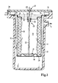
- the filter device according to FIG. 1 has a housing 11 with a cover 12, wherein an inlet 13 and an outlet 14 for the fluid to be filtered, in particular a gas, are formed by the housing. Between housing 11 and cover 12, a filter element 15 is held with an upper end plate 16 by means of a clamping connection. The filter element 15 also has a support body 17 and a lower end plate 18.
- the path of the gas to be filtered is indicated by arrows. It extends from the inlet 13 through openings, not shown, in the upper end disk 16 into an interior space 19 of the filter element 15, from where the gas stream is passed through a filter medium 20 and the likewise permeable support body 17 to the outlet 14. In this case, the deposited liquid collects in a recess 21 of the lower end plate 18, which can be sucked out of the inner space 19 through a drainage pipe 22.
- the drainage tube 22 is part of a drainage device 23, which among other things also has a connector 24 with snap-in lugs 25.
- the connector is thus designed as a plug-shaped component which can be inserted into a hole-shaped receptacle 26 in the end plate.
- the connector is placed on the drainage pipe 22 and glued to it.
- a sealing of the filter medium is carried out by gluing of its end faces 29 in corresponding paragraphs of the upper and lower end plate 16, 18th
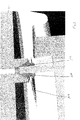
- FIG. 2 shows an embodiment in which a connecting piece 112 for a drainage pipe is provided on the cover 12.
- the connecting piece is designed conically in the direction of the drainage pipe.
- a seal 110 Within this design is a seal 110. This is knotted in a semicircular retaining plate 111.
Landscapes
- Chemical & Material Sciences (AREA)
- Chemical Kinetics & Catalysis (AREA)
- Physics & Mathematics (AREA)
- Geometry (AREA)
- Filtering Of Dispersed Particles In Gases (AREA)
Abstract
Description
- Die Erfindung betrifft ein Filterelement, insbesondere ein Luftentölelement, zur Abscheidung einer Flüssigkeit mit einem Drainagerohr, durch welches die abgeschiedene Flüssigkeit entfernt werden kann, nach dem Oberbegriff des Patentanspruches 1.
- Weiterhin sind eine das Drainagerohr enthaltende Drainageeinrichtung sowie eine Filtereinrichtung unter Schutz gestellt.
- Filterelemente nach dem Oberbegriff sind allgemein zugänglicher Stand der Technik. Sie werden beispielsweise zur Entölung von Druckluft in Druckluftsystemen verwendet, die durch einen ölgeschmierten Kompressor gespeist werden. Eine andere Anwendungsmöglichkeit ist die Entölung von Kurbelgehäusegasen einer Brennkraftmaschine. Bei Filterelementen, die von innen nach außen durchströmt werden, sammelt sich die abgeschiedene Flüssigkeit im Inneren der Filterpatrone, welche bevorzugt zylindrisch ausgeführt ist. Von dort wird sie mit Hilfe eines Drainagerohres abgesaugt, welches in das Innere der Filterpatrone hineinreicht. Dieses Drainagerohr kann integraler Bestandteil der oberen Endscheibe des Filterelementes sein, so dass eine Fixierung in der für die Absaugung notwendigen Lage möglich ist. Jedoch ist ein Filterelement mit fest eingebautem Drainagerohr umständlich in der Herstellung, weswegen das Filterelement wenig wirtschaftlich ist.
- Aufgabe der Erfindung ist es daher, ein Filterelement mit Drainagerohr zu schaffen, welches kostengünstig in der Herstellung ist. Diese Aufgabe wird durch die Merkmale des Patentanspruches 1 gelöst.
- Weitere Einzelheiten der Erfindung werden in der Zeichnung anhand von schematischen Ausführungsbeispielen beschrieben. Hierbei zeigt
- Figur 1
- die erfindungsgemäße Filtereinrichtung im Mittelschnitt,
- Figur 2
- ein Ausführungsbeispiel, bei dem lediglich die Abdichtung zwischen Deckel und Drainagerohr sichtbar ist und
- Figur 3
- eine weitere Ansicht der in Figur 2 gezeigten Darstellung.
- Die Filtereinrichtung gemäß Figur 1 weist ein Gehäuse 11 mit einem Deckel 12 auf wobei durch das Gehäuse ein Einlass 13 und ein Auslass 14 für das zu filternde Fluid, insbesondere ein Gas, gebildet ist. Zwischen Gehäuse 11 und Deckel 12 ist ein Filterelement 15 mit einer oberen Endscheibe 16 mittels einer Klemmverbindung gehalten. Das Filterelement 15 weist weiterhin einen Stützkörper 17 und eine untere Endscheibe 18 auf.
- Der Weg des zu filternden Gases ist durch Pfeile angedeutet. Er reicht vom Einlass 13 durch nicht dargestellte Öffnungen in der oberen Endscheibe 16 in einen Innenraum 19 des Filterelementes 15 hinein, von wo aus der Gasstrom durch ein Filtermedium 20 und den ebenfalls durchlässigen Stützkörper 17 zum Auslass 14 geleitet wird. Dabei sammelt sich in einer Vertiefung 21 der unteren Endscheibe 18 die abgeschiedene Flüssigkeit, welche durch ein Drainagerohr 22 aus dem Innenraum 19 herausgesogen werden kann.
- Das Drainagerohr 22 ist Teil einer Drainageeinrichtung 23, welche unter anderem auch einen Verbinder 24 mit Schnappnasen 25 aufweist. Der Verbinder ist also als stopfenförmiges Bauteil ausgestaltet, welches in eine lochförmige Aufnahme 26 in der Endscheibe gesteckt werden kann. Der Verbinder ist auf das Drainagerohr 22 gesteckt und mit diesem verklebt. Zur Dichtung des Drainagerohrs an einem Durchgang 27 im Deckel 12 sowie zur Dichtung zwischen Deckel 12 und Gehäuse 11 werden Dichtringe 28 verwendet. Eine Abdichtung des Filtermediums erfolgt durch Einkleben von dessen Stirnseiten 29 in entsprechende Absätze der oberen und unteren Endscheibe 16, 18.
- In Figur 2 ist eine Ausführung dargestellt, bei welcher am Deckel 12 ein Anschlussstutzen 112 für ein Drainagerohr vorgesehen ist. Der Anschlussstutzen ist in Richtung auf das Drainagerohr hin konisch gestaltet. Innerhalb dieser Gestaltung befindet sich eine Dichtung 110. Diese ist in ein halbkreisförmiges Halteblech 111 eingeknüpft.
- In Figur 3 ist ebenfalls in perspektivischer Schnittdarstellung nochmals dieser Aufbau gezeigt. Es ist ersichtlich, dass durch die Dichtung 110 eine zuverlässige Abdichtung des Drainagerohrs an dem Deckel 12 möglich ist. Außerdem besteht durch den Dichtungsaufbau und die Dichtungsgestaltung eine Möglichkeit des Toleranzausgleiches sowohl in x- als auch in y-Richtung.
Claims (4)
- Filterelement, insbesondere Luftentölelement, zur Abscheidung von einer Flüssigkeit, aufweisend ein ringförmig geschlossenes Filtermedium (20), welches an deren Stirnseiten (29) mit Endscheiben versehen ist, von denen eine untere Endscheibe (18) einen durch das Filtermedium gebildeten Innenraum (19) abschließt, in den ein Drainagerohr (22, 22a) hineinragt, dadurch gekennzeichnet, dass das Drainagerohr an der oberen Endscheibe (16) über ein Dichtungselement geführt ist, wobei das Dichtungselement am Behälterdeckel (12) dichtend anliegt.
- Filterelement nach Anspruch 1, dadurch gekennzeichnet, dass das Dichtungselement eine konische Dichtung (110) ist, welche in einer konischen Öffnung des Dekkels (12) eingefügt ist.
- Filterelement nach Anspruch 1 oder 1, dadurch gekennzeichnet, dass das Dichtungselement in eine Halteplatte (111) eingeknüpft ist.
- Filterelement nach einem der vorherigen Ansprüche, dadurch gekennzeichnet, dass das Dichtungselement einen inneren Hohlraum aufweist, der einen Toleranzausgleich in x- und/oder y-Richtung ermöglicht.
Applications Claiming Priority (1)
| Application Number | Priority Date | Filing Date | Title |
|---|---|---|---|
| DE102005009680 | 2005-02-28 |
Publications (2)
| Publication Number | Publication Date |
|---|---|
| EP1695753A1 true EP1695753A1 (de) | 2006-08-30 |
| EP1695753B1 EP1695753B1 (de) | 2014-06-04 |
Family
ID=36489642
Family Applications (1)
| Application Number | Title | Priority Date | Filing Date |
|---|---|---|---|
| EP06101623.4A Expired - Lifetime EP1695753B1 (de) | 2005-02-28 | 2006-02-14 | Filterelement mit Drainagerohr |
Country Status (2)
| Country | Link |
|---|---|
| US (1) | US7588615B2 (de) |
| EP (1) | EP1695753B1 (de) |
Cited By (13)
| Publication number | Priority date | Publication date | Assignee | Title |
|---|---|---|---|---|
| WO2011032818A1 (de) * | 2009-09-15 | 2011-03-24 | Mahle International Gmbh | Filtereinrichtung |
| WO2011039013A1 (de) * | 2009-09-30 | 2011-04-07 | Mahle International Gmbh | Filtereinrichtung |
| DE102016010692A1 (de) | 2016-09-06 | 2018-03-08 | Mann+Hummel Gmbh | Luftentölelement, Vorrichtung zur Abscheidung von Öl aus Rohluft sowie Verfahren zur Herstellung eines Luftentölelements |
| DE102017011691A1 (de) | 2017-12-18 | 2019-06-19 | Mann+Hummel Gmbh | Sensordrainageeinheit, Flüssigkeitsabscheider sowie Verfahren zur Drainagemengen-Steuerung eines Flüssigkeitsabscheiders |
| US10413851B2 (en) | 2014-07-03 | 2019-09-17 | Donaldson Company, Inc. | Fuel filter with water separator |
| US11207620B2 (en) | 2015-08-31 | 2021-12-28 | Cummins Filtration Ip, Inc. | Filter port seal |
| USD958288S1 (en) | 2020-10-09 | 2022-07-19 | Mahle International Gmbh | Filter device |
| US11426687B2 (en) | 2019-06-27 | 2022-08-30 | Mahle International Gmbh | Fuel filter |
| US11452956B2 (en) | 2019-06-27 | 2022-09-27 | Mahle International Gmbh | Fuel filter |
| USD967330S1 (en) | 2019-03-21 | 2022-10-18 | Mahle International Gmbh | Pin for a filter element |
| US11511217B2 (en) | 2020-09-22 | 2022-11-29 | Mahle International Gmbh | Filter and method of fabricating same |
| US11612843B2 (en) | 2015-06-26 | 2023-03-28 | Donaldson Company, Inc. | Composite media for fuel streams |
| US11992788B2 (en) | 2019-06-27 | 2024-05-28 | Mahle International Gmbh | Filter device |
Families Citing this family (16)
| Publication number | Priority date | Publication date | Assignee | Title |
|---|---|---|---|---|
| US7905947B2 (en) * | 2006-05-24 | 2011-03-15 | L.C. Eldridge Sales Co., Ltd. | Method and apparatus for removing contaminates from air |
| DE202007002786U1 (de) * | 2007-02-22 | 2008-06-26 | Mann+Hummel Gmbh | Fluidfilter mit einem in ein Filtergehäuse einsetzbaren Filterelement |
| CA2786559C (en) * | 2010-01-15 | 2017-05-02 | Ingersoll-Rand Company | Formed seal ring for a liquid gas separating element |
| JP5628089B2 (ja) * | 2011-05-19 | 2014-11-19 | 株式会社コガネイ | フィルタ |
| JP5666379B2 (ja) | 2011-05-19 | 2015-02-12 | 株式会社コガネイ | 旋回流発生器 |
| WO2012157515A1 (ja) | 2011-05-19 | 2012-11-22 | 株式会社コガネイ | フィルタ |
| DE102011080763A1 (de) | 2011-08-10 | 2013-02-14 | Ksm Water Gmbh | Filtereinrichtung und ein Verfahren zur Herstellung |
| DE102011110498A1 (de) * | 2011-08-17 | 2013-02-21 | Mann + Hummel Gmbh | Filter |
| US9352262B2 (en) | 2013-03-15 | 2016-05-31 | Donaldson Company, Inc. | Scavenge tube arrangement; gas liquid separator filter assembly; and methods |
| DE102014002719B4 (de) * | 2013-05-15 | 2017-10-12 | Mann + Hummel Gmbh | Abscheideelement und Flüssigkeitsabscheider zur Abscheidung von Flüssigkeiten aus einem Gasstrom |
| CN104289028A (zh) * | 2014-08-14 | 2015-01-21 | 张广舜 | 一种介质过滤装置 |
| CN107002684B (zh) * | 2014-10-29 | 2019-12-06 | 阿特拉斯·科普柯空气动力股份有限公司 | 油分离器 |
| US10272377B2 (en) | 2016-12-28 | 2019-04-30 | Ingersoll-Rand Company | Gas compressor filter element |
| DE102018123413B4 (de) * | 2017-10-06 | 2024-12-12 | Mann+Hummel Gmbh | Filtereinsatz und Vorrichtung zum Abscheiden von Ölaerosol aus Luft |
| CN111035990A (zh) * | 2019-01-11 | 2020-04-21 | 鲁姗姗 | 一种环境检测实验室用的水质样品前处理快速过滤装置 |
| CN118752644B (zh) * | 2024-08-16 | 2025-01-28 | 连云港航美浮球制造有限公司 | 一种稳固性良好的塑胶浮球加工装置 |
Citations (2)
| Publication number | Priority date | Publication date | Assignee | Title |
|---|---|---|---|---|
| EP0310407A2 (de) * | 1987-10-01 | 1989-04-05 | Pall Europe Limited | Koaleszer mit Abflussvorrichtung |
| WO2003002233A2 (de) * | 2001-06-27 | 2003-01-09 | Filterwerk Mann+Hummel Gmbh | Filterelement mit drainagerohr |
Family Cites Families (14)
| Publication number | Priority date | Publication date | Assignee | Title |
|---|---|---|---|---|
| US2934166A (en) * | 1956-05-08 | 1960-04-26 | Shell Oil Co | Gas-demisting apparatus with drained mat |
| US3876400A (en) * | 1973-11-01 | 1975-04-08 | White Sales Corp Graham | Multi-stage air filter assembly |
| US5617834A (en) * | 1996-03-05 | 1997-04-08 | Ford Motor Company | Air-oil separator for a crankcase ventilation system in an internal combustion engine |
| US5899667A (en) * | 1997-04-10 | 1999-05-04 | Ingersoll-Rand Company | Fluid compressor with seal scavenge and method |
| US6485535B1 (en) * | 1998-02-28 | 2002-11-26 | Donaldson Company, Inc. | Conically shaped air-oil separator |
| US6234154B1 (en) * | 2000-06-12 | 2001-05-22 | General Motors Corporation | Integral PCV system |
| US6409804B1 (en) * | 2000-09-29 | 2002-06-25 | Ingersoll-Rand Company | Separator tank assembly for a fluid compressor |
| US6475255B1 (en) * | 2000-11-07 | 2002-11-05 | Robert A. Walker, Jr. | Serviceable air filter/oil separator assembly |
| US6500243B2 (en) * | 2001-02-02 | 2002-12-31 | Ingersoll-Rand Company | Compressor system including a separator tank with a separator element positioned therein |
| JP3967552B2 (ja) * | 2001-02-19 | 2007-08-29 | 本田技研工業株式会社 | エンジン用気液分離装置 |
| DE10127817A1 (de) * | 2001-06-07 | 2002-12-12 | Bosch Gmbh Robert | Ölabscheidevorrichtung für Kurbelgehäusegase einer Verbrennungskraftmaschine |
| JP3923288B2 (ja) * | 2001-08-06 | 2007-05-30 | 本田技研工業株式会社 | エンジンの気液分離装置 |
| US6453892B1 (en) * | 2001-10-11 | 2002-09-24 | Dana Corporation | Constrained layer damped steel baffle |
| US7059311B2 (en) * | 2004-08-12 | 2006-06-13 | Shiloh Industries, Inc. | Air/oil separating device |
-
2006
- 2006-02-14 EP EP06101623.4A patent/EP1695753B1/de not_active Expired - Lifetime
- 2006-02-28 US US11/363,471 patent/US7588615B2/en not_active Expired - Fee Related
Patent Citations (2)
| Publication number | Priority date | Publication date | Assignee | Title |
|---|---|---|---|---|
| EP0310407A2 (de) * | 1987-10-01 | 1989-04-05 | Pall Europe Limited | Koaleszer mit Abflussvorrichtung |
| WO2003002233A2 (de) * | 2001-06-27 | 2003-01-09 | Filterwerk Mann+Hummel Gmbh | Filterelement mit drainagerohr |
Cited By (21)
| Publication number | Priority date | Publication date | Assignee | Title |
|---|---|---|---|---|
| US10876507B2 (en) | 2009-09-15 | 2020-12-29 | Mahle International Gmbh | Filter device |
| US10456721B2 (en) | 2009-09-15 | 2019-10-29 | Mahle International Gmbh | Filter device |
| US9333448B2 (en) | 2009-09-15 | 2016-05-10 | Mahle International Gmbh | Filter device |
| WO2011032818A1 (de) * | 2009-09-15 | 2011-03-24 | Mahle International Gmbh | Filtereinrichtung |
| US10279289B2 (en) | 2009-09-15 | 2019-05-07 | Mahle International Gmbh | Filter device |
| US10871133B2 (en) | 2009-09-15 | 2020-12-22 | Mahle International Gmbh | Filter device |
| WO2011039013A1 (de) * | 2009-09-30 | 2011-04-07 | Mahle International Gmbh | Filtereinrichtung |
| US10413851B2 (en) | 2014-07-03 | 2019-09-17 | Donaldson Company, Inc. | Fuel filter with water separator |
| US11612843B2 (en) | 2015-06-26 | 2023-03-28 | Donaldson Company, Inc. | Composite media for fuel streams |
| US12364943B2 (en) | 2015-06-26 | 2025-07-22 | Donaldson Company, Inc. | Composite media for fuel streams |
| US11207620B2 (en) | 2015-08-31 | 2021-12-28 | Cummins Filtration Ip, Inc. | Filter port seal |
| US11883767B2 (en) | 2015-08-31 | 2024-01-30 | Cummins Filtration Ip, Inc. | Filter port seal |
| WO2018046255A1 (de) | 2016-09-06 | 2018-03-15 | Mann+Hummel Gmbh | Luftentölelement, vorrichtung zur abscheidung von öl aus rohluft sowie verfahren zur herstellung eines luftentölelements |
| DE102016010692A1 (de) | 2016-09-06 | 2018-03-08 | Mann+Hummel Gmbh | Luftentölelement, Vorrichtung zur Abscheidung von Öl aus Rohluft sowie Verfahren zur Herstellung eines Luftentölelements |
| DE102017011691A1 (de) | 2017-12-18 | 2019-06-19 | Mann+Hummel Gmbh | Sensordrainageeinheit, Flüssigkeitsabscheider sowie Verfahren zur Drainagemengen-Steuerung eines Flüssigkeitsabscheiders |
| USD967330S1 (en) | 2019-03-21 | 2022-10-18 | Mahle International Gmbh | Pin for a filter element |
| US11452956B2 (en) | 2019-06-27 | 2022-09-27 | Mahle International Gmbh | Fuel filter |
| US11426687B2 (en) | 2019-06-27 | 2022-08-30 | Mahle International Gmbh | Fuel filter |
| US11992788B2 (en) | 2019-06-27 | 2024-05-28 | Mahle International Gmbh | Filter device |
| US11511217B2 (en) | 2020-09-22 | 2022-11-29 | Mahle International Gmbh | Filter and method of fabricating same |
| USD958288S1 (en) | 2020-10-09 | 2022-07-19 | Mahle International Gmbh | Filter device |
Also Published As
| Publication number | Publication date |
|---|---|
| EP1695753B1 (de) | 2014-06-04 |
| US7588615B2 (en) | 2009-09-15 |
| US20060201871A1 (en) | 2006-09-14 |
Similar Documents
| Publication | Publication Date | Title |
|---|---|---|
| EP1695753B1 (de) | Filterelement mit Drainagerohr | |
| DE602005002948T2 (de) | Filterelement mit ausseraxialer abschlusskappe | |
| EP1399240B1 (de) | Filterelement mit drainagerohr | |
| EP3641909B1 (de) | Filtersystem mit filterelement und sekundärelement zum verschliesen eines mittelrohrs | |
| DE102016006095A1 (de) | Abscheidemodul, Leitungsmodul sowie Entlüftungsvorrichtung | |
| DE102014000281A1 (de) | Becherförmiges Gehäuse, Vorrichtung zum Abscheiden von Flüssigkeit aus Luft sowie Verfahren zur Montage des becherförmigen Gehäuses auf einen Nippel | |
| DE102014006853A1 (de) | Hohlfilterelement, Filtergehäuse und Filter | |
| EP2982427A1 (de) | Gehäuse, gehäusedeckel und verbindungsteil einer einrichtung zur abscheidung wenigstens eines fluids aus gas und einrichtung zur abscheidung eines fluids | |
| DE102016000340B4 (de) | Filterelement und Filtersystem mit Siphon-Entlüftungseinrichtung | |
| DE102014016300B4 (de) | Filter sowie Verwendung eines Hohlfilterelements in diesem Filter | |
| DE102014016301A1 (de) | Hohlfilterelement eines Filters zur Filtrierung von Fluid, Filter, Filtergehäuse und Dichtung eines Hohlfilterelements | |
| DE102013015143B4 (de) | Filter für Fluid, Filterelement und Filtergehäuse eines Filters | |
| EP4026601B1 (de) | Filtereinsatz zum einbau in einen flüssigkeitsabscheider, flüssigeitsabscheider, verfahren zum bereitstellen des vorgenannten filtereinsatzes sowie verwendung des filtereinsatzes in einem flüssigkeitsabscheider | |
| DE112010004409T5 (de) | Kombinierter Mechanismus aus Entlastungsventil und Ablassmechanismus, der ein eingesetztes Element zum Gestatten von Ablass in einem Koaleszer-System erfordert | |
| DE102015122168A1 (de) | Lufttrocknerpatrone | |
| DE102015003097A1 (de) | Wasserabscheider und Wasserabscheidesystem mit integrierter Wasseraustragseinrichtung | |
| DE102019128397A1 (de) | Abscheidevorrichtung zur Abscheidung von Flüssigkeit aus Gas, insbesondere Luft, und Abscheidesystem einer Maschine | |
| EP3691769B1 (de) | Filterelement mit entlüftungsfunktion für den hängenden anschluss an einem filterkopf sowie filtersystem | |
| DE102016000339B4 (de) | Filterelement und Filtersystem für ein Flüssigmedium mit rein- und rohseitiger Entlüftung | |
| DE202006002383U1 (de) | Filterelement mit Drainagerohr | |
| DE102017004813A1 (de) | Filtersystem mit Zentralelement und Siebfilter | |
| DE102015008693A1 (de) | Hohlfilterelement eines Filters für Fluid, Filter und Filtergehäuse | |
| DE102016120477A1 (de) | Lufttrocknerpatrone | |
| DE102013004867B4 (de) | Filtereinrichtung mit einem ringförmigen Filterelement | |
| EP4061505A1 (de) | Luftfilter mit einem primärluftauslass und einem sekundärluftauslass |
Legal Events
| Date | Code | Title | Description |
|---|---|---|---|
| PUAI | Public reference made under article 153(3) epc to a published international application that has entered the european phase |
Free format text: ORIGINAL CODE: 0009012 |
|
| AK | Designated contracting states |
Kind code of ref document: A1 Designated state(s): AT BE BG CH CY CZ DE DK EE ES FI FR GB GR HU IE IS IT LI LT LU LV MC NL PL PT RO SE SI SK TR |
|
| AX | Request for extension of the european patent |
Extension state: AL BA HR MK YU |
|
| 17P | Request for examination filed |
Effective date: 20070214 |
|
| AKX | Designation fees paid |
Designated state(s): AT BE BG CH CY CZ DE DK EE ES FI FR GB GR HU IE IS IT LI LT LU LV MC NL PL PT RO SE SI SK TR |
|
| 17Q | First examination report despatched |
Effective date: 20070420 |
|
| GRAP | Despatch of communication of intention to grant a patent |
Free format text: ORIGINAL CODE: EPIDOSNIGR1 |
|
| INTG | Intention to grant announced |
Effective date: 20140108 |
|
| RIC1 | Information provided on ipc code assigned before grant |
Ipc: B01D 46/24 20060101AFI20131213BHEP Ipc: F16N 39/00 20060101ALI20131213BHEP Ipc: F16N 39/06 20060101ALI20131213BHEP Ipc: B01D 27/08 20060101ALI20131213BHEP Ipc: B01D 36/00 20060101ALI20131213BHEP Ipc: B01D 46/00 20060101ALI20131213BHEP Ipc: B01D 29/21 20060101ALI20131213BHEP Ipc: F01M 13/04 20060101ALI20131213BHEP Ipc: B01D 35/30 20060101ALI20131213BHEP |
|
| GRAS | Grant fee paid |
Free format text: ORIGINAL CODE: EPIDOSNIGR3 |
|
| GRAA | (expected) grant |
Free format text: ORIGINAL CODE: 0009210 |
|
| RIN1 | Information on inventor provided before grant (corrected) |
Inventor name: HIRSCH, MELANIE Inventor name: EPPEL, OTTO Inventor name: HEIKAMP, WOLFGANG Inventor name: POELLOTH, SANDRA Inventor name: WINTER, MICHAEL Inventor name: GILLENBERG, ERIC |
|
| AK | Designated contracting states |
Kind code of ref document: B1 Designated state(s): AT BE BG CH CY CZ DE DK EE ES FI FR GB GR HU IE IS IT LI LT LU LV MC NL PL PT RO SE SI SK TR |
|
| REG | Reference to a national code |
Ref country code: GB Ref legal event code: FG4D Free format text: NOT ENGLISH |
|
| REG | Reference to a national code |
Ref country code: CH Ref legal event code: EP |
|
| REG | Reference to a national code |
Ref country code: AT Ref legal event code: REF Ref document number: 670723 Country of ref document: AT Kind code of ref document: T Effective date: 20140615 |
|
| REG | Reference to a national code |
Ref country code: IE Ref legal event code: FG4D Free format text: LANGUAGE OF EP DOCUMENT: GERMAN |
|
| REG | Reference to a national code |
Ref country code: DE Ref legal event code: R096 Ref document number: 502006013773 Country of ref document: DE Effective date: 20140710 |
|
| REG | Reference to a national code |
Ref country code: NL Ref legal event code: VDEP Effective date: 20140604 |
|
| PG25 | Lapsed in a contracting state [announced via postgrant information from national office to epo] |
Ref country code: GR Free format text: LAPSE BECAUSE OF FAILURE TO SUBMIT A TRANSLATION OF THE DESCRIPTION OR TO PAY THE FEE WITHIN THE PRESCRIBED TIME-LIMIT Effective date: 20140905 Ref country code: LT Free format text: LAPSE BECAUSE OF FAILURE TO SUBMIT A TRANSLATION OF THE DESCRIPTION OR TO PAY THE FEE WITHIN THE PRESCRIBED TIME-LIMIT Effective date: 20140604 Ref country code: FI Free format text: LAPSE BECAUSE OF FAILURE TO SUBMIT A TRANSLATION OF THE DESCRIPTION OR TO PAY THE FEE WITHIN THE PRESCRIBED TIME-LIMIT Effective date: 20140604 Ref country code: CY Free format text: LAPSE BECAUSE OF FAILURE TO SUBMIT A TRANSLATION OF THE DESCRIPTION OR TO PAY THE FEE WITHIN THE PRESCRIBED TIME-LIMIT Effective date: 20140604 |
|
| REG | Reference to a national code |
Ref country code: LT Ref legal event code: MG4D |
|
| PG25 | Lapsed in a contracting state [announced via postgrant information from national office to epo] |
Ref country code: SE Free format text: LAPSE BECAUSE OF FAILURE TO SUBMIT A TRANSLATION OF THE DESCRIPTION OR TO PAY THE FEE WITHIN THE PRESCRIBED TIME-LIMIT Effective date: 20140604 Ref country code: LV Free format text: LAPSE BECAUSE OF FAILURE TO SUBMIT A TRANSLATION OF THE DESCRIPTION OR TO PAY THE FEE WITHIN THE PRESCRIBED TIME-LIMIT Effective date: 20140604 |
|
| PG25 | Lapsed in a contracting state [announced via postgrant information from national office to epo] |
Ref country code: PT Free format text: LAPSE BECAUSE OF FAILURE TO SUBMIT A TRANSLATION OF THE DESCRIPTION OR TO PAY THE FEE WITHIN THE PRESCRIBED TIME-LIMIT Effective date: 20141006 Ref country code: CZ Free format text: LAPSE BECAUSE OF FAILURE TO SUBMIT A TRANSLATION OF THE DESCRIPTION OR TO PAY THE FEE WITHIN THE PRESCRIBED TIME-LIMIT Effective date: 20140604 Ref country code: RO Free format text: LAPSE BECAUSE OF FAILURE TO SUBMIT A TRANSLATION OF THE DESCRIPTION OR TO PAY THE FEE WITHIN THE PRESCRIBED TIME-LIMIT Effective date: 20140604 Ref country code: ES Free format text: LAPSE BECAUSE OF FAILURE TO SUBMIT A TRANSLATION OF THE DESCRIPTION OR TO PAY THE FEE WITHIN THE PRESCRIBED TIME-LIMIT Effective date: 20140604 Ref country code: SK Free format text: LAPSE BECAUSE OF FAILURE TO SUBMIT A TRANSLATION OF THE DESCRIPTION OR TO PAY THE FEE WITHIN THE PRESCRIBED TIME-LIMIT Effective date: 20140604 Ref country code: EE Free format text: LAPSE BECAUSE OF FAILURE TO SUBMIT A TRANSLATION OF THE DESCRIPTION OR TO PAY THE FEE WITHIN THE PRESCRIBED TIME-LIMIT Effective date: 20140604 |
|
| PG25 | Lapsed in a contracting state [announced via postgrant information from national office to epo] |
Ref country code: PL Free format text: LAPSE BECAUSE OF FAILURE TO SUBMIT A TRANSLATION OF THE DESCRIPTION OR TO PAY THE FEE WITHIN THE PRESCRIBED TIME-LIMIT Effective date: 20140604 Ref country code: IS Free format text: LAPSE BECAUSE OF FAILURE TO SUBMIT A TRANSLATION OF THE DESCRIPTION OR TO PAY THE FEE WITHIN THE PRESCRIBED TIME-LIMIT Effective date: 20141004 Ref country code: NL Free format text: LAPSE BECAUSE OF FAILURE TO SUBMIT A TRANSLATION OF THE DESCRIPTION OR TO PAY THE FEE WITHIN THE PRESCRIBED TIME-LIMIT Effective date: 20140604 |
|
| REG | Reference to a national code |
Ref country code: DE Ref legal event code: R097 Ref document number: 502006013773 Country of ref document: DE |
|
| PLBE | No opposition filed within time limit |
Free format text: ORIGINAL CODE: 0009261 |
|
| STAA | Information on the status of an ep patent application or granted ep patent |
Free format text: STATUS: NO OPPOSITION FILED WITHIN TIME LIMIT |
|
| PG25 | Lapsed in a contracting state [announced via postgrant information from national office to epo] |
Ref country code: IT Free format text: LAPSE BECAUSE OF FAILURE TO SUBMIT A TRANSLATION OF THE DESCRIPTION OR TO PAY THE FEE WITHIN THE PRESCRIBED TIME-LIMIT Effective date: 20140604 Ref country code: DK Free format text: LAPSE BECAUSE OF FAILURE TO SUBMIT A TRANSLATION OF THE DESCRIPTION OR TO PAY THE FEE WITHIN THE PRESCRIBED TIME-LIMIT Effective date: 20140604 |
|
| 26N | No opposition filed |
Effective date: 20150305 |
|
| REG | Reference to a national code |
Ref country code: DE Ref legal event code: R097 Ref document number: 502006013773 Country of ref document: DE Effective date: 20150305 |
|
| PG25 | Lapsed in a contracting state [announced via postgrant information from national office to epo] |
Ref country code: BE Free format text: LAPSE BECAUSE OF NON-PAYMENT OF DUE FEES Effective date: 20150228 |
|
| PG25 | Lapsed in a contracting state [announced via postgrant information from national office to epo] |
Ref country code: SI Free format text: LAPSE BECAUSE OF FAILURE TO SUBMIT A TRANSLATION OF THE DESCRIPTION OR TO PAY THE FEE WITHIN THE PRESCRIBED TIME-LIMIT Effective date: 20140604 |
|
| PG25 | Lapsed in a contracting state [announced via postgrant information from national office to epo] |
Ref country code: LU Free format text: LAPSE BECAUSE OF FAILURE TO SUBMIT A TRANSLATION OF THE DESCRIPTION OR TO PAY THE FEE WITHIN THE PRESCRIBED TIME-LIMIT Effective date: 20150214 |
|
| REG | Reference to a national code |
Ref country code: CH Ref legal event code: PL |
|
| GBPC | Gb: european patent ceased through non-payment of renewal fee |
Effective date: 20150214 |
|
| PG25 | Lapsed in a contracting state [announced via postgrant information from national office to epo] |
Ref country code: MC Free format text: LAPSE BECAUSE OF FAILURE TO SUBMIT A TRANSLATION OF THE DESCRIPTION OR TO PAY THE FEE WITHIN THE PRESCRIBED TIME-LIMIT Effective date: 20140604 Ref country code: LI Free format text: LAPSE BECAUSE OF NON-PAYMENT OF DUE FEES Effective date: 20150228 Ref country code: CH Free format text: LAPSE BECAUSE OF NON-PAYMENT OF DUE FEES Effective date: 20150228 |
|
| REG | Reference to a national code |
Ref country code: IE Ref legal event code: MM4A |
|
| REG | Reference to a national code |
Ref country code: FR Ref legal event code: ST Effective date: 20151030 |
|
| PG25 | Lapsed in a contracting state [announced via postgrant information from national office to epo] |
Ref country code: IE Free format text: LAPSE BECAUSE OF NON-PAYMENT OF DUE FEES Effective date: 20150214 Ref country code: GB Free format text: LAPSE BECAUSE OF NON-PAYMENT OF DUE FEES Effective date: 20150214 |
|
| PG25 | Lapsed in a contracting state [announced via postgrant information from national office to epo] |
Ref country code: FR Free format text: LAPSE BECAUSE OF NON-PAYMENT OF DUE FEES Effective date: 20150302 |
|
| REG | Reference to a national code |
Ref country code: AT Ref legal event code: MM01 Ref document number: 670723 Country of ref document: AT Kind code of ref document: T Effective date: 20150214 |
|
| PGFP | Annual fee paid to national office [announced via postgrant information from national office to epo] |
Ref country code: DE Payment date: 20160218 Year of fee payment: 11 |
|
| PG25 | Lapsed in a contracting state [announced via postgrant information from national office to epo] |
Ref country code: AT Free format text: LAPSE BECAUSE OF NON-PAYMENT OF DUE FEES Effective date: 20150214 |
|
| PG25 | Lapsed in a contracting state [announced via postgrant information from national office to epo] |
Ref country code: BG Free format text: LAPSE BECAUSE OF FAILURE TO SUBMIT A TRANSLATION OF THE DESCRIPTION OR TO PAY THE FEE WITHIN THE PRESCRIBED TIME-LIMIT Effective date: 20140604 Ref country code: HU Free format text: LAPSE BECAUSE OF FAILURE TO SUBMIT A TRANSLATION OF THE DESCRIPTION OR TO PAY THE FEE WITHIN THE PRESCRIBED TIME-LIMIT; INVALID AB INITIO Effective date: 20060214 |
|
| PG25 | Lapsed in a contracting state [announced via postgrant information from national office to epo] |
Ref country code: TR Free format text: LAPSE BECAUSE OF FAILURE TO SUBMIT A TRANSLATION OF THE DESCRIPTION OR TO PAY THE FEE WITHIN THE PRESCRIBED TIME-LIMIT Effective date: 20140604 |
|
| REG | Reference to a national code |
Ref country code: DE Ref legal event code: R119 Ref document number: 502006013773 Country of ref document: DE |
|
| PG25 | Lapsed in a contracting state [announced via postgrant information from national office to epo] |
Ref country code: DE Free format text: LAPSE BECAUSE OF NON-PAYMENT OF DUE FEES Effective date: 20170901 |