EP1695449B1 - Sender/empfänger-system mit mehreren funkbasisstationen, die sich eine antenne teilen - Google Patents
Sender/empfänger-system mit mehreren funkbasisstationen, die sich eine antenne teilen Download PDFInfo
- Publication number
- EP1695449B1 EP1695449B1 EP04800333A EP04800333A EP1695449B1 EP 1695449 B1 EP1695449 B1 EP 1695449B1 EP 04800333 A EP04800333 A EP 04800333A EP 04800333 A EP04800333 A EP 04800333A EP 1695449 B1 EP1695449 B1 EP 1695449B1
- Authority
- EP
- European Patent Office
- Prior art keywords
- filter
- band
- duplex
- coupled
- full
- Prior art date
- Legal status (The legal status is an assumption and is not a legal conclusion. Google has not performed a legal analysis and makes no representation as to the accuracy of the status listed.)
- Expired - Lifetime
Links
- 238000000034 method Methods 0.000 claims abstract description 14
- 101100467813 Saccharomyces cerevisiae (strain ATCC 204508 / S288c) RBS1 gene Proteins 0.000 claims description 91
- 101000687323 Homo sapiens Rabenosyn-5 Proteins 0.000 claims 2
- 102100024910 Rabenosyn-5 Human genes 0.000 claims 2
- 238000010295 mobile communication Methods 0.000 claims 2
- 101100355847 Mus musculus Rbsn gene Proteins 0.000 description 66
- 238000010586 diagram Methods 0.000 description 20
- 238000005562 fading Methods 0.000 description 2
- 238000003780 insertion Methods 0.000 description 2
- 230000037431 insertion Effects 0.000 description 2
- UIAFKZKHHVMJGS-UHFFFAOYSA-N 2,4-dihydroxybenzoic acid Chemical compound OC(=O)C1=CC=C(O)C=C1O UIAFKZKHHVMJGS-UHFFFAOYSA-N 0.000 description 1
- 230000003993 interaction Effects 0.000 description 1
- 238000012986 modification Methods 0.000 description 1
- 230000004048 modification Effects 0.000 description 1
- 230000008707 rearrangement Effects 0.000 description 1
- 238000006467 substitution reaction Methods 0.000 description 1
Images



Classifications
-
- H—ELECTRICITY
- H04—ELECTRIC COMMUNICATION TECHNIQUE
- H04B—TRANSMISSION
- H04B1/00—Details of transmission systems, not covered by a single one of groups H04B3/00 - H04B13/00; Details of transmission systems not characterised by the medium used for transmission
- H04B1/38—Transceivers, i.e. devices in which transmitter and receiver form a structural unit and in which at least one part is used for functions of transmitting and receiving
- H04B1/40—Circuits
- H04B1/50—Circuits using different frequencies for the two directions of communication
- H04B1/52—Hybrid arrangements, i.e. arrangements for transition from single-path two-direction transmission to single-direction transmission on each of two paths or vice versa
-
- H—ELECTRICITY
- H04—ELECTRIC COMMUNICATION TECHNIQUE
- H04B—TRANSMISSION
- H04B1/00—Details of transmission systems, not covered by a single one of groups H04B3/00 - H04B13/00; Details of transmission systems not characterised by the medium used for transmission
- H04B1/02—Transmitters
- H04B1/04—Circuits
- H04B1/0483—Transmitters with multiple parallel paths
Definitions
- the present invention relates in general to the telecommunications field and, in particular, to a transceiver system that includes multiple radio base stations (RBSs) that can share an antenna even if the RBSs share a frequency band and/or even if the RBSs operate with different radio standards.
- RBSs radio base stations
- the traditional transceiver system 100 includes several base stations (BS1, BS2, BS3...BSn) each of which can belong to a different type of radio system such as TACS, ETACS and GSM.
- the base stations (BS1, BS2, BS3...BSn) are connected to a filter means 102 which in turn is connected to an antenna 104.
- the filter means 102 filters the TX signals that are sent over TX cables 106 from the base stations (BS1, BS2, BS3...BSn) and applies the filtered TX signals to the antenna 104.
- the filter means 102 also filters RX signals received by the antenna 104.
- the filtered RX signals are then sent to a divider unit 108.
- the divider unit 108 divides the filtered RX signals so that separate filtered RX signals can be sent over RX cables 110 to the base stations (BS1, BS2, BS3...BSn).
- a drawback of this particular transceiver system 100 is that each base station (BS1, BS2, BS3...BSn) needs to use two cables--TX cable 106 and RX cable 110--to share the antenna 104 which adds to the complexity and cost of the transceiver system 100. It should be noted that U.S. Patent No.
- 5,781,865 discloses a transceiver system that is similar to and has the same drawbacks as transceiver system 100. Accordingly, there is a need for a transceiver system that addresses and solves the aforementioned drawback associated with the traditional transceiver system 100. This need and other needs are addressed by the transceiver systems of the present invention. Also, the European patent EP-A-1 320 146 discloses an intelligent antenna.
- the present invention includes a transceiver system that has an antenna coupled to a filter configuration which is coupled to multiple radio base stations (RBSs).
- RBS uses one TX/RX cable and if needed a RX cable to connect to the filter configuration.
- each RBS has a duplex filter incorporated therein.
- the filter configuration has a unique combination of diplex filter(s), duplex filter(s), part-band duplex filter(s), diplex-duplex filter(s), splitter(s) and/or low noise amplifier(s).
- the present invention described herein also includes: (1) a method for constructing the transceiver system; (2) a radio base station; and (3) an antenna.
- FIGURE 2 there is shown a block diagram that illustrates the basic components of a transceiver system 200 which has multiple RBSs (RBS1, RBS2...RBSn) that can share one antenna 202 in accordance with the present invention.
- the transceiver system 200 includes an antenna 202 which is coupled to a filter configuration 204 which in turn is coupled to multiple RBSs (RBS1, RBS2...RBSn).
- Each RBS (RBS1, RBS2...RBSn) uses one TX/RX cable 206 and if needed a RX cable 207 (see FIGURES 3A and 5A) to connect to the filter configuration 204.
- each RBS (RBS1, RBS2...RBSn) has a duplex filter 208 incorporated therein.
- the filter configuration 204 has a unique combination of diplex filter(s), duplex filter(s), part-band duplex filter(s), diplex-duplex filter(s), splitter(s) and/or low noise amplifier LNA(s).
- the filter configuration 204 can be configured so as to enable the RBSs (RBS1, RBS2...RBSn) to share one antenna 202 even if the RBSs (RBS1, RBS2...RBSn) share the same frequency band and/or even if the RBSs (RBS1, RBS2...RBSn) operate with different radio standards (e.g., TDMA, CDMA, WCDMA and GSM) are described below with respect to FIGURES 3-6.
- different radio standards e.g., TDMA, CDMA, WCDMA and GSM
- each of the RBSs (RBS1, RBS2...RBSn) have two branches (branch A and branch B).
- branch A and branch B the transceiver system 200a typically has three sectors and each sector normally has two separate antennas 202a' and 202a " with two separate RX branches so as to obtain the proper "RX diversity gain".
- the need for "RX diversity gain” comes from the fact that in nature a radio signal "bounces" on different things (e.g., buildings, mountains) and this leads to problematical multipath fading.
- one way to lower the influence of multipath fading is to install two or more antennas 202a' and 202a".
- the antennas 202a' and 202a" can be place 3-4m apart from one another or the antennas 202a' and 202a" can be made to have a 90° phase difference between themselves.
- this transceiver system 200a or any of the other transceiver systems described herein can also have just one branch and one antenna like was shown in transceiver system 200 (see FIGURE 2).
- the transceiver system 200a includes an antenna 202a' which is coupled to a filter configuration 204a' that in turn is coupled to branch A of multiple RBSs (RBS1, RBS2...RBSn).
- RBS RBS1, RBS2...RBSn
- Each RBS uses one TX/RX cable 206a and if needed one RX cable 207a to connect to the filter configuration 204a'.
- each RBS (RBS1, RBS2...RBSn) has a duplex filter 208a incorporated therein.
- the filter configuration 204a' has a unique configuration which in this embodiment includes a diplex filter 302, one or more duplex filters 304 and 305 and a splitter 306.
- the filter configuration 204a' is configured so as to enable the RBSs (RBS1, RBS2...RBSn) to share one antenna 202a' even if the RBSs (RBS1, RBS2...RBSn) share the same frequency band and/or even if the RBSs (RBS1, RBS2...RBSn) operate with different radio standards (e.g., TDMA, CDMA, WCDMA and GSM).
- RBSs e.g., TDMA, CDMA, WCDMA and GSM
- the filter configuration 204a' includes the diplex filter 302, the duplex filter 304 and the splitter 306.
- the diplex filter 302 includes a full-band receiver (RX) filter 308 and two part-band transceiver (TX) filters 310 and 312.
- RX full-band receiver
- TX part-band transceiver
- the full-band RX filter 308 is coupled to part-band TX1 filter 310.
- the duplex filter 304 includes a RX filter 314 and a TX filter 316.
- the TX filter 316 is coupled to the part-band TX2 filter 312 located in the diplex filter 302.
- the first RBS1 and in particular the duplex filter 208a incorporated therein uses a TX/RX cable 206a to connect to the full-band RX filter 308 and first part-band TX1 filter 310 in the diplex filter 302.
- the first RBS1 also includes a LNA 318 and a coupler 320 that interfaces with the splitter 306 via the RX cable 207a.
- the splitter 306 can couple a RX signal received from the full-band RX filter 308 in the diplex filter 302 to the RX filter 314 in the duplex filter 304. It should be appreciated that the splitter 306 is used if more than one RBS is co-sited in the transceiver system 200a.
- the second RBS2 and in particular the duplex filter 208a incorporated therein uses a TX/RX cable 206a to connect to the duplex filter 304.
- the RBS2 also includes a LNA 318.
- RBS1 can receive a RX signal applied to the antenna 202a' by way of the splitter 306 and transmit a TX signal within a TX1 band using the antenna 202a'.
- RBS2 can receive a RX signal applied to the antenna 202a' and transmit a TX signal within a TX2 band using the antenna 202a'.
- the filter configuration 204a' and in particular the diplex filter 302 would include another part-band transceiver (TX) filter 322 (shown as TX3 filter 322).
- TX3 filter 322 is coupled to the antenna 202a'.
- the filter configuration 204a' would also include another duplex filter 305.
- the duplex filter 305 includes a RX filter 324 and a TX filter 326.
- the TX filter 326 is coupled to the part-band TX3 filter 322 in the diplex filter 302.
- the additional RBS (shown as RBSn) and in particular the duplex filter 208a incorporated therein uses a TX/RX cable 206a to connect to the duplex filter 305.
- the RBSn also includes a LNA 318.
- RBSn can receive a RX signal applied to the antenna 202a' by way of the splitter 306 and transmit a TX signal within a TX3 band using the antenna 202a'.
- the same filter scheme associated with filter configuration 204a' is used to make filter configuration 204a" which is associated with branch B of the RBSs (RBS1, RBS2...RBSn) that share antenna 202a".
- FIGURE 3B there is a diagram showing exemplary frequency allocations for each of the antennas 202a' and 202a" in transceiver system 200a.
- RBSs RBS1, RBS2...RBSn
- RBS1 branch A can operate on one standard using TX1 while RBS1 branch B can operate in the same or another standard using TX4.
- RBS1 branch A and RBS1 branch B have RX diversity because both have the same RX band.
- RBSs (RBS1, RBS2...RBSn) use different standards then there must be guardbands in the frequency allocation to separate the TX bands otherwise there will be interactions between the TXs. These guardbands could be very narrow however there is going to be a tradeoff between insertion loss and guardband attenuation.
- transceiver system 200b and in particular each of the RBSs (RBS1, RBS2...RBSn) have two branches (branch A and branch B).
- branch A branch A of transceiver system 200b is described first and then a brief discussion is provided about branch B which has essentially the same filter configuration as branch A.
- the transceiver system 200b includes an antenna 202b' which is coupled to a filter unit 204b' that in turn is coupled to branch A of multiple RBSs (RBS1, RBS2...RBSn).
- Each RBS (RBS1, RBS2...RBSn) uses one TX/RX cable 206b to connect to the filter unit 204b'.
- each RBS (RBS1, RBS2...RBSn) has a duplex filter 208b incorporated therein.
- the filter unit 204b' has a unique configuration which in this embodiment includes a part-band duplex filter 402.
- the filter unit 204b' is configured so as to enable the RBSs (RBS1, RBS2...RBSn) to share one antenna 202b' even if the RBSs (RBS1, RBS2...RBSn) share the same frequency band and/or even if the RBSs (RBS1, RBS2...RBSn) operate with different radio standards (e.g., TDMA, CDMA, WCDMA and GSM).
- RBSs e.g., TDMA, CDMA, WCDMA and GSM
- the filter unit 204b' includes the part-band duplex filter 402 which is coupled to the antenna 202b'.
- the part-band duplex filter 402 includes two part-band receiver (RX) filters 404 and 406 and two part-band transceiver (TX) filters 408 and 410.
- RX part-band receiver
- TX part-band transceiver
- the first part-band RX1 filter 404 is coupled to the first part-band TX1 filter 408.
- the second part-band RX2 filter 406 is coupled to the second part-band TX2 filter 410.
- the first RBS1 and in particular the duplex filter 208b incorporated therein uses a TX/RX cable 206b to connect to the first part-band RX1 filter 404 and first part-band TX1 filter 408 in the part-band duplex filter 402.
- the first RBS1 also includes a LNA 412 which is coupled to the duplex filter 208b.
- the second RBS2 and in particular the duplex filter 208b incorporated therein uses a TX/RX cable 206b to connect to the second part-band RX2 filter 406 and second part-band TX2 filter 410 in the part-band duplex filter 402.
- the second RBS2 also includes a LNA 412 which is coupled to the duplex filter 208b.
- RBS1 can receive a RX signal within a RX1 band that is applied to the antenna 202b' and transmit a TX signal within a TX1 band using the antenna 202b'.
- RBS2 can receive a RX signal within a RX2 band that is applied to the antenna 202b' and transmit a TX signal within a TX2 band using the antenna 202b'.
- the filter unit 204b' and in particular the part-band duplex filter 402 would include another part-band receiver (RX) filter 414 (shown as RX3 filter 414) and another part-band transceiver (TX) filter 416 (shown as TX3 filter 416).
- RX part-band receiver
- TX part-band transceiver
- the additional RBS (shown as RBSn) and in particular the duplex filter 208b incorporated therein uses a TX/RX cable 206b to connect to the part-band RX3 filter 414 and part-band TX3 filter 416 in the part-band duplex filter 402.
- the RBSn also includes a LNA 412 which is coupled to the duplex filter 208b.
- the same filter scheme associated with filter unit 204b' is used make filter unit 204b" which is associated with branch B of the RBSs (RBS1, RBS2...RBSn) that share antenna 202b''.
- FIGURE 4B there is a diagram showing exemplary frequency allocations for each of the antennas 202b' and 202b" in transceiver system 200b.
- RBSs RBS1, RBS2...RBSn
- RBS2 branch A can operate on one standard using TX2 while RBS2 branch B can operate in the same or another standard using TX5.
- RBS2 branch A and RBS2 branch B do not have RX diversity because both have different RX bands where RX2 does not match RX5.
- transceiver system 200c and in particular each of the RBSs (RBS1, RBS2...RBSn) have two branches (branch A and branch B).
- branch A branch A of transceiver system 200c is described first and then a brief discussion is provided about branch B which has essentially the same filter unit as branch A.
- the transceiver system 200c includes an antenna 202c' which is coupled to a filter configuration 204c' that in turn is coupled to branch A of multiple RBSs (RBS1, RBS2...RBSn).
- RBS RBS1, RBS2...RBSn
- Each RBS uses a TX/RX cable 206c and if needed one RX cable 207c to connect to the filter configuration 204c'.
- RBSs RBS1, RBS2...RBSn
- each RBS has a duplex filter 208c incorporated therein.
- the filter configuration 204c' has a unique configuration which in this embodiment includes a diplex-duplex filter 502 and may have a splitter 504 (if there are more than one cosited RBS).
- RBSs RBS1, RBS2...RBSn
- the filter configuration 204c' is configured so as to enable the RBSs (RBS1, RBS2...RBSn) to share one antenna 202c' even if the RBSs (RBS1, RBS2...RBSn) share the same frequency band and/or even if the RBSs (RBS1, RBS2...RBSn) operate with different radio standards (e.g., TDMA, CDMA, WCDMA and GSM).
- the filter configuration 204c' includes the diplex-duplex filter 502 and the splitter 504.
- the diplex-duplex filter 502 includes two full-band receiver (RX) filters 506 and 508 and two part-band transceiver (TX) filters 510 and 512.
- RX full-band receiver
- TX part-band transceiver
- the first full-band RX filter 506 is coupled to the first part-band TX1 filter 510.
- the second full-band RX filter 508 is coupled to the second part-band TX2 filter 512 but is not coupled to the antenna 202c'.
- the first RBS1 and in particular the duplex filter 208c incorporated therein uses a TX/RX cable 206c to connect to the full-band RX filter 506 and first part-band TX1 filter 510 in the diplex-duplex filter 502.
- the first RBS1 also includes a low noise amplifier (LNA) 514 and a coupler 516 that interfaces with the splitter 504 via the RX cable 207c.
- LNA low noise amplifier
- the splitter 504 can couple a RX signal received from the full-band RX filter 506 in diplex-duplex filter 502 to the RX filter 508 in diplex-duplex filter 502.
- the second RBS2 and in particular the duplex filter 208c incorporated therein uses a TX/RX cable 206c to connect to the second full-band RX filter 508 and second part-band TX2 filter 512 in the diplex-duplex filter 502.
- the second RBS2 also includes a LNA 514.
- RBS1 can receive a RX signal applied to the antenna 202c' and transmit a TX signal within a TX1 band using the antenna 202c'.
- RBS2 can receive a RX signal applied to the antenna 202c' by way of the splitter 504 and transmit a TX signal within a TX2 band using the antenna 202c'.
- the filter configuration 204c' and in particular the diplex-duplex filter 502 would include another full-band receiver (RX) filter 518 (shown as RX filter 518) and another part-band transceiver (TX) filter 520 (shown as TX3 filter 520).
- RX full-band receiver
- TX part-band transceiver
- the full-band RX filter 518 is coupled to part-band TX3 filter 520 but is not coupled to the antenna 202c'.
- the additional RBS (shown) and in particular the duplex filter 208c incorporated therein uses a TX/RX cable 206c to connect to the diplex-duplex filter 502.
- the RBSn also includes a LNA 514.
- RBSn can receive a RX signal applied to the antenna 202c' by way of the splitter 504 and transmit a TX signal within a TX3 band using the antenna 202c'.
- the same filter scheme associated with filter configuration 204c' is used to make filter configuration 204c" which is associated with branch B of the RBSs (RBS1, RBS2...RBSn) that share antenna 202c''.
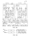
- FIGURE 5B there is a diagram showing exemplary frequency allocations for each of the antennas 202c' and 202c' ' in transceiver system 200c.
- RBSs RBS1, RBS2...RBSn
- RBS1 branch A can operate on one standard using TX1 while RBS1 branch B can operate on the same or another standard using TX4.
- RBS1 branch A and RBS1 branch B have RX diversity because both have the same RX band.
- RBS2 can work in the adjacent band with a different standard.
- transceiver system 200c has a lower insertion loss ( ⁇ 1dB) than transceiver system 200a. Because, the TX signals transmitted from the RBS2s pass through one filter 512 in the transceiver system 200c and pass through two TX filters 312 and 316 in the transceiver system 200a. Also, it should be noted that transceiver system 200c uses one diplex-duplex filter 502 while transceiver system 200a uses a diplex filter 302 and a separate duplex filter 304 per branch.
- transceiver system 200d and in particular each of the RBSs (RBS1, RBS2...RBSn) have two branches (branch A and branch B).
- branch A branch A of transceiver system 200d is described first and then a brief discussion is provided about branch B which has essentially the same filter unit as branch A.
- the transceiver system 200d includes an antenna 202d' which is coupled to a filter unit 204d' that in turn is coupled to branch A of multiple RBSs (RBS1, RBS2...RBSn).
- Each RBS (RBS1, RBS2...RBSn) uses a TX/RX cable 206d to connect to the filter unit 204d'.
- each RBS (RBS1, RBS2...RBSn) has a duplex filter 208d incorporated therein.
- the filter unit 204d' has a unique configuration which in this embodiment includes a diplex-duplex filter 602 and may have a low noise amplifier (LNA) 604 with a splitter function.
- LNA low noise amplifier
- a detailed discussion is provided next on how the filter unit 204d' is configured so as to enable the RBSs (RBS1, RBS2...RBSn) to share one antenna 202d' even if the RBSs (RBS1, RBS2...RBSn) share the same frequency band and/or even if the RBSs (RBS1, RBS2...RBSn) operate with different radio standards (e.g., TDMA, CDMA, WCDMA and GSM).
- the filter unit 204d' includes the diplex-duplex filter 602, the LNA 604 and a splitter function.
- the diplex-duplex filter 602 includes two full-band receiver (RX) filters 606 and 608 and two part-band transceiver (TX) filters 610 and 612.
- RX full-band receiver
- TX part-band transceiver
- the first full-band RX filter 606 is coupled by way of the LNA 604 to the first part-band TX1 filter 610.
- the second full-band RX filter 608 is coupled to the second part-band TX2 filter 612 but is not coupled to the antenna 202d'.
- the first RBS1 and in particular the duplex filter 208d incorporated therein uses a TX/RX cable 206d to connect to the LNA 604 and the first part-band TX1 filter 610 in the diplex-duplex filter 602.
- the first RBS1 also includes a low noise amplifier (LNA) 614.
- the LNA 604 can couple a RX signal received from the full-band RX filter 606 in diplex-duplex filter 602 to the RX filter 608 in diplex-duplex filter 602.
- the second RBS2 and in particular the duplex filter 208d incorporated therein uses a TX/RX cable 206d to connect to the second full-band RX filter 608 and second part-band TX2 filter 612 in the diplex-duplex filter 602.
- the second RBS2 also includes a LNA 614.
- RBS1 can receive a RX signal applied to the antenna 202d' by way of the LNA 604 and transmit a TX signal within a TX1 band using the antenna 202d'.
- RBS2 can receive a RX signal applied to the antenna 202d' by way of the LNA 604 and transmit a TX signal within a TX2 band using the antenna 202d'.
- the filter unit 204d' and in particular the diplex-duplex filter 602 would include another full-band receiver (RX) filter 618 (shown as RX filter 618) and another part-band transceiver (TX) filter 620 (shown as TX3 filter 620).
- RX full-band receiver
- TX part-band transceiver
- the full-band RX filter 618 is coupled to the LNA 604 and the part-band TX3 filter 620 but is not coupled to the antenna 202d'.
- the additional RBS (shown) and in particular the duplex filter 208d incorporated therein uses a TX/RX cable 206d to connect to the diplex-duplex filter 602.
- the RBSn also includes a LNA 614.
- RBSn can receive a RX signal applied to the antenna 202d' by way of the LNA 604 and transmit a TX signal within a TX3 band using the antenna 202d'.
- the same filter scheme associated with filter unit 204d' is used to make filter unit 204d" which is associated with branch B of the RBSs (RBS1, RBS2...RBSn) that share antenna 202d".
- FIGURE 6B there is a diagram showing exemplary frequency allocations for each of the antennas 202d' and 202d" in transceiver system 200d.
- RBSs RBS1, RBS2...RBSn
- RBS1 branch A can operate on one standard using TX1 while RBS1 branch B can operate on the same or another standard using TX4.
- RBS1 branch A and RBS1 branch B have RX diversity because both have the same RX band.
- RBS2 can work in the adjacent band with a different standard.
- transceiver system 200d does not have a coupler 516 and accompanying RX cable 207c in the RBS1 nor does it have the splitter 504 like shown in transceiver system 200c.
- the transceiver system 200d does have an additional active component LNA 604 outside of the RBSs.
- the transceiver system 200d and in particular the RBS1 has a slightly worse RX performance than the RBS1 in transceiver system 200c.
- TMA Tower mounted amplifier
- transceiver systems 200a, 200b, 200c and 200d are well known in the industry. Therefore, for clarity, the description provided above omitted those well known details and components of the transceiver systems 200a, 200b, 200c and 200d that are not necessary to understand the present invention.
- a diplex filter normally filters signals in one band (e.g., 1900 band) from another band (e.g., 800 band).
- a duplex filter filters a TX band from a RX band.
- FIGURE 7 there is a flowchart illustrating the steps of a preferred method 700 for constructing the transceiver system 700 shown in FIGURES 2, 3A, 4A, 5A and 6A in accordance with the present invention.
- one antenna 202 is provided for each branch of the RBSs used in the transceiver system 200.
- a filter configuration 204 is provided that has a unique combination of diplex filter(s), duplex filter(s), part-band duplex filter(s), diplex-duplex filter(s), splitter(s) and/or LNA(s) (see FIGURES 3A, 4A, 5A and 6A).
- each RBS has a duplex filter 208 incorporated therein.
- Each RBS (RBS1, RBS2...RBSn) and in particular each duplex filter 208 is coupled to the filter configuration 204 which is configured in a manner that enables all of the RBSs (RBS1, RBS2...RBSn) to share the antenna 202 even if the RBSs (RBS1, RBS2...RBSn) share a frequency band and even if the RBSs (RBS1, RBS2...RBSn) operate with different radio standards (e.g., TDMA, CDMA, WCDMA and GSM).
- TDMA Time Division Multiple Access
- CDMA Code Division Multiple Access
- WCDMA Wideband Code Division Multiple Access
Landscapes
- Engineering & Computer Science (AREA)
- Computer Networks & Wireless Communication (AREA)
- Signal Processing (AREA)
- Transceivers (AREA)
- Time-Division Multiplex Systems (AREA)
- Radar Systems Or Details Thereof (AREA)
- Mobile Radio Communication Systems (AREA)
- Radio Transmission System (AREA)
Claims (20)
- Senderemprzinger-System (200), umfassend:eine Antenne (202);eine Filtereinheit (204), gekoppelt an die Antenne und an eine Vielzahl von Funkbasisstationen (RBSI. RBS2,...,RBSN), dadurch gekennzeichnet, dass jede der Funkbasisstationen ein in sie eingebautes Duplexfilter (208) hat, deren alle an die Filtereinheit (204) gekoppelt sind, wobei die Filtereinheit dazu konfiguriert ist, den Funkbasisstationen zu ermöglichen, sich die Antenne zu teilen, sogar dann, wenn sich die Funkbasisstationen ein Frequenzband teilen und sogar dann, wenn die Funkbasisstationen mit verschiedenen Funkstandards arbeiten.
- Senderempfänger-System nach Anspruch 1, worin die Filtereinheit enthält:ein an die Antenne gekoppeltes Diplexfilter, wobei das Diplexfilter enthält:wobei die erste Funkbasisstation ein in sie eingebautes Duplexfilter hat, das an das Vollband-RX-Filter und das erste Teilband-TX-Filter im Diplexfilter gekoppelt ist;ein Vollbandempfänger(RX)-Filter: undzwei Teilband-Senderempfänger(TX)-Filter, wo das Vollband-RX-Filter an das erste Teilband-TX-Filter gekoppelt ist; und ein erstes Duplexfilter, das enthält:ein an das zweite Teilband-TX-Filter im Diplexfilter gekoppeltes TX-Filter; undein RX-Filter; und
wobei die erste Funkbasisstation auch mit einem Splitter verbunden ist, der ein vom Vollband-RX-Filter im Diplexfilter empfangenes RX-Signal an das RX-Filter im ersten Duplexfilter koppelt; und
wobei die zweite Funkbasisstation ein in sie eingebautes Duplexfilter hat, das an das TX-Filter und das RX-Filter im ersten Duplexfilter gekoppelt ist. - Senderempfänger-System nach Anspruch 2, außerdem umfassend, dass das Diplexfilter außerdem enthält:ein drittes Teilband-Senderempfanger(TX)-Filter: undein zweites Duplexfilter, das enthält:ein TX-Filter, gekoppelt an das dritte Teilband-TX-Filter im Diplexfilter; undein RX-Filter: unddie dritte Funkbasisstation mit einem in sie eingebauten Duplexfilter, gekoppelt an das TX-Filter und das RX-Filter im zweiten Duplexfilter, das das RX-Filter hat, das vom Splitter das RX-Signal empfängt.
- Senderempfänger-System nach Anspruch 1, worin die Filtereinheit enthält:ein an die Antenne gekoppeltes Teilband-Duplexfilter, wobei das Teilband-Duplexfilter enthält:wobei die erste Funkbasisstation ein in sie eingebautes Duplexfilter hat, das an das erste Teilband-RX-Filter und das erste Teilband-TX-Filter im Teilband-Duplexfilter gekoppelt ist: undzwei Teilbandempfänger(RX)-Filter: undzwei Teilband-Senderempfänger(TX)-Filter, wo das erste Teilband-RX-Filter an das erste Teilband-TX-Filter gekoppelt ist und wo das zweite Teilband-RX-Filter an das zweite Teilband-TX-Filter gekoppelt ist; und
wobei die zweite Funkbasisstation ein in sie eingebautes Duplexfilter hat, das an das zweite Teilband-RX-Filter und das zweite Teilband-TX-Filter im Teilband-Duplexfilter gekoppelt ist. - Senderempfänger-System nach Anspruch 4, außerdem umfassend:dass das Teilband-Duplexfilter außerdem enthält:wobei die dritte Funkbasisstation ein in sie eingebautes Duplexfilter hat, das an das dritte Teilband-RIX-Filter und das dritte Teilband-TX-Filter im Teilband-Duplexfilter gekoppelt ist.ein drittes Teilbandempfänger(RX)-Filter; undein drittes Teilband-Senderempfänger(TX)-Filter, wo das dritte Teilband-RX-Filter an das dritte Teilband-TX-Filter gekoppelt ist: und
- Senderempfänger-System nach Anspruch 1, worin die Filtereinheit enthält:ein an die Antenne gekoppeltes Diplex-Duplexfilter, wobei das Diplex-Duplexfilter enthält:wobei die erste Funkbasisstation ein in sie eingebautes Duplexfilter hat, das an das erste Vollband-RX-Filter und das erste Teilband-TX-Filter im Diplex-Duplexfilter gekoppelt ist;zwei Vollbandempfänger(RX)-Filter: undzwei Teilband-Senderempfänger(TX)-Filter, wo das erste Vollband-RX-Filter an das erste Teilband-TX-Filter gekoppelt ist und wo das zweite Vollband-RX-Filter an das zweite Teilband-TX-Filter gekoppelt ist: und
wobei die erste Funkbasisstation auch mit einem Splitter verbunden ist, der ein vom ersten Vollband-RX-Filter empfangenes RX-Signal an das zweite Vollband-RX-Filter im Diplex-Duplexfilter koppelt, worin das zweite Vollband-RX-Filter nicht mit der Antenne verbunden ist; und
wobei die zweite Funkbasisstation ein in sie eingebautes Duplexfilter hat, das an das zweite Vollband-RX-Filter und das zweite Teilband-TX-Filter im Diplex-Duplexfilter gekoppelt ist. - Senderempfänger-System nach Anspruch 6, außerdem umfassend, dass das Diplex-Duplexfilter außerdem enthält:ein drittes Vollbandempfänger(RX)-Filter: undein drittes Teilband-Senderempfänger(TX)-Filter, wo das dritte Vollband-RX-Filter an das dritte Teilband-TX-Filter gekoppelt ist; undwobei die dritte Funkbasisstation ein in sie eingebautes Duplexfilter hat, das an das dritte Vollband-RX-Filter und das dritte Teilband-TX-Filter im Diplex-Duplexfilter gekoppelt ist, worin das dritte Vollband-RX-Filter nicht mit der Antenne verbunden ist, sondern stattdessen das RX-Signal vom Splitter empfängt.
- Senderempfänger-System nach Anspruch 1, worin die Filtereinheit enthält:ein an die Antenne gekoppeltes Diplex-Duplexfilter, wobei das Diplex-Duplexfilter enthält:wobei die erste Funkbasisstation ein in sie eingebautes Duplexfilter hat, das durch einen geräuscharmen Verstärker an das erste Vollband-RX-Filter gekoppelt ist und auch an das erste Teilband-TX-Filter im Diplex-Duplexfilter gekoppelt ist;zwei Vollbandempfänger(RX)-Filter; undzwei Teilband-Senderempfänger(TX)-Filter, wo das zweite Vollband-RX-Filter an das zweite Teilband-TX-Filter gekoppelt ist; und
wobei der geräuscharme Verstärker auch ein vom ersten Vollband-RX-Filter empfangenes RX-Signal an das zweite Vollband-RX-Filter im Diplex-Duplexfilter koppelt, worin das zweite Vollband-RX-Filter nicht mit der Antenne verbunden ist: und
wobei die zweite Funkbasisstation ein in sie eingebautes Duplexfilter hat, das an das zweite Vollband-RX-Filter und das zweite Teilband-TX-Filter im Diplex-Duplexfilter gekoppelt ist. - Senderempfänger-System nach Anspruch 8. außerdem umfassend, dass das Diplex-Duplexfilter außerdem enthält:ein drittes Vollbandempfanger(RX)-Filter: undein drittes Teilband-Senderempfänger(TX)-Filter, wo das dritte Vollband-RX-Filter an das dritte Teilband-TX-Filter gekoppelt ist; undwobei die dritte Funkbasisstation ein in sie eingebautes Duplexfilter hat, das an das dritte Vollband-RX-Filter und das dritte Teilband-TX-Filter im Diplex-Duplexfilter gekoppelt ist, worin das dritte Vollband-RX-Filter nicht mit der Antenne verbunden ist, sondern stattdessen das RX-Signal vom geräuscharmen Verstärker empfängt.
- Senderempfänger-System nach Anspruch 1, worin die Funkstandards enthalten:Zeitvielfachzugriff (TDMA):Codemultiplex-Vielfachzugriff (CDMA);Breitband-CDMA (W-CDMA); unddas Globalsystem für Mobilkommunikation (GSM).
- Verfahren zum Konstruieren eines Senderempfänger-Systems, folgende Schritte umfassend:Bereitstellen einer Antenne (202);Bereitstellen einer an die Antenne gekoppelten Filtereinheit (204); undBereitstellen von mindestens zwei Funkbasisstationen (RBS1, RBS2.....RBSN), dadurch gekennzeichnet, dass jede der Funkbasisstationen ein in sie eingebautes Duplexfilter hat, deren alle an die Filtereinheit gekoppelt sind, wobei die Filtereinheit dazu konfiguriert ist, den Funkbasisstationen zu ermöglichen, sich die Antenne zu teilen, sogar dann, wenn sich die Funkbasisstationen ein Frequenzband teilen und sogar dann, wenn die Funkbasisstationen mit verschiedenen Funkstandards arbeiten.
- Verfahren nach Anspruch 11, worin die Filtereinheit enthält:ein an die Antenne gekoppeltes Diplexfilter, wobei das Diplexfilter enthält:wobei die erste Funkbasisstation das in sie eingebaute Duplexfilter enthält, das an das Vollband-RX-Filter und das erste Teilband-TX-Filter im Diplexfilter gekoppelt ist;ein Vollbandempfänger(RX)-Filter; undzwei Teilband-Senderempfänger(TX)-Filter, wo das Vollband-RX-Filter an das erste Teilband-TX-Filter gekoppelt ist: und ein erstes Duplexfilter, das enthält:ein TX-Filter, das an das zweite Teilband-TX-Filter im Diplexfilter gekoppelt ist; undein RX-Filter; und
wobei die erste Funkbasisstation auch mit einem Splitter verbunden ist, der ein vom Vollband-RX-Filter im Diplexfilter empfangenes RX-Signal an das RX-Filter im ersten Duplexfilter koppelt; und
wobei die zweite Funkbasisstation das in sie eingebaute Duplexfilter enthält, das an das TX-Filter und das RX-Filter im ersten Duplexfilter gekoppelt ist. - Verfahren nach Anspruch 12, worin der Schritt des Bereitstellens von mindestens zwei Funkbasisstationen das Hinzufügen einer neuen Funkbasisstation zu den mindestens zwei Funkbasisstationen enthält, in welchem Fall das Diplexfilter außerdem enthält:ein drittes Teilband-Senderempfänger(TX)-Filter; undein zweites Duplexfilter, das enthält:wobei die neue Funkbasisstation ein in sie eingebautes Duplexfilter enthält, gekoppelt an das TX-Filter und das RX-Filter im zweiten Duplexfilter, das das RX-Filter hat, das vom Splitter das RX-Signal empfängt.ein TX-Filter, das an das dritte Teilband-TX-Filter im Diplexfilter gekoppelt ist; undein RX-Filter; und
- Verfahren nach Anspruch 11, worin die Filtereinheit enthält:ein an die Antenne gekoppeltes Teilband-Duplexfilter, wobei das Teilband-Duplexfilter enthält:wobei die erste Funkbasisstation das in sie eingebaute Duplexfilter enthält, das an das erste Teilband-RX-Filter und das erste Teilband-TX-Filter im Teilband-Duplexfilter gekoppelt ist; undzwei Teilbandempfänger(RX)-Filter; undzwei Teilband-Senderempfänger(TX)-Filter, wo das erste Teilband-RX-Filter an das erste Teilband-TX-Filter gekoppelt ist und wo das zweite Teilband-RX-Filter an das zweite Teilband-TX-Filter gekoppelt ist; und
wobei die zweite Funkbasisstation das in sie eingebaute Duplexfilter enthält, das an das zweite Teilband-RX-Filter und das zweite Teilband-TX-Filter im Teilband-Duplexfilter gekoppelt ist. - Verfahren nach Anspruch 14, worin der Schritt des Bereitstellens von mindestens zwei Funkbasisstationen das Hinzufügen einer neuen Funkbasisstation zu den mindestens zwei Funkbasisstationen enthält, in welchem Fall das Teilband-Duplexfilter außerdem enthält:ein drittes Teilbandeimpfänger(RX)-Filter; undein drittes Teilband-Senderempfänger(TX)-Filter, wo das dritte Teilband-RX-Filter an das dritte Teilband-TX-Filter gekoppelt ist; undwobei die neue Funkbasisstation ein in sie eingebautes Duplexfilter enthält, das an das dritte Teilband-RX-Filter und das dritte Teilband-TX-Filter im Teilband-Duplexfilter gekoppelt ist.
- Verfahren nach Anspruch 11, worin die Filtereinheit enthält:ein an die Antenne gekoppeltes Diplex-Duplexfilter, wobei das Diplex-Duplexfilter enthält:wobei die erste Funkbasisstation das in sie eingebaute Duplexfilter enthält, das an das erste Vollband-RX-Filter und das erste Teilband-TX-Filter im Diplex-Duplexfilter gekoppelt ist;zwei Vollbandempfänger(RX)-Filter; undzwei Teilband-Senderempfänger(TX)-Filter, wo das erste Vollband-RX-Filter an das erste Teilband-TX-Filter gekoppelt ist und wo das zweite Vollband-RX-Filter an das zweite Teilband-TX-Filter gekoppelt ist; und
wobei die erste Funkbasisstation auch mit einem Splitter verbunden ist, der ein vom ersten Vollband-RX-Filter empfangenes RX-Signal an das zweite Vollband-RX-Filter im Diplex-Duplexfilter koppelt, worin das zweite Vollband-RX-Filter nicht mit der Antenne verbunden ist; und
wobei die zweite Funkbasisstation das in sie eingebaute Duplexfilter enthält, das an das zweite Vollband-RX-Filter und das zweite Teilband-TX-Filter im Diplex-Duplexfilter gekoppelt ist. - Verfahren nach Anspruch 16, worin der Schritt des Bereitstellens von mindestens zwei Funkbasisstationen das Hinzufügen einer neuen Funkbasisstation zu den mindestens zwei Funkbasisstationen enthält, in welchem Fall das Diplex-Duplexfilter außerdem enthält:ein drittes Vollbandempfänger(RX)-Filter: undein drittes Teilband-Senderempfänger(TX)-Filter, wo das dritte Vollband-RX-Filter an das dritte Teilband-TX-Filter gekoppelt ist; undwobei die neue Funkbasisstation ein in sie eingebautes Duplexfilter enthält, das an das dritte Vollband-RX-Filter und das dritte Teilband-TX-Filter im Diplex-Duplexfilter gekoppelt ist, worin das dritte Vollband-RX-Filter nicht mit der Antenne verbunden ist, sondern stattdessen das RX-Signal vom Splitter empfängt.
- Verfahren nach Anspruch 11, worin die Filtereinheit enthält:ein an die Antenne gekoppeltes Diplex-Duplexfilter, wobei das Diplex-Duplexfilter enthält:wobei die erste Funkbasisstation das in sie eingebaute Duplexfilter enthält, das durch einen geräuscharmen Verstärker an das erste Vollband-RX-Filter gekoppelt ist und auch an das erste Teilband-TX-Filter im Diplex-Duplexfilter gekoppelt ist;zwei Vollbandempfänger(RX)-Filter; undzwei Teilband-Senderempfänger(TX)-Filter, wo das zweite Vollband-RX-Filter an das zweite Teilband-TX-Filter gekoppelt ist: und
wobei der geräuscharme Verstärker auch ein vom ersten Vollband-RX-Filter empfangenes RX-Signal an das zweite Vollband-RX-Filter im Diplex-Duplexfilter koppelt, worin das zweite Vollband-RX-Filter nicht mit der Antenne verbunden ist: und
wobei die zweite Funkbasisstation das in sie eingebaute Duplexfilter enthält, das an das zweite Vollband-RX-Filter und das zweite Teilband-TX-Filter im Diplex-Duplexfilter gekoppelt ist. - Verfahren nach Anspruch 18, worin der Schritt des Bereitstellens von mindestens zwei Funkbasisstationen das Hinzufügen einer neuen Funkbasisstation zu den mindestens zwei Funkbasisstationen enthält, in welchem Fall das Diplex-Duplexfilter außerdem enthält:ein drittes Vollbandempfänger(RX)-Filter: undein drittes Teilband-Senderempfänger(TX)-Filter, wo das dritte Vollband-RX-Filter an das dritte Teilband-TX-Filter gekoppelt ist; undwobei die dritte Funkbasisstation ein in sie eingebautes Duplexfilter enthält, das an das dritte Vollband-RX-Filter und das dritte Teilband-TX-Filter im Diplex-Duplexfilter gekoppelt ist, worin das dritte Vollband-RX-Filter nicht mit der Antenne verbunden ist, sondern stattdessen das RX-Signal vom geräuscharmen Verstärker empfängt.
- Verfahren nach Anspruch 11. worin die Funkstandards enthalten:Zeitvielfachzugriff (TDMA):Codemultiplex-Vielfachzugriff (CDMA):Breitband-CDMA (W-CDMA); unddas Globalsystem für Mobilkommunikation (GSM).
Priority Applications (1)
| Application Number | Priority Date | Filing Date | Title |
|---|---|---|---|
| PL04800333T PL1695449T3 (pl) | 2003-12-20 | 2004-11-15 | System nadawczo-odbiorczy zawierający wiele radiostacji bazowych współużytkujących antenę |
Applications Claiming Priority (2)
| Application Number | Priority Date | Filing Date | Title |
|---|---|---|---|
| US10/743,555 US7120465B2 (en) | 2003-12-20 | 2003-12-20 | Transceiver system including multiple radio base stations that share an antenna |
| PCT/SE2004/001670 WO2005062476A1 (en) | 2003-12-20 | 2004-11-15 | Transceiver system including multiple radio base stations that share an antenna |
Publications (2)
| Publication Number | Publication Date |
|---|---|
| EP1695449A1 EP1695449A1 (de) | 2006-08-30 |
| EP1695449B1 true EP1695449B1 (de) | 2008-01-23 |
Family
ID=34678673
Family Applications (1)
| Application Number | Title | Priority Date | Filing Date |
|---|---|---|---|
| EP04800333A Expired - Lifetime EP1695449B1 (de) | 2003-12-20 | 2004-11-15 | Sender/empfänger-system mit mehreren funkbasisstationen, die sich eine antenne teilen |
Country Status (8)
| Country | Link |
|---|---|
| US (1) | US7120465B2 (de) |
| EP (1) | EP1695449B1 (de) |
| JP (1) | JP4602990B2 (de) |
| CN (1) | CN1898878B (de) |
| AT (1) | ATE385074T1 (de) |
| DE (1) | DE602004011561T2 (de) |
| PL (1) | PL1695449T3 (de) |
| WO (1) | WO2005062476A1 (de) |
Families Citing this family (30)
| Publication number | Priority date | Publication date | Assignee | Title |
|---|---|---|---|---|
| KR100485516B1 (ko) * | 2002-04-22 | 2005-04-27 | 주식회사 케이티프리텔 | 이동 통신망의 기지국 및 그 기지국에서 신호 수신 및처리 방법 |
| US8412117B2 (en) | 2005-06-17 | 2013-04-02 | Telefonaktiebolaget L M Ericsson (Publ) | Method and arrangement for improved feeder sharing in a telecommunication system |
| CN100372407C (zh) * | 2005-09-16 | 2008-02-27 | 华为技术有限公司 | 一种wcdma与同频段gsm系统共天线的实现方法及系统 |
| TWI305979B (en) * | 2006-03-24 | 2009-02-01 | Hon Hai Prec Ind Co Ltd | Wireless transceiving system |
| EP1999856B1 (de) * | 2006-03-28 | 2015-08-26 | Telefonaktiebolaget L M Ericsson (publ) | Funkbasisstationssystem, knoten in einem zellularen mobilkommunikationsnetz und teilereinrichtung |
| CN101427604A (zh) * | 2006-05-18 | 2009-05-06 | Ut斯达康(中国)有限公司 | PHS和WiMAX双模式基站 |
| TWI355840B (en) * | 2006-12-07 | 2012-01-01 | Wistron Neweb Corp | Communication device capable of simultaneously ope |
| GB2444980B (en) * | 2006-12-22 | 2012-02-22 | Deltenna Ltd | Antenna system |
| GB2483826B (en) * | 2006-12-22 | 2012-05-30 | Deltenna Ltd | Antenna system |
| EP2122744B1 (de) * | 2007-02-19 | 2016-05-04 | Telefonaktiebolaget LM Ericsson (publ) | Vorrichtung und verfahren zum lenken eines empfangssignals in einem antennensystem |
| CN100579265C (zh) * | 2007-03-30 | 2010-01-06 | 华为技术有限公司 | 共用射频前端、基站和射频前端共用的方法 |
| US9002364B2 (en) * | 2007-05-22 | 2015-04-07 | Tango Networks, Inc. | System, method, and computer-readable medium for concurrent termination of multiple calls at a mobile terminal |
| US7701887B2 (en) * | 2007-11-21 | 2010-04-20 | Adc Telecommunications, Inc. | Multiplexing apparatus in a transceiver system |
| WO2009079701A1 (en) * | 2007-12-20 | 2009-07-02 | Triasx Pty Ltd | Signal combiner |
| US8315670B2 (en) * | 2008-01-08 | 2012-11-20 | Alcatel Lucent | Base station antenna interface system for antenna cable reduction in dual band deployments |
| JP5157550B2 (ja) * | 2008-03-17 | 2013-03-06 | 日本電気株式会社 | 信号分配装置、無線装置及び通信システム |
| WO2010124410A1 (zh) * | 2009-04-28 | 2010-11-04 | 阿尔卡特朗讯 | 在不同无线通信系统之间共享天线的方法和设备 |
| EP2426970A4 (de) * | 2009-05-11 | 2012-08-01 | Huawei Tech Co Ltd | Verfahren zum teilen einer hf-empfangseinheit, vorrichtung und system dafür |
| CN101777932A (zh) * | 2009-12-23 | 2010-07-14 | 华为技术有限公司 | 天线振子复用的方法、装置和天线组件 |
| EP2375498B1 (de) * | 2010-04-09 | 2016-01-27 | Alcatel Lucent | System und Verfahren zur Bereitstellung unabhängiger Polarisationssteuerung |
| GB201009846D0 (en) * | 2010-06-14 | 2010-07-21 | Radio Design Ltd | Combiner |
| JP5429077B2 (ja) * | 2010-06-28 | 2014-02-26 | 富士通株式会社 | 移動通信システム、基地局及び通信制御方法 |
| US9559729B2 (en) | 2011-03-30 | 2017-01-31 | Alcatel Lucent | Same-band combiner using dual-bandpass channel filters |
| EP2552173A1 (de) * | 2011-07-29 | 2013-01-30 | Vodafone Holding GmbH | Mobilkommunikationsverfahren und System umfassend gemeinsame Netzwerk- und Antennenbenutzung und hierarchische Sektorisierung |
| WO2015018057A1 (zh) * | 2013-08-09 | 2015-02-12 | 华为技术有限公司 | 多运营商共享天线的方法、系统和射频数字转换单元 |
| CN105164945B (zh) * | 2013-11-27 | 2017-11-28 | 华为技术有限公司 | 同频段合分路器和多系统合路平台 |
| WO2017113304A1 (zh) | 2015-12-31 | 2017-07-06 | 华为技术有限公司 | 无线终端及无线终端的天线切换控制方法 |
| KR20190095413A (ko) | 2016-12-28 | 2019-08-14 | 후아웨이 테크놀러지 컴퍼니 리미티드 | 브랜칭 타워-탑재 증폭기 및 안테나 급전 시스템 |
| CN112929037B (zh) * | 2021-01-29 | 2022-04-01 | 中国铁塔股份有限公司 | 信号合路系统及电子设备 |
| US12334959B2 (en) | 2021-04-08 | 2025-06-17 | Skyworks Solutions, Inc. | Apparatus and methods for diplexing by antenna structure |
Family Cites Families (18)
| Publication number | Priority date | Publication date | Assignee | Title |
|---|---|---|---|---|
| US52272A (en) * | 1866-01-30 | Improvement in churns | ||
| FI88660C (fi) | 1991-01-09 | 1993-06-10 | Nokia Telecommunications Oy | Radiosaendarmottagarsystem |
| GB2281663B (en) | 1993-08-18 | 1997-08-20 | Nokia Telecommunications Oy | Filters for radio base stations |
| JPH09238090A (ja) * | 1996-02-29 | 1997-09-09 | Fujitsu Ltd | 併設無線システム |
| US5781865A (en) | 1996-05-20 | 1998-07-14 | Scientific Research Corporation | PCS cell site system for allowing a plurality of PCS providers to share cell site antennas |
| US5768691A (en) * | 1996-08-07 | 1998-06-16 | Nokia Mobile Phones Limited | Antenna switching circuits for radio telephones |
| US6070090A (en) * | 1997-11-13 | 2000-05-30 | Metawave Communications Corporation | Input specific independent sector mapping |
| EP1096818A1 (de) * | 1999-10-29 | 2001-05-02 | TELEFONAKTIEBOLAGET LM ERICSSON (publ) | Basisstation mit einer ersten und zweiten Basiseinheit |
| US6792289B1 (en) * | 1999-11-08 | 2004-09-14 | Qualcomm Incorporated | Non-bandlimiting antenna sharing method and apparatus for base stations |
| CA2327761A1 (en) * | 1999-12-21 | 2001-06-21 | Lucent Technologies Inc. | Wireless systems combining arrangement and method thereof |
| US6658263B1 (en) * | 1999-12-21 | 2003-12-02 | Lucent Technologies Inc. | Wireless system combining arrangement and method thereof |
| US6804540B1 (en) * | 2000-08-02 | 2004-10-12 | Ericsson Inc. | Remote band-pass filter in a distributed antenna system |
| US6985712B2 (en) * | 2001-08-27 | 2006-01-10 | Matsushita Electric Industrial Co., Ltd. | RF device and communication apparatus using the same |
| US6925312B2 (en) * | 2001-09-17 | 2005-08-02 | Telefonaktiebolaget Lm Ericsson (Publ) | Sharing of antennas by base station nodes of telecommunications network |
| US6895247B2 (en) * | 2001-11-01 | 2005-05-17 | Ericsson, Inc. | System and method for obtaining optimum RF performance when co-siting cellular base stations |
| ES2192970B1 (es) | 2001-12-14 | 2005-09-01 | Dyctel Infraestructuras De Telecomunicaciones, S.A. | Antena inteligente compatible modular multiestandar para comunicaciones celulares en entornos multioperador. |
| US6774857B2 (en) | 2002-09-12 | 2004-08-10 | Agilent Technologies, Inc. | Method facilitating inter-mode handoff |
| JP2004222171A (ja) * | 2003-01-17 | 2004-08-05 | Matsushita Electric Ind Co Ltd | マルチモード通信装置及び帯域制限フィルタ制御方法 |
-
2003
- 2003-12-20 US US10/743,555 patent/US7120465B2/en not_active Expired - Lifetime
-
2004
- 2004-11-15 WO PCT/SE2004/001670 patent/WO2005062476A1/en not_active Ceased
- 2004-11-15 JP JP2006545275A patent/JP4602990B2/ja not_active Expired - Fee Related
- 2004-11-15 DE DE602004011561T patent/DE602004011561T2/de not_active Expired - Lifetime
- 2004-11-15 AT AT04800333T patent/ATE385074T1/de not_active IP Right Cessation
- 2004-11-15 CN CN2004800381258A patent/CN1898878B/zh not_active Expired - Fee Related
- 2004-11-15 PL PL04800333T patent/PL1695449T3/pl unknown
- 2004-11-15 EP EP04800333A patent/EP1695449B1/de not_active Expired - Lifetime
Also Published As
| Publication number | Publication date |
|---|---|
| WO2005062476A1 (en) | 2005-07-07 |
| CN1898878A (zh) | 2007-01-17 |
| CN1898878B (zh) | 2010-10-27 |
| US7120465B2 (en) | 2006-10-10 |
| JP2007515895A (ja) | 2007-06-14 |
| ATE385074T1 (de) | 2008-02-15 |
| EP1695449A1 (de) | 2006-08-30 |
| US20050136875A1 (en) | 2005-06-23 |
| PL1695449T3 (pl) | 2008-06-30 |
| DE602004011561T2 (de) | 2009-02-05 |
| DE602004011561D1 (de) | 2008-03-13 |
| JP4602990B2 (ja) | 2010-12-22 |
Similar Documents
| Publication | Publication Date | Title |
|---|---|---|
| CN1898878B (zh) | 包括共用天线的多个无线电基站的收发信机系统 | |
| US7450853B2 (en) | Signal transmission apparatus and method for optical base station | |
| US9356697B2 (en) | Distributed antenna system and method | |
| EP1026908B1 (de) | Als Zweiwegradio arbeitendes Dual-Mode-Mobiltelefon und entsprechendes Verfahren | |
| EP0511341B1 (de) | Funksendeempfänger | |
| US9306669B2 (en) | Optic distributed antenna system supporting multi-band multi-carrier service over a reduced number of optic core lines | |
| US8971220B2 (en) | Dual mode base station | |
| CA2562053A1 (en) | Multi-antenna transceiver system | |
| EP2640028B1 (de) | Verfahren, vorrichtung und system zur übertragung von kommunikationssignalen | |
| KR20040066179A (ko) | 연속모드 송수신기를 구비한 다중 모드 이동 통신 디바이스 및 그 방법 | |
| CN111800160A (zh) | 一种电子设备 | |
| EP0715786B1 (de) | Basisstationsanlage unter verwendung von diversityempfang | |
| CN110504984A (zh) | 一种电子设备 | |
| CN110800160A (zh) | 天线系统、基站以及通信系统 | |
| EP2122744B1 (de) | Vorrichtung und verfahren zum lenken eines empfangssignals in einem antennensystem | |
| EP1243147B1 (de) | Basisstation mit einer ersten und zweiten basiseinheit | |
| EP2101541A1 (de) | Funkkopf für Straßen oder ländliche Umgebungen | |
| CN105450250B (zh) | 滤波装置、控制方法和电子设备 | |
| KR20010060268A (ko) | 전자기 신호용 송신/수신 장치, 송신/수신 셀, 송신/수신국 및 주파수 호핑 방법 | |
| EP2777092B1 (de) | Kombinierte vorrichtung zur verwendung in einer vorrichtung zum senden und/oder empfangen von signalen | |
| KR200253529Y1 (ko) | 다이버시티 안테나를 이용한 송신출력 분기형 중계장치 | |
| CN118316473A (zh) | 一种射频收发器通道连接电路和电路板 | |
| GB2387995A (en) | Multi-mode portable telecommunication terminal with Dielectric Resonator Antenna |
Legal Events
| Date | Code | Title | Description |
|---|---|---|---|
| PUAI | Public reference made under article 153(3) epc to a published international application that has entered the european phase |
Free format text: ORIGINAL CODE: 0009012 |
|
| 17P | Request for examination filed |
Effective date: 20060505 |
|
| AK | Designated contracting states |
Kind code of ref document: A1 Designated state(s): AT BE BG CH CY CZ DE DK EE ES FI FR GB GR HU IE IS IT LI LU MC NL PL PT RO SE SI SK TR |
|
| DAX | Request for extension of the european patent (deleted) | ||
| 17Q | First examination report despatched |
Effective date: 20070507 |
|
| GRAP | Despatch of communication of intention to grant a patent |
Free format text: ORIGINAL CODE: EPIDOSNIGR1 |
|
| RIN1 | Information on inventor provided before grant (corrected) |
Inventor name: SKAERBY, ULF Inventor name: LINDELL, PATRIK |
|
| RAP1 | Party data changed (applicant data changed or rights of an application transferred) |
Owner name: TELEFONAKTIEBOLAGET LM ERICSSON (PUBL) |
|
| GRAS | Grant fee paid |
Free format text: ORIGINAL CODE: EPIDOSNIGR3 |
|
| GRAA | (expected) grant |
Free format text: ORIGINAL CODE: 0009210 |
|
| AK | Designated contracting states |
Kind code of ref document: B1 Designated state(s): AT BE BG CH CY CZ DE DK EE ES FI FR GB GR HU IE IS IT LI LU MC NL PL PT RO SE SI SK TR |
|
| REG | Reference to a national code |
Ref country code: GB Ref legal event code: FG4D |
|
| REG | Reference to a national code |
Ref country code: CH Ref legal event code: EP |
|
| REG | Reference to a national code |
Ref country code: IE Ref legal event code: FG4D |
|
| REF | Corresponds to: |
Ref document number: 602004011561 Country of ref document: DE Date of ref document: 20080313 Kind code of ref document: P |
|
| REG | Reference to a national code |
Ref country code: PL Ref legal event code: T3 |
|
| NLV1 | Nl: lapsed or annulled due to failure to fulfill the requirements of art. 29p and 29m of the patents act | ||
| PG25 | Lapsed in a contracting state [announced via postgrant information from national office to epo] |
Ref country code: ES Free format text: LAPSE BECAUSE OF FAILURE TO SUBMIT A TRANSLATION OF THE DESCRIPTION OR TO PAY THE FEE WITHIN THE PRESCRIBED TIME-LIMIT Effective date: 20080504 Ref country code: IS Free format text: LAPSE BECAUSE OF FAILURE TO SUBMIT A TRANSLATION OF THE DESCRIPTION OR TO PAY THE FEE WITHIN THE PRESCRIBED TIME-LIMIT Effective date: 20080523 Ref country code: FI Free format text: LAPSE BECAUSE OF FAILURE TO SUBMIT A TRANSLATION OF THE DESCRIPTION OR TO PAY THE FEE WITHIN THE PRESCRIBED TIME-LIMIT Effective date: 20080123 Ref country code: CH Free format text: LAPSE BECAUSE OF FAILURE TO SUBMIT A TRANSLATION OF THE DESCRIPTION OR TO PAY THE FEE WITHIN THE PRESCRIBED TIME-LIMIT Effective date: 20080123 Ref country code: LI Free format text: LAPSE BECAUSE OF FAILURE TO SUBMIT A TRANSLATION OF THE DESCRIPTION OR TO PAY THE FEE WITHIN THE PRESCRIBED TIME-LIMIT Effective date: 20080123 |
|
| REG | Reference to a national code |
Ref country code: CH Ref legal event code: PL |
|
| PG25 | Lapsed in a contracting state [announced via postgrant information from national office to epo] |
Ref country code: AT Free format text: LAPSE BECAUSE OF FAILURE TO SUBMIT A TRANSLATION OF THE DESCRIPTION OR TO PAY THE FEE WITHIN THE PRESCRIBED TIME-LIMIT Effective date: 20080123 Ref country code: BG Free format text: LAPSE BECAUSE OF FAILURE TO SUBMIT A TRANSLATION OF THE DESCRIPTION OR TO PAY THE FEE WITHIN THE PRESCRIBED TIME-LIMIT Effective date: 20080423 |
|
| ET | Fr: translation filed | ||
| PG25 | Lapsed in a contracting state [announced via postgrant information from national office to epo] |
Ref country code: SI Free format text: LAPSE BECAUSE OF FAILURE TO SUBMIT A TRANSLATION OF THE DESCRIPTION OR TO PAY THE FEE WITHIN THE PRESCRIBED TIME-LIMIT Effective date: 20080123 Ref country code: PT Free format text: LAPSE BECAUSE OF FAILURE TO SUBMIT A TRANSLATION OF THE DESCRIPTION OR TO PAY THE FEE WITHIN THE PRESCRIBED TIME-LIMIT Effective date: 20080623 Ref country code: BE Free format text: LAPSE BECAUSE OF FAILURE TO SUBMIT A TRANSLATION OF THE DESCRIPTION OR TO PAY THE FEE WITHIN THE PRESCRIBED TIME-LIMIT Effective date: 20080123 |
|
| PG25 | Lapsed in a contracting state [announced via postgrant information from national office to epo] |
Ref country code: SK Free format text: LAPSE BECAUSE OF FAILURE TO SUBMIT A TRANSLATION OF THE DESCRIPTION OR TO PAY THE FEE WITHIN THE PRESCRIBED TIME-LIMIT Effective date: 20080123 Ref country code: SE Free format text: LAPSE BECAUSE OF FAILURE TO SUBMIT A TRANSLATION OF THE DESCRIPTION OR TO PAY THE FEE WITHIN THE PRESCRIBED TIME-LIMIT Effective date: 20080423 Ref country code: NL Free format text: LAPSE BECAUSE OF FAILURE TO SUBMIT A TRANSLATION OF THE DESCRIPTION OR TO PAY THE FEE WITHIN THE PRESCRIBED TIME-LIMIT Effective date: 20080123 Ref country code: DK Free format text: LAPSE BECAUSE OF FAILURE TO SUBMIT A TRANSLATION OF THE DESCRIPTION OR TO PAY THE FEE WITHIN THE PRESCRIBED TIME-LIMIT Effective date: 20080123 Ref country code: CZ Free format text: LAPSE BECAUSE OF FAILURE TO SUBMIT A TRANSLATION OF THE DESCRIPTION OR TO PAY THE FEE WITHIN THE PRESCRIBED TIME-LIMIT Effective date: 20080123 |
|
| PG25 | Lapsed in a contracting state [announced via postgrant information from national office to epo] |
Ref country code: RO Free format text: LAPSE BECAUSE OF FAILURE TO SUBMIT A TRANSLATION OF THE DESCRIPTION OR TO PAY THE FEE WITHIN THE PRESCRIBED TIME-LIMIT Effective date: 20080123 |
|
| PLBE | No opposition filed within time limit |
Free format text: ORIGINAL CODE: 0009261 |
|
| STAA | Information on the status of an ep patent application or granted ep patent |
Free format text: STATUS: NO OPPOSITION FILED WITHIN TIME LIMIT |
|
| 26N | No opposition filed |
Effective date: 20081024 |
|
| PG25 | Lapsed in a contracting state [announced via postgrant information from national office to epo] |
Ref country code: EE Free format text: LAPSE BECAUSE OF FAILURE TO SUBMIT A TRANSLATION OF THE DESCRIPTION OR TO PAY THE FEE WITHIN THE PRESCRIBED TIME-LIMIT Effective date: 20080123 |
|
| PG25 | Lapsed in a contracting state [announced via postgrant information from national office to epo] |
Ref country code: MC Free format text: LAPSE BECAUSE OF NON-PAYMENT OF DUE FEES Effective date: 20081130 |
|
| PG25 | Lapsed in a contracting state [announced via postgrant information from national office to epo] |
Ref country code: CY Free format text: LAPSE BECAUSE OF FAILURE TO SUBMIT A TRANSLATION OF THE DESCRIPTION OR TO PAY THE FEE WITHIN THE PRESCRIBED TIME-LIMIT Effective date: 20080123 |
|
| PG25 | Lapsed in a contracting state [announced via postgrant information from national office to epo] |
Ref country code: IE Free format text: LAPSE BECAUSE OF NON-PAYMENT OF DUE FEES Effective date: 20081117 |
|
| PG25 | Lapsed in a contracting state [announced via postgrant information from national office to epo] |
Ref country code: HU Free format text: LAPSE BECAUSE OF FAILURE TO SUBMIT A TRANSLATION OF THE DESCRIPTION OR TO PAY THE FEE WITHIN THE PRESCRIBED TIME-LIMIT Effective date: 20080724 Ref country code: LU Free format text: LAPSE BECAUSE OF NON-PAYMENT OF DUE FEES Effective date: 20081115 |
|
| PG25 | Lapsed in a contracting state [announced via postgrant information from national office to epo] |
Ref country code: TR Free format text: LAPSE BECAUSE OF FAILURE TO SUBMIT A TRANSLATION OF THE DESCRIPTION OR TO PAY THE FEE WITHIN THE PRESCRIBED TIME-LIMIT Effective date: 20080123 |
|
| PG25 | Lapsed in a contracting state [announced via postgrant information from national office to epo] |
Ref country code: GR Free format text: LAPSE BECAUSE OF FAILURE TO SUBMIT A TRANSLATION OF THE DESCRIPTION OR TO PAY THE FEE WITHIN THE PRESCRIBED TIME-LIMIT Effective date: 20080424 |
|
| REG | Reference to a national code |
Ref country code: FR Ref legal event code: PLFP Year of fee payment: 12 |
|
| REG | Reference to a national code |
Ref country code: FR Ref legal event code: PLFP Year of fee payment: 13 |
|
| PGFP | Annual fee paid to national office [announced via postgrant information from national office to epo] |
Ref country code: FR Payment date: 20161123 Year of fee payment: 13 |
|
| PGFP | Annual fee paid to national office [announced via postgrant information from national office to epo] |
Ref country code: IT Payment date: 20161124 Year of fee payment: 13 Ref country code: PL Payment date: 20161019 Year of fee payment: 13 |
|
| REG | Reference to a national code |
Ref country code: FR Ref legal event code: ST Effective date: 20180731 |
|
| PG25 | Lapsed in a contracting state [announced via postgrant information from national office to epo] |
Ref country code: FR Free format text: LAPSE BECAUSE OF NON-PAYMENT OF DUE FEES Effective date: 20171130 Ref country code: IT Free format text: LAPSE BECAUSE OF NON-PAYMENT OF DUE FEES Effective date: 20171115 |
|
| PGFP | Annual fee paid to national office [announced via postgrant information from national office to epo] |
Ref country code: DE Payment date: 20181128 Year of fee payment: 15 |
|
| PGFP | Annual fee paid to national office [announced via postgrant information from national office to epo] |
Ref country code: GB Payment date: 20181127 Year of fee payment: 15 |
|
| PG25 | Lapsed in a contracting state [announced via postgrant information from national office to epo] |
Ref country code: PL Free format text: LAPSE BECAUSE OF NON-PAYMENT OF DUE FEES Effective date: 20171115 |
|
| REG | Reference to a national code |
Ref country code: DE Ref legal event code: R119 Ref document number: 602004011561 Country of ref document: DE |
|
| GBPC | Gb: european patent ceased through non-payment of renewal fee |
Effective date: 20191115 |
|
| PG25 | Lapsed in a contracting state [announced via postgrant information from national office to epo] |
Ref country code: GB Free format text: LAPSE BECAUSE OF NON-PAYMENT OF DUE FEES Effective date: 20191115 Ref country code: DE Free format text: LAPSE BECAUSE OF NON-PAYMENT OF DUE FEES Effective date: 20200603 |