EP1693228A1 - Antriebsvorrichtung für eine Lenkrolle eines Möbelstücks - Google Patents
Antriebsvorrichtung für eine Lenkrolle eines Möbelstücks Download PDFInfo
- Publication number
- EP1693228A1 EP1693228A1 EP06000141A EP06000141A EP1693228A1 EP 1693228 A1 EP1693228 A1 EP 1693228A1 EP 06000141 A EP06000141 A EP 06000141A EP 06000141 A EP06000141 A EP 06000141A EP 1693228 A1 EP1693228 A1 EP 1693228A1
- Authority
- EP
- European Patent Office
- Prior art keywords
- adapter
- furniture
- drive device
- output shaft
- roller
- Prior art date
- Legal status (The legal status is an assumption and is not a legal conclusion. Google has not performed a legal analysis and makes no representation as to the accuracy of the status listed.)
- Granted
Links
Images

Classifications
-
- B—PERFORMING OPERATIONS; TRANSPORTING
- B60—VEHICLES IN GENERAL
- B60B—VEHICLE WHEELS; CASTORS; AXLES FOR WHEELS OR CASTORS; INCREASING WHEEL ADHESION
- B60B33/00—Castors in general ; Anti-clogging castors
- B60B33/0002—Castors in general ; Anti-clogging castors assembling to the object, e.g. furniture
- B60B33/0015—Castors in general ; Anti-clogging castors assembling to the object, e.g. furniture characterised by adaptations made to castor
- B60B33/0018—Castors in general ; Anti-clogging castors assembling to the object, e.g. furniture characterised by adaptations made to castor in the form of a flat mounting plate
-
- B—PERFORMING OPERATIONS; TRANSPORTING
- B60—VEHICLES IN GENERAL
- B60B—VEHICLE WHEELS; CASTORS; AXLES FOR WHEELS OR CASTORS; INCREASING WHEEL ADHESION
- B60B33/00—Castors in general ; Anti-clogging castors
- B60B33/0036—Castors in general ; Anti-clogging castors characterised by type of wheels
- B60B33/0042—Double or twin wheels
-
- B—PERFORMING OPERATIONS; TRANSPORTING
- B60—VEHICLES IN GENERAL
- B60B—VEHICLE WHEELS; CASTORS; AXLES FOR WHEELS OR CASTORS; INCREASING WHEEL ADHESION
- B60B33/00—Castors in general ; Anti-clogging castors
- B60B33/0047—Castors in general ; Anti-clogging castors characterised by details of the rolling axle
- B60B33/0049—Castors in general ; Anti-clogging castors characterised by details of the rolling axle the rolling axle being horizontal
-
- B—PERFORMING OPERATIONS; TRANSPORTING
- B60—VEHICLES IN GENERAL
- B60B—VEHICLE WHEELS; CASTORS; AXLES FOR WHEELS OR CASTORS; INCREASING WHEEL ADHESION
- B60B33/00—Castors in general ; Anti-clogging castors
- B60B33/0047—Castors in general ; Anti-clogging castors characterised by details of the rolling axle
- B60B33/0055—Castors in general ; Anti-clogging castors characterised by details of the rolling axle the rolling axle intersects swivel axis
-
- B—PERFORMING OPERATIONS; TRANSPORTING
- B60—VEHICLES IN GENERAL
- B60B—VEHICLE WHEELS; CASTORS; AXLES FOR WHEELS OR CASTORS; INCREASING WHEEL ADHESION
- B60B33/00—Castors in general ; Anti-clogging castors
- B60B33/006—Castors in general ; Anti-clogging castors characterised by details of the swivel mechanism
- B60B33/0065—Castors in general ; Anti-clogging castors characterised by details of the swivel mechanism characterised by details of the swivel axis
- B60B33/0068—Castors in general ; Anti-clogging castors characterised by details of the swivel mechanism characterised by details of the swivel axis the swivel axis being vertical
-
- B—PERFORMING OPERATIONS; TRANSPORTING
- B60—VEHICLES IN GENERAL
- B60B—VEHICLE WHEELS; CASTORS; AXLES FOR WHEELS OR CASTORS; INCREASING WHEEL ADHESION
- B60B33/00—Castors in general ; Anti-clogging castors
- B60B33/006—Castors in general ; Anti-clogging castors characterised by details of the swivel mechanism
- B60B33/0065—Castors in general ; Anti-clogging castors characterised by details of the swivel mechanism characterised by details of the swivel axis
- B60B33/0073—Castors in general ; Anti-clogging castors characterised by details of the swivel mechanism characterised by details of the swivel axis the swivel axis being symmetrical to wheel or wheels
-
- B—PERFORMING OPERATIONS; TRANSPORTING
- B60—VEHICLES IN GENERAL
- B60B—VEHICLE WHEELS; CASTORS; AXLES FOR WHEELS OR CASTORS; INCREASING WHEEL ADHESION
- B60B33/00—Castors in general ; Anti-clogging castors
- B60B33/0078—Castors in general ; Anti-clogging castors characterised by details of the wheel braking mechanism
- B60B33/0092—Castors in general ; Anti-clogging castors characterised by details of the wheel braking mechanism actuated remotely, e.g. by cable or electrically
Definitions
- the invention relates to a drive device for a castor of a piece of furniture or apparatus, in particular a heavy-duty piece of furniture or equipment, which is e.g. used in a laboratory or in a hospital.
- Furniture and appliances with high load such as laboratory furniture pieces, life support equipment in hospitals or hospital beds are designed using castors, especially double rollers mobile, which are preferably designed to rotate 360 ° and the steering is done manually.
- a double roller consists essentially of two wheels, which are arranged on a common axis, wherein between the two wheels, a roller body is provided, in which a steering axis is arranged, which is fixedly connected to a mounting plate which is fixed to the base of the piece of furniture.
- the object underlying the invention is to provide a drive device for such a steering role of a piece of furniture or device, with which the steering roller can be driven at heavy load.
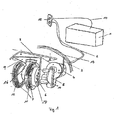
- a furniture roll in particular the double roller 7 shown in Fig. 1 comprises two wheels 11 and 12 which sit on a common axis, between the wheels, a roller body 16 is provided, in which a steering axis 20th (Fig. 3), which rotatably, in particular by 360 ° rotatably seated in a mounting plate 8, which is to be fastened to the base of the piece of furniture, for which the double roller 7 is provided.
- the wheel 12 is a freewheeling wheel and the wheel 11 is the driven wheel.
- a mounting bracket 9 is preferably made of metal with a leg on the reel body so fitted that the mounting bracket 9 together with the Reel body 16 and thus the double roller 7 rotates.
- the other angled part of the mounting bracket 9 extends laterally from the driven wheel 11 and carries a kit of a motor 4, in particular an electric 12 or 24 volt motor and a mounted gear fifth
- a sprocket adapter 6 which is fixedly connected to the driven wheel 11.
- the output shaft of the transmission 5 engages positively with an attached tooth edge.
- the transmission 5 is fastened by fastening screws 10 on the mounting bracket 9.
- the sprocket adapter 6 is attached via fastening screws 24 on the wheel 11.
- the electric motor 4 is electrically supplied via a sliding contact 3 and a contact ring 13, which is integrated in the mounting base of the piece of furniture or in the mounting plate 8.
- the power supply 14 consists of a battery 1, which is connected via a push-button 15 and a power cable 2 to the contact ring 13.
- the battery 1 is rechargeable.
- the key switch 15 serves to switch between the forward and the reverse drive of the drive device.
- a second electric motor is provided on the free-running wheel, the counter-rotating direction of the driven wheel 11, the double roller 7 turns and steers.
- the steering can be done via a remote control, which consists of a radio transmitter and a corresponding receiver on the drive device, via the received signal of the second motor is driven.
- the mounting bracket 9 mounting holes 17 through which the fastening screws 10 lead, with which the gear 5 is fixed to the mounting bracket 9.
- a Achsbohrung 18 through which the output shaft of the transmission is guided, which engages positively by means of the attached gear in the sprocket adapter 6.
- a snap closure 19 is provided for mounting on the roller body 16, with which the mounting bracket 9 is placed on the roller body 16.
- the steering axis 20 of the double roller 7 is guided in the interior of the roller body 16 via a sliding bearing 21.
- the snap closure 19 engages in the manner shown in Fig. 3 in the roller body 16 a.
- the steering axle 20 is mounted at its end via a ball bearing in the roller body 16.
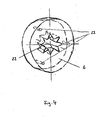
- Fig. 4 shows the sprocket adapter 6 in detail ..
- the sprocket adapter 6 consists of a plastic disc with mounting holes 23 for the mounting screws 24 and an inner sprocket 22, which is in the form of a sprocket cutout and preferably receives the gear fixed to the output shaft of the gear 5 positively.
- an inner sprocket 22 which is in the form of a sprocket cutout and preferably receives the gear fixed to the output shaft of the gear 5 positively.
- other forms of coupling between the output shaft of the transmission 5 and the adapter 6 are also conceivable.
- the drive device described above is particularly suitable as a wheel drive for a furniture roll with a maximum height of 105 mm and high load, as for example in mobile prints, Kitchenettes, demonstration desks, life support equipment, analyzers, hospital beds or similar mobile facilities are used in laboratories, hospitals, nursing homes or the like.
Landscapes
- Engineering & Computer Science (AREA)
- Mechanical Engineering (AREA)
- Gear Transmission (AREA)
- Power-Operated Mechanisms For Wings (AREA)
- Vending Machines For Individual Products (AREA)
- Gears, Cams (AREA)
- Invalid Beds And Related Equipment (AREA)
Abstract
Description
- Die Erfindung betrifft eine Antriebsvorrichtung für eine Lenkrolle eines Möbelstücks oder Gerätes, insbesondere eines Schwerlastmöbelstücks oder -gerätes, das z.B. in einem Laboratorium oder im Krankenhaus zum Einsatz kommt.
- Möbelstücke und Geräte mit großer Belastung, wie beispielsweise Labormöbelstücke, Lebenserhaltungsgeräte in Krankenhäusern oder Krankenbetten werden unter Verwendung von Lenkrollen, insbesondere Doppellenkrollen mobil gestaltet, die vorzugsweise um 360° drehend ausgebildet sind und deren Lenkung manuell erfolgt.
- Eine Doppellenkrolle besteht im Wesentlichen aus zwei Rädern, die auf einer gemeinsamen Achse angeordnet sind, wobei zwischen den beiden Rädern ein Rollenkörper vorgesehen ist, in dem eine Lenkachse angeordnet ist, die fest mit einer Montageplatte verbunden ist, die am Unterbau des Möbelstückes befestigt wird.
- Die der Erfindung zugrunde liegende Aufgabe besteht darin, eine Antriebsvorrichtung für eine derartige Lenkrolle eines Möbelstücks oder Gerätes zu schaffen, mit der die Lenkrolle bei Schwerbelastung angetrieben werden kann.
- Diese Aufgabe wird gemäß der Erfindung durch die Ausbildung gelöst, die im Anspruch 1 angegeben ist.
- Besonders bevorzugte Weiterbildungen und Ausgestaltungen der erfindungsgemäßen Vorrichtung sind Gegenstand der Ansprüche 2 bis 5.
- Im Folgenden wird anhand der zugehörigen Zeichnungen ein besonderes bevorzugtes Ausführungsbeispiel der erfindungsgemäßen Vorrichtung näher beschrieben. Es zeigen
- Fig. 1 in einer schematischen perspektivischen Ansicht das Ausführungsbeispiel der erfindungsgemäßen Antriebsvorrichtung,
- Fig. 2 in einer perspektivischen Ansicht den bei dem Ausführungsbeispiel von Fig. 1 dargestellten Montagewinkel im Einzelnen,
- Fig. 3 eine Schnittansicht durch die Lenkachse einer Doppellenkrolle bei dem in Fig. 1 dargestellten Ausführungsbeispiel und
- Fig. 4 eine perspektivische Ansicht des bei dem in Fig. 1 dargestellten Ausführungsbeispiels vorgesehen Zahnkranzadapters.
- Wie es in Fig. 1 dargestellt ist, umfasst eine Möbelrolle, insbesondere die in Fig. 1 dargestellte Doppellenkrolle 7 zwei Räder 11 und 12, die auf einer gemeinsamen Achse sitzen, wobei zwischen den Rädern ein Rollenkörper 16 vorgesehen ist, in dem eine Lenkachse 20 (Fig. 3) verläuft, die drehend, insbesondere um 360° drehend in einer Montageplatte 8 sitzt, die am Unterbau des Möbelstückes zu befestigen ist, für die die Doppellenkrolle 7 vorgesehen ist.
- Bei dem in Fig. 1 dargestellten Ausführungsbeispiel ist das Rad 12 ein freilaufendes Rad und ist das Rad 11 das angetriebene Rad. Zu diesem Zweck ist ein Montagewinkel 9 vorzugsweise aus Metall mit einem Schenkel auf den Rollenkörper so gepasst, dass der Montagewinkel 9 zusammen mit dem Rollenkörper 16 und damit der Doppellenkrolle 7 dreht. Das andere abgewinkelte Teil des Montagewinkels 9 verläuft seitlich vom angetriebenen Rad 11 und trägt einen Bausatz aus einem Motor 4, insbesondere einem elektrischen 12 oder 24 Volt-Motor und einem angebauten Getriebe 5.
- Zwischen dem abgewinkelten Teil des Montagewinkels 9, an dem der Motorgetriebebausatz angeordnet ist, und dem angetriebenen Rad 11 befindet sich ein Adapter, bei dem dargestellten Ausführungsbeispiel ein Zahnkranzadapter 6, der fest mit dem angetriebenen Rad 11 verbunden ist. In den Innenzahnkranz 22 (Fig. 4) des Zahnkranzadapters 6 greift die Ausgangswelle des Getriebes 5 mit einem angesetzten Zahnrand formschlüssig ein.
- Das Getriebe 5 ist über Befestigungsschrauben 10 am Montagewinkel 9 befestigt. Der Zahnkranzadapter 6 ist über Befestigungsschrauben 24 am Rad 11 befestigt.
- Der Elektromotor 4 wird über einen Schleifkontakt 3 und einen Kontaktring 13 elektrisch versorgt, der im Montageboden des Möbelstücks oder in der Montageplatte 8 integriert ist. Die Stromversorgung 14 besteht aus einer Batterie 1, die über einen Tastschalter 15 und ein Versorgungskabel 2 mit dem Kontaktring 13 verbunden ist. Die Batterie 1 ist wieder aufladbar.
- Der Tastschalter 15 dient dazu, zwischen der Vorwärts- und dem Rückwärtsantrieb der Antriebsvorrichtung umzuschalten.
- Im Falle einer motorischen Lenkung der Doppellenkrolle ist am freilaufenden Rad 12 ein zweiter Elektromotor vorgesehen, der durch gegenläufige Drehrichtung zum angetriebenen Rad 11 die Doppellenkrolle 7 dreht und damit lenkt. Die Lenkung kann über eine Fernbedienung erfolgen, die aus einem Funksender und einem dementsprechenden Empfänger an der Antriebsvorrichtung besteht, über dessen Empfangssignal der zweite Motor angesteuert wird.
- Wie es im Einzelnen in Fig. 2 dargestellt ist, weist der Montagewinkel 9 Befestigungsbohrungen 17 auf, durch die die Befestigungsschrauben 10 führen, mit denen das Getriebe 5 am Montagewinkel 9 befestigt ist. In demselben Schenkel des Montagewinkels 9 befindet sich weiterhin eine Achsbohrung 18, durch die die Ausgangswelle des Getriebes geführt ist, die mittels des aufgesetzten Zahnrads in den Zahnkranzadapter 6 formschlüssig eingreift.
- An dem anderen Schenkel des Montagewinkels 9 ist zur Montage am Rollenkörper 16 ein Schnappverschluss 19 vorgesehen, mit dem der Montagewinkel 9 auf den Rollenkörper 16 aufgesetzt ist.
- Wie es in Fig. 3 dargestellt ist, ist die Lenkachse 20 der Doppellenkrolle 7 im Inneren des Rollenkörpers 16 über ein Gleitlager 21 geführt. Der Schnappverschluss 19 greift in der in Fig. 3 darstellten Weise in den Rollenkörper 16 ein. Die Lenkachse 20 ist an ihrem Ende über ein Kugellager im Rollenkörper 16 gelagert.
- Fig. 4 zeigt den Zahnkranzadapter 6 im Einzelnen..
- Der Zahnkranzadapter 6 besteht aus einer Kunststoffscheibe mit Befestigungsbohrungen 23 für die Befestigungsschrauben 24 und einem inneren Zahnkranz 22, der in Form eines Zahnkranzausschnittes ausgebildet ist und das auf der Ausgangswelle des Getriebes 5 befestigte Zahnrad vorzugsweise formschlüssig aufnimmt. Es sind allerdings auch andere Formen der Kupplung zwischen der Ausgangswelle des Getriebes 5 und dem Adapter 6 denkbar.
- Die oben beschriebene Antriebsvorrichtung eignet sich insbesondere als Radantrieb für eine Möbelrolle mit maximaler Bauhöhe von 105 mm und hoher Belastung, wie es beispielsweise bei mobilen Abzügen, Küchenzeilen, Demonstrationstischen, Lebenserhaltungsgeräten, Analysegeräten, Krankenbetten oder ähnlichen mobilen Einrichtungen der Fall ist, die in Laboren, Krankenhäusern, Pflegeheimen oder dgl. zum Einsatz kommen.
Claims (5)
- Antriebsvorrichtung für eine Lenkrolle eines Möbelstücks oder Gerätes, insbesondere eines Schwerlastmöbelstücks oder -gerätes, dadurch gekennzeichnet, dass- an der Lenkrolle (7) ein sich drehendes Halteelement (9) vorgesehen ist, das einen Antriebsmotor (4) mit angebauten Getriebe (5) hält, und- an der Lenkrolle (7) ein Adapter (6) angebracht ist, in den die Ausgangwelle des Getriebes (5) formschlüssig eingreift.
- Antriebsvorrichtung nach Anspruch 1, dadurch gekennzeichnet, dass auf der Ausgangswelle des Getriebes (5) ein Zahnrad sitzt, mit dem die Ausgangswelle in den Adapter (6) eingreift.
- Antriebsvorrichtung nach Anspruch 1 oder 2, dadurch gekennzeichnet, dass der Adapter (6) aus einer Scheibe mit einem Zahnkranzausschnitt zur Aufnahme der Ausgangswelle des Getriebes (5) besteht.
- Antriebsvorrichtung nach Anspruch 1, 2 oder 3, dadurch gekennzeichnet, dass das Halteelement (9) ein Winkel, insbesondere Metallwinkel ist, der an einem Rollenkörper der Lenkrolle so angebracht ist, dass er sich mit dieser dreht.
- Antriebsvorrichtung nach einem der vorhergehenden Ansprüche, dadurch gekennzeichnet, dass die Lenkrolle eine Doppellenkrolle (7) ist, auf deren Rollenkörper (16) das Halteelement (9) über einen Schnappverschluss (19) aufgesetzt ist.
Applications Claiming Priority (1)
| Application Number | Priority Date | Filing Date | Title |
|---|---|---|---|
| DE102005007898A DE102005007898A1 (de) | 2005-02-21 | 2005-02-21 | Antriebsvorrichtung für eine Lenkrolle eines Möbelstücks |
Publications (2)
| Publication Number | Publication Date |
|---|---|
| EP1693228A1 true EP1693228A1 (de) | 2006-08-23 |
| EP1693228B1 EP1693228B1 (de) | 2010-04-07 |
Family
ID=36424649
Family Applications (1)
| Application Number | Title | Priority Date | Filing Date |
|---|---|---|---|
| EP06000141A Expired - Lifetime EP1693228B1 (de) | 2005-02-21 | 2006-01-04 | Antriebsvorrichtung für eine Lenkrolle eines Möbelstücks |
Country Status (3)
| Country | Link |
|---|---|
| EP (1) | EP1693228B1 (de) |
| AT (1) | ATE463355T1 (de) |
| DE (2) | DE102005007898A1 (de) |
Cited By (1)
| Publication number | Priority date | Publication date | Assignee | Title |
|---|---|---|---|---|
| NO20190806A1 (en) * | 2019-06-27 | 2020-12-28 | Wheel Me As | Wormscrew for displacement of wheel |
Families Citing this family (2)
| Publication number | Priority date | Publication date | Assignee | Title |
|---|---|---|---|---|
| CN103317965A (zh) * | 2013-06-04 | 2013-09-25 | 叶林森 | 电动脚轮 |
| DE202018106716U1 (de) | 2018-11-26 | 2018-12-06 | Franz Laudenbach | Laufrolle für einen Transportwagen und Transportwagen mit einer solchen Laufrolle |
Citations (4)
| Publication number | Priority date | Publication date | Assignee | Title |
|---|---|---|---|---|
| GB2183566A (en) * | 1985-11-18 | 1987-06-10 | Yoshida Kogyo Kk | Wagon with caster wheels |
| DE3943260A1 (de) * | 1989-12-29 | 1991-07-04 | Kurt Lennartz | Vorrichtung an fahrzeugen zur ueberwindung von fahrhindernissen |
| US5950749A (en) | 1997-01-23 | 1999-09-14 | Exedy Corporation | Automotive vehicle running on brakeable ball-bearing casters |
| DE19949351A1 (de) * | 1999-10-13 | 2001-07-12 | Hanebeck Uwe D | Aufbau von Radmodulen zur kombinierten Lenkung und Antrieb eines Fahrzeugs und ein Verfahren zu dessen elektronischer Kopplung |
-
2005
- 2005-02-21 DE DE102005007898A patent/DE102005007898A1/de not_active Withdrawn
-
2006
- 2006-01-04 AT AT06000141T patent/ATE463355T1/de not_active IP Right Cessation
- 2006-01-04 EP EP06000141A patent/EP1693228B1/de not_active Expired - Lifetime
- 2006-01-04 DE DE502006006617T patent/DE502006006617D1/de not_active Expired - Lifetime
Patent Citations (4)
| Publication number | Priority date | Publication date | Assignee | Title |
|---|---|---|---|---|
| GB2183566A (en) * | 1985-11-18 | 1987-06-10 | Yoshida Kogyo Kk | Wagon with caster wheels |
| DE3943260A1 (de) * | 1989-12-29 | 1991-07-04 | Kurt Lennartz | Vorrichtung an fahrzeugen zur ueberwindung von fahrhindernissen |
| US5950749A (en) | 1997-01-23 | 1999-09-14 | Exedy Corporation | Automotive vehicle running on brakeable ball-bearing casters |
| DE19949351A1 (de) * | 1999-10-13 | 2001-07-12 | Hanebeck Uwe D | Aufbau von Radmodulen zur kombinierten Lenkung und Antrieb eines Fahrzeugs und ein Verfahren zu dessen elektronischer Kopplung |
Cited By (2)
| Publication number | Priority date | Publication date | Assignee | Title |
|---|---|---|---|---|
| NO20190806A1 (en) * | 2019-06-27 | 2020-12-28 | Wheel Me As | Wormscrew for displacement of wheel |
| NO345547B1 (en) * | 2019-06-27 | 2021-04-12 | Wheel Me As | Wormscrew for displacement of wheel |
Also Published As
| Publication number | Publication date |
|---|---|
| EP1693228B1 (de) | 2010-04-07 |
| DE502006006617D1 (de) | 2010-05-20 |
| DE102005007898A1 (de) | 2006-08-24 |
| ATE463355T1 (de) | 2010-04-15 |
Similar Documents
| Publication | Publication Date | Title |
|---|---|---|
| DE102016108663B4 (de) | Elektrischer Ratschenschlüssel | |
| DE60106085T2 (de) | Tragbare schere mit motorantrieb | |
| EP3700799B1 (de) | Lenksäule für ein kraftfahrzeug | |
| DE102015118300B4 (de) | Elektrischer Ratschenschlüssel | |
| EP2086372A1 (de) | Antriebsvorrichtung für bewegliche möbelteile | |
| EP0674122B1 (de) | Getriebemotor | |
| EP3622930A2 (de) | Hilfsantriebsvorrichtung für einen rollstuhl | |
| WO2004071244A3 (de) | Elektromotorischer linearantrieb | |
| WO2014009270A1 (de) | Verstellantrieb | |
| DE4333375B4 (de) | Antriebsvorrichtung für einen Roboter | |
| EP0911471A2 (de) | Feststeller für schwenkbar angelenkte Bauteile | |
| DE102011016456B4 (de) | Positioniervorrichtung | |
| EP1693228B1 (de) | Antriebsvorrichtung für eine Lenkrolle eines Möbelstücks | |
| DE102021119533A1 (de) | Chirurgisches Instrument und Lenkgetriebe dafür | |
| DE102007001469B4 (de) | Vorsatzgerät für einen Drehmomentschlüssel | |
| EP1084603B1 (de) | Sämaschine mit einstellbarer Särate | |
| DE202019102684U1 (de) | Verstellwerkzeug für Verstellteile von insbesondere Sockelfüßen für Möbel | |
| EP2188151B1 (de) | Antriebseinrichtung | |
| DE2616100C3 (de) | Schraubenschlüssel mit Handantrieb eines Einfachst-Planetengetriebes | |
| DE20214426U1 (de) | Elektromotorischer Möbelantrieb zum Verstellen von Teilen eines Möbels relativ zueinander | |
| EP1201370B1 (de) | Elektrisch betätigbare Werkstück-Spannvorrichtung | |
| DE10254129B4 (de) | Elektromotorischer Möbelantrieb zum Verstellen von Teilen eines Möbels relativ zueinander | |
| DE202022101282U1 (de) | Betätigungsvorrichtung für ein Türschloss | |
| DE102006014540A1 (de) | Einstellvorrichtung für Zahnstangen | |
| DE102010035555A1 (de) | Elektromotorischer Schwenkantrieb, insbesondere für Klappen, beispielsweise an Möbeln |
Legal Events
| Date | Code | Title | Description |
|---|---|---|---|
| PUAI | Public reference made under article 153(3) epc to a published international application that has entered the european phase |
Free format text: ORIGINAL CODE: 0009012 |
|
| AK | Designated contracting states |
Kind code of ref document: A1 Designated state(s): AT BE BG CH CY CZ DE DK EE ES FI FR GB GR HU IE IS IT LI LT LU LV MC NL PL PT RO SE SI SK TR |
|
| AX | Request for extension of the european patent |
Extension state: AL BA HR MK YU |
|
| 17P | Request for examination filed |
Effective date: 20070130 |
|
| AKX | Designation fees paid |
Designated state(s): AT BE BG CH CY CZ DE DK EE ES FI FR GB GR HU IE IS IT LI LT LU LV MC NL PL PT RO SE SI SK TR |
|
| 17Q | First examination report despatched |
Effective date: 20080305 |
|
| GRAP | Despatch of communication of intention to grant a patent |
Free format text: ORIGINAL CODE: EPIDOSNIGR1 |
|
| GRAS | Grant fee paid |
Free format text: ORIGINAL CODE: EPIDOSNIGR3 |
|
| GRAA | (expected) grant |
Free format text: ORIGINAL CODE: 0009210 |
|
| AK | Designated contracting states |
Kind code of ref document: B1 Designated state(s): AT BE BG CH CY CZ DE DK EE ES FI FR GB GR HU IE IS IT LI LT LU LV MC NL PL PT RO SE SI SK TR |
|
| REG | Reference to a national code |
Ref country code: GB Ref legal event code: FG4D Free format text: NOT ENGLISH |
|
| REG | Reference to a national code |
Ref country code: CH Ref legal event code: EP |
|
| REG | Reference to a national code |
Ref country code: IE Ref legal event code: FG4D Free format text: LANGUAGE OF EP DOCUMENT: GERMAN |
|
| REF | Corresponds to: |
Ref document number: 502006006617 Country of ref document: DE Date of ref document: 20100520 Kind code of ref document: P |
|
| REG | Reference to a national code |
Ref country code: DE Ref legal event code: R096 Ref document number: 502006006617 Country of ref document: DE Effective date: 20100520 |
|
| REG | Reference to a national code |
Ref country code: NL Ref legal event code: VDEP Effective date: 20100407 |
|
| PG25 | Lapsed in a contracting state [announced via postgrant information from national office to epo] |
Ref country code: SI Free format text: LAPSE BECAUSE OF FAILURE TO SUBMIT A TRANSLATION OF THE DESCRIPTION OR TO PAY THE FEE WITHIN THE PRESCRIBED TIME-LIMIT Effective date: 20100407 |
|
| LTIE | Lt: invalidation of european patent or patent extension |
Effective date: 20100407 |
|
| REG | Reference to a national code |
Ref country code: IE Ref legal event code: FD4D |
|
| PG25 | Lapsed in a contracting state [announced via postgrant information from national office to epo] |
Ref country code: LT Free format text: LAPSE BECAUSE OF FAILURE TO SUBMIT A TRANSLATION OF THE DESCRIPTION OR TO PAY THE FEE WITHIN THE PRESCRIBED TIME-LIMIT Effective date: 20100407 Ref country code: NL Free format text: LAPSE BECAUSE OF FAILURE TO SUBMIT A TRANSLATION OF THE DESCRIPTION OR TO PAY THE FEE WITHIN THE PRESCRIBED TIME-LIMIT Effective date: 20100407 Ref country code: SE Free format text: LAPSE BECAUSE OF FAILURE TO SUBMIT A TRANSLATION OF THE DESCRIPTION OR TO PAY THE FEE WITHIN THE PRESCRIBED TIME-LIMIT Effective date: 20100407 Ref country code: ES Free format text: LAPSE BECAUSE OF FAILURE TO SUBMIT A TRANSLATION OF THE DESCRIPTION OR TO PAY THE FEE WITHIN THE PRESCRIBED TIME-LIMIT Effective date: 20100718 |
|
| PG25 | Lapsed in a contracting state [announced via postgrant information from national office to epo] |
Ref country code: IS Free format text: LAPSE BECAUSE OF FAILURE TO SUBMIT A TRANSLATION OF THE DESCRIPTION OR TO PAY THE FEE WITHIN THE PRESCRIBED TIME-LIMIT Effective date: 20100807 Ref country code: FI Free format text: LAPSE BECAUSE OF FAILURE TO SUBMIT A TRANSLATION OF THE DESCRIPTION OR TO PAY THE FEE WITHIN THE PRESCRIBED TIME-LIMIT Effective date: 20100407 Ref country code: LV Free format text: LAPSE BECAUSE OF FAILURE TO SUBMIT A TRANSLATION OF THE DESCRIPTION OR TO PAY THE FEE WITHIN THE PRESCRIBED TIME-LIMIT Effective date: 20100407 |
|
| PG25 | Lapsed in a contracting state [announced via postgrant information from national office to epo] |
Ref country code: GR Free format text: LAPSE BECAUSE OF FAILURE TO SUBMIT A TRANSLATION OF THE DESCRIPTION OR TO PAY THE FEE WITHIN THE PRESCRIBED TIME-LIMIT Effective date: 20100708 Ref country code: CY Free format text: LAPSE BECAUSE OF FAILURE TO SUBMIT A TRANSLATION OF THE DESCRIPTION OR TO PAY THE FEE WITHIN THE PRESCRIBED TIME-LIMIT Effective date: 20100428 Ref country code: PL Free format text: LAPSE BECAUSE OF FAILURE TO SUBMIT A TRANSLATION OF THE DESCRIPTION OR TO PAY THE FEE WITHIN THE PRESCRIBED TIME-LIMIT Effective date: 20100407 |
|
| PG25 | Lapsed in a contracting state [announced via postgrant information from national office to epo] |
Ref country code: DK Free format text: LAPSE BECAUSE OF FAILURE TO SUBMIT A TRANSLATION OF THE DESCRIPTION OR TO PAY THE FEE WITHIN THE PRESCRIBED TIME-LIMIT Effective date: 20100407 Ref country code: IE Free format text: LAPSE BECAUSE OF FAILURE TO SUBMIT A TRANSLATION OF THE DESCRIPTION OR TO PAY THE FEE WITHIN THE PRESCRIBED TIME-LIMIT Effective date: 20100407 Ref country code: PT Free format text: LAPSE BECAUSE OF FAILURE TO SUBMIT A TRANSLATION OF THE DESCRIPTION OR TO PAY THE FEE WITHIN THE PRESCRIBED TIME-LIMIT Effective date: 20100809 Ref country code: EE Free format text: LAPSE BECAUSE OF FAILURE TO SUBMIT A TRANSLATION OF THE DESCRIPTION OR TO PAY THE FEE WITHIN THE PRESCRIBED TIME-LIMIT Effective date: 20100407 |
|
| PLBE | No opposition filed within time limit |
Free format text: ORIGINAL CODE: 0009261 |
|
| STAA | Information on the status of an ep patent application or granted ep patent |
Free format text: STATUS: NO OPPOSITION FILED WITHIN TIME LIMIT |
|
| PG25 | Lapsed in a contracting state [announced via postgrant information from national office to epo] |
Ref country code: SK Free format text: LAPSE BECAUSE OF FAILURE TO SUBMIT A TRANSLATION OF THE DESCRIPTION OR TO PAY THE FEE WITHIN THE PRESCRIBED TIME-LIMIT Effective date: 20100407 Ref country code: RO Free format text: LAPSE BECAUSE OF FAILURE TO SUBMIT A TRANSLATION OF THE DESCRIPTION OR TO PAY THE FEE WITHIN THE PRESCRIBED TIME-LIMIT Effective date: 20100407 Ref country code: CZ Free format text: LAPSE BECAUSE OF FAILURE TO SUBMIT A TRANSLATION OF THE DESCRIPTION OR TO PAY THE FEE WITHIN THE PRESCRIBED TIME-LIMIT Effective date: 20100407 |
|
| 26N | No opposition filed |
Effective date: 20110110 |
|
| PG25 | Lapsed in a contracting state [announced via postgrant information from national office to epo] |
Ref country code: IT Free format text: LAPSE BECAUSE OF FAILURE TO SUBMIT A TRANSLATION OF THE DESCRIPTION OR TO PAY THE FEE WITHIN THE PRESCRIBED TIME-LIMIT Effective date: 20100407 |
|
| REG | Reference to a national code |
Ref country code: DE Ref legal event code: R097 Ref document number: 502006006617 Country of ref document: DE Effective date: 20110110 |
|
| BERE | Be: lapsed |
Owner name: WALDNER LABOR- UND SCHULEINRICHTUNGEN G.M.B.H. Effective date: 20110131 |
|
| PG25 | Lapsed in a contracting state [announced via postgrant information from national office to epo] |
Ref country code: MC Free format text: LAPSE BECAUSE OF NON-PAYMENT OF DUE FEES Effective date: 20110131 |
|
| REG | Reference to a national code |
Ref country code: CH Ref legal event code: PL |
|
| GBPC | Gb: european patent ceased through non-payment of renewal fee |
Effective date: 20110104 |
|
| REG | Reference to a national code |
Ref country code: FR Ref legal event code: ST Effective date: 20110930 |
|
| PG25 | Lapsed in a contracting state [announced via postgrant information from national office to epo] |
Ref country code: LI Free format text: LAPSE BECAUSE OF NON-PAYMENT OF DUE FEES Effective date: 20110131 Ref country code: FR Free format text: LAPSE BECAUSE OF NON-PAYMENT OF DUE FEES Effective date: 20110131 Ref country code: CH Free format text: LAPSE BECAUSE OF NON-PAYMENT OF DUE FEES Effective date: 20110131 |
|
| PG25 | Lapsed in a contracting state [announced via postgrant information from national office to epo] |
Ref country code: BE Free format text: LAPSE BECAUSE OF NON-PAYMENT OF DUE FEES Effective date: 20110131 Ref country code: GB Free format text: LAPSE BECAUSE OF NON-PAYMENT OF DUE FEES Effective date: 20110104 |
|
| REG | Reference to a national code |
Ref country code: AT Ref legal event code: MM01 Ref document number: 463355 Country of ref document: AT Kind code of ref document: T Effective date: 20110104 |
|
| PG25 | Lapsed in a contracting state [announced via postgrant information from national office to epo] |
Ref country code: AT Free format text: LAPSE BECAUSE OF NON-PAYMENT OF DUE FEES Effective date: 20110104 |
|
| PG25 | Lapsed in a contracting state [announced via postgrant information from national office to epo] |
Ref country code: LU Free format text: LAPSE BECAUSE OF NON-PAYMENT OF DUE FEES Effective date: 20110104 |
|
| PG25 | Lapsed in a contracting state [announced via postgrant information from national office to epo] |
Ref country code: TR Free format text: LAPSE BECAUSE OF FAILURE TO SUBMIT A TRANSLATION OF THE DESCRIPTION OR TO PAY THE FEE WITHIN THE PRESCRIBED TIME-LIMIT Effective date: 20100407 Ref country code: BG Free format text: LAPSE BECAUSE OF FAILURE TO SUBMIT A TRANSLATION OF THE DESCRIPTION OR TO PAY THE FEE WITHIN THE PRESCRIBED TIME-LIMIT Effective date: 20100707 |
|
| PG25 | Lapsed in a contracting state [announced via postgrant information from national office to epo] |
Ref country code: HU Free format text: LAPSE BECAUSE OF FAILURE TO SUBMIT A TRANSLATION OF THE DESCRIPTION OR TO PAY THE FEE WITHIN THE PRESCRIBED TIME-LIMIT Effective date: 20100407 |
|
| REG | Reference to a national code |
Ref country code: DE Ref legal event code: R082 Ref document number: 502006006617 Country of ref document: DE Representative=s name: KOTITSCHKE & HEURUNG PARTNERSCHAFT MBB PATENT-, DE Ref country code: DE Ref legal event code: R082 Ref document number: 502006006617 Country of ref document: DE Representative=s name: KOTITSCHKE & HEURUNG PARTNERSCHAFT, DE Ref country code: DE Ref legal event code: R082 Ref document number: 502006006617 Country of ref document: DE Representative=s name: KOTITSCHKE & HEURUNG PARTNERSCHAFT MBB, DE Ref country code: DE Ref legal event code: R082 Ref document number: 502006006617 Country of ref document: DE Representative=s name: DR. RALF KOTITSCHKE, DE |
|
| PGFP | Annual fee paid to national office [announced via postgrant information from national office to epo] |
Ref country code: DE Payment date: 20170125 Year of fee payment: 12 |
|
| REG | Reference to a national code |
Ref country code: DE Ref legal event code: R119 Ref document number: 502006006617 Country of ref document: DE |
|
| PG25 | Lapsed in a contracting state [announced via postgrant information from national office to epo] |
Ref country code: DE Free format text: LAPSE BECAUSE OF NON-PAYMENT OF DUE FEES Effective date: 20180801 |
|
| P01 | Opt-out of the competence of the unified patent court (upc) registered |
Effective date: 20230515 |