EP1693139B1 - Welding-wire packing container with internal winding retention system. - Google Patents
Welding-wire packing container with internal winding retention system. Download PDFInfo
- Publication number
- EP1693139B1 EP1693139B1 EP06300066A EP06300066A EP1693139B1 EP 1693139 B1 EP1693139 B1 EP 1693139B1 EP 06300066 A EP06300066 A EP 06300066A EP 06300066 A EP06300066 A EP 06300066A EP 1693139 B1 EP1693139 B1 EP 1693139B1
- Authority
- EP
- European Patent Office
- Prior art keywords
- wire
- drum
- central
- welding
- container according
- Prior art date
- Legal status (The legal status is an assumption and is not a legal conclusion. Google has not performed a legal analysis and makes no representation as to the accuracy of the status listed.)
- Active
Links
- 230000014759 maintenance of location Effects 0.000 title 1
- 238000012856 packing Methods 0.000 title 1
- 238000004804 winding Methods 0.000 title 1
- 238000003466 welding Methods 0.000 claims abstract description 29
- 238000004806 packaging method and process Methods 0.000 claims abstract description 9
- 238000009434 installation Methods 0.000 claims abstract description 4
- 230000002093 peripheral effect Effects 0.000 claims description 26
- 229920000642 polymer Polymers 0.000 claims description 6
- 241000219504 Caryophyllales Species 0.000 description 4
- 239000004033 plastic Substances 0.000 description 4
- 229910000831 Steel Inorganic materials 0.000 description 3
- 230000003750 conditioning effect Effects 0.000 description 3
- 239000000463 material Substances 0.000 description 3
- 239000010959 steel Substances 0.000 description 3
- 238000004026 adhesive bonding Methods 0.000 description 2
- 230000015572 biosynthetic process Effects 0.000 description 2
- 238000005755 formation reaction Methods 0.000 description 2
- 230000005484 gravity Effects 0.000 description 2
- 238000004519 manufacturing process Methods 0.000 description 2
- 239000002184 metal Substances 0.000 description 2
- 238000005219 brazing Methods 0.000 description 1
- 238000010276 construction Methods 0.000 description 1
- 238000010891 electric arc Methods 0.000 description 1
- 229920005570 flexible polymer Polymers 0.000 description 1
- 238000003698 laser cutting Methods 0.000 description 1
- 238000012423 maintenance Methods 0.000 description 1
- 229910001092 metal group alloy Inorganic materials 0.000 description 1
- 239000002985 plastic film Substances 0.000 description 1
- 230000000750 progressive effect Effects 0.000 description 1
Images
Classifications
-
- B—PERFORMING OPERATIONS; TRANSPORTING
- B23—MACHINE TOOLS; METAL-WORKING NOT OTHERWISE PROVIDED FOR
- B23K—SOLDERING OR UNSOLDERING; WELDING; CLADDING OR PLATING BY SOLDERING OR WELDING; CUTTING BY APPLYING HEAT LOCALLY, e.g. FLAME CUTTING; WORKING BY LASER BEAM
- B23K9/00—Arc welding or cutting
- B23K9/12—Automatic feeding or moving of electrodes or work for spot or seam welding or cutting
- B23K9/133—Means for feeding electrodes, e.g. drums, rolls, motors
- B23K9/1333—Dereeling means
-
- B—PERFORMING OPERATIONS; TRANSPORTING
- B65—CONVEYING; PACKING; STORING; HANDLING THIN OR FILAMENTARY MATERIAL
- B65D—CONTAINERS FOR STORAGE OR TRANSPORT OF ARTICLES OR MATERIALS, e.g. BAGS, BARRELS, BOTTLES, BOXES, CANS, CARTONS, CRATES, DRUMS, JARS, TANKS, HOPPERS, FORWARDING CONTAINERS; ACCESSORIES, CLOSURES, OR FITTINGS THEREFOR; PACKAGING ELEMENTS; PACKAGES
- B65D85/00—Containers, packaging elements or packages, specially adapted for particular articles or materials
- B65D85/02—Containers, packaging elements or packages, specially adapted for particular articles or materials for annular articles
- B65D85/04—Containers, packaging elements or packages, specially adapted for particular articles or materials for annular articles for coils of wire, rope or hose
-
- B—PERFORMING OPERATIONS; TRANSPORTING
- B65—CONVEYING; PACKING; STORING; HANDLING THIN OR FILAMENTARY MATERIAL
- B65H—HANDLING THIN OR FILAMENTARY MATERIAL, e.g. SHEETS, WEBS, CABLES
- B65H49/00—Unwinding or paying-out filamentary material; Supporting, storing or transporting packages from which filamentary material is to be withdrawn or paid-out
- B65H49/02—Methods or apparatus in which packages do not rotate
-
- B—PERFORMING OPERATIONS; TRANSPORTING
- B65—CONVEYING; PACKING; STORING; HANDLING THIN OR FILAMENTARY MATERIAL
- B65H—HANDLING THIN OR FILAMENTARY MATERIAL, e.g. SHEETS, WEBS, CABLES
- B65H57/00—Guides for filamentary materials; Supports therefor
- B65H57/18—Guides for filamentary materials; Supports therefor mounted to facilitate unwinding of material from packages
Definitions
- the present invention relates to a welding wire packaging container, wherein the wire spool is held by a movable internal retaining device within the barrel to effectively maintain the wire turns in position.
- the fusible son or electrode-electrodes used in welding are conventionally packaged in coils and placed in containers or packaging drums, in particular for conveying them to their place of use.
- the wire is progressively driven, by means of a wire feeding device, and conveyed to a welding torch where the free end of the wire is gradually melted in an electric arc established between the wire and the part to be welded, a laser beam or the like, and the metal of the wire thus melted is deposited on the part or parts to be welded so as to form a welding, brazing joint or similar.
- the wire spool gradually unwinds as the wire is used.
- the wire being packaged in a coil tends to unwittingly form loops and nodes, during its unwinding, which pose problems, such as tangles, unwinding irregularities or the like.
- EP-A-1053189 , EP-A-1357059 , EP-A-1057751 , EP-A-1295813 , EP-A-1275595 and EP-A-1352838 propose using such retainers to be placed on the spool of wire to prevent intermingling of the turns of wire when the wire is removed from the coil.
- These retainers may be associated with guiding devices, fixed or not to the closure lid of the drum, for guiding the wire towards the outside of the drum during its unwinding.
- the retainer is in contact, at least at some points, with the inner walls of the body.
- the contact can be made directly via the edges of the retaining device when the latter is a washer or a circular or polygonal disc shaped to fit the internal shapes of the barrel or indirectly via legs, fingers, expansions or the like carried by the retaining device and coming into contact with the inner wall of the drum or guided by guides carried by the barrel wall or arranged therein.
- the retaining device is formed of a washer or a perforated disc at its center to let the wire and dimensioned to come into contact with the inner wall of the drum in which the coil is disposed, it appeared in practice, coil turns tended, by virtue of their elasticity, to lift the disk and to pass between the inner wall of the drum and the rim of the disk, which causes entanglements and blockages of the wire preventing its good unwinding .
- the solution provided by the present invention is a welding wire conditioning container comprising a shank for receiving the welding wire, and a wire retaining device positioned in the shank so as to press against the turns of wire, comprising a rigid central portion pierced with a central orifice through which the wire passes, said central portion having a dimension smaller than the internal diameter of the barrel, characterized in that the wire retainer further comprises a flexible peripheral portion and deformable formed of one or more sheets and having a dimension greater than the internal diameter of the barrel.
- the invention also relates to a wire retainer as such for a welding wire packaging container.
- the invention also relates to an automated fused wire arc welding installation comprising an arc welding torch fed with a fuse wire, characterized in that the wire comes from a packaging container according to the invention. 'invention.
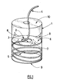
- a welding wire packaging container according to the invention is shown schematically in the accompanying Figures.
- the container is formed of a barrel 1 provided with a lower bottom 9 and is dimensioned to receive the pre-twisted welding wire 4 and being curled in the barrel 1 in a ring 5 of wire, commonly called coil.
- a wire retainer 2 is inserted into the barrel 1 and is positioned on the spool 5 so as to press, by gravity, on the thread turns 4 while keeping them in position during the unwinding of the thread 4, during its use in welding.
- the retaining device 2 is axially movable in the barrel 1 since it progressively descends as the wire 4 is extracted and thus the height of the coil 5 is reduced.
- the barrel 1 is, in addition, surmounted by an upper lid 10 which may or may not be separable from the barrel 1.
- the barrel 1 may be cylindrical or polygonal, but in general it is cylindrical with a vertical wall.
- the bottom 9 and the lid 10 may be formed in one piece with the barrel 1, for example within the same thick sheet of cardboard or the like, cut and shaped to the desired dimensions, or else several pieces or elements associated with each other to form the container, for example cardboard pieces or the like.
- the container of the invention can be arranged on a pallet and / or equipped with straps or the like to allow its lifting at its place of use.
- the barrel 1 can itself be inserted into an outer box, for example a box of polygonal shape, such as a square box (not shown).
- an outer box for example a box of polygonal shape, such as a square box (not shown).
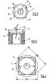
- the wire retainer 2 comprises a rigid central portion 6 pierced with a central orifice 3 through which the wire 4 passes and a flexible and deformable peripheral portion 7.
- the central portion 6 is in the form of a ring or disk pierced in the center of the orifice 3, while the peripheral portion 7 is formed of one or more sheets preferably of a plastic material (polymer) resistant to wear by friction of the wire 4 during its course.
- a plastic material polymer
- the central portion 6 has a dimension Dr, for example a diameter of the pierced disc, smaller than the internal diameter Df of the barrel 1, while the flexible and deformable peripheral portion 7 has at least one dimension Dp, for example a diagonal length Dp in the case of a square sheet, greater than the internal diameter Df of the barrel 1.
- the central portion 6 may be fixed to the peripheral portion 7 by any suitable fastening means, for example by gluing.
- central portion 6 can be simply secured to the peripheral portion 7 by means of a precise dimensioning of one with respect to the other, as explained below.
- the retaining device 2 In order to ensure effective support of the retaining device 2 on the turns, it is made of a heavy material, such as a metal or a metal alloy, for example steel or the like, or it is ballasted with a ballast having sufficient weight to achieve the desired maintenance of the turns of wire.
- a heavy material such as a metal or a metal alloy, for example steel or the like
- peripheral portion 7 is flexible and deformable and has at least one dimension Dp greater than the internal diameter Df of the barrel 1 allows this portion 7 to perfectly marry the contours of the inner wall of the barrel 1 since the corner portions 8 of this part 7 rise slightly along said inner wall of the barrel 1, as shown schematically on the figure 1 , thus preventing wire turns 4 from passing between the peripheral edge of the central disc 6 and the inner wall of the drum 1.
- the portions 8 protruding from the plastic sheet (s) 7, that is to say going beyond the peripheral rim of the disc 6, must imperatively be located above the disc 6, that is to say, lead from the upper side of the barrel through which the wire 4 is extracted.
- a guide cylinder 11 can be inserted in the center of the wire coil 4 and have an outside diameter smaller than the diameter of the orifice 3 so as to allow said guide cylinder 11 to pass through the orifice 3 as the wire is unwound.
- the retaining device 2 can be easily manufactured, for example from a perforated disk 6 made of steel, for example obtained by laser cutting of a steel sheet, which is positioned in a parallelepipedal cover made of material plastic forming the peripheral part 7.
- the wall of the cover constitutes the polymer sheets of the peripheral portion 7.
- cover designates any pocket, bag or the like of sufficient size to receive the disc 6.
- the opening of the cover is then folded and the cover closed by thermal welding, gluing, stapling or the like, which allows to secure the disc 6 and the walls of the plastic cover 7 without forcing them to stick with each other. 'other.
- the retaining device 2 is then ready to be put into operation in the barrel 1 as explained above, taking care to position the corner portions 8 of the flexible polymer cover 7 towards the upper part of the barrel 1.
- the container of the invention is easy to manufacture, low cost, easy to implement and has shown great efficiency in feasibility tests that have been performed.
- the wire conditioning container of the invention can be used to power an automated fused arc welding installation comprising an arc welding torch powered with one or more fusible wires, particularly for MIG welding. or MAG, or for laser-arc hybrid welding with fusible electrode, especially robotized.
Landscapes
- Engineering & Computer Science (AREA)
- Mechanical Engineering (AREA)
- Physics & Mathematics (AREA)
- Plasma & Fusion (AREA)
- Unwinding Of Filamentary Materials (AREA)
- Packaging Of Annular Or Rod-Shaped Articles, Wearing Apparel, Cassettes, Or The Like (AREA)
- Lining Or Joining Of Plastics Or The Like (AREA)
- Basic Packing Technique (AREA)
Abstract
Description
La présente invention porte sur un conteneur de conditionnement de fil de soudage, dans lequel la bobine de fil est maintenue par un dispositif de retenue interne mobile à l'intérieur du fût permettant d'assurer efficacement un maintien en position des spires de fil.The present invention relates to a welding wire packaging container, wherein the wire spool is held by a movable internal retaining device within the barrel to effectively maintain the wire turns in position.
Les fils ou fils-électrodes fusibles utilisés en soudage, en particulier en soudage automatique, sont classiquement conditionnés en bobines et placés dans des conteneurs ou fûts de conditionnement servant notamment à leur acheminement sur leur lieu d'utilisation.The fusible son or electrode-electrodes used in welding, in particular in automatic welding, are conventionally packaged in coils and placed in containers or packaging drums, in particular for conveying them to their place of use.
Lors de son utilisation, c'est-à-dire pendant une opération de soudage, le fil est progressivement entraîné, au moyen d'un dispositif de dévidage de fil, et convoyé vers une torche de soudage où l'extrémité libre du fil métallique est progressivement fondue dans un arc électrique établi entre le fil et la pièce à souder, un faisceau laser ou analogue, et le métal du fil ainsi fondu est déposé sur la ou les pièces à souder de manière à former un joint de soudage, de brasage ou similaire.During use, that is during a welding operation, the wire is progressively driven, by means of a wire feeding device, and conveyed to a welding torch where the free end of the wire is gradually melted in an electric arc established between the wire and the part to be welded, a laser beam or the like, and the metal of the wire thus melted is deposited on the part or parts to be welded so as to form a welding, brazing joint or similar.
Pendant le soudage, la bobine de fil se dévide progressivement au fur et à mesure de l'utilisation du fil.During welding, the wire spool gradually unwinds as the wire is used.
Or, le fil métallique étant conditionné en bobine, il a tendance à former intempestivement des boucles et des noeuds, lors de son dévidage, lesquels posent des problèmes, tels que emmêlements, irrégularités de dévidage ou analogues.However, the wire being packaged in a coil, it tends to unwittingly form loops and nodes, during its unwinding, which pose problems, such as tangles, unwinding irregularities or the like.
Pour y remédier, plusieurs systèmes ont déjà été proposés, en particulier il est connu que l'utilisation d'un dispositif de retenue mobile, lequel est placé sur la bobine de manière à venir appuyer dessus pendant le dévidage du fil permet de diminuer ces formations de boucles et de noeuds. En effet, un tel dispositif tend à maintenir les spires de la bobine à leur place durant le déroulage progressif du fil et descend par gravité dans le fût au fur et à mesure de la sortie du fil.To remedy this, several systems have already been proposed, in particular it is known that the use of a movable retainer, which is placed on the reel so as to press on during the reeling of the wire reduces these formations loops and knots. Indeed, such a device tends to maintain the turns of the coil in their place during the progressive unwinding of the wire and descends by gravity into the drum as the wire exits.
Ainsi, les documents
De préférence, le dispositif de retenue est en contact, au moins en certains points, avec les parois internes du corps. Le contact peut être réalisé directement via les bords du dispositif de retenue lorsque celui-ci est une rondelle ou un disque circulaire ou polygonal conformé pour épouser les formes internes du fût ou alors indirectement par l'intermédiaire de pattes, de doigts, d'expansions ou analogues portés par le dispositif de retenue et venant en contact avec la paroi interne du fût ou guidés par des guides portés par la paroi du fût ou aménagés dans celle-ci.Preferably, the retainer is in contact, at least at some points, with the inner walls of the body. The contact can be made directly via the edges of the retaining device when the latter is a washer or a circular or polygonal disc shaped to fit the internal shapes of the barrel or indirectly via legs, fingers, expansions or the like carried by the retaining device and coming into contact with the inner wall of the drum or guided by guides carried by the barrel wall or arranged therein.
Toutefois, bien que de nombreuses solutions existent, aucune n'est véritablement idéale car elles présentent toutes des inconvénients.However, although many solutions exist, none are truly ideal because they all have disadvantages.
Par exemple, lorsque le dispositif de retenue est formé d'une rondelle ou d'un disque perforé en son centre pour laisser passer le fil et dimensionné pour venir au contact de la paroi interne du fût dans lequel est disposée la bobine, il est apparu en pratique que des spires de la bobine avaient tendance, du fait de leur élasticité, à soulever le disque et à passer entre la paroi interne du fût et le rebord du disque, ce qui provoque des emmêlements et des blocages du fil empêchant son bon dévidage.For example, when the retaining device is formed of a washer or a perforated disc at its center to let the wire and dimensioned to come into contact with the inner wall of the drum in which the coil is disposed, it appeared in practice, coil turns tended, by virtue of their elasticity, to lift the disk and to pass between the inner wall of the drum and the rim of the disk, which causes entanglements and blockages of the wire preventing its good unwinding .
Les solutions consistant à disposer des pattes ou analogues, sur la rondelle ou le disque, qui viennent au contact ou à proximité immédiate des parois du fût, comme décrit par le document
Le problème qui se pose alors est de proposer alors un fût de conditionnement de fil de soudage qui ne présente pas les inconvénients susmentionnés, en particulier qui soit de réalisation simple et peu onéreuse, et qui permette un bon maintien en place du fil pendant le dévidage, en empêchant efficacement en particulier la formation de noeuds et l'emmêlement des spires de fil.The problem then arises of proposing a welding wire conditioning drum which does not have the aforementioned drawbacks, in particular which is of simple and inexpensive construction, and which allows a good hold in place of the wire during the wire feed. , effectively preventing in particular the formation of knots and entanglement of thread turns.
La solution apportée par la présente invention est un conteneur de conditionnement de fil de soudage comprenant un fût pour recevoir le fil de soudage, et un dispositif de retenue de fil venant se positionner dans le fût de manière à venir appuyer sur les spires de fil, comprenant une partie centrale rigide percée d'un orifice central au travers duquel passe le fil, ladite partie centrale ayant une dimension inférieure au diamètre interne du fût, caractérisé en ce que le dispositif de retenue de fil comprend, en outre, une partie périphérique souple et déformable formée d'une ou plusieurs feuilles et ayant une dimension supérieure au diamètre interne du fût.The solution provided by the present invention is a welding wire conditioning container comprising a shank for receiving the welding wire, and a wire retaining device positioned in the shank so as to press against the turns of wire, comprising a rigid central portion pierced with a central orifice through which the wire passes, said central portion having a dimension smaller than the internal diameter of the barrel, characterized in that the wire retainer further comprises a flexible peripheral portion and deformable formed of one or more sheets and having a dimension greater than the internal diameter of the barrel.
Selon le cas, le conteneur de l'invention peut comprendre l'une ou plusieurs des caractéristiques suivantes :
- le fût est de forme cylindrique ou polygonale.
- la partie centrale et une partie périphérique sont solidarisées l'une de l'autre.
- la partie centrale portant l'orifice central a une forme de disque ou une forme polygonale, de préférence la partie centrale est métallique.
- la partie périphérique souple et déformable est formée d'une ou plusieurs feuilles de polymère, en particulier d'une housse en plastique.
- la partie périphérique est de forme polygonale, de préférence de forme carrée.
- lorsque le dispositif de retenue de fil est inséré dans le fût, une ou plusieurs portions de la partie périphérique se déforment en épousant les contours internes du fût, de préférence la partie périphérique est de forme polygonale et les portions de ladite partie périphérique se déformant sont des portions d'angles.
- le fil est inséré dans le fût entre le fond du fût et le dispositif de retenue de fil, ledit fût étant surmonté d'un couvercle.
- the barrel is cylindrical or polygonal.
- the central portion and a peripheral portion are secured to one another.
- the central part carrying the central orifice has a disc shape or a polygonal shape, preferably the central part is metallic.
- the flexible and deformable peripheral portion is formed of one or more polymer sheets, in particular a plastic cover.
- the peripheral portion is of polygonal shape, preferably of square shape.
- when the wire retainer is inserted into the barrel, one or more portions of the peripheral portion deform in accordance with the internal contours of the barrel, preferably the peripheral portion is of polygonal shape and the portions of said deforming peripheral portion are corner portions.
- the wire is inserted into the barrel between the bottom of the barrel and the wire retainer, said barrel being surmounted by a cover.
L'invention porte aussi sur un dispositif de retenue de fil en tant que tel pour conteneur de conditionnement de fil de soudage.The invention also relates to a wire retainer as such for a welding wire packaging container.
En outre, l'invention concerne également une installation automatisée de soudage à l'arc avec fil fusible comprenant une torche de soudage à l'arc alimentée en fil fusible, caractérisée en ce que le fil est issu d'un conteneur de conditionnement selon l'invention.In addition, the invention also relates to an automated fused wire arc welding installation comprising an arc welding torch fed with a fuse wire, characterized in that the wire comes from a packaging container according to the invention. 'invention.
Un conteneur de conditionnement de fil de soudage selon l'invention est schématisé sur les Figures annexées.A welding wire packaging container according to the invention is shown schematically in the accompanying Figures.
Le conteneur est formé d'un fût 1 muni d'un fond 9 inférieur et est dimensionné pour recevoir le fil 4 de soudage pré-torsionné et venant se lover dans le fût 1 en une couronne 5 de fil, communément appelée bobine.The container is formed of a
Un dispositif de retenue 2 de fil 4 est inséré dans le fût 1 et vient se positionner sur la bobine 5 de manière à venir appuyer, par gravité, sur les spires de fil 4 en les maintenant en position durant le dévidage du fil 4, pendant son utilisation en soudage.A
Le dispositif de retenue 2 est mobile axialement dans le fût 1 puisqu'il y descend progressivement au fur et à mesure de l'extraction du fil 4 et donc de la diminution de la hauteur de la bobine 5.The
Le fût 1 est, en outre, surmonté d'un couvercle 10 supérieur qui peut être dissociable ou non du fût 1. Le fût 1 peut être cylindrique ou polygonal, mais en général il est cylindrique à paroi verticale.The
Le fond 9 et le couvercle 10 peuvent être formé d'une seule pièce avec le fût 1, par exemple au sein d'une même feuille épaisse de carton ou analogue, découpée et conformée aux dimensions souhaitées, ou alors de plusieurs pièces ou éléments associés les uns aux autres pour former le conteneur, par exemple des pièces en carton ou similaires.The
Pour faciliter son transport, le conteneur de l'invention peut être agencé sur une palette de transport et/ou équipé de sangles ou analogues pour permettre son levage sur son lieu d'utilisation.To facilitate its transport, the container of the invention can be arranged on a pallet and / or equipped with straps or the like to allow its lifting at its place of use.
De façon analogue, le fût 1 peut lui même être inséré dans une boîte externe, par exemple une boîte de forme polygonale, telle qu'une boite carrée (non représentée).Similarly, the
Selon l'invention, le dispositif de retenue 2 de fil comprend une partie centrale 6 rigide percée d'un orifice 3 central au travers duquel passe le fil 4 et une partie périphérique 7 souple et déformable.According to the invention, the
Dans le mode de réalisation des
Dans tous les cas, la partie centrale 6 a une dimension Dr, par exemple un diamètre du disque percé, inférieure au diamètre Df interne du fût 1, alors que la partie périphérique 7 souple et déformable a au moins une dimension Dp, par exemple une longueur de diagonale Dp dans le cas d'une feuille carrée, supérieure au diamètre Df interne du fût 1.In all cases, the
La partie centrale 6 peut être fixée à la partie périphérique 7 par tout moyen de fixation approprié, par exemple par collage.The
Toutefois, la partie centrale 6 peut être simplement solidarisée à la partie périphérique 7 par le biais d'un dimensionnement précis de l'une par rapport à l'autre, comme expliqué ci-après.However, the
Afin d'assurer un appui efficace du dispositif de retenue 2 sur les spires, celui-ci est réalisé en un matériau lourd, tel un métal ou un alliage métallique, par exemple en acier ou analogue, ou alors il est lesté avec un lest présentant un poids suffisant pour obtenir le maintien souhaitée des spires de fil.In order to ensure effective support of the
Le fait que la partie périphérique 7 soit souple et déformable et ait au moins une dimension Dp supérieure au diamètre Df interne du fût 1 permet à cette partie 7 d'épouser parfaitement les contours de la paroi interne du fût 1 puisque les portions d'angles 8 de cette partie 7 remontent légèrement le long de ladite paroi interne du fût 1, comme schématisé sur la
Les portions 8 débordantes de la ou des feuilles 7 plastiques, c'est-à-dire allant au-delà du rebord périphérique du disque 6, doivent impérativement se situer au-dessus du disque 6, c'est-à-dire déboucher du côté supérieur du fût par lequel le fil 4 est extrait.The
Afin d'assurer un meilleur dévidage du fil 4, de façon connue en soi, un cylindre 11 de guidage peut être inséré au centre de la bobine 5 de fil 4 et avoir un diamètre externe inférieur au diamètre de l'orifice 3 de manière à permettre le passage dudit cylindre 11 de guidage au travers du l'orifice 3 au fur et à mesure du dévidage du fil.In order to ensure a better wire feeding of the wire 4, in a manner known per se, a
Le dispositif de retenue 2 peut être fabriqué facilement, par exemple à partir d'un disque 6 perforé 3 en acier, par exemple obtenu par découpe au laser d'une tôle d'acier, que l'on positionne dans une housse parallélépipédique en matériau plastique formant la partie périphérique 7.The
Dans ce cas, la paroi de la housse constituent les feuilles en polymère de la partie périphérique 7. Le terme « housse » désigne toute poche, sac ou similaire de dimensions suffisantes pour recevoir le disque 6.In this case, the wall of the cover constitutes the polymer sheets of the
L'ouverture de la housse est ensuite rabattue et la housse fermée par soudure thermique, collage, agrafage ou similaire, ce qui permet de solidariser le disque 6 et les parois de la housse 7 en plastique sans obliger à les coller l'un avec l'autre.The opening of the cover is then folded and the cover closed by thermal welding, gluing, stapling or the like, which allows to secure the
Enfin, on réalise une découpe centrale de la housse en regard de l'orifice 3 du disque 6 de manière à pouvoir y faire passer le fil 4.Finally, a central cut-out of the cover facing the
Le dispositif de retenue 2 est alors prêt à être mis en fonction dans le fût 1 comme expliqué ci-avant en prenant le soin de positionner les portions 8 d'angles de la housse souple en polymère 7 vers la partie supérieure du fût 1.The
Le conteneur de l'invention est facile à fabriquer, de coût faible, de mise en oeuvre facile et a présenté une grande efficacité lors de tests de faisabilité ayant été réalisés.The container of the invention is easy to manufacture, low cost, easy to implement and has shown great efficiency in feasibility tests that have been performed.
Le conteneur de conditionnement de fil de l'invention peut être utilisé pour alimenter une installation automatisée de soudage à l'arc avec fil fusible comprenant une torche de soudage à l'arc alimentée en un ou plusieurs fils fusibles, en particulier pour le soudage MIG ou MAG, ou pour le soudage hybride laser-arc avec électrode fusible, notamment robotisé .The wire conditioning container of the invention can be used to power an automated fused arc welding installation comprising an arc welding torch powered with one or more fusible wires, particularly for MIG welding. or MAG, or for laser-arc hybrid welding with fusible electrode, especially robotized.
Claims (12)
- Container for packaging welding wire comprising a drum (1) for receiving the welding wire (4), and a device (2, 3, 6, 7) for retaining the wire being placed in the drum (1) so as to come to press down on the turns of wire (4), comprising a central rigid part (6) pierced by a central orifice (3) through which the wire (4) passes, said central part (6) having a dimension (Dr) smaller than the internal diameter (Df) of the drum (1), characterized in that the wire-retention device (2, 3, 6, 7) comprises, in addition, a flexible and deformable peripheral part (7) formed from one or more sheets and that has a dimension (Dp) larger than the internal diameter (Df) of the drum (1).
- Container according to Claim 1, characterized in that the flexible and deformable peripheral part (7) is formed from one or more layers of polymer, preferably a polymer cover.
- Container according to Claims 1 or 2, characterized in that the central part (6) and a peripheral part (7) are firmly attached to one another.
- Container according to Claims 1 to 3, characterized in that the central part (6) bearing the central orifice (3) is disc-shaped or has a polygonal shape, preferably the central part (6) is metallic.
- Container according to Claims 1 to 4, characterized in that the peripheral part (7) is of polygonal shape, preferably of square shape.
- Container according to Claims 1 to 5, characterized in that, when the wire-retention device (2, 3, 6, 7) is inserted into the drum (1), one or more portions (8) of the peripheral part (7) are deformed by following the inner contours of the drum (1).
- Container according to Claim 6, characterized in that the peripheral part (7) is of polygonal shape and the portions (8) of said peripheral part (7) that are deformed are corner portions.
- Container according to Claims 1 to 7, characterized in that the wire is inserted into the drum (1) between the base (9) of the drum (1) and the wire-retention device (2, 3, 6, 7), said drum (1) being surmounted by a lid (10).
- Container according to Claims 1 to 8, characterized in that the drum (1) is of cylindrical or polygonal shape.
- Wire-retention device (2, 3, 6, 7) for a container for packaging welding wire (4), comprising a central rigid part (6) pierced by a central orifice (3) through which the wire (4) passes, said central part (6) having a dimension (Dr) smaller than the internal diameter (Df) of the drum (1), characterized in that it comprises, in addition, a flexible and deformable peripheral part (7) formed from one or more sheets and that has a dimension (Dp) larger than the internal diameter (Df) of the drum (1).
- Device according to Claim 10, characterized in that the flexible and deformable peripheral part (7) is made from a polymer.
- Automated installation for arc welding with consumable wire (4) comprising an arc-welding torch fed with consumable wire (4), characterized in that the wire (4) comes from a packaging container according to one of Claims 1 to 9 or from a container with an internal wire-retention device (2, 3, 6, 7) according to either of Claims 10 and 11.
Applications Claiming Priority (1)
| Application Number | Priority Date | Filing Date | Title |
|---|---|---|---|
| FR0550450A FR2882038A1 (en) | 2005-02-17 | 2005-02-17 | Fusible wire/electrode wire packaging container for automated arc welding installation, has wire holding device to hold wire loops in position during unwinding of wire, and including cover with dimension greater than inner diameter of drum |
Publications (2)
| Publication Number | Publication Date |
|---|---|
| EP1693139A1 EP1693139A1 (en) | 2006-08-23 |
| EP1693139B1 true EP1693139B1 (en) | 2008-12-10 |
Family
ID=34981609
Family Applications (1)
| Application Number | Title | Priority Date | Filing Date |
|---|---|---|---|
| EP06300066A Active EP1693139B1 (en) | 2005-02-17 | 2006-01-25 | Welding-wire packing container with internal winding retention system. |
Country Status (4)
| Country | Link |
|---|---|
| EP (1) | EP1693139B1 (en) |
| AT (1) | ATE416872T1 (en) |
| DE (1) | DE602006004088D1 (en) |
| FR (1) | FR2882038A1 (en) |
Families Citing this family (8)
| Publication number | Priority date | Publication date | Assignee | Title |
|---|---|---|---|---|
| EP2189393A1 (en) | 2008-11-20 | 2010-05-26 | Oerlikon Schweisstechnik Gmbh | Container for welding wire |
| EP2256064A1 (en) | 2009-05-27 | 2010-12-01 | ISAF S.p.A. | Container for welding wire with elongated members for maintaining the wire coil |
| EP2353764A1 (en) | 2010-01-27 | 2011-08-10 | Oerlikon Schweisstechnik GmbH | Container for welding wire with an internal dead volume of at least 15 cm high |
| EP2353765A1 (en) | 2010-01-27 | 2011-08-10 | Oerlikon Schweisstechnik GmbH | Container for welding wire with reinforcing strips in its peripheral wall |
| EP2354039A1 (en) * | 2010-01-27 | 2011-08-10 | Oerlikon Schweisstechnik GmbH | Container for welding wire with internal retainer |
| EP2612833A1 (en) | 2012-01-03 | 2013-07-10 | ISAF S.p.A. | Container for welding wire with sliding weight-element traversed by the wire |
| EP2634113B1 (en) | 2012-03-01 | 2014-10-29 | ISAF S.p.A. | Container for welding wire with central tapering structure |
| EP2706020B1 (en) | 2012-09-05 | 2017-08-23 | ISAF S.p.A. | Container for welding wire with two superimposed retainers |
Family Cites Families (12)
| Publication number | Priority date | Publication date | Assignee | Title |
|---|---|---|---|---|
| JPS598474B2 (en) * | 1980-04-22 | 1984-02-24 | 株式会社神戸製鋼所 | How to pull out welding wire stored in a pail container |
| JPS57166269A (en) * | 1981-04-04 | 1982-10-13 | Kobe Steel Ltd | Draw-out method for packed welding wire |
| JPS5723552A (en) * | 1980-07-16 | 1982-02-06 | Kobe Steel Ltd | Wire draw-out method for packed welding wire |
| CA1169390A (en) * | 1980-12-29 | 1984-06-19 | Eiichiro Kawasaki | Welding wire container |
| EP0519424B1 (en) * | 1991-06-18 | 1995-09-06 | The Lincoln Electric Company | Retainer ring for welding wire container |
| IT1286954B1 (it) * | 1996-07-24 | 1998-07-24 | C I F E S P A | Dispositivo per la frenatura dello svolgimento di filo metallico in matassa alloggiato in fusto |
| KR100449390B1 (en) | 1997-05-20 | 2004-09-21 | 이에스에이비 아베 | Container for packaging and unwinding a coil of welding wire |
| PT1057751E (en) | 1999-05-31 | 2003-11-28 | C I F E S P A | CARD CONTAINER TO CONTAIN AND PROVIDE WIRE |
| ES1045194Y (en) | 2000-02-01 | 2001-02-01 | Figueras Int Seating Sa | PERFECTED TABLE-STAND. |
| US6564943B2 (en) | 2001-07-13 | 2003-05-20 | Lincoln Global, Inc. | Container for welding wire |
| ITTO20010894A1 (en) | 2001-09-19 | 2003-03-19 | Sidergas Srl | CONTAINER OF A WELDING WIRE. |
| ITMI20020898A1 (en) | 2002-04-24 | 2003-10-24 | Isaf S P A | CONTAINER FOR WIRE HANDS FOR WELDING EQUIPPED WITH DEVICE TO CONNECT TO THE SAME A SHEET FOR FEEDING THE WIRE TO A |
-
2005
- 2005-02-17 FR FR0550450A patent/FR2882038A1/en not_active Withdrawn
-
2006
- 2006-01-25 DE DE602006004088T patent/DE602006004088D1/en active Active
- 2006-01-25 EP EP06300066A patent/EP1693139B1/en active Active
- 2006-01-25 AT AT06300066T patent/ATE416872T1/en not_active IP Right Cessation
Also Published As
| Publication number | Publication date |
|---|---|
| FR2882038A1 (en) | 2006-08-18 |
| ATE416872T1 (en) | 2008-12-15 |
| EP1693139A1 (en) | 2006-08-23 |
| DE602006004088D1 (en) | 2009-01-22 |
Similar Documents
| Publication | Publication Date | Title |
|---|---|---|
| EP1693139B1 (en) | Welding-wire packing container with internal winding retention system. | |
| EP1693140B1 (en) | Container for welding-wire with sloping internal wall. | |
| TWI298702B (en) | Welding wire container and method of making the same | |
| US6745899B1 (en) | Wire payout | |
| EP2035312B1 (en) | Guide ring for coiled wire | |
| CA2865809C (en) | Ring for attaching a vessel in a bottle | |
| EP2354039A1 (en) | Container for welding wire with internal retainer | |
| CA2694456C (en) | Wire guide insert and method for drum package payoff | |
| MXPA02008646A (en) | Packaging for containing and dispensing large quantities of wire. | |
| EP1003679A2 (en) | Cellular plastic packaging container and assembly comprising such a container and its lid | |
| EP0329496A1 (en) | Packaging bolster, container for such bolster and method of packing using such bolster | |
| EP1688369A1 (en) | Box and method of dispatching a cable reel | |
| EP2724958B1 (en) | Container with lifting strap for a coil of welding wire, use of a container, welding process | |
| EP2279139B1 (en) | Device for packaging and unwinding a cable spool | |
| EP2004534A1 (en) | Method of manufacturing a winding with separate threads | |
| EP0144043A2 (en) | Apparatus for unwindung filamentary material | |
| CH674174A5 (en) | ||
| EP2353764A1 (en) | Container for welding wire with an internal dead volume of at least 15 cm high | |
| EP2492214A1 (en) | Container for storing and transporting reels of feedwire | |
| FR2711112A1 (en) | Reel positioning device and packaging method using this device | |
| FR2902681A1 (en) | Reel of welding wire, for supplying wire drum of arc welding torch, includes fixing system on side plate of coil for receiving and holding free end of wire to prevent uncoiling | |
| FR2969940A1 (en) | Barrel for packaging welding wire, comprises barrel body with peripheral wall, bottom and cover defining internal volume, wire coil disposed in internal volume of body, wire retaining device, elongated element, and an elastic element | |
| EP3620402B1 (en) | Intermediate element, pack of containers comprising this spacer element and method of forming said pack | |
| FR2935363A1 (en) | Tungsten inert gas welding wire rod package, has dismountable cap for closing one of ends of elongated hollow body, and base for closing another end of body, where body, base and cap are made of sealed plastic material | |
| EP0795490A1 (en) | Package for band-like products |
Legal Events
| Date | Code | Title | Description |
|---|---|---|---|
| PUAI | Public reference made under article 153(3) epc to a published international application that has entered the european phase |
Free format text: ORIGINAL CODE: 0009012 |
|
| AK | Designated contracting states |
Kind code of ref document: A1 Designated state(s): AT BE BG CH CY CZ DE DK EE ES FI FR GB GR HU IE IS IT LI LT LU LV MC NL PL PT RO SE SI SK TR |
|
| AX | Request for extension of the european patent |
Extension state: AL BA HR MK YU |
|
| RAP1 | Party data changed (applicant data changed or rights of an application transferred) |
Owner name: AIR LIQUIDE WELDING FRANCE |
|
| 17P | Request for examination filed |
Effective date: 20070223 |
|
| AKX | Designation fees paid |
Designated state(s): AT BE BG CH CY CZ DE DK EE ES FI FR GB GR HU IE IS IT LI LT LU LV MC NL PL PT RO SE SI SK TR |
|
| 17Q | First examination report despatched |
Effective date: 20070521 |
|
| GRAP | Despatch of communication of intention to grant a patent |
Free format text: ORIGINAL CODE: EPIDOSNIGR1 |
|
| GRAS | Grant fee paid |
Free format text: ORIGINAL CODE: EPIDOSNIGR3 |
|
| GRAA | (expected) grant |
Free format text: ORIGINAL CODE: 0009210 |
|
| AK | Designated contracting states |
Kind code of ref document: B1 Designated state(s): AT BE BG CH CY CZ DE DK EE ES FI FR GB GR HU IE IS IT LI LT LU LV MC NL PL PT RO SE SI SK TR |
|
| REG | Reference to a national code |
Ref country code: GB Ref legal event code: FG4D Free format text: NOT ENGLISH |
|
| REG | Reference to a national code |
Ref country code: CH Ref legal event code: EP |
|
| REG | Reference to a national code |
Ref country code: IE Ref legal event code: FG4D Free format text: LANGUAGE OF EP DOCUMENT: FRENCH |
|
| REF | Corresponds to: |
Ref document number: 602006004088 Country of ref document: DE Date of ref document: 20090122 Kind code of ref document: P |
|
| PG25 | Lapsed in a contracting state [announced via postgrant information from national office to epo] |
Ref country code: LT Free format text: LAPSE BECAUSE OF FAILURE TO SUBMIT A TRANSLATION OF THE DESCRIPTION OR TO PAY THE FEE WITHIN THE PRESCRIBED TIME-LIMIT Effective date: 20081210 |
|
| PG25 | Lapsed in a contracting state [announced via postgrant information from national office to epo] |
Ref country code: LV Free format text: LAPSE BECAUSE OF FAILURE TO SUBMIT A TRANSLATION OF THE DESCRIPTION OR TO PAY THE FEE WITHIN THE PRESCRIBED TIME-LIMIT Effective date: 20081210 Ref country code: NL Free format text: LAPSE BECAUSE OF FAILURE TO SUBMIT A TRANSLATION OF THE DESCRIPTION OR TO PAY THE FEE WITHIN THE PRESCRIBED TIME-LIMIT Effective date: 20081210 Ref country code: PL Free format text: LAPSE BECAUSE OF FAILURE TO SUBMIT A TRANSLATION OF THE DESCRIPTION OR TO PAY THE FEE WITHIN THE PRESCRIBED TIME-LIMIT Effective date: 20081210 Ref country code: FI Free format text: LAPSE BECAUSE OF FAILURE TO SUBMIT A TRANSLATION OF THE DESCRIPTION OR TO PAY THE FEE WITHIN THE PRESCRIBED TIME-LIMIT Effective date: 20081210 Ref country code: SI Free format text: LAPSE BECAUSE OF FAILURE TO SUBMIT A TRANSLATION OF THE DESCRIPTION OR TO PAY THE FEE WITHIN THE PRESCRIBED TIME-LIMIT Effective date: 20081210 |
|
| NLV1 | Nl: lapsed or annulled due to failure to fulfill the requirements of art. 29p and 29m of the patents act | ||
| REG | Reference to a national code |
Ref country code: IE Ref legal event code: FD4D |
|
| PG25 | Lapsed in a contracting state [announced via postgrant information from national office to epo] |
Ref country code: EE Free format text: LAPSE BECAUSE OF FAILURE TO SUBMIT A TRANSLATION OF THE DESCRIPTION OR TO PAY THE FEE WITHIN THE PRESCRIBED TIME-LIMIT Effective date: 20081210 Ref country code: RO Free format text: LAPSE BECAUSE OF FAILURE TO SUBMIT A TRANSLATION OF THE DESCRIPTION OR TO PAY THE FEE WITHIN THE PRESCRIBED TIME-LIMIT Effective date: 20081210 Ref country code: BG Free format text: LAPSE BECAUSE OF FAILURE TO SUBMIT A TRANSLATION OF THE DESCRIPTION OR TO PAY THE FEE WITHIN THE PRESCRIBED TIME-LIMIT Effective date: 20090310 Ref country code: ES Free format text: LAPSE BECAUSE OF FAILURE TO SUBMIT A TRANSLATION OF THE DESCRIPTION OR TO PAY THE FEE WITHIN THE PRESCRIBED TIME-LIMIT Effective date: 20090321 Ref country code: IE Free format text: LAPSE BECAUSE OF FAILURE TO SUBMIT A TRANSLATION OF THE DESCRIPTION OR TO PAY THE FEE WITHIN THE PRESCRIBED TIME-LIMIT Effective date: 20081210 |
|
| PG25 | Lapsed in a contracting state [announced via postgrant information from national office to epo] |
Ref country code: PT Free format text: LAPSE BECAUSE OF FAILURE TO SUBMIT A TRANSLATION OF THE DESCRIPTION OR TO PAY THE FEE WITHIN THE PRESCRIBED TIME-LIMIT Effective date: 20090511 Ref country code: IS Free format text: LAPSE BECAUSE OF FAILURE TO SUBMIT A TRANSLATION OF THE DESCRIPTION OR TO PAY THE FEE WITHIN THE PRESCRIBED TIME-LIMIT Effective date: 20090410 Ref country code: SE Free format text: LAPSE BECAUSE OF FAILURE TO SUBMIT A TRANSLATION OF THE DESCRIPTION OR TO PAY THE FEE WITHIN THE PRESCRIBED TIME-LIMIT Effective date: 20090310 Ref country code: MC Free format text: LAPSE BECAUSE OF NON-PAYMENT OF DUE FEES Effective date: 20090131 Ref country code: CZ Free format text: LAPSE BECAUSE OF FAILURE TO SUBMIT A TRANSLATION OF THE DESCRIPTION OR TO PAY THE FEE WITHIN THE PRESCRIBED TIME-LIMIT Effective date: 20081210 Ref country code: AT Free format text: LAPSE BECAUSE OF FAILURE TO SUBMIT A TRANSLATION OF THE DESCRIPTION OR TO PAY THE FEE WITHIN THE PRESCRIBED TIME-LIMIT Effective date: 20081210 |
|
| PG25 | Lapsed in a contracting state [announced via postgrant information from national office to epo] |
Ref country code: SK Free format text: LAPSE BECAUSE OF FAILURE TO SUBMIT A TRANSLATION OF THE DESCRIPTION OR TO PAY THE FEE WITHIN THE PRESCRIBED TIME-LIMIT Effective date: 20081210 |
|
| PLBE | No opposition filed within time limit |
Free format text: ORIGINAL CODE: 0009261 |
|
| STAA | Information on the status of an ep patent application or granted ep patent |
Free format text: STATUS: NO OPPOSITION FILED WITHIN TIME LIMIT |
|
| PG25 | Lapsed in a contracting state [announced via postgrant information from national office to epo] |
Ref country code: DK Free format text: LAPSE BECAUSE OF FAILURE TO SUBMIT A TRANSLATION OF THE DESCRIPTION OR TO PAY THE FEE WITHIN THE PRESCRIBED TIME-LIMIT Effective date: 20081210 |
|
| 26N | No opposition filed |
Effective date: 20090911 |
|
| REG | Reference to a national code |
Ref country code: CH Ref legal event code: PL |
|
| PG25 | Lapsed in a contracting state [announced via postgrant information from national office to epo] |
Ref country code: GR Free format text: LAPSE BECAUSE OF FAILURE TO SUBMIT A TRANSLATION OF THE DESCRIPTION OR TO PAY THE FEE WITHIN THE PRESCRIBED TIME-LIMIT Effective date: 20090311 Ref country code: LI Free format text: LAPSE BECAUSE OF NON-PAYMENT OF DUE FEES Effective date: 20100131 Ref country code: CH Free format text: LAPSE BECAUSE OF NON-PAYMENT OF DUE FEES Effective date: 20100131 |
|
| PG25 | Lapsed in a contracting state [announced via postgrant information from national office to epo] |
Ref country code: IT Free format text: LAPSE BECAUSE OF FAILURE TO SUBMIT A TRANSLATION OF THE DESCRIPTION OR TO PAY THE FEE WITHIN THE PRESCRIBED TIME-LIMIT Effective date: 20081210 |
|
| PG25 | Lapsed in a contracting state [announced via postgrant information from national office to epo] |
Ref country code: LU Free format text: LAPSE BECAUSE OF NON-PAYMENT OF DUE FEES Effective date: 20090125 |
|
| PG25 | Lapsed in a contracting state [announced via postgrant information from national office to epo] |
Ref country code: HU Free format text: LAPSE BECAUSE OF FAILURE TO SUBMIT A TRANSLATION OF THE DESCRIPTION OR TO PAY THE FEE WITHIN THE PRESCRIBED TIME-LIMIT Effective date: 20090611 |
|
| PG25 | Lapsed in a contracting state [announced via postgrant information from national office to epo] |
Ref country code: TR Free format text: LAPSE BECAUSE OF FAILURE TO SUBMIT A TRANSLATION OF THE DESCRIPTION OR TO PAY THE FEE WITHIN THE PRESCRIBED TIME-LIMIT Effective date: 20081210 |
|
| PG25 | Lapsed in a contracting state [announced via postgrant information from national office to epo] |
Ref country code: CY Free format text: LAPSE BECAUSE OF FAILURE TO SUBMIT A TRANSLATION OF THE DESCRIPTION OR TO PAY THE FEE WITHIN THE PRESCRIBED TIME-LIMIT Effective date: 20081210 |
|
| REG | Reference to a national code |
Ref country code: FR Ref legal event code: PLFP Year of fee payment: 11 |
|
| REG | Reference to a national code |
Ref country code: FR Ref legal event code: PLFP Year of fee payment: 12 |
|
| REG | Reference to a national code |
Ref country code: FR Ref legal event code: PLFP Year of fee payment: 13 |
|
| PGFP | Annual fee paid to national office [announced via postgrant information from national office to epo] |
Ref country code: BE Payment date: 20180129 Year of fee payment: 13 |
|
| REG | Reference to a national code |
Ref country code: BE Ref legal event code: MM Effective date: 20190131 |
|
| PG25 | Lapsed in a contracting state [announced via postgrant information from national office to epo] |
Ref country code: BE Free format text: LAPSE BECAUSE OF NON-PAYMENT OF DUE FEES Effective date: 20190131 |
|
| PGFP | Annual fee paid to national office [announced via postgrant information from national office to epo] |
Ref country code: FR Payment date: 20230123 Year of fee payment: 18 |
|
| PGFP | Annual fee paid to national office [announced via postgrant information from national office to epo] |
Ref country code: DE Payment date: 20240119 Year of fee payment: 19 Ref country code: GB Payment date: 20240124 Year of fee payment: 19 |